

Suniva OPT300-72-4-100, OPT305-72-4-100, OPT320-72-4-100, OPT315-72-4-100, OPT310-72-4-100 Installation And Instruction Manual
...
5765 Peachtree Industrial Blvd
Suniva Inc.
Norcross, GA 30092
Tel: 404-477-2700
techsupport@suniva.com
www.suniva.com
Suniva OPTIMUS Installation and Instruction Manual
Introduction
This manual provides safety and installation instructions for
Suniva photovoltaic modules, herein referred to as module(s),
with the followings model numbers:
• OPTXXX-72-4-YYY; Where XXX could be 285 to 350 in
increments of 5. YYY could be either 100, 101, 1B0, or 1B1
• OPTXXX-60-4-YYY; Where XXX could be 235 to 285 in
increments of 5. YYY could be either 100, 101, 1B0 or 1B1
To maintain the safety of yourself and others, carefully read the
entire installation and instruction sheet prior to installation and
operation. System safety and proper design should be ensured
by qualified personnel. Failure to comply with these
instructions will invalidate the Suniva Limited Warranty for the
module. For more information, please visit our website.
Safety
Suniva modules produce electricity when exposed to light.
To avoid electric shock and injury, completely cover the front
of the module with an opaque material before making any
electrical connections and disconnect the module from all
electrical connections before any maintenance or cleaning.
Only individuals trained in the principles of electricity and
electrical equipment should install modules.
Modules must be installed in a manner compliant with the
National Electric Code (NEC) and/or all applicable standards
and codes.
Use properly insulated tools and appropriate protective
equipment and work only in dry conditions.
Protective gloves should be worn when handling modules to
protect against sharp edges and burns.
Do not artificially concentrate sunlight on the module(s).
Do not install the modules in an area where flammable gas
or material may be present.
Do not remove any part installed by a qualified installer, or
disassemble the module in any way.
Do NOT cut connectors off of the PV module
Use original packaging to transport and store module.
Avoid excessive loads, bending, and twisting of the module.
Do not step/stand on the module.
Avoid wearing metallic jewelry when installing or handling
the module to protect against electric shock.
Do not leave the module unsupported or loosely fixed during
or prior to installation and avoid installing during heavy winds.
Do not attempt to repair a broken or damaged module,
replace immediately to avoid fire danger and shock hazard.
Use caution when handling as damaged modules may
conduct electricity to the frame.
Long-term storage of PV modules
PV modules should be stored, before and during
installation, in a manner to protect the unconnected
connectors from ingress of foreign elements such as: dust,
dirt, snow, ice, and water.
Product Information
This solar module can be used in series and parallel array
configurations or as a stand-alone system.
For IEC installations: This module is certified to IEC 61730-1
and IEC 61730-2 for application Class A and is rated for use
in systems operating at voltages greater than 50 VDC or 240
W, where general contact access is expected. And for Class
A applications this module meets requirements of Safety
Class II as defined by IEC 61140.
The allowable operating temperatures range of the module is
185 ⁰F to -40 ⁰F (85 ⁰C to -40 ⁰C).
Serial Number
The structure of the module serial number provides the
following information:
Example: SJWSH00011103310017
S-JWSH-0001 – 11– 03 – 31 - 0017
A-BBCC-DDDD-EE-FF-GG-HHHH
A: Manufacturer; BB: Factory; CC: Factory Location
DDDD: Engineering Number; EE: Year of Production; FF:
Month of Production; GG: Date of Production; HHHH: 4 digit
sequence 0 to 9999 for sequential production starting on
each new day of production at 0001.
Electrical Characteristics
See tables at end of installation manual for electrical
parameters.
The electrical characteristics are within ±10 percent of the
indicated values of ISC, VOC, and P
conditions; irradiance of 100 mW/cm
under standard test
MAX
2
, AM 1.5 spectrum, and
a cell temperature of 25°C (77°F).
Maximum series fuse rating is 15 A
This module is rated for use in systems of up to 1000 V for
TUV/IEC and up to 1000 V for UL
Under normal conditions, a photovoltaic module is likely to
experience conditions that produce more current and/or
voltage than reported at standard test conditions.
Accordingly, the values of I
and VOC marked on this
SC
module should be multiplied by a factor of 1.25 when
determining component voltage ratings, conductor
ampacities, fuse sizes, and size of controls connected to the
PV output.
Per NEC: “Refer to Section 690-8 of the NEC for an
additional multiplying factor of 125 percent (80 percent
derating) which may be applicable.”
Temperature Coefficients
Temperature Coefficients
Power , Pmax (%/°C) - 0.420
Voltage ß, Voc (%/°C) - 0.335
Current , Isc (%/°C) + 0.047
NOCT C 46 +/- 2
Mounting Overview
Mounting design and installation should be performed by
trained professional and must conform to local codes.
Select a site and configuration that maximizes direct sunlight
exposure and eliminates or minimizes shadowing.
Avoid small tilt angles to prevent the accumulation of
dirt/debris along module edge.
Improper mounting of the module(s) can lead to damage or
injury and will void the warranty. Do not drill additional
mounting holes into module frames. This will void the
warranty.
The module(s) should be fixed in a manner that withstands
all expected loads, including those caused by wind, snow
and ice. Verify by certified engineer.
Orient the module junction box in such a way and provide
clearance between the module frame and mounting surface
to ensure that water cannot build up at the junction box and
so the junction box does not contact the mounting surface.
The PV module is listed as Type 2 under the revised
ANSI/UL 1703 standard.
OPTXXX-##-4-1YY IEC & UL EN Suniva, Inc. SI&IM _9 Rev 9 Page 1
If the module is to be mounted to a roof of a building, the
assembly must be mounted over a fire resistant roof
covering suitable for the application. A slope less than 5 in/ft
(127 mm/305mm) is required to maintain the fire class rating.
Mounting Instructions
It is acceptable to mount this module using bolts or clamps
to secure module to a structure on a roof, building or ground.
The module is considered to be in compliance with UL 1703
only when the module is mounted in the manner specified by
the mounting instructions below.
If mounting module in landscape orientation please ensure
cable length is of appropriate length for interconnection.
Provide a minimum of 4 in. (~100 mm) clearance between
back of module and roof or ground or building, etc. when
installing to ensure proper air flow.
Allow for thermal expansion of the frames by providing a
minimum of 0.25 in. (or approximately 6 mm) spacing
between modules.
OPTXXX-60-4-1YY Series modules are rated to 5400 Pa or
2400 IEC Positive Static Load and 2400 Pa IEC61215
Negative Load when mounted according to these
instructions. Read the module label to determine load rating.
OPTXXX-72-4-1YY Series modules are rated to 2400 Pa
IEC61215 Positive and Negative Load when mounted
according to these instructions.
Both OPTXXX-60-4-1YY and OPTXXX-72-4-1YY are rated
to UL1703 design load rating of 30 lb/ft
Any alternative configurations must be verified to meet load
requirements.
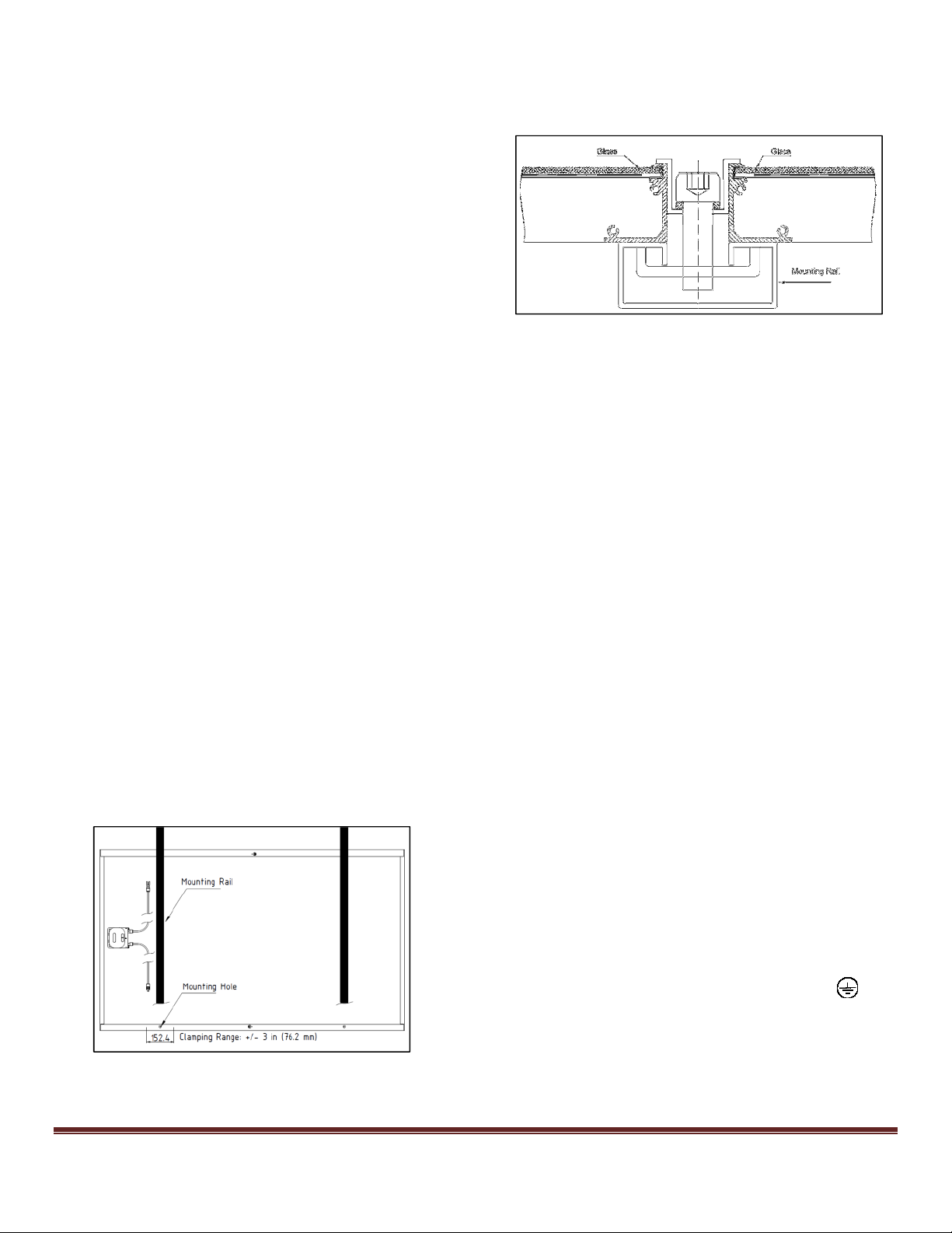
Rail Mounting
A supporting structure can be used to mount the modules at
various tilt angles. See Figure 1 for recommend
configuration. Ensure no dissimilar combinations of metals
be used that when damp or wet could result in degradation
of the materials and as a result create conditions that
prevent the module from meeting installation requirements
and instructions set forth in this manual.
The frame of each module has four mounting holes. These
are to be used to secure the module(s) to the supporting
structure. Use ¼ in. (or M6) bolt with a ¼ in. (or M6) flat
washer beneath bolt head and a ¼ in. (or M6) lock washers
between ¼ in. (or M6) nut and rail with a minimum of 80 in-lb
(9 N-m) of torque to secure bolt. Use only stainless steel
mounting hardware.
It is recommended that the mounting rails must be aligned
with the frame mounting holes (Figure 1) and run
perpendicular to the length of the module.
2
.
Clamp Mounting
Clamps can be used to achieve mounting to a support
structure. A minimum of four points of contact at the location
(+/- 3 in. or 76.2 mm) of pre-drilled mounting holes should be
used. See Figure 2 for typical clamp assembly.
Figure 2: Clamp Mounting Example Diagram
Equipment Grounding
A module with exposed conductive parts is considered to be
in compliance with UL 1703 only when it is electrically
grounded in accordance with the instructions presented
below and the requirements of the National Electrical Code
(NEC)
Where common grounding hardware (nuts, bolts, star
washers, spilt-ring lock washers, flat washers and the like) is
used to attach a listed grounding/bonding device, the
attachment must be made in conformance with the
grounding device manufacturer’s instructions.
Common hardware items such as nuts, bolts, star washers,
lock washers and the like have not been evaluated for
electrical conductivity or for use as grounding devices and
should be used only for maintaining mechanical connections
and holding electrical grounding devices in the proper
position for electrical conductivity. Such devices, where
supplied with the module and evaluated through the
requirements in UL 1703, may be used for grounding
connections in accordance with the instructions provided
with the module.
Ground the module in accordance with local requirements
and NEC Article 250 where applicable. Size and earth
ground conductor accordingly.
Earth conductors should be large enough for let-through
energy.
Methods to secure earth wires to PV module frame should
be mechanically sound to ensure electrical continuity at all
times.
When using a self-tapping screw to make bonding
connection ensure at least two full threads engage in the
metal.
Do NOT use bare copper grounding lug.
The following methods are certified for grounding the module.
For Canada; Grounding method must comply with Safety
Standard for Electrical Installations, Canadian Electrical
Code, Part 1. CSA C22.1
When using provided grounding holes on module frame
locate 4.2 +/- 0.2 mm diameter grounding holes shown in
Figure 3 that are marked by the grounding symbol. . The
flange on which the grounding hole is located
Figure 1: Mounting Hole Location and Example of Rail Mount
OPTXXX-##-4-1YY IEC & UL EN Suniva, Inc. SI&IM _9 Rev 9 Page 2
 Loading...