

Page 1
Embedded Electronics
Digital Proportional Valve Amplifier
The Embedded Electronics Amplifier is a compact, low profile coil/controller combination for use with proportional solenoid valves. The
Amplifier provides current to the coil in proportion to an input signal. Bright LED indicators on the unit provide an overview of the
operating status. Setup is accomplished using Sun’s PC-based Amplifier Set Up Software or Hand Held Programmer (HHP). There is
no cover to remove and no tiny pots to set. Once configured, the settings are stored in permanent memory within the unit.
Easily configured using Sun’s hand held interface or PC-based software
LED indication of Status and Output Current
Standard DIN 43650-Form A Connector
Selectable dither frequency up to 300 Hz
Adjustable current limi ted output wit h short circ uit protection
5 Volt reference for potentiometer/joystick controls is optional
Multiple modes for analog or 2-speed control
Programmable enable input optional
All input and output limits are independently adjustable
Adjustable ramp up and ramp down times, independently set
Microprocessor controlled for consistent, reliable performance
CE approved – see website product page for complete details
Operating Specifications:
Supply Voltage
Supply Current I
Output Current
Reference Voltage
790-2*24V: 21.6-28 V, 24V Recommended
790-2*12V: 10.8-28 V, 12V Recommended
+ 20 mA
SOL
790-2*24V: 24 V Coil, 600 mA max.
790-2*12V: 12 V Coil, 1200 mA max.
+5V @ 1 mA * Optional
790-2*24V
790-2*12V
Dither Settings 80-300 Hz, 20 Hz increments
Analog Input Range 0 – 10 V (source type)
Analog Input Impedance
Operating Temperature Range
13 K
-4 F to 158 F (-20 C to 70 C)
Enclosure Glass filled nylon with Lexan light pipes, polyurethane potting compound
Ramp Up Time 0 – 120.0 s, 0.5 s increments
Ramp Down Time 0 – 120.0 s, 0.5 s increments
Physical Descr iption
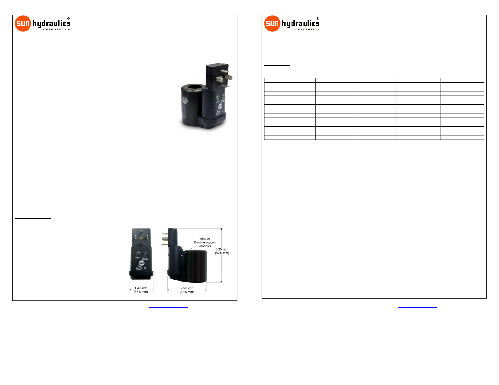
The Embedded Amplifier is shown at the right. There are two
indicator lamps labeled STATUS and ACTIVE. The STATUS lamp
will light green whenever power is applied to the unit and is within
the specified voltage range. The STATUS light will flash red when
a fault has occurred. The type of fault is indicated by the number
of successive flashes. It will continue to flash until the command
signal has been removed to clear the fault. The amber lamp
labeled ACTIVE provides an indication of the current being
supplied to the solenoid outputs.
Communication with the Embedded Amplifier takes place through
two infrared communication windows. These windows allow for
configuration and monitoring of the operating parameters, and
therefore must remain free from any obstruction such as paint or
other material. The infrared adapter cable clips onto the
Embedded Amplifier in the notches located between the coil
housing and amplifier section.
2012 Sun Hydraulics Corp. 23MAR12 # 999-991-234 www.sunhydraulics.com Page 1 of 8
Embedded Electronics
Digital Proportional Valve Amplifier
User Interface
The Embedded Amplifier has a number of internal settings which allow each unit to be configured for the application in
which it is used. These settings are accomplished using Sun’s PC-based Amplifier Set Up Software or Hand Held
Programmer (Sun p/n 991-700). Infrared Cables are available to communicate between the Amplier and the PC or the
HHP (USB cable p/n: 991-704 and Serial cable p/n: 991-702).
Parameter List
The following table outlines the parameter list for the Amplifier. Along with the name of the parameter and its type, the table lists the
limits and units for each item.
Parameter Type Limits Default Settings Units
790-2***V FIXED Version #
MODE VARIABLE See Mode Description 1 Mode #
MINIMUM INPUT VARIABLE 0 to 10.0 0.2 V
MAXIMUM INPUT VARIABLE 0 to 10.0 10 V
MINIMUM OUTPUT VARIABLE 0 to 600 or 1200 5 mA
MAXIMUM OUTPUT VARIABLE 0 to 600 or 1200 590 or 1150 mA
DITHER FREQ. VARIABLE Off, 80 to 300 140 Hz.
RAMP UP TIME VARIABLE 0.0 to 120.0 0 Seconds
RAMP DOWN TIME VARIABLE 0.0 to 120.0 0 Seconds
COMMAND SIGNAL MONITO R Volts
OUTPUT CURRENT MONITOR mA
SUPPLY VOLTAGE MONITOR Volts
FAULT STATUS MONITO R Fault
790-2***V – This is the title parameter. The model number of the unit and the firmware version are displayed. The title parameter is
fixed.
MODE – There are six modes of operation for the Amplifier. These modes are as follows:
1) Output proportional to input with Enable not used.
2) Output inversely proportional to input with Enable not used.
3) Output proportional to input with Enable. *
4) Output inversely proportional to input with Enable. *
5) Two speed where Enable provides output at the level set in Minimum Output and Command provides output at the level
set in Maximum Output. *
6) Two speed where Enable provides output at the level set in Maximum Output and Command provides output at the level
set in Minimum Output. *
* Note: Available modes are dependent upon the fourth pin option selected.
The Ramp Up and Ramp Down times apply to all modes. The Mode parameter is variable.
MINIMUM INPUT - The Minimum Input parameter is used to establish the minimum analog command which results in activation of the
output. The value shown in square brackets is the actual analog value except while in Inverse Modes 2 and 4. In the Inverse Mode, the
value shown in the square brackets is the inverse of the actual value, e.g. 10 V command is displayed as 0 V. The Minimum Input
parameter is a combination variable/monitor type.
MAXIMUM INPUT - The Maximum Input parameter is used to establish the maximum analog command for scaling of the output. The
output will hold its maximum value for any input equal to or greater than this value. The value shown in square brackets is the actual
analog value except while in Inverse Modes 2 and 4. In the Inverse Mode, the value shown in the square brackets is the inverse of the
actual value, e.g. 10 V command is displayed as 0 V. The Maximum Input parameter is a combination variable/monitor type.
MINIMUM OUTPUT - The Minimum Output parameter represents the minimum current of the output. This is often referred to as the
dead band. The value displayed represents the current in milliamps. The Minimum Output parameter is variable.
MAXIMUM OUTPUT - The Maximum Output parameter represents the maximum current of the output. This is often referred to as the
gain. The value displayed represents the current in milliamps. The Maximum Output parameter is variable.
DITHER FREQ. - The Dither Frequency parameter has 13 options for dither control. The choices are Off, 80 to 300 Hz in 20 Hz
increments. Dither control provides low frequency modulation which is required in many proportional valve applications. The Dither
Frequency parameter is variable.
RAMP UP/DOWN TIME - Ramp Up Time and Ramp Down Time are used to limit the rate of change of the input command signal, and
therefore the ramp time of the output. The amount of time required to ramp through the full input range is set by these parameters.
When the input command is increasing, the Ramp Up Time is used. When the input command is decreasing, the Ramp Down Time is
used. The Ramp Up/Ramp Down Time parameters are variable.
790-2*24V
790-2*12V
2012 Sun Hydraulics Corp. 23MAR12 # 999-991-234 www.sunhydraulics.com Page 2 of 8
Page 2
Embedded Electronics
Digital Proportional Valve Amplifier
COMMAND SIGNAL - The Command Signal displays the actual command signal to the device in Volts. The Command Signal
parameter is a monitor type. When working in one of the Inverse Modes, 2 and 4, the inverse of the command signal is displayed, e.g.
10 V command is displayed as 0 V.
OUTPUT CURRENT - Output Current displays the nominal current being supplied to the output. The Output Current parameter is a
monitor type.
SUPPLY VOLTAGE - The Supply Voltage parameter displays the module’s power supply voltage. This value is included as an aid to
troubleshooting. The Supply Voltage parameter is a monitor type.
FAULT STATUS - The Fault Status parameter displays the current fault code when a fault exists as shown in the table below. The
Fault Status parameter is a monitor type. In addition to the on-screen fault status, the STATUS light will flash red indicating a problem.
The light will flash a number of times periodically corresponding to the fault codes below.
Code Fault RED LED Flashes
1 Over Current
2 Open Output
3 Output Shorted
Configuration
All of the amplifier set up operations are accomplished with the use of 4 buttons. These buttons are Lock, Unlock, Up, and Down. The
Programmer represents these in graphical form as padlocks and arrows.
Both the PC-based set up software and the Hand Held Programmer have a two-line display. The up and down arrows are used to
navigate through the parameter list. When either button is pressed, the display will be updated with the next parameter in the list. The
parameter name will appear on the first line and the associated setting will appear on the second line. The list is accessed in a circular
fashion, stepping down from the last parameter to the first and vise-versa.
To change the setting of a variable parameter, the user must press the unlock button to place the system in edit mode. While in edit
mode, the display will show the Up and Down arrows together at the beginning of the second line. In edit mode, the up and down
buttons are used to change the value of the parameter. For parameters which contain both variable and monitor data, the monitor data
is shown surrounded by square brackets. Once the desired setting is displayed, pressing the lock button will save the parameter and
end the edit mode.
Ordering Information
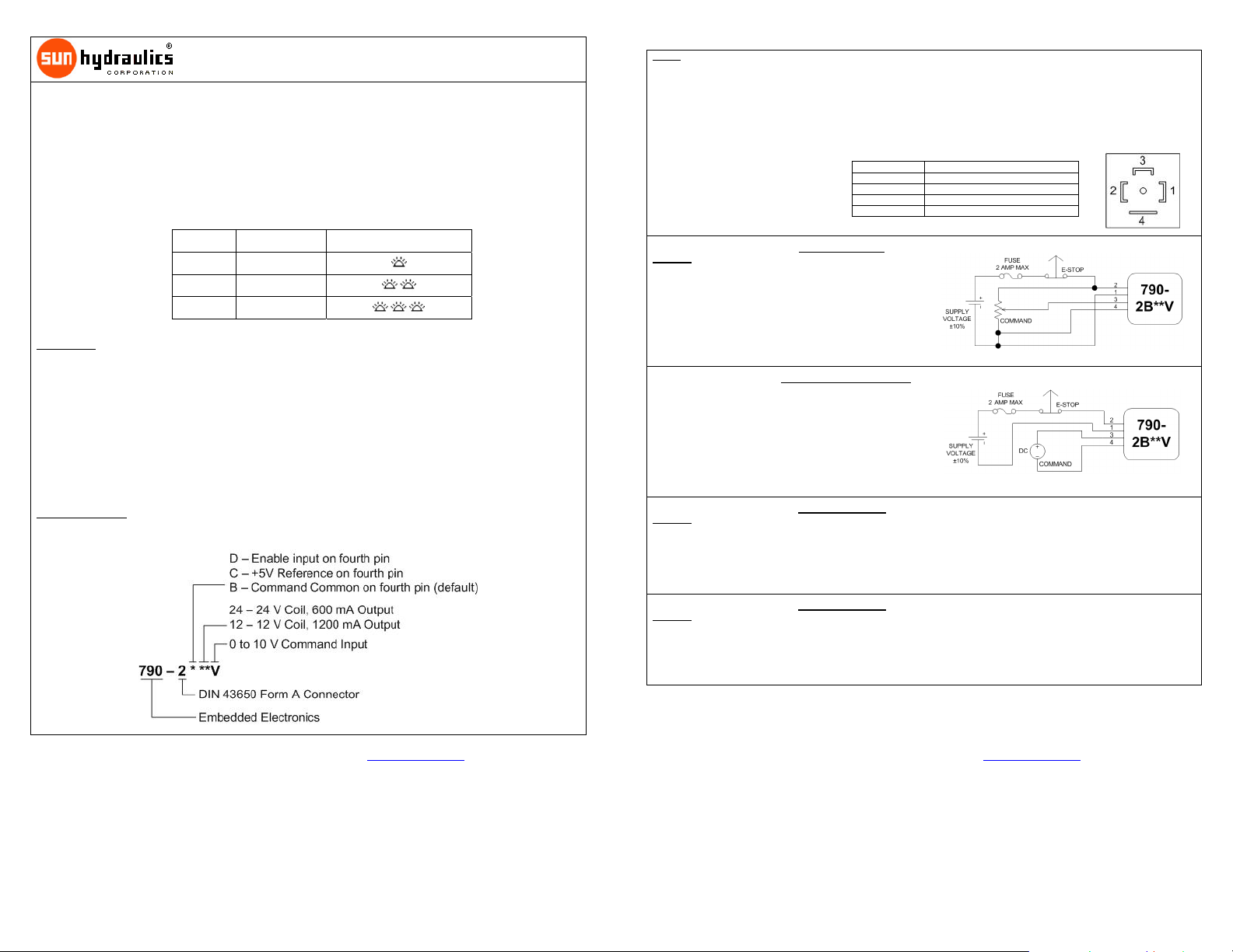
The following is a breakdown of the 790-2***V part numbering system:
790-2*24V
790-2*12V
Wiring
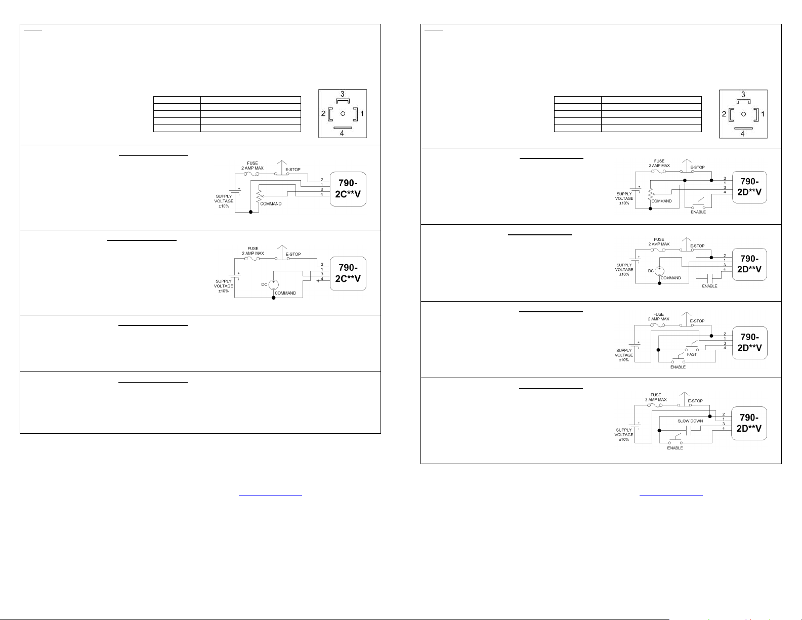
Wiring functions are listed in the table below. Following the table are wiring examples for various modes of operation.
Notes:
To establish the infrared communications link, it is essential that the infrared communication windows remain free from any
obstruction such as paint or other mate rial.
For acceptable EMC immunity, a shielded cable should be used. Shield drain should be attached to earth ground.
For complete overload protection, a fuse should be installed as shown in the circuit diagrams.
Note: A source type input is
required. A sinking type analog input
will damage the amplifier.
Single Solenoid Joystick Control, Option B-Command
Common
The Amplifier can be controlled with a joystick or potentiometer as
shown. This configuration uses Mode 3 with the Enable signal or
Mode 1 with no Enable line.
Single Solenoid PLC Control, Option B- Command Common
The Amplifier can be controlled with PLC as shown. This
configuration uses Mode 3 with the Enable signal or Mode 1 with
no Enable line.
Single Solenoid 2-Speed Control, Option B- Command
Common
The Amplifier can be configured for 2-speed mode as shown. In
this arrangement the Enable signal allows minimum output and
the Command signal allows maximum output. This configuration
corresponds to Mode 5.
Terminal Function
1 Supply Common
2 +V Supply
3 Command Input
4 Option B- Command Common
N/A
2012 Sun Hydraulics Corp. 23MAR12 # 999-991-234 www.sunhydraulics.com Page 3 of 8
Single Solenoid 2-Speed Control, Option B- Command
Common
The Amplifier can be configured for 2-speed mode as shown. In
this arrangement the Enable signal allows maximum output and
the Command signal limits output to the minimum setting. This
configuration corresponds to Mode 6.
2012 Sun Hydraulics Corp. 23MAR12 # 999-991-234 www.sunhydraulics.com Page 4 of 8
N/A
Page 3
Wiring
Wiring functions are listed in the table below. Following the table are wiring examples for various modes of operation.
Notes:
To establish the infrared communications link, it is essential that the infrared communication windows remain free from any
obstruction such as paint or other mate rial.
For acceptable EMC immunity, a shielded cable should be used. Shield drain should be attached to earth ground.
For complete overload protection, a fuse should be installed as shown in the circuit diagrams.
Note: A source type input is
required. A sinking type analog input
will damage the amplifier.
Terminal Function
1 Supply Common
2 +V Supply
3 Command Input
4 Option C- +5V Reference
Wiring
Wiring functions are listed in the table below. Following the table are wiring examples for various modes of operation.
Notes:
To establish the infrared communications link, it is essential that the infrared communication windows remain free from any
obstruction such as paint or other mate rial.
For acceptable EMC immunity, a shielded cable should be used. Shield drain should be attached to earth ground.
For complete overload protection, a fuse should be installed as shown in the circuit diagrams.
Terminal Function
Note: A source type input is
required. A sinking type analog input
will damage the amplifier.
1 Supply Common
2 +V Supply
3 Command Input
4 Option D- Enable Input
Single Solenoid Joystick Control, Option C- +5V Reference
The Amplifier can be controlled with a joystick or potentiometer as
shown. This configuration uses Mode 3 with the Enable signal or
Mode 1 with no Enable line.
Single Solenoid PLC Control, Option C- +5V Reference
The Amplifier can be controlled with PLC as shown. This
configuration uses Mode 3 with the Enable signal or Mode 1 with
no Enable line.
Single Solenoid 2-Speed Control, Option C- +5V Reference
The Amplifier can be configured for 2-speed mode as shown. In
this arrangement the Enable signal allows minimum output and
the Command signal allows maximum output. This configuration
corresponds to Mode 5.
Single Solenoid 2-Speed Control, Option C- +5V Reference
The Amplifier can be configured for 2-speed mode as shown. In
this arrangement the Enable signal allows maximum output and
the Command signal limits output to the minimum setting. This
configuration corresponds to Mode 6.
N/A
N/A
Single Solenoid Joystick Control, Option D- Enable Input
The Amplifier can be controlled with a joystick or potentiometer as
shown. This configuration uses Mode 3 with the Enable signal or
Mode 1 with no Enable line.
Single Solenoid PLC Control, Option D- Enable Input
The Amplifier can be controlled with PLC as shown. This
configuration uses Mode 3 with the Enable signal or Mode 1 with
no Enable line.
Single Solenoid 2-Speed Control, Option D- Enable Input
The Amplifier can be configured for 2-speed mode as shown. In
this arrangement the Enable signal allows minimum output and
the Command signal allows maximum output. This configuration
corresponds to Mode 5.
Single Solenoid 2-Speed Control, Option D- Enable Input
The Amplifier can be configured for 2-speed mode as shown. In
this arrangement the Enable signal allows maximum output and
the Command signal limits output to the minimum setting. This
configuration corresponds to Mode 6.
2012 Sun Hydraulics Corp. 23MAR12 # 999-991-234 www.sunhydraulics.com Page 5 of 8
2012 Sun Hydraulics Corp. 23MAR12 # 999-991-234 www.sunhydraulics.com
Page 6 of 8
Page 4
Embedded Electronics
Digital Proportional Valve Amplifier
Setup Procedure
Note: Changing parameter settings may cause sudden and unexpected
machine movements. Care must be taken to prevent injury, death, or
damage of equipment.
1. Install the infrared Cable Adapter to the Embedded Amplifier paying
particular attention to the orientation of the Adapter—the logo side should
face away from the coil and towards the embedded amplifier. The connector
end must connect to either a PC (with set up software loaded) or the HHP.
2. Power must be applied to the Embedded Amplifier. When using the HHP,
turn on the HHP by briefly pressing the yellow power button marked with the
international power symbol l|0. The title screen for the HHP should appear.
When using the PC-based set up software, load the program.
3. Parameter definition should be set in the descending order as shown in the
parameter table above to avoid a common mistake.
4. Pressing the green Unlock button when a variable parameter is displayed
puts the amplifier into the edit mode.
5. With the MODE parameter displayed on the LCD screen, the correct mode
setting is selected by pressing the green Unlock button to enter the edit
mode. Use the Up or Down arrows to scroll through the list of six modes. Not all modes of operation will be available and will
depend on the fourth pin option selected. The mode is determined by the intended use and the typical wiring diagrams shown
on the previous page. Once the correct mode has been selected, press the red Lock button to commit the change to memory
and exit the edit mode.
6. Press the Down arrow to display the MINIMUM INPUT parameter. The first number shown on the second line is the setting
value that is a variable. The second number, shown in square brackets, is the monitored value currently present. Pressing
the Unlock button enters the edit mode. The minimum input setting can be changed by pressing the Up arrow to increase the
value or the Down arrow to decrease the setting. The value selected is determined by the minimum command value that is
achievable recognizing that selecting a value lower that is actually achievable will not allow for the optimum linearity and
selecting a value too high reduces the control resolution. Selecting a value too low could also make the amplifier susceptible
to electro-magnetic interference (EMI). The smallest value that may be selected is 0 Volts. Once the value has been selected,
pressing the red Lock button commits the change to memory and exits the edit mode. When working in the Inverse Mode, the
monitored value displayed is the inverse value, e.g. 10 V command is displayed as 0 V.
7. Press the Down arrow to display the MAXIMUM INPUT parameter. Again the first number shown on the second line is the
setting value and it is variable. The second number, shown in square brackets, is the monitored value currently present.
Pressing the Unlock button allows the value to be edited either by increasing as the Up arrow is pressed or decreased as the
Down arrow is pressed. The value selected is determined by the maximum command value that is achievable recognizing
that selecting a value that is too high will not allow for the optimum linearity and selecting a value that is too low reduces the
control resolution. The maximum value that may be selected is 10 Volts. Once the value has been selected, pressing the red
Lock button commits the change to memory and exits the edit mode. When working in the Inverse Mode, the monitored value
displayed is the inverse value, e.g. 10 V command is displayed as 0 V.
8. Press the Down arrow to display the MINIMUM OUTPUT parameter. This parameter is sometimes called dead band
compensation. The first number shown on the second line of the display is the setting value while the number in square
brackets is the monitored value currently present. Pressing the green Unlock button enters the edit mode to allow for the
setting to be changed. Press the Up arrow to increase the value or press the Down arrow to decrease the value. The value
specified is determined by what value of current is needed when the MINIMUM INPUT value has been reached. A low value
will increase the control resolution while a higher value will compensate for the difference for the current value between the
valve components not moving and moving. Once the value has been selected, pressing the red Lock button commits the
change to memory and exits the edit mode.
9. Press the Down arrow to display the MAXIMUM OUTPUT parameter. Again the first number shown on the second line is the
setting value while the number in square brackets is the monitored value currently present. Pressing the green Unlock button
enters the edit mode to allow for the setting to be changed. Press the Up arrow to increase the value or press the Down arrow
to decrease the value. The value selected is determined by the pressure or flow required at maximum power to the solenoid
coil. However, the maximum current value should not exceed the recommended value for the coil being used. Exceeding the
recommended value will dramatically shorten the life of the coil by producing excess heat. Presently, the recommended
maximum current value for a Sun coil produced after January 2005 (black dichromate coil can) is 590 mA for a 24 Volt coil and
1150 mA for a 12 Volt coil. Selecting a value too low will limit the performance of the valve. Once the value has been
selected, pressing the red Lock button commits the change to memory and exits the edit mode.
790-2*24V
790-2*12V
10. Press the Down arrow to display the DITHER FREQ. parameter. The number shown on the second line is the dither
frequency in Hertz. Presently, the recommended dither frequency for Sun valves is 140 Hz. Dither is a small amplitude
oscillation at the specified frequency used to reduce friction within the valve that allows for better performance. The lower the
frequency, the larger the amplitude of oscillation and vice versa, the larger the frequency, the smaller the amplitude of
oscillation. The amplitude is not user definable and cannot be set independently. Once the value has been selected, pressing
the red Lock button commits the change to memory and exits the edit mode.
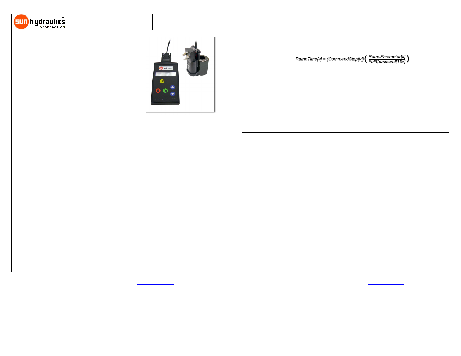
11. The RAMP UP and RAMP DOWN parameters are ramp rates determined by the rate input as described in steps 12 and 13
below. The equation below describes the relationship between actual ramp time in seconds and the RAMP UP/DOWN
parameter in seconds.
12. Press the Down arrow to display the RAMP UP parameter. The number shown on the second line is the ramp time in
seconds. A value between 0 and 120 seconds may be selected. Once an increase in command is detected, the Amplifier will
increase power to the coil in a linear manner over the ramp rate selected. Once the value has been selected, pressing the red
Lock button commits the change to memory and exits the edit mode.
13. Press the Down arrow to display the RAMP DOWN parameter. The number shown on the second line is the ramp time in
seconds. A value between 0 and 120 seconds may be selected. Once a decrease in command is detected, the Amplifier will
decrease power to the coil in a linear manner over the ramp rate selected. The RAMP UP and RAMP DOWN parameters are
not required to be the same. Once the value has been selected, pressing the red Lock button commits the change to memory
and exits the edit mode.
14. Setup of the Embedded Amplifier is complete. Continuing to press the Down arrow allows viewing of the monitored
parameters supply voltage, output current, and fault status. The monitored parameters are useful in troubleshooting.
2012 Sun Hydraulics Corp. 23MAR12 # 999-991-234 www.sunhydraulics.com Page 7 of 8
2012 Sun Hydraulics Corp. 23MAR12 # 999-991-234 www.sunhydraulics.com Page 8 of 8
 Loading...