

Sunheat SH1500RC BB Repair Manual

SH1500RC BB
Repair Guide
The Unit Does Not Turn On
1. Make sure that the power cord is plugged into an
energized outlet.
2. Make sure you have turned the power on by pressing
the on/off button on the front display screen. The
screen will light up if the screen is on.
3. Make sure there are no timers set on the front display
screen.
A. How To Remove The Center Unit From Wooden Cabinet
B. How To Replace The Front Display Screen
C. How To Replace The Power Cord
D. How To Replace The High Limit Switch
E. How To Replace The Temperature Sensor
F. How To Replace The Fan Switch (45c)
G. How To Replace Reset Button
H. How To Replace The Quartz Infrared Heat Tubes
I. How To Replace The 12volt Fan
J. How To Replace The Circuit Board
K. How To Replace The Power Routing Board (PRB)
L. Wiring Diagram
PLEASE CALL CUSTOMER SERVICE
FOR ASSISTANCE:
1-877-467-8643
A
How To Remove The Center From The Wooden
Cabinet
!!Unplug The Heater Before Servicing!!
(Remember That the Edges of the Metal Are Sharp. Use Caution)
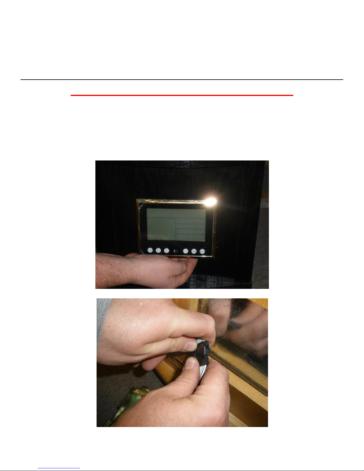
Remove the front display screen by pushing up and pulling out on the bottom. Unplug the
black quick connect.
NOTE: When putting the display screen back, make sure you insert the top first then push the
bottom into place.
A
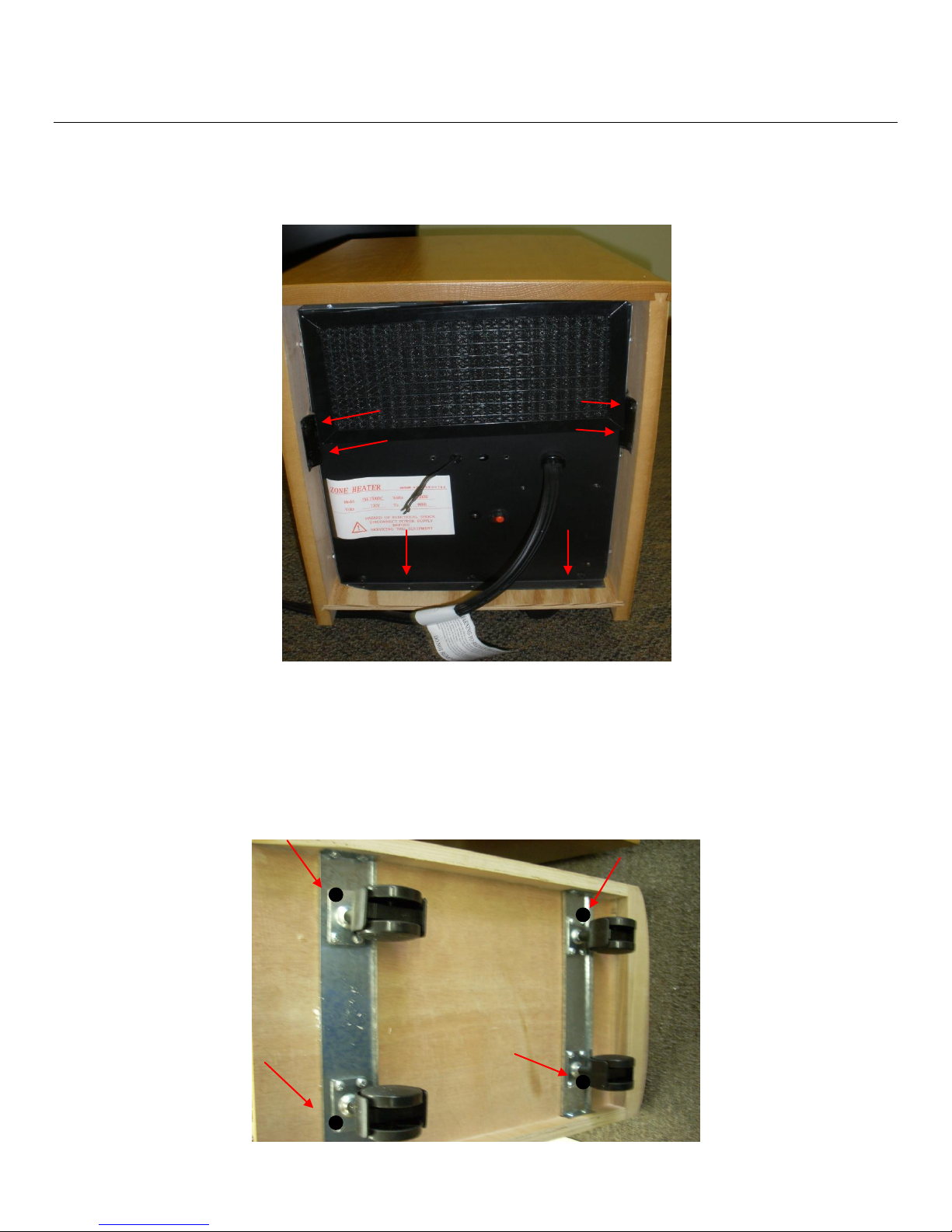
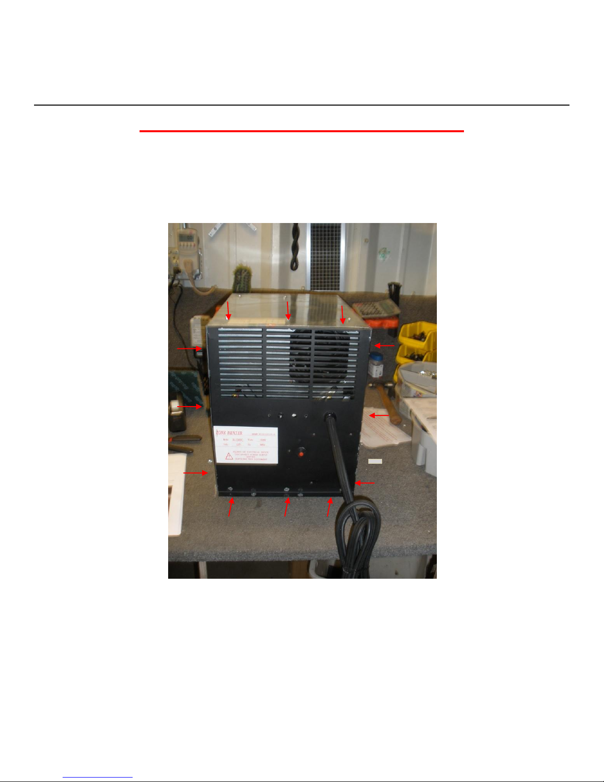
Remove the 6 screws on the back of the heater. (SEE PHOTO BELOW FOR SCREW
LOCATIONS).
Turn the heater on its side and remove the outer corner screws on each caster mounting bracket.
These screws will be about 1½ inches long (SEE PHOTO BELOW FOR SCREW
LOCATIONS). After removing all of the anchor screws, the center unit will slide out easily.
**You may use the power cord to gently pull the metal center unit out of the wooden cabinet.
B
How To Replace The Front Display Screen
!!Unplug The Heater Before Servicing!!
(Remember That the Edges of the Metal Are Sharp. Use Caution)
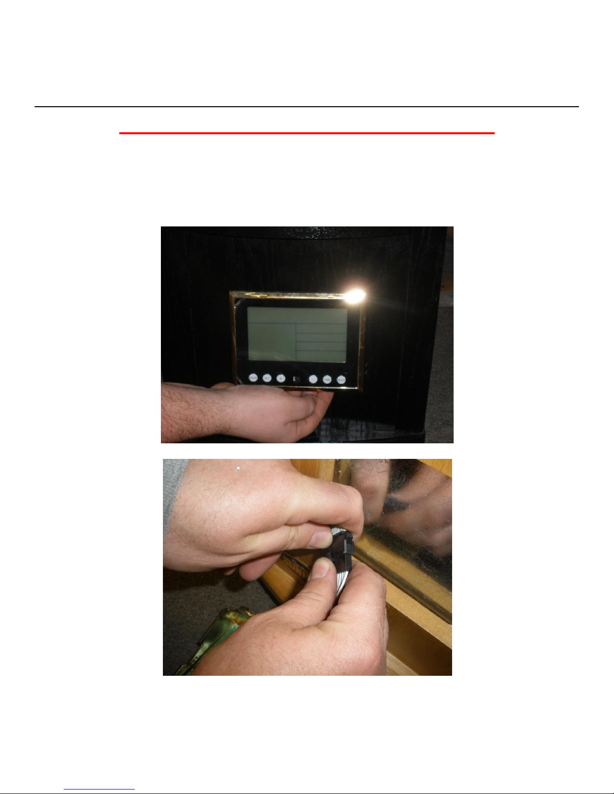
Remove the front display screen by pushing up and pulling out on the bottom. Unplug the
black quick connect. NOTE: When putting the display screen back, make sure you insert the
top first then push the bottom into place.

C
Quick Connect
How To Replace The Power Cord
!!Unplug Heater Before Servicing!!
(Remember That the Edges of the Metal Are Sharp. Use Caution)
Remove all of the screws that hold the right & the left side panels on to the heater. Remove the
6 remaining screws that hold the rear panel in place. There are 3 located on the top panel and 3
on the bottom portion of the back panel (SEE PHOTO BELOW FOR SCREW LOCATION
& PANEL IDENTIFICATION).
Remove the power cord retaining grommet using a pair of pliers. Squeeze the cord strain relief
and pull out it from the back.
NOTE: IT IS RECOMMENDED THAT YOU REMOVE THE QUICK CONNECTS FROM
THE HEATER AND DIRECT WIRE TO THE POWER ROUTING BOARD. PLEASE
REFER TO INSTRUCTIONS ON HOW TO ELIMINATE THE QUICK CONNECTS IF YOU
HAVE THEM.
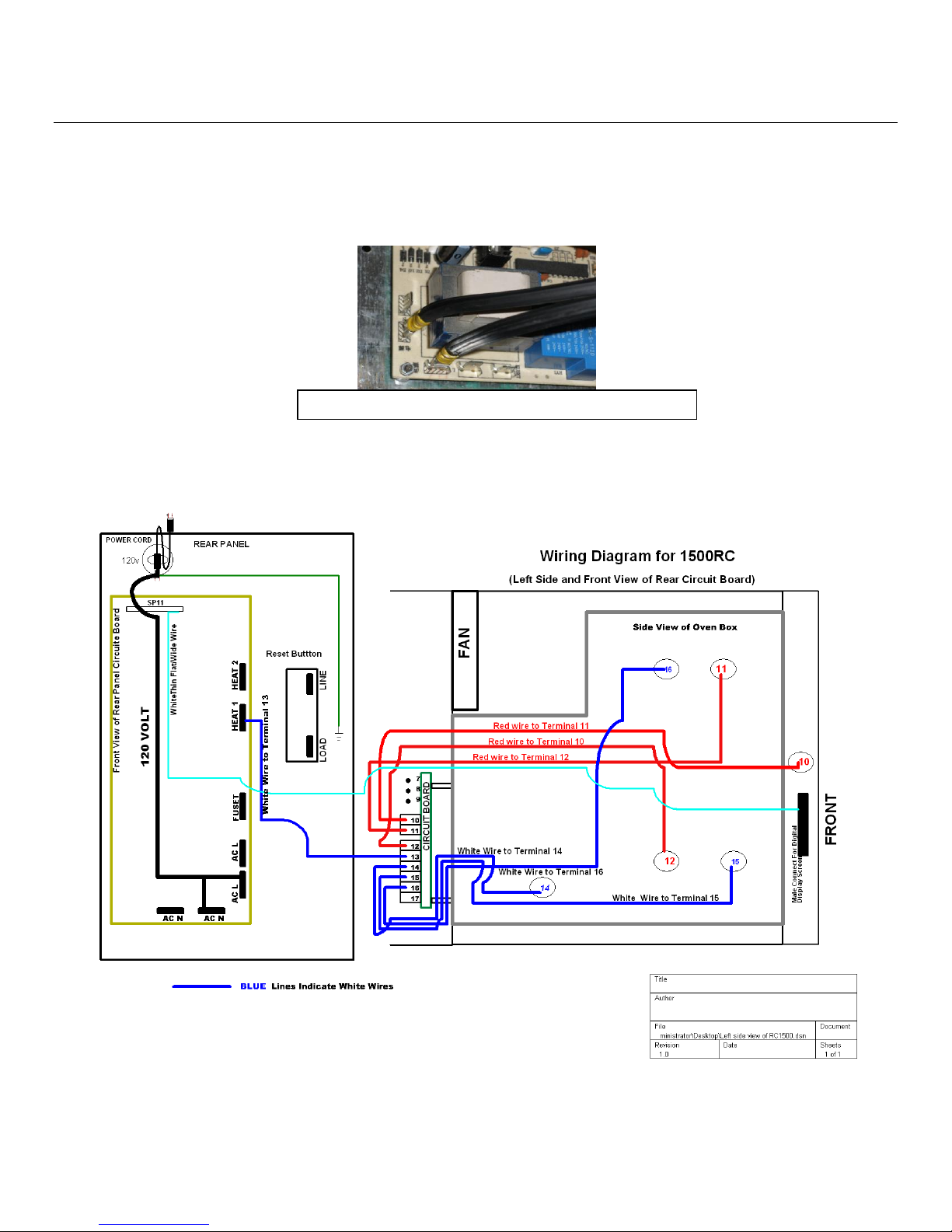
C
Close up of circuit board and 2 power cord wires attached
Disconnect the green ground wire. Install the new power cord and directly attach the two wires
to the circuit board. Reattach the green ground wire.
NOTE: The two black wires to power cord are universal so it doesn’t matter which goes to
which location.
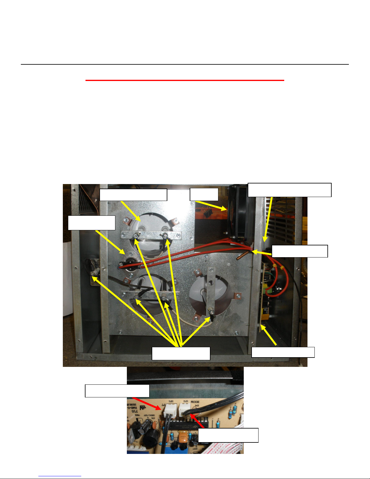
D
Heating elements
High Limit Switch
Copper Heat Exchanger
Fan Switch
Fan
Power Routing Board
Circuit Board (not pictured)
High Limit Switch
Temperature Sensor
How To Replace The High Limit Switch
!!Unplug Heater Before Servicing!!
(Remember That the Edges of the Metal Are Sharp. Use Caution)
Lay the metal unit on its right side (when you are looking at the back of the unit). Remove the
screws on the left side and lift the panel off. You should now see the 3 round copper heat
exchangers, 5 short quartz infrared heat tubes suspended inside of the copper exchangers, 1 long
heating element, and the circulation fan (Fan will be to your right). The High Limit Switch is a
thin black wire with a metal end. To replace the High Limit Switch you will need to unplug it
from the “SP2 PT” terminal on the circuit board. Remove the faulty switch and replace. Make
sure it is plugged back into the correct location (SEE PHOTO BELOW FOR HIGH LIMIT
SWITCH LOCATION).
E
How To Replace The Temperature Sensor
!!Unplug Heater Before Servicing!!
(Remember That The Edges Of The Metal Are Sharp. Use Caution)
Remove 3 screws from each panel to remove the back panel. There are 3 screws on the top,
bottom, and each side panel. There will be 12 screws total (SEE PHOTO BELOW FOR
SCREW LOCATION & PANEL IDENTIFICATION).
 Loading...