

Page 1
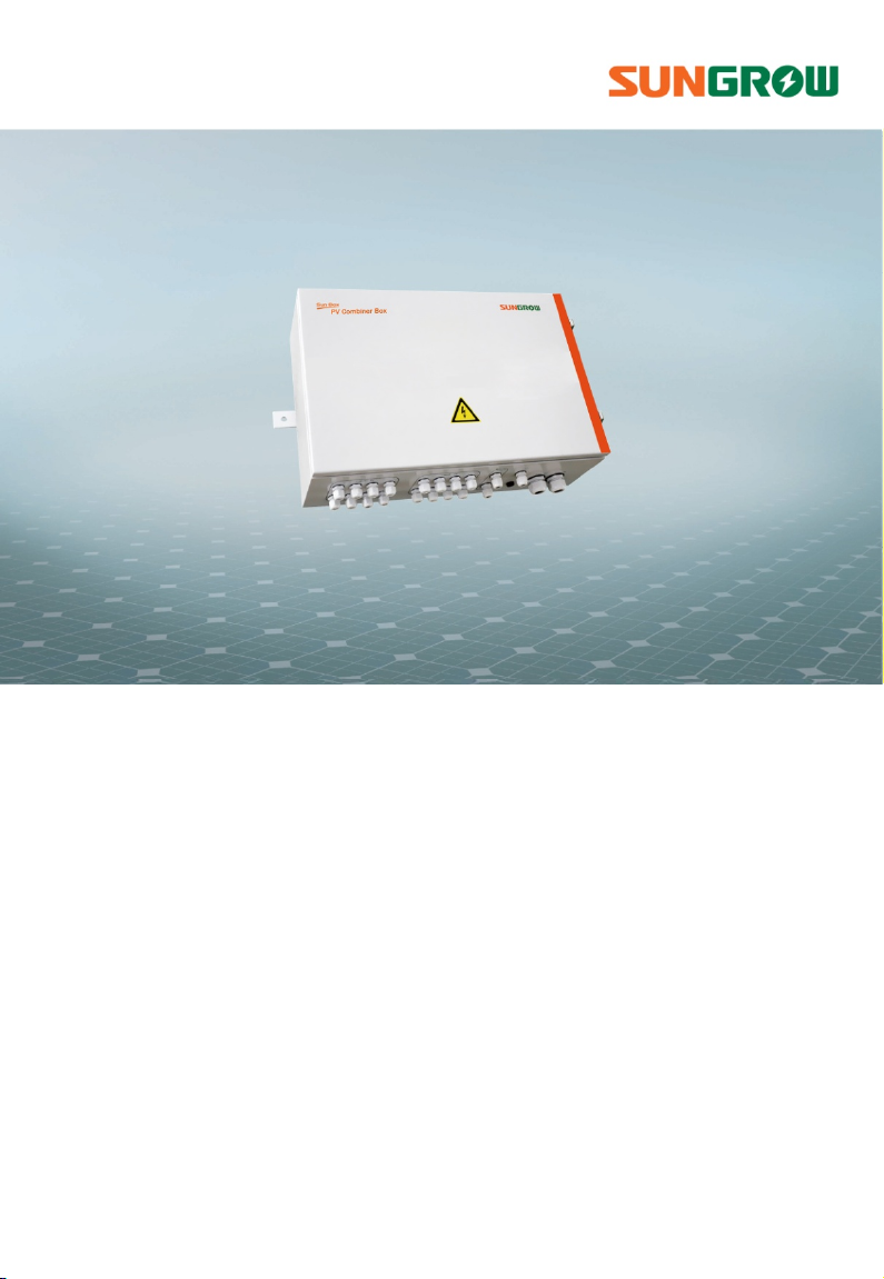
SunBox PVS-8M/PVS-16M
PV Array Combiner Box
User Manual
Page 2

Page 3

Contents
1 About This Manual ................................................................... 1
1.1 Contents .................................................................................................................... 1
1.2 Target Readers ........................................................................................................ 1
1.3 How to Use this Manual ....................................................................................... 1
1.4 Other Information ................................................................................................. 2
1.5 Symbol Explanation .............................................................................................. 2
1.6 Picture Explanation ............................................................................................... 3
2 Safety Instructions ................................................................... 4
3 Product Description ................................................................. 8
3.1 System introduction ............................................................................................. 8
3.2 Demonstration of the type ................................................................................. 9
3.3 Identifying the PVS ............................................................................................. 10
3.4 Fuse rating ............................................................................................................. 11
3.5 DC switch rating .................................................................................................. 11
4 Installation Guide .................................................................. 12
4.1 Checking before installation ........................................................................... 12
4.2 Mechanical installation ..................................................................................... 12
4.2.1 Dimensions ............................................................................................................... 12
4.2.2 Installation site requirements ............................................................................ 13
4.2.3 Preparation before Installation ......................................................................... 13
4.2.4 Installation Method ............................................................................................... 14
4.3 Electrical installation .......................................................................................... 16
4.3.1 Internal structure .................................................................................................... 16
4.3.2 Water-proof terminals and wirings .................................................................. 17
4.3.3 Wiring preparations ............................................................................................... 18
4.3.4 Input wiring and connections ........................................................................... 19
4.3.5 Output wiring and connections ....................................................................... 22
4.3.6 Ground wiring and connections ...................................................................... 24
Page 4

4.3.7 Communication Connections ........................................................................... 24
4.3.8 Installation of fuses ................................................................................................ 27
4.3.9 Bottom wirings ........................................................................................................ 27
4.4 Communication address settings ................................................................. 28
4.5 Start/Stop of operation .................................................................................... 31
5 Commissioning....................................................................... 32
6 Routine Maintenance ............................................................. 33
6.1 Replace the Fuse ................................................................................................. 33
6.2 Replace the sealing strip .................................................................................. 34
7 Troubleshooting ..................................................................... 35
7.1 Before troubleshooting .................................................................................... 35
7.2 Common faults and troubleshooting ......................................................... 35
8 Appendix ................................................................................ 38
8.1 Technical data ...................................................................................................... 38
8.2 Cable requirements ........................................................................................... 39
8.3 Quality Assurance ............................................................................................... 39
8.4 About us ................................................................................................................. 41
Page 5

1 About This Manual
1.1 Contents
Safety instructions
Safety instructions for the installation, operation, commissioning and
maintenance of PVS.
Product description
Location of PVS in the PV system, structure, function and classification.
Installation guide
The installation methods and electrical connections of PVS.
Routine maintenance
How to replace the fuses of PVS.
Others
Technical data of PVS, exclusion of liability and the way to contact us.
1.2 Target Readers
This manual is for users who operate the PVS or conduct the maintenance work. The
operators must be trained and qualified personnel.
1.3 How to Use this Manual
Read this manual and other related documents before installation of the PVS.
Documents must be stored in a convenient place for future reference.
The contents of the manual will be periodically updated or revised due to the
product development. It is probably that there are changes of manual in the
subsequent converter edition.
1
Page 6
1 About This Manual User Manual
1.4 Other Information
To satisfy your requirements, we have also provided PVS-6M and PVS-12M with a DC
input string number of 6 and 12 respectively. Their electrical structure, installation
and use are the same with those of SunBox PVS-8M/PVS-16M.
This manual takes SunBox PVS-8M/PVS-16M for example. For installation and
operation of combiner box with other inputs, please refer to this manual.
In actual application, if the PV string input numbers are not 8, 12, or 16,
user needs to set related parameters from the monitoring board of the
PVS to ensure its normal operation. For detailed setting methods, please
refer to “chapter 4.4”.
1.5 Symbol Explanation
This manual contains important safety and operational instructions that must be
accurately understood and followed during the installation and maintenance of the
equipment.
To ensure optimum use of this manual, note the following explanations of symbols
used.
DANGER indicates a hazard with a high level of risk which, if not avoided,
will result in death or serious injury.
WARNING indicates a hazard with a medium level of risk which, if not
avoided, will result in death or serious injury.
CAUTION indicates a hazard with a low level of risk which, if not avoided,
will result in minor or moderate injury.
2
Page 7
User Manual 1 About This Manual
NOTICE indicates a situation which, if not avoided, will result in equipment
malfunction or property damage.
NOTE indicates additional information, emphasized contents or tips to
help you solve problems or save time.
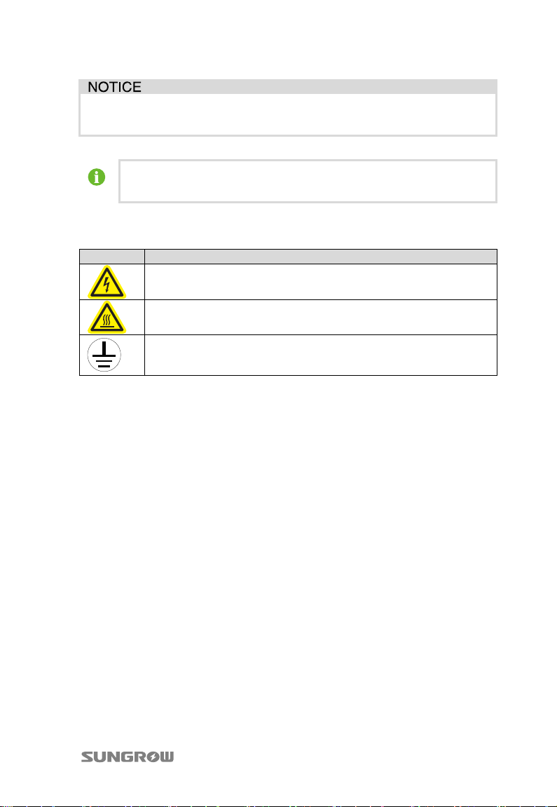
The following symbols on the device enclosure must be paid attention to.
Symbols Explanation
Risk of electric shock! If not avoided, lethal hazard can be caused.
Hot surface! Do not touch!
The symbol represents protective conductor terminal. The terminal
should be connected firmly to avoid potential injury or property
damage.
1.6 Picture Explanation
Pictures used in this manual all take the PVS with standard configuration for
example.
The real PVS you received may differ from the example pictures in the numbers of
the installation hangers and etc. please refer to the actual product you receive.
3
Page 8
2 Safety Instructions
This chapter describes some important safety instructions about SunBox PVS.
Please read the manual carefully before installation. If any device damage occurs
when ignoring the safety instructions, our company has the right to exclude all
warranty claims.
Lethal Voltage!
Death resulting from burning and electric shock upon touching the live
components of the PVS.
Disconnect the end connection of the PV string before cable connection;
Observe all safety instructions required by the PV cell manufacturer.
Device damage or system fault may cause fire and electric shock!
Optical check the device for any possible damages or dangerous states
before operation.
Check if other external devices or circuit connection are in safe state.
Work on the device only when it is safe to do so.
Death or burning hazard by touching the internal terminals of the device!
Do not touch the terminals or conductors in contact to the inverter or PV
string.
Observe all the instructions and safety regulations related to PVS
connection.
4
Page 9
User Manual 2 Safety Instructions
High voltage is present inside the device!
Follow all the warning signs in the device.
Respect all the safety instructions in this manual and other documents.
The ground cable must be grounded properly, otherwise,
lethal electric shock happens to the operator or installer once a fault
occurs.
device may be damaged after lightening stroke.
Incorrect cable connection may cause damages to the PV cells, combiner
box and inverter. Respect the following instructions during cable
connection:
Connect by strictly following the circuit diagram;
Measure and make sure the string open-circuit voltage meets the
requirements of the combiner box before inserting the fuse;
Identify the positive pole and negative pole before connection.
Only qualified personnel or professional electrician can perform the
operation and wiring described in this manual.
All operations and wirings must in full accordance with the national and
local standards and requirements.
All warning marks and labels must be clear and intact. Replace them if any
damages are found.
5
Page 10
2 Safety Instructions User Manual
Make sure the terminals are firmly connected during wiring. If the cable
copper core and the terminals are not connected firmly, terminals will be
over-heating and burnt. Anti-flaming cables with multi-strand are advisable
and the cable cross-sectional area should be no less than the recommended
value.
The nuts of the water-proof terminals must be firmly screwed to prevent
water leakage and PVS damages.
Pull the fuse out of the fuse holder for personal and device safety.
Watch out during fuse replacement. Do not touch the fuse with bare hands.
Do not bring any metallic materials during fuse replacement. Replace only
one fuse at one time. Once the one fuse is replaced, check to make sure the
new one is installed firmly and then replace the next one.
The fuse is under high voltage both from the inverter and the PV array. Do
not touch the fuse during device operation.
Disconnect the DC circuit breaker before checking or replacing the fuse.
Notice that all terminals of the DC circuit breaker contain high voltage.
Measure by using proper tools that the current of each input is zero before
replacing the fuse.
Lock the cabinet door and seal the water-proof cover of the lock core after
operation. In rooftop horizontal installation site, fix the auxiliary protection
set of the cabinet with bolts.
No not open the cabinet door frequently.
6
Page 11

User Manual 2 Safety Instructions
Touching or improper operation on the PCB or other sensitive components
may damage the device.
Do not touch any parts inside the cabinet other than the connection
terminals.
Respect all ESD related safety regulations and wear antistatic wrist strap.
7
Page 12
3 Product Description
3.1 System introduction
For a large-scale grid-connected PV system, it is widespread to install a DC
combining device between PV modules and inverters to minimize cable
connections, facilitate maintenance and enhance reliability.
Our SunBox PVS combiner box series (PVS) are designed for meeting these
requirements, which provides a turnkey solution for PV plant systems.
Considering different types of PVS, a certain number of PV strings can be connected
to the input side of PVS. After combining work done, at the output side, there will be
one DC+ and one DC- main line. By using of surge protection device (SPD) and
circuit breakers, the output can be connected to inverters directly.
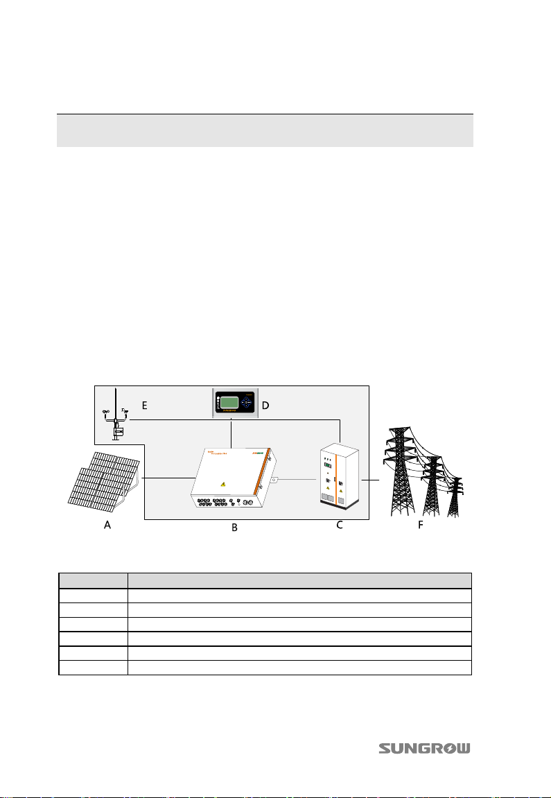
The PV generation system including a PVS is shown in Fig. 3-1.
Fig. 3-1 Composition of PV generation system
Tab. 3-1 Device in Fig. 3-1
No. Device
A PV arrays
B SunBox PVS-8M/PVS-16M combiner box
C Inverter
D Data acquisition device
E Environment monitoring device
F Grid
For PVS-8M, up to 8 PV strings can be connected to the input side.
And for PVS-16M, up to 16 PV strings can be connected to the input side.
8
Page 13
User Manual 3 Product Description
PVS has the following features:
Meet outdoor installation requirement
Connect to multiple PV inputs with fuse for each input (can be replaced to other
degree)
PV-specific high voltage SPD equipped, lightening protection function for
positive and negative pole
Quadrupole switch with positive and negative pole in parallel connection to
improve DC voltage-withstand value
Current sensor inside to monitor the current of each string; the monitored
information can be displayed by the LED or sent by RS485
Monitor busbar voltage and the monitored information can be displayed by the
LED and sent by RS485
3.2 Demonstration of the type
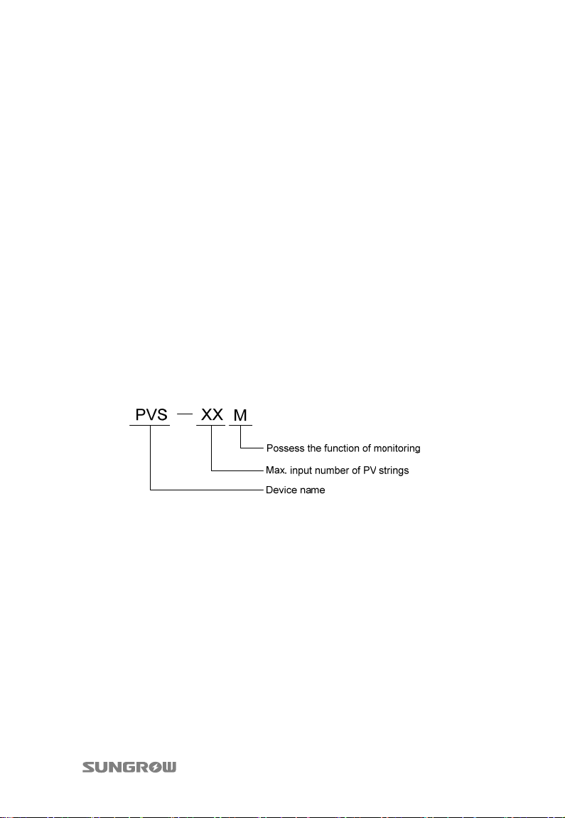
Type of the PVS is illustrated below:
9
Page 14
3 Product Description User Manual
3.3 Identifying the PVS
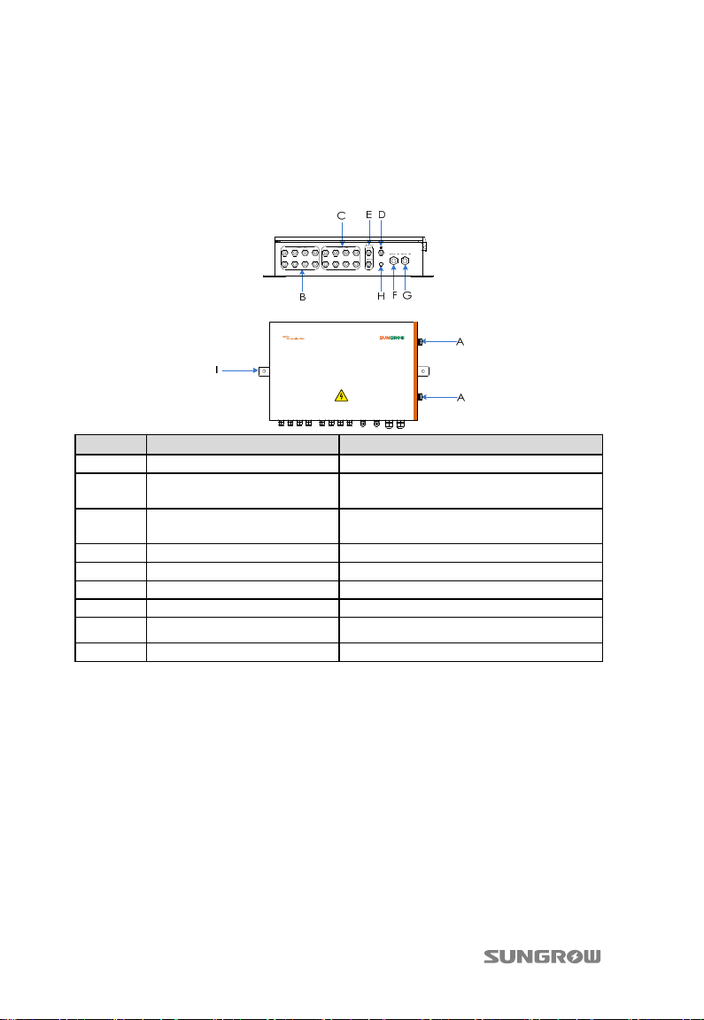
PVS-8M/PVS-16M is shown in the following picture
No. Name Description
A Lockhole -
B INPUT DC+
C INPUT DC-
D Ground terminal Equivalent potential connection terminal
E MONITOR Monitoring input and output
F OUTPUT DC+ Positive pole of DC output
G OUTPUT DC- Negative pole of DC output
H Ingress-protected air valve
I Fixing hanger Allow fixing of combiner
Positive pole of DC input
(unused terminals must be sealed)
Negative pole of DC input
(unused terminals must be sealed)
——
10
Page 15

User Manual 3 Product Description
3.4 Fuse rating
In power system, fuses are used for over-current protection. Choosing right-rating
fuses is very important to ensure safety operation.
The minimum current rating of a fuse can be calculated with short circuit current (Isc)
of PV arrays. Except for some special needs, the recommended rating would be
1.56×Isc.
Users can calculate fuse rating easily. If maximum current of PV arrays=7A, and DC
voltage range of PV arrays=200~1000V, then the fuse rating will be
1000V/(1.56×7A).
3.5 DC switch rating
The DC voltage of the switch is decided by the nameplate. For example, from the
nameplate it can be seen that the maximum DC voltage of the PV array is 1000V, i.e.
DC switch’s withstanding-voltage is at least 1000V. DC switch this product is
equipped meets the required withstanding-voltage degree.
11
Page 16
4 Installation Guide
4.1 Checking before installation
The delivery content of the combiner box is shown below:
PV array combiner box
User Manual
Warrant y card
Certificate card
Tes t rep ort
Check the completeness of the delivery according to the package list inside the
crate.
4.2 Mechanical installation
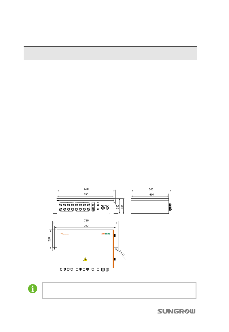
4.2.1 Dimensions
Fig. 4-1 Dimensions of PVS
Pictures in this manual are indicative only! The real product you receive
may differ.
12
Page 17
User Manual 4 Installation Guide
4.2.2 Installation site requirements
With IP65 protection degree, the PVS can be installed outdoors. Please meet the
following requirements:
Dimensions and weight of PVS should be considered sufficiently).
Ambient temperature -40℃~+70℃; Relative humidity 0~99%.
Installation site should be as close as possible to PV arrays for minimum cables
and wires usage.
Installation site should be safe venting.
PVS must be installed vertically, including following two types:
− Wall-hung type: Fix the PVS onto a wall (recommended).
− Pillar-mounted type: Fix the PVS onto a pillar.
Never install the device in direct sunlight to guarantee optimal performance.
For big PV plants, it is suggested that the device is installed on the back side of
PV arrays.
For better heat dissipation and convenient maintenance, enough space must be
maintained around the PVS.
For large-scale PV plant, install the PVS on the back of the PV cell installation
bracket
Humidity during installation may damage the PVS. Do not install the PVS
during rainy or humidity days.
Screw the water-proof terminals tightly to prevent moisture penetration no
matter the installation is vertically or horizontally. Seal the unused
terminals after cable connection.
Cover the water-proof lock core. Fix the lock protection device and the
device cabinet tightly by screws when PVS is installed in rooftop
horizontally.
4.2.3 Preparation before Installation
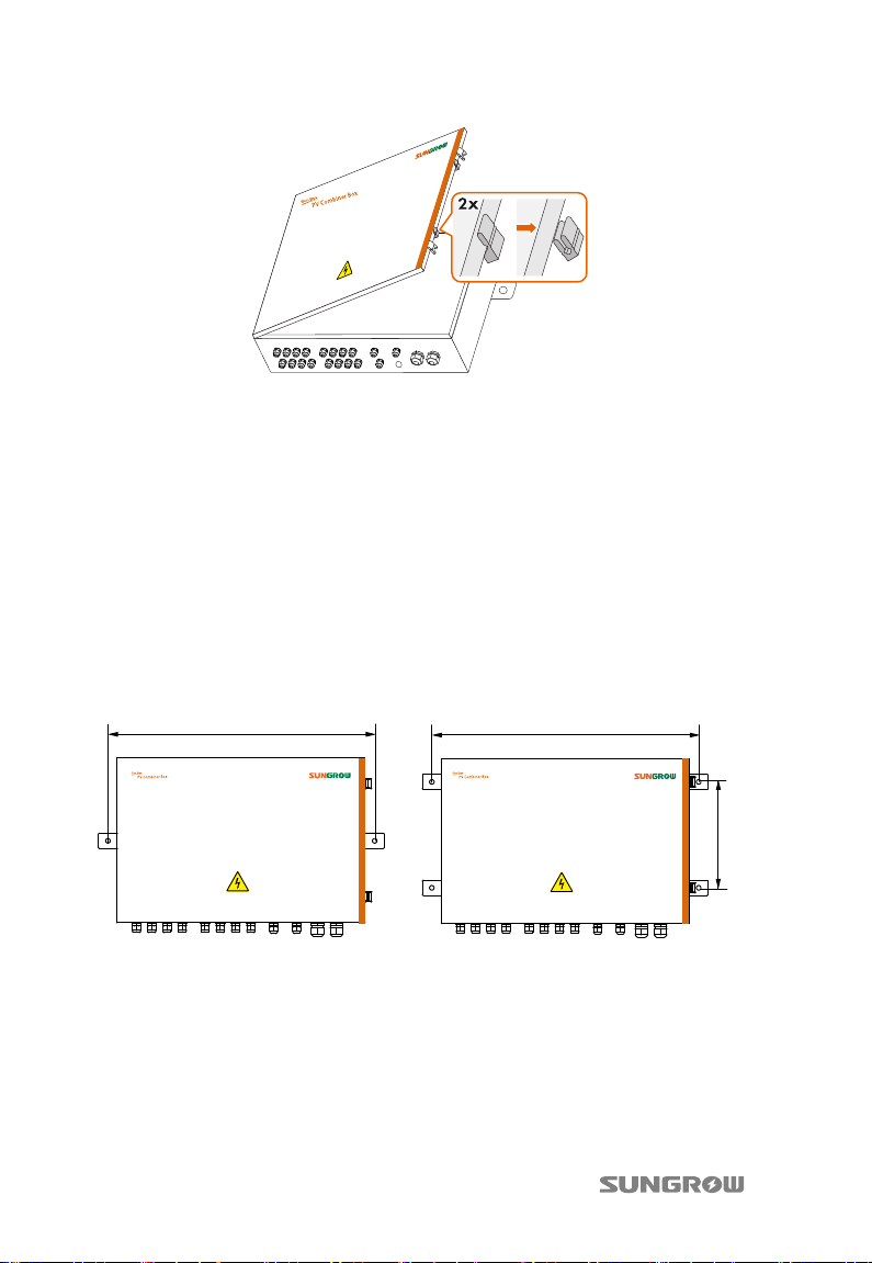
PVS is equipped with plastic buckle on the cabinet before delivery.
The plastic buckle is functioned as a buffer to prevent the sealing strip from
scratches and damages.
Before installing the PVS, please proceed as follows to remove the plastic buckle.
13
Page 18
4 Installation Guide User Manual
If this plastic buckle is missing during transport, the normal function of the PVS is
not affected.
4.2.4 Installation Method
PVS has two installation methods: vertical installation and horizontal installation.
Solution 1: Horizontal installation
Horizontal installation is applied to distributed PV plant and on rooftop.
Horizontal installation steps
Step 1 Measure the distances of the hangers of the PVS and mark positions on the
installation surface.
700mm
Step 2 Fix the PVS to the surface according to the sequence of bolt, PVS hangers, fix
surface, flat washer, spring washer and nut. Torque:18N.m
700mm
290mm
Solution 2: Vertical installation
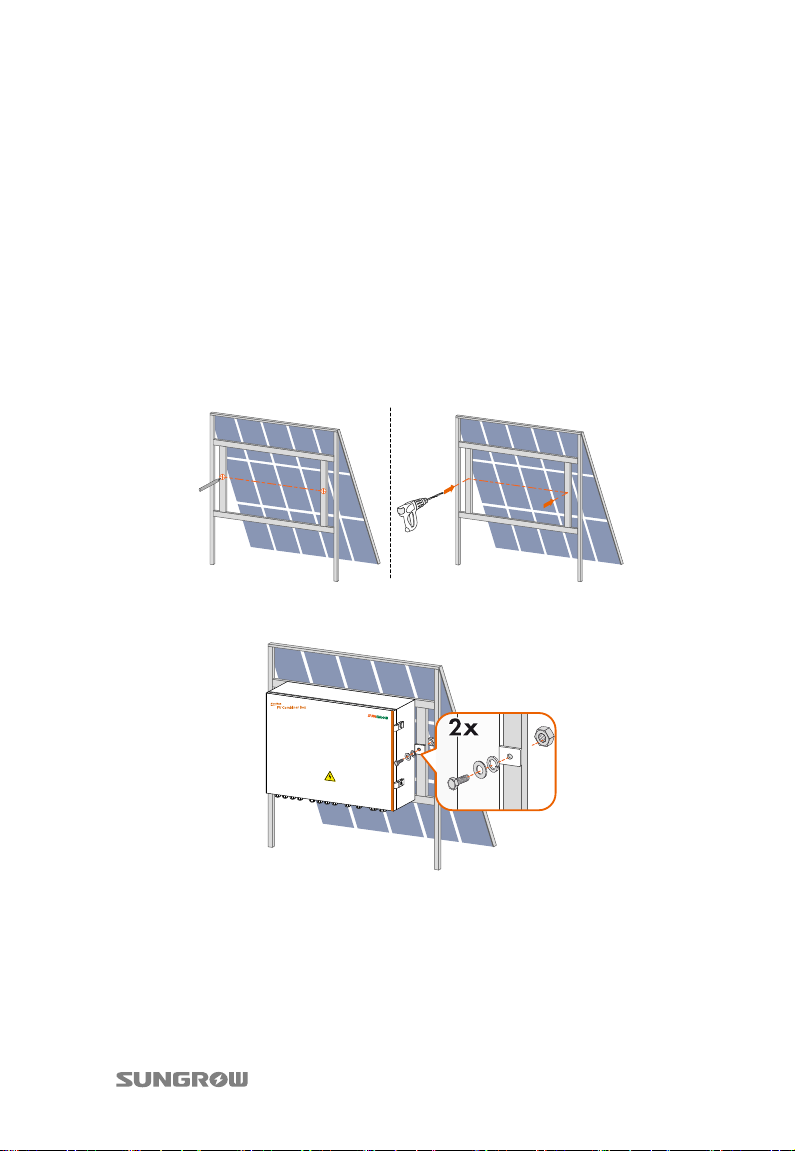
Vertical installation is applied to PV ground plant. PVS is installed in the shadow
place of the PV cells. Wall mounted or column mounted method can be adopted.
14
Page 19
User Manual 4 Installation Guide
Install PVS upside down is strictly forbidden.
Wall-mounted: fix PVS to the PV array’s installation frame through the mounting
holes of the PVS by 2 or 4 M10×30 bolts
Column-mounted: use hold hoop and steel angle as fixture to fix to the support
column. fix PVS to the steel angle through the mounting holes of the PVS by 2 or
4 M10×30 bolts
Installation steps:
Step 1 Measure the distances of the two hangers of the PVS.
Step 2 Mark positions according to the distances measured on the installation
surface and then drill holes.
Step 3 Fix the PVS to the surface according to the sequence of bolt, PVS hangers,
installation surface, flat washer, spring washer and nut. Torque:18N.m.
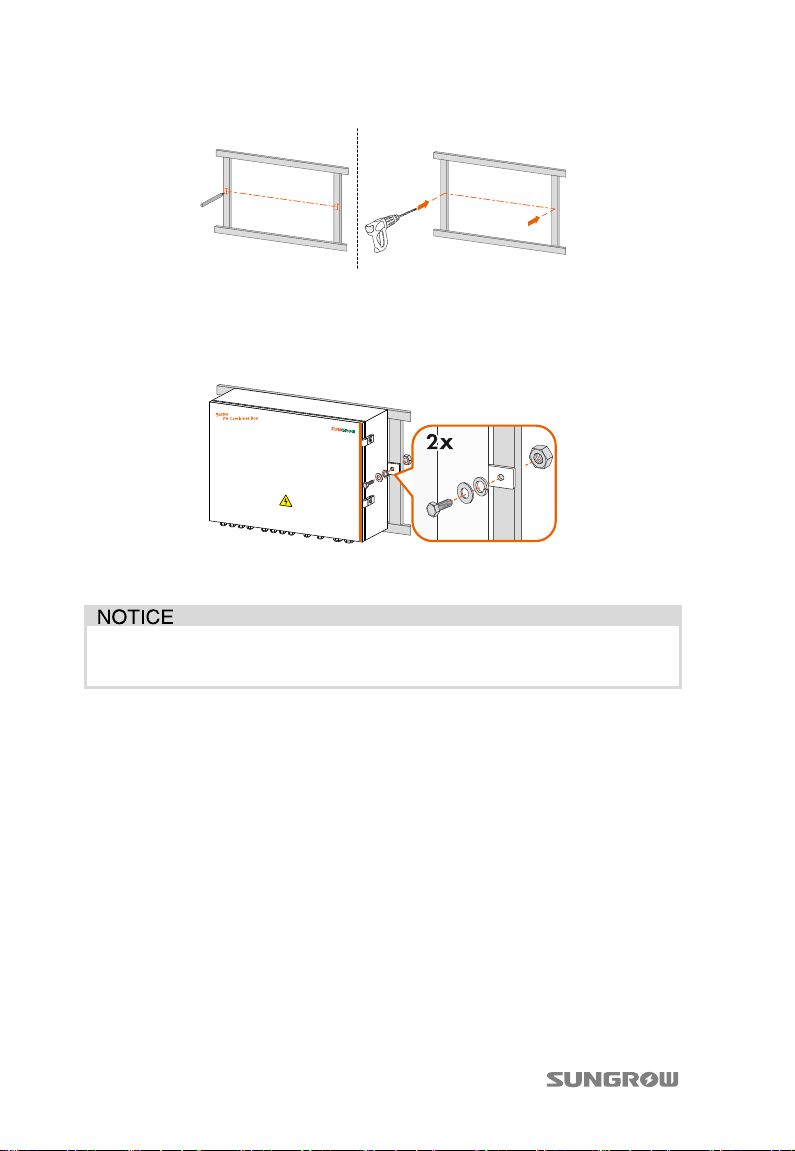
Column-mounted steps:
Step 1 The dimensions of the installation holes on the PV cell frame should meet the
requirements in Fig. 4-2.
15
Page 20
4 Installation Guide User Manual
Fig. 4-2 Drill holes (unit in mm)
Step 2
As shown in Fig. 4-3, install PVS by hexagon nut and hexagon bolt. From left
to right: bolt, PVS hangers, support, flat washer, spring washer and nut.
Tor que: 18N .m.
Fig. 4-3 Installation of PVS
Step 3
Check to ensure PVS is installed correctly and securely.
PVS can also be installed for roof application.
Observe all the instructions in this manual and relevant documents.
4.3 Electrical installation
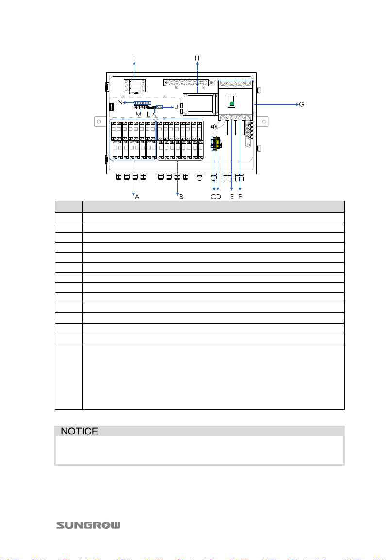
4.3.1 Internal structure
The internal structure of the PVS is shown below (take PVS-16M for example):
16
Page 21
User Manual 4 Installation Guide
No. Description
A DC+ fuse cartridge
B DC- fuse cartridge
C RS485 ports.
D Ground terminal
E Output of DC positive pole
F Output of DC negative pole
G DC switch
H Power board
I SPD
J Push switch (switch between current and communication parameter)
K Protocol switch (setting communication protocol)
L Dip switch (setting communication address)
M LED display (can display current, baud rate and communication address)
Indicators, from left to right:
TX: transmitted communication data signal indicator;
RX: received communication data signal indicator;
N
RUN: monitoring unit Run status indicator;
SPD: surge protection device Fault indicator;
CB: circuit breaker status indicator;
PWR: monitoring unit power supply status indicator.
Pictures above are for orientative information, and some details may not
exactly correspond to the product you received. Please prevail in kind.
4.3.2 Water-proof terminals and wirings
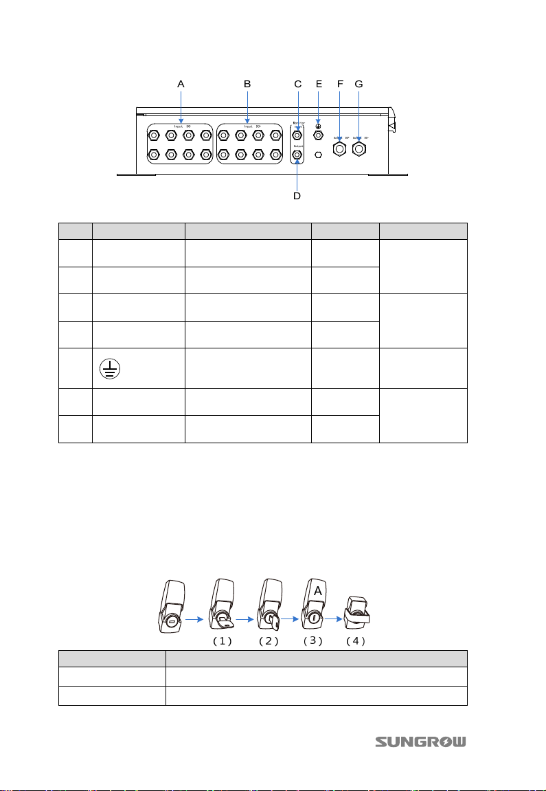
Water-proof terminals of PVS are shown in Fig. 4-4.
17
Page 22
4 Installation Guide User Manual
Fig. 4-4 Size and type of water-proof terminals
No. Label Description Model Cable(mm)
A INPUT DC+
B INPUT DC-
C Monitor Input
D Monitor Output
E
F Output DC+
G Output DC-
Positive pole input
waterproof terminal
Negative pole input
waterproof terminal
Communication input
waterproof terminal
Communication output
waterproof terminal
Grounding waterproof
terminal
Positive pole output
waterproof terminal
Negative pole output
waterproof terminal
M24*1.5
4~6
M24*1.5
PG-11
5~10
PG-11
PG-11 5~10
M32*1.5
12~25
M32*1.5
Note 1: Idle waterproof terminal not actually used shall be blocked inside the
box using fireproof mud.
Note 2: User can let 2 lines of input cables to share one waterproof terminal
according to actual demands.
4.3.3 Wiring preparations
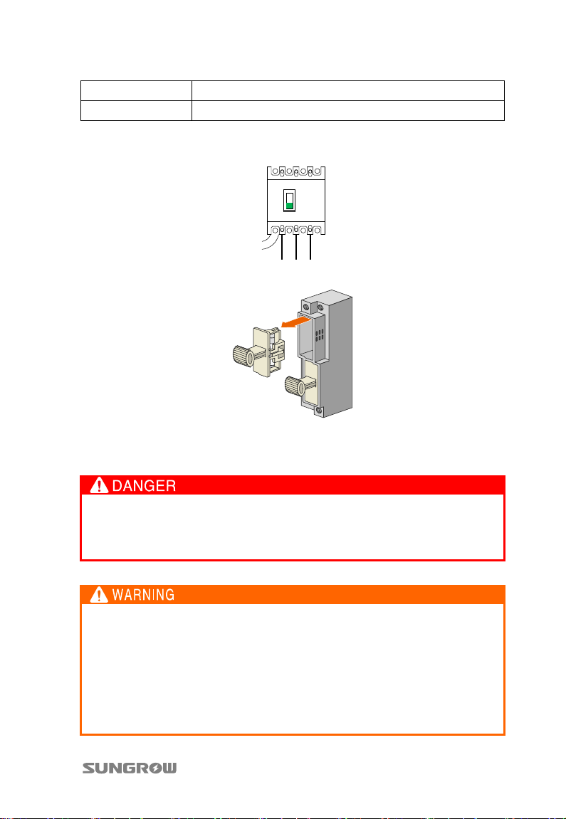
Step 1 Open the door
Step Operation
(1)
(2)
18
Insert key
Turn the key to vertical direction
Page 23
User Manual 4 Installation Guide
(3)
(4)
Step 2 Remove the protection cover.
Step 3 Turn the switch to “OFF” position.
Step 4 Remove fuse
Remove key
Pull down the metal buckle (“A” in above figure)
4.3.4 Input wiring and connections
High voltage is present inside the device!
Follow all the warning signs in the device.
Respect all the safety instructions in this manual and other documents.
Incorrect cable connection may cause damages to the PV cells, combiner
box and inverter. Respect the following instructions during cable
connection:
Connect by strictly following the circuit diagram;
Measure and make sure the string open-circuit voltage meets the
requirements of the combiner box before inserting the fuse;
Identify the positive pole and negative pole before connection.
19
Page 24
4 Installation Guide User Manual
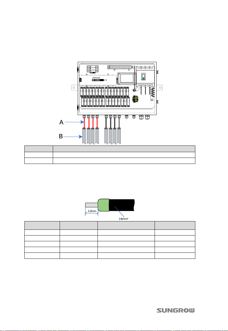
Step 1
Loosen the union nut of water-proof terminals.
Step 2 Insert the “PV1+” cable through terminals of positive input area, and connect
the cable to the “PV1+” terminal inside the device. Enough wire bending
space should be ensured.
No. Description
A Cable (e.g. “PV1+”, “PV2+”… “PV1-”, “PV2-” etc.)
B Conduit
Step 3 Strip off both protective and insulating layers with the help of a hand
crimping pliers.
Step 4 Select proper terminal to the corresponding cable. For example, LT160012,
16 stands for 16 mm
2,
the cross-sectional area of the crimping cable; 12
stands for 12mm, the length of the crimping tube, see the following figure.
Cross-section Terminal type Stripped length (mm) Force (N)
2.5mm2 LT025008 10±0.5 200
4mm2 LT040010 12±0.5 270
6mm2 LT060012 15±0.5 450
10mm2 LT100012 15±0.5 500
16mm2 LT160012 16±0.5 1500
Step 5 Stripped off the cable insulation layer, using wire stripper, to reveal the
copper core, length as specified in above table.
Notice: Do not break the copper wire during stripping.
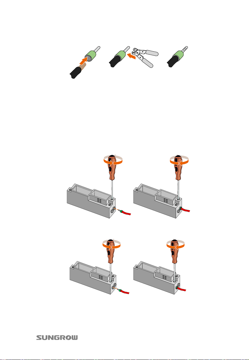
Step 6 Crimp the cable. Insert the stripped cable into the terminal. Crimp the cable
using special tool (mouth of the crimping plier should match the cable cross
20
Page 25
User Manual 4 Installation Guide
section), see the following figure.
Step 7 As shown in the following figure, connect the terminal to the corresponding
terminal of the combiner box.
Notice: press the bolt to the side with indentation during fixation. Make sure the
terminal is inserted into the combiner box as much as possible.
Step 8 Wiring: Press fit the cable with insulation layer stripped on the terminal at
bottom of the fuse box.
The cable connection of the upper layer is shown in the figure below (take the
connection method of the positive input for example)
− Cable connection method of the lower layer is shown below.
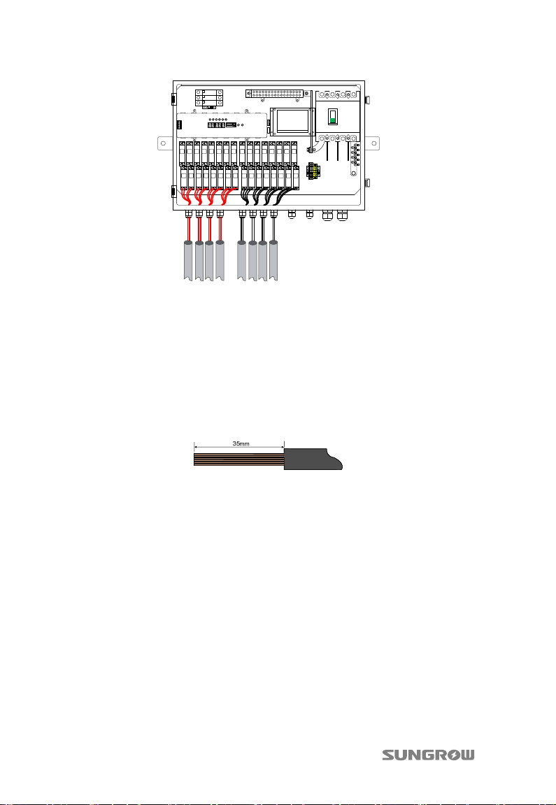
Step 9 Follow the same procedure to connect rest cables. Comb all the input cables
together with cable ties and firm them onto the cable support bar.
Appropriate cable bending space shall be ensured.
21
Page 26
4 Installation Guide User Manual
Fig. 4-5 Diagram of cabling route
4.3.5 Output wiring and connections
Step 1 Lift the protective cover upwards. Then loosen the nut from water-proof
terminals.
Step 2 Insert the “DC+” cable through “DC Output (+)” terminal. Enough cable
bending space should be ensured.
Step 3 Strip off both protective and insulating layers with the help of a hand
crimping pliers. The length of cable conductor shall be approx. 35mm.
Step 4 Connect cable conductor to certain DT terminal.
2
For PVS-8M, 50mm
For PVS-12M, 70mm
For PVS-16M, 90mm
terminal.
2
terminal.
2
terminal.
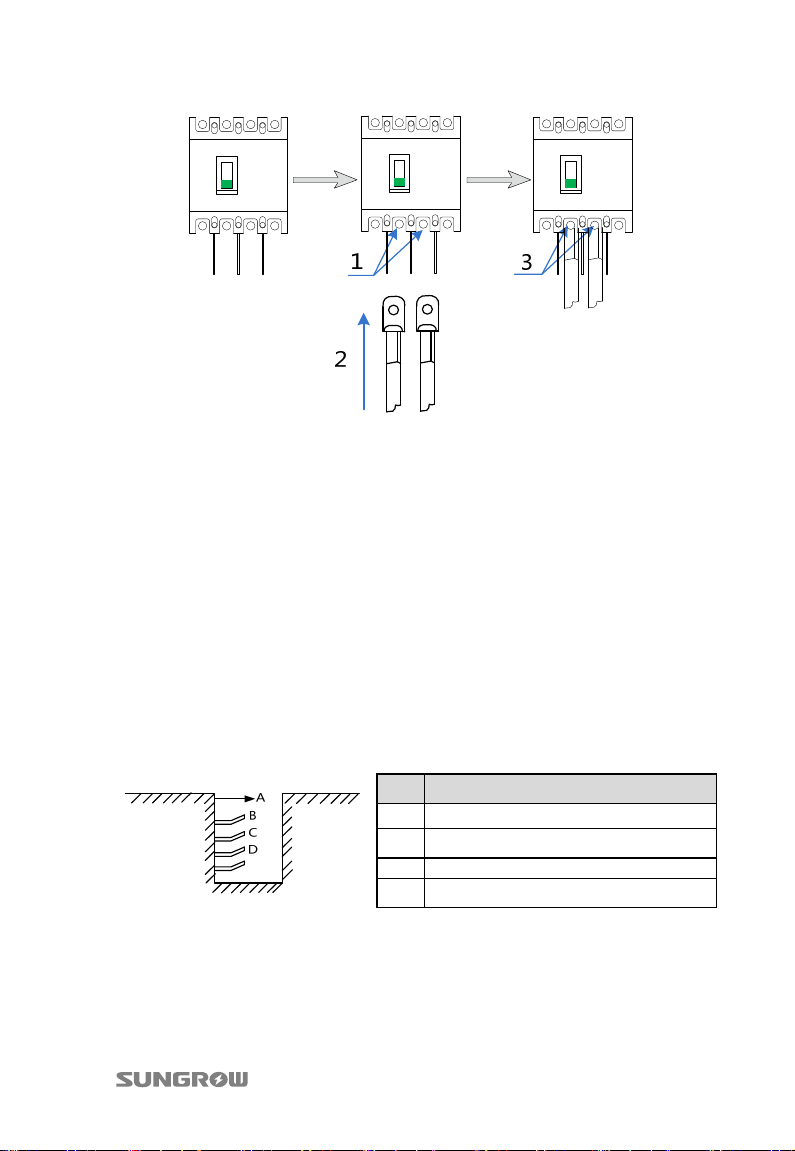
Step 5 Insert the DT terminal, and tighten the nut by using an inner hexagon
spanner. Firm cable onto the cable support bar. Appropriate cable bending
space shall be ensured.
22
Page 27
User Manual 4 Installation Guide
− 1. Use hexagon spanner to remove the nut;
− 2. Insert DT terminal into the output terminal;
− 3. Use hexagon spanner to tighten the nut.
Step 6 Screw the bolt of the water-proof terminal tight clockwise.
Step 7 Connect cable “DC-” to “DC Output (-)” following the procedures above.
Output wiring and connections have been finished.
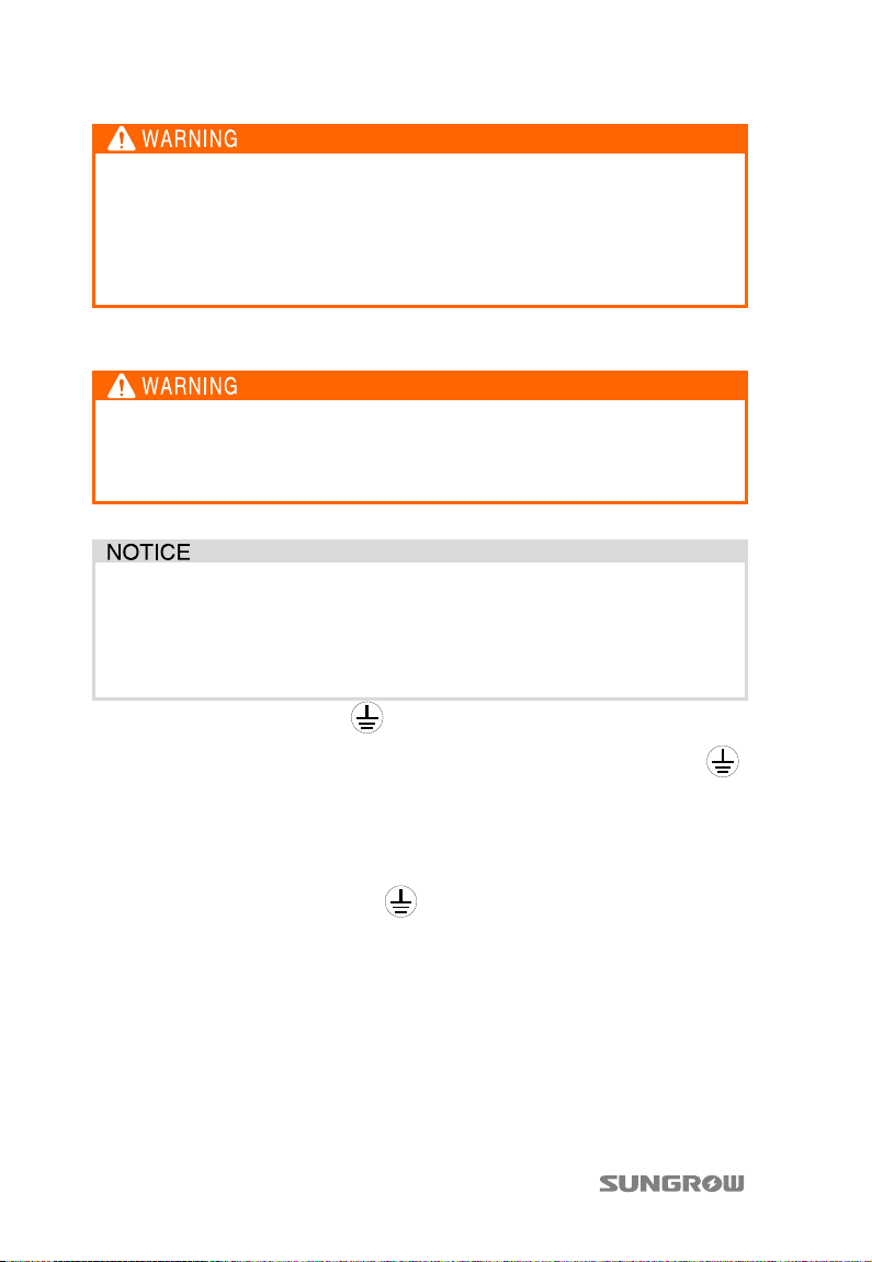
Step 8 Lay the cables connected the combiner box and external devices in the cable
trench for easy installation and maintenance. Cable trenches are designed
and constructed in accordance to related regulations and the number &
dimensions of the devices.
Step 9 Lay the combiner box positive and negative pole output cables,
communication cables in different layer of the support arm in the cable
trench to avoid short circuit caused by cable insulation layer cracks. See the
following picture; user can design the number of supporting arms as per
reality.
No. Name
A Cable trench
B Positive output cable supporting arm
C Negative output cable supporting arm
D Communication cable support arm
Cable trenches
Note: pictures here is indicative only, user can make adjustment according to real
needs.
23
Page 28
4 Installation Guide User Manual
Make sure that the nuts have been screwed into place. If the cable
conductor has not been connected firmly, long-time work may burn the
terminal. Stranded flame-retarded copper wire shall be used, and its size
shall be over the recommended value as described in 8.1.2.
Nuts of water-proof terminals must be screwed correctly and firmly.
Otherwise, water leakage can damage the PVS.
4.3.6 Ground wiring and connections
Ground cables shall be connected correctly and firmly. Otherwise:
The electric shock caused by a malfunction can lead to lethal damage.
The device can be damaged when lightning.
Relevant standards must be observed.
Ground cables must be connected firmly with both device and ground
terminals.
Ground resistance shall be measured after finishing ground connections,
and the measured values should not be over 1Ω.
Step 1 Loosen the union nuts of “ ” water-proof terminals.
Step 2 Insert the green-yellow wire from the device outside into the “ ”
Step 3 Strip off both protection and insulation layers, with approx. 12mm conductor
water-proof terminal, then pull the wire and connect it to the inner terminal.
Enough wire bending space should be ensured.
length.
Step 4 Loosen the tightening bolt of “ ” terminal with the help of a screwdriver.
Step 5 Insert ground cable through the opening and screw the tightening bolts
tightly. Firm the cable onto the cable support bar and enough cable bending
space shall be ensured.
Step 6 Tighten the nuts of water-proof terminal clockwise. Ground wirings have
been finished.
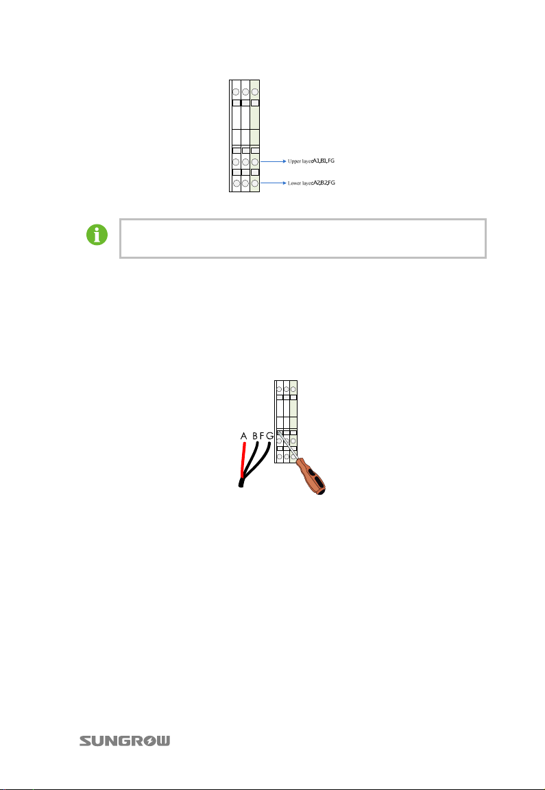
4.3.7 Communication Connections
Refer to the figure below for communication terminals inside the combiner box.
24
Page 29
User Manual 4 Installation Guide
Fig. 4-6 Communication connection
Upper terminal connects to input and lower terminal connects to
output. User may adjust according to real need.
Step 2 Unscrew the water-proof terminals “Monitor Input” and “Monitor Output”.
Step 3 Pull the communication cable inside the PVS through the water-proof
terminals.
Step 4 Strip off the cables’ protection layer and the insulation layer until the copper
core is 8mm outside.
Step 5 Insert the screwdriver inside the input cable terminal holes. Pull the
screwdriver until the leaf spring is bounced completely.
Step 6 Insert wires into bottom of wiring holes A1, B1, and FG. Among them:
− Connect communication cable RS485-A to A1;
− Connect communication cable RS485-B to B1;
− Connect communication cable shielding layer to terminal FG.
Step 7 Loosen the screwdriver to let the leaf spring connect to the cable.
Step 8 Follow the same steps to connect the output cables to the FG, A2 and B2 to
finish the communication terminal connection.
25
Page 30
4 Installation Guide User Manual
Communication cable must be shielded twisted pair cable. Communication
unstable or communication failure may follow if otherwise.
Communication cable should be far away from the high voltage cable. Place
the communication cables and power cables in parallel or strap them
together is strictly forbidden. Communication interface or device damage if
otherwise. If not prevented, lead the communication cable through
galvanized tube for shielding.
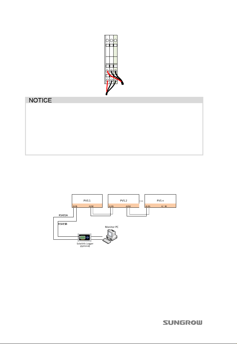
Communication solution
The communication method of PVS is shown below:
Fig. 4-7 Communication system connection
Connect A1 and B1 of first combiner box to A1 and B1 of data collector;
Connect A2 and B2 of first combiner box to A1 and B1 of second combiner box;
Connect A2 and B2 of second combiner box to A1 and B1 of third combiner box;
And so forth: connect A2 and B2 of previous combiner box to A1 and B1 of next
combiner box
26
Page 31
User Manual 4 Installation Guide
If the PVS is equipped with optional PV internal power supply, monitor can
wok normally when the PV voltage meet the switch power supply’s nominal
work power supply range.
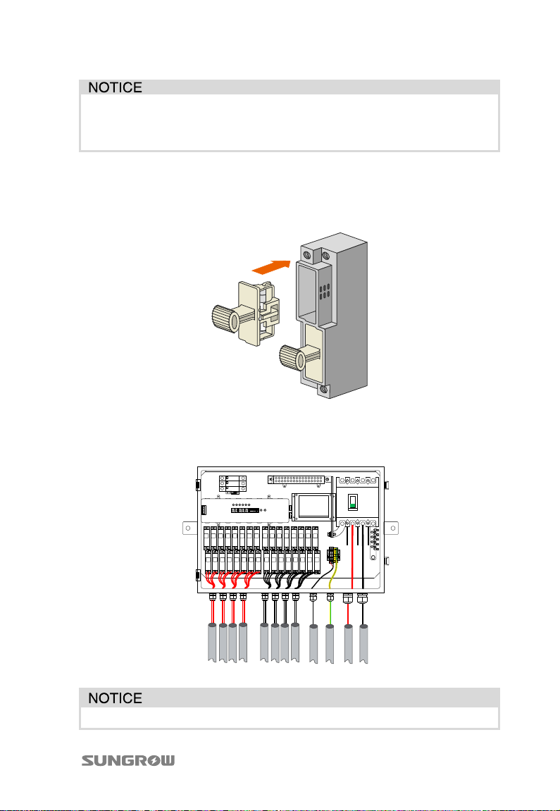
4.3.8 Installation of fuses
Proceed as follows to recover the fuse cover of the positive and negative input
terminal to its original place after cable connection.
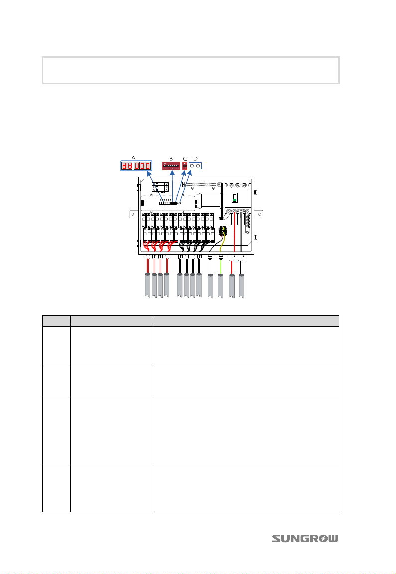
4.3.9 Bottom wirings
The bottom wirings are described in the following Fig. 4-8.
Fig. 4-8 Wiring connection illustration
After installation or commissioning, ensure the door and the cover of the
27
Page 32
4 Installation Guide User Manual
key is locked to avoid the water is in. If such a situation occurs, Sungrow
takes no responsibility for this.
4.4 Communication address settings
Communication parameters of combiner boxes can be set and viewed on the
monitoring unit, as shown below.
Fig. 4-9 Setting and inquiry of the communication parameters
No. Description Function
Used to display relevant electrical and
A LED digitron
B Dip switch
C Protocol switch
D Push switch K1, K2
28
communication parameters of combiner box. For
particular parameter inquiry method, refer to “Table
4-1”.
This switch adopts binary code from right to left, i.e.
bits 0-7 of binary address code. For setting method,
refer to “Table 4-2”.
Used to switch protocols. The first place switches
protocols:
“ON” for Modbus protocol;
“OFF” for Sungrow protocol
The second place is used to set branch connection
status.
Press push switch K1 to display string or combiner
box current voltage and current on the first places
of LED digitron. For method of operation, refer to
“Table 4-1”.
Press push switch K2 to display combiner box
Page 33
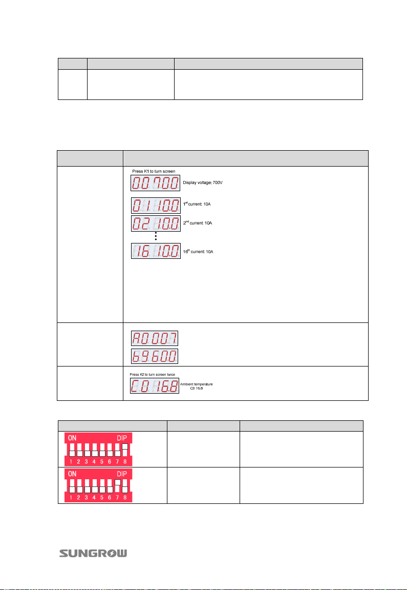
User Manual 4 Installation Guide
No. Description Function
communication address, baud rate, and chassis
temperature on the LED. For method of operation,
refer to “Table 4-2”.
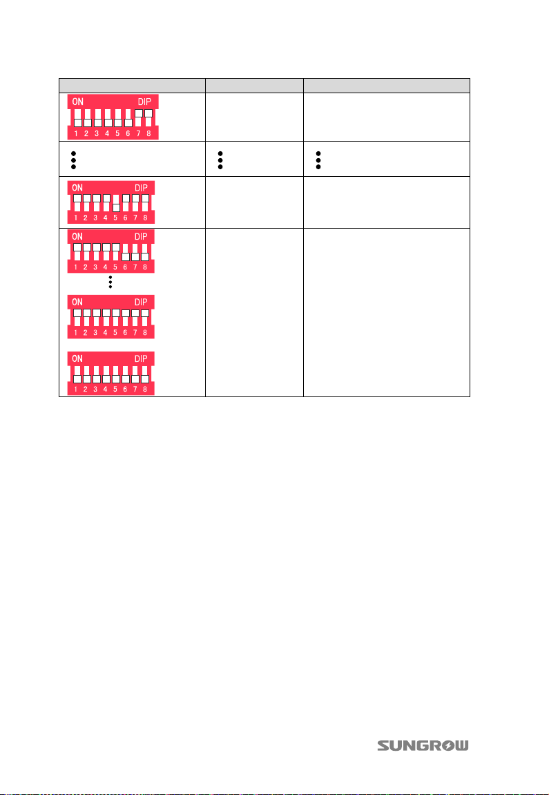
Combiner box allows inquiry of communication parameters by push switch. The left
switch is K1 and the right switch is K2. Particular definitions:
Tab. 4-1 Description of the function of inquiry by push switch (taking 16 lines as an
example)
Item Description
Voltage and
current display
Note: the LED display can be divided into the first two digits and last
three digits. The first two digits is used to display the N
PVS; the last three digits are used to display the current of this input.
For example: 0110.0 means that the current of the 1
th
input of the
st
input is 10A.
But when the first two digits are 00, the last three digits are the
voltage. For example: 00700 means that the present voltage is 700V.
Press K2 to turn screen once
Communication
display
Communication address
A0 007
Baudrate
b9600
Ambient
temperature
display
Tab. 4-2 Address-setting examples:
Dip-switch settings Binary address Decimal address
0000 0001
0000 0010
1
(1×2
2
(1×2
0
=1)
1
+0×20=2)
29
Page 34
4 Installation Guide User Manual
Dip-switch settings Binary address Decimal address
0000 0011
3
(1×2
1
+1×20=3)
1111 0111
If the code is:
1111 1000
1111 1001
……
1111 1111
or
0000 0000,
it is deemed
0000 0001
247
(1 ×2
2
1
7
+1× 26+1× 25+1× 24+0×
3
+1×22+1×21+1×20=247)
30
Page 35
User Manual 4 Installation Guide
Setting string input number
The standard types of Sungrow PVS are:
PVS-8M
PVS-12M
PVS-16M
If the strings input are 8, 12 or 16, there is no need to set any parameter.
This section introduces the communication setting method of the PVS when the
string inputs are 15 (the product user received is PVS-16M).
If the real strings input do not correspond to the abovementioned input number, set
the parameters according to the following steps to ensure the normal
communication of the PVS.
Step 1 After power on, the monitoring board on the top left of the PVS internal
works normally.
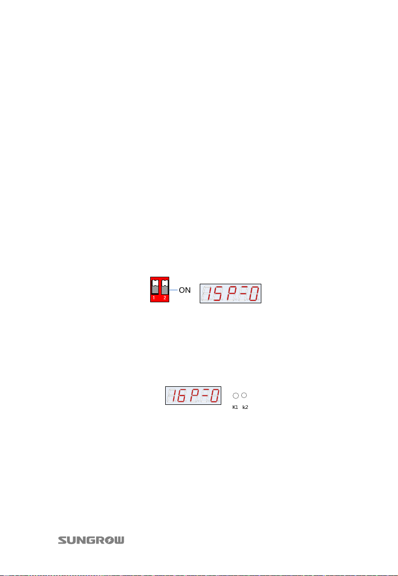
Step 2 Set the protocol switch 2 to the ON position. If the last three digits of the LED
are “P=0” or “P=1”, the PVS is in Setting status as shown below.
Step 3 Press the key switch A1 to select the input string number, for example 15.
Step 4 Press the key switch A2 and turn the last digit of the LED to “0”, i.e. “No input”.
− “0”: “No input”
− “1”: ”Input”
Take PVS with 15 inputs for example, the 16
LED is shown as below.
Step 5 After setting, turn the protocol switch 2 to the OFF position to save the above
settings.
th
input needs to be set to “No input”. The
4.5 Start/Stop of operation
PVS runs automatically when power on and stop when power off. User can control
the DC output of the PVS manually through the PVS internal DC switch.
31
Page 36
5 Commissioning
Check if the PVS can operate normally after installation:
Step 1 Connect the connection terminal of each PV string.
Step 2 Measure the input voltage of positive pole and negative pole of each input
to make sure they are basically same and the positive pole and negative pole
are connected correctly.
Step 3 Fasten the fuse holder.
Step 4 Close circuit breaker; monitoring unit power indicator “PWR” lights up and
status indicator “RUN” flashes. When push switch K2 is pressed, if there is a
value on the LED digitron, the operation is normal.
Step 5 Lock the door, remove the key and tighten the key-hole water-proof cover.
32
Page 37
6 Routine Maintenance
Due to ambient temperature, relative humidity, windblown dust and vibrations,
components of PVS will get aging. It is necessary to do the routine maintenance
work periodically on the device.
Only qualified electricians can do the maintenance work described in this
chapter.
After the maintenance work finished, be sure not to leave screws, washers
and the like in the PVS. The device can be damaged!
Only work on the PVS when it is switched off and voltage free. Fuses are
non-resetting once they are broken. After many times replacement, the fuse holders
will get loose. Users should fasten the fuse holders periodically to ensure valid
connections.
6.1 Replace the Fuse
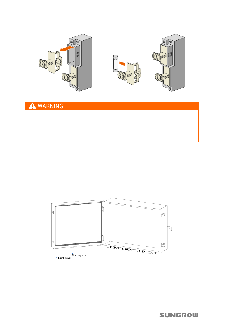
Method to replace fuse:
Step 1 Remove fuse cover
Step 2 Replace the fuse by a new one
Step 3 Restore fuse cover
33
Page 38
6 Routine Maintenance User Manual
Fig. 6-1 Replace the fuse
Tighten the fuse cover after replacing the fuse.
Disconnect the DC switch before checking and replacing fuse. Please notice
that high voltage still exist in all terminals of the DC switch. Make sure the
current of each input is zero by pliers and then replace the fuse.
6.2 Replace the sealing strip
The sealing strip inside the PVS is located in the PVS internal door cover as shown in
the following figure. It is advisable to check this sealing strip once every month. If it
is damaged by non-human factors, please contact Sungrow immediately to replace
the PVS door cover.
34
Page 39
7 Troubleshooting
This chapter gives the basic troubleshooting methods for customer as a reference.
7.1 Before troubleshooting
Please notice the following items before troubleshooting:
Disconnect the DC switch before operation.
Please do not touch the bare metal parts of the copper bar under the protection
plate.
Pull the fuse holder for maintenance of the combining busbar and to disconnect
the input cable.
High voltage still exists after DC breaker is switched off.
The fuse holders are still live after fuses are removed.
7.2 Common faults and troubleshooting
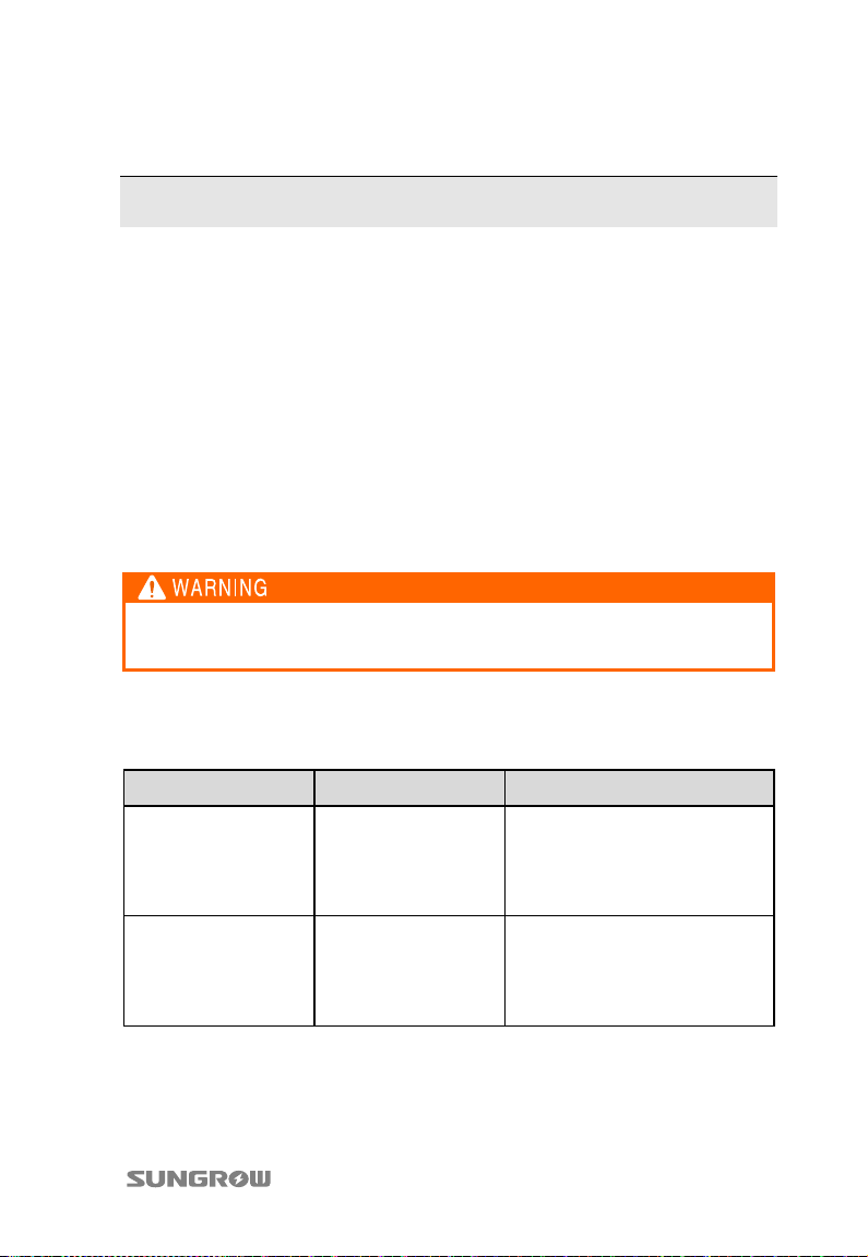
Fault Possible cause Method of correction
On the monitoring
unit, neither “RX” nor
“TX” lights up.
On the monitoring
unit, “RX” flashes and
“TX” does not light up.
35
RS485 communication
fault
Incorrect address
Check communication line.
Refer to “4.4 Communication
address settings”.
Use dip switch to set address
again.
Page 40
7 Troubleshooting User Manual
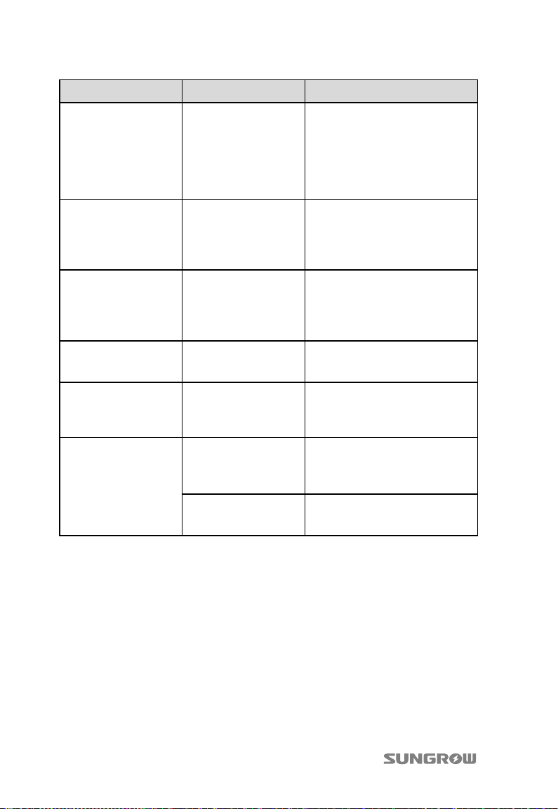
Fault Possible cause Method of correction
Twisted pair shielded cable shall
be used, with shielding layer
Communication
failure sometimes
Disturbance to
communication line
grounded. Install a 120Ω resistor
between communication
terminals A2 and B2 of the last
combiner box. Refer to “4.3.7
Communication Connections”.
Check voltage on monitoring
On the monitoring
unit, indicator “PWR”
does not light up.
No 5V output on
switching power
supply board
unit +5V plug, which shall be
about 5V; otherwise switching
power supply board is faulty and
please contact us for repair.
On the monitoring
unit, indicator “RUN”
does not flash.
On the monitoring
unit, indicator “SPD”
lights up.
Current of a branch
apparently smaller or
larger than current of
other branches
Display of open circuit
fault of a branch
Faulty CPU board
Failure of surge
protection device
Abnormal current
No PV string
connected to this
branch
Dropped out cable or
molten fuse
Contact us for replacement of the
monitoring unit
Replace surge protection device
in time
Check size of PV strings of this
branch for consistency.
Check if this branch has shaded
PV string.
Be referencing section “4.4
Communication address
settings”, set this branch to
unconnected status.
Check PV cables for
disconnection.
Or, replace fuse.
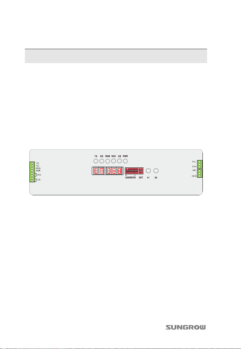
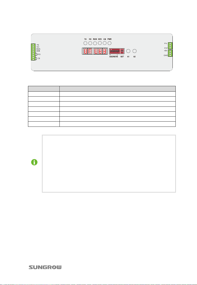
The following figure illustrates terminals and layouts of metering board.
36
Page 41
User Manual 7 Troubleshooting
Tab. 7-1 Descriptions
Indicator Meaning
TX Transmitted communication data signal indicator
RX Received communication data signal indicator
RUN Monitoring unit running status indicator
SPD Surge protection device fault indicator
CB Circuit breaker status indicator
PWR Monitoring unit power supply status indicator
+5V +5V plug on the monitoring unit
If you have any doubt during use of this product, please feel free to
contact us.
After-sales service telephone: 400-880-5578
E-mail: [email protected]
For contact, please provide the following information so that we can
provide you with help and service more quickly:
Combiner box model
Combiner box serial number
Brief description of fault information
37
Page 42
8 Appendix
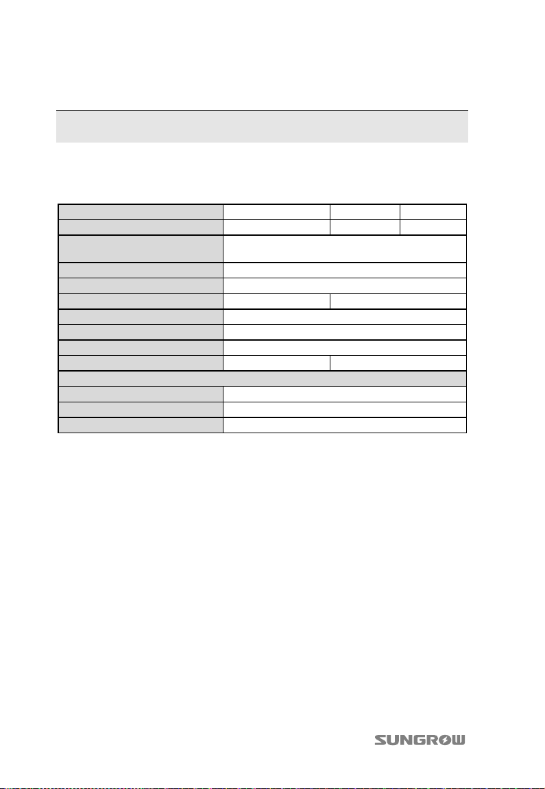
8.1 Technical data
Types PVS-8M PVS-12M PVS-16M
Max. string number
Input current range
Max DC voltage
Communication
Power for communication
Degree of protection
Ambient temperature range
Relative humidity
Weight approx.
Optional components
String monitoring
Switch work state monitor
Communication port
8 12 16
Refer to nameplate (the value can be changed by
replacing fuses)
200Vdc~1000Vdc
RS485
2.5W 3W
IP65
-40℃~+70℃
0~99%
27kg 29kg
Yes
Yes
RS485
38
Page 43
User Manual 8 Appendix
8.2 Cable requirements
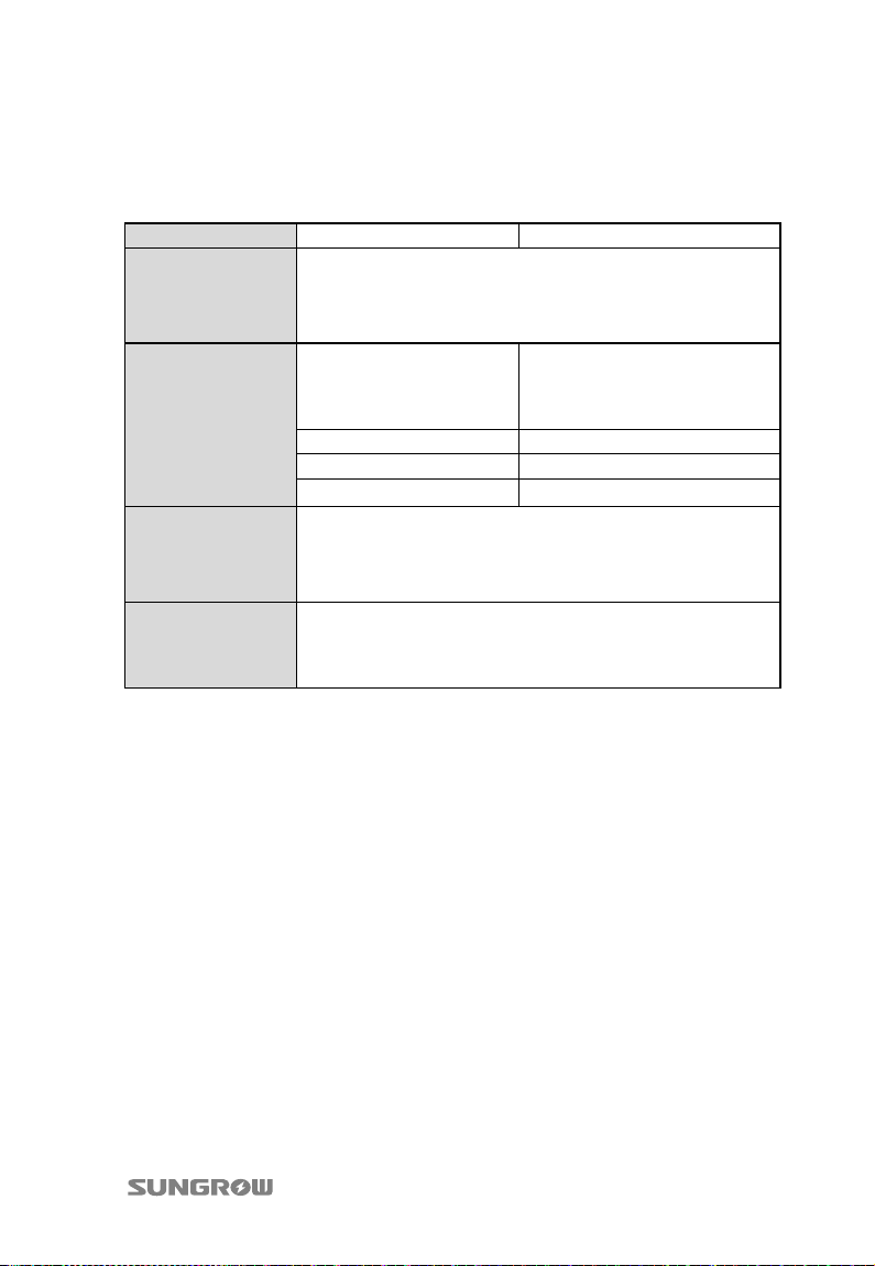
Types PVS-8M PVS-12M/PVS-16M
Type: 4 mm2~6mm2 Stranded flame-retarded copper wire
Input cable
Output cable
Communication
cable
Grounding
terminals
Stripped length: 10mm
Bolt: M4
Tightening torque: 1.5N.m
Type:
2
50mm
Stranded
flame-retarded copper
wire
Stripped length: 35mm Stripped length: 35mm
Bolt: M10 Bolt: M10
Tightening torque: 20N.m Tightening torque: 20N.m
Type: 1.5mm2 Four core STP with low resistance
Stripped length: 7mm
Bolt: M3
Tightening torque: 0.6N.m~0.8N.m
Type: 16mm2 Stranded flame-retarded copper wire
Stripped length: 15mm
Bolt: M6
Tightening torque: 4N.m
Type:
2
70mm
or 90 mm2 Stranded
flame-retarded copper wire
8.3 Quality Assurance
Where any fault occurs during the warranty period, Sungrow will maintain or replace
the product for free.
Evidence
Sungrow Power Supply Co., Ltd. needs the users to provide the receipt invoice and
the date you purchase. Meanwhile the trademark should be clearly legible.
Otherwise Sungrow Power Supply Co., Ltd. has the right to exclude liability claims.
Conditions
The original unqualified product should return to Sungrow.
Users should permit appropriate time to maintenance the device with fault for
Sungrow.
39
Page 44
8 Appendix User Manual
Exclusion of liability
Guarantee or liability claims for damages of any kind are excluded if they are caused
by one or more of the following:
Improper, inappropriate use or installation of the product
Installing or operating the product in an inappropriate environment
Installing or operating the product when ignoring relevant safety regulations in
the deployment location
Ignoring safety warnings and instructions in all documents relevant to the
product
Installing or operating the product under incorrect safety or protection
conditions
Altering the product or supplied software without authorization
The product malfunctions due to operating attached or neighboring devices
beyond permissible limit values.
In case of unforeseen calamity or accidents
Where fault is caused by any of the above and users have the relevant demand,
Sungrow will do the paid maintenance work to the device after judgment.
Specifications subject to change without notice.
40
Page 45

User Manual 8 Appendix
8.4 About us
Sungrow power supply is a china-leading manufacturer of various power electronics
products for renewable energy generation systems. Our products include converters,
inverters, battery chargers, and other power supplies for distributable generation
system in both grid-connected and stand-alone applications. The power rating of
Sungrow products covers from several hundred watt to large mega-watt systems.
The pursuit of Sungrow is to help our customers acquire stable and clean power
with minimum cost, maximum reliability and enhanced safety.
41
Page 46

8 Appendix User Manual
42
 Loading...