

Page 1
SH3.6_4.6K-QUEN-Ver14-201805 Version:1.4
Quick User Manual
SH3K6 / SH4K6
Grid-Connected Hybrid Inverter
Page 2

Page 3

I
All Rights Reserved
No part of this document can be reproduced in any form or by any means
without the prior written permission of Sungrow Power Supply Co., Ltd.
Trademarks
and other Sungrow trademarks used in this manual are
owned by Sungrow Power Supply Co., Ltd.
All other trademarks or registered trademarks mentioned in this document are
owned by their respective owners.
Notice
In no case shall this manual substitute for the user manual or related notes on
the device.
Contents will be periodically updated or revised due to product development.
The information in this manual is subject to change without advance notice!
Make sure to read over, fully understand and strictly follow the detailed
instructions in the user manual and other regulations before installation. Any
violation could result in personal death, injury or damage to the device.
The latest manual can be acquired at www.sungrowpower.com.
Contact Information
Should you have any questions about this product, please contact us:
Company:
Sungrow Power Supply Co., Ltd.
Website:
www.sungrowpower.com
E-mail:
Address:
No. 1699 Xiyou Rd.,
New & High Technology Industrial
Development Zone, Hefei, P. R. China.
Zip:
230088
Telephone:
+86 551 6532 7834, +86 551 6532 7845
Fax: +86 551 6532 7856
Page 4
II
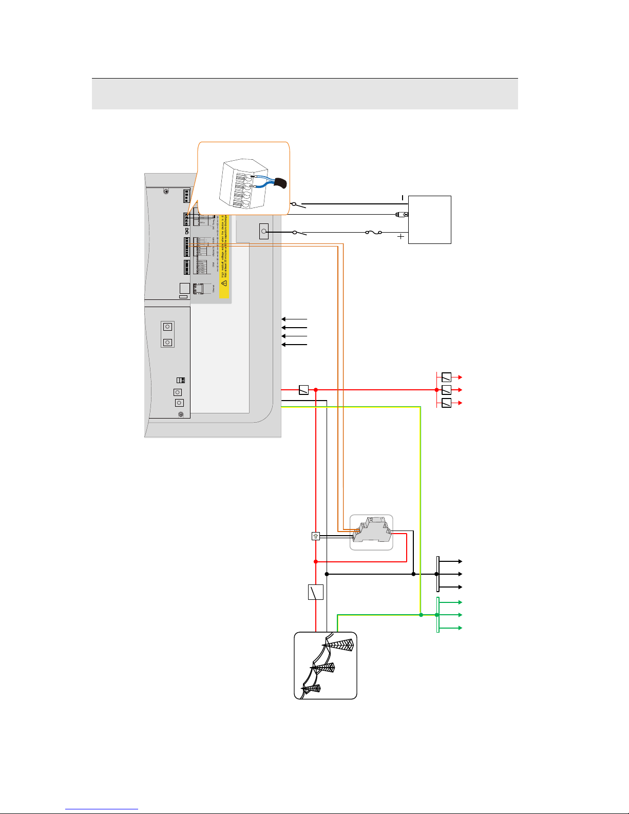
System Overview
Fuse
(
optional)
※ Installation of the copper is required in case of parallel PV input.
L
A
PV1 PV2
B
L
N
N
PE
PE bar Neutral bar Home appliance
Main Switch
SUNGROW meter
Utility Grid
Copper
A2 B2
1-phase sensor
Li-ion
battery
※
Circuit
breaker
Wiring diagram for a single-phase system with a Li-ion battery (CAN communication)
Inverter inside
The CT clamp of 1-phase sensor can be placed before or after the main switch.
CANH
CANL
BAT_Com.
Page 5

III
Wiring diagram for a three-phase system with a Li-ion battery (CAN communication)
※
Installation of the copper is required in case of parallel
PV input.
L3
N
PE
PE bar Neutral bar
Home appliance
Main Switch
AC circuit breaker
Utility Grid
Copper
※
L1
L2
IN
OUT
A2 B2
Fuse
(optional
)
Li-ion
battery
CANH
CANL
SUNGROW
meter
A
B
Load side
Grid side
Inverter inside
PV1 PV2
CANH
CANL
BAT
_Com
.
Page 6
IV
Wi-Fi
Ethernet
Monitoring
Earth Fault Alarm
NO2
COM2
Router/Switch
Direct mode
SolarInfo Moni APP
SolarInfo Bank Server
SolarInfo Bank
Webserver Explorer
SolarInfo WiFi
Light
Buzzer
240V AC
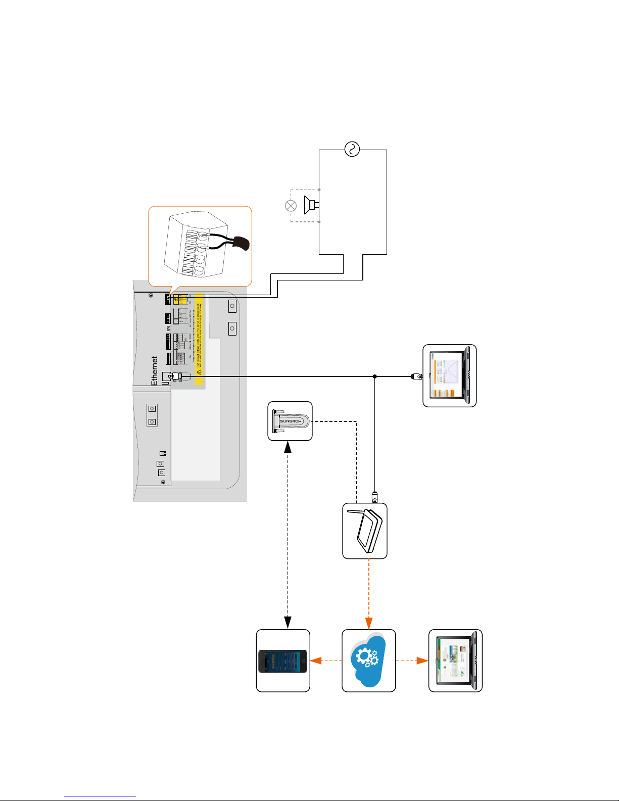
2. The buzzer inside the inverter will beep if an
earth fault occurs.
Notice:
Inverter inside
DO1
COM1
NO1
DO2
COM2 NO
2
1. The earth fault alarm can also be sent to your
email by the SolarInfo Bank server.
Page 7

V
Copper
A2 B2
※
Fuse
(optional)
※ Installation of the copper is required in case of parallel PV input.
L
A
PV1 PV2
B
L
N
N
PE
PE bar Neutral bar
Home
appliance
Main Switch
Utility Grid
1-phase sensor
Li-ion
battery
PV
inverter
Circuit
breaker
Retrofitting the existing PV system at a single-phase system
Inverter inside
The CT clamp of 1-phase sensor can be placed before or after the main switch.
CANH
CANL
Page 8
VI
※ Installation of the copper is required in case of parallel PV input.
Inverter inside
L3
N
PE
PE bar Neutral bar
Home appliance
Main Switch
AC circuit breaker
Utility Grid
Copper
※
L1
L2
A
B
A2 B2
Fuse
(optional)
Sungrow
battery
CANH
CANL
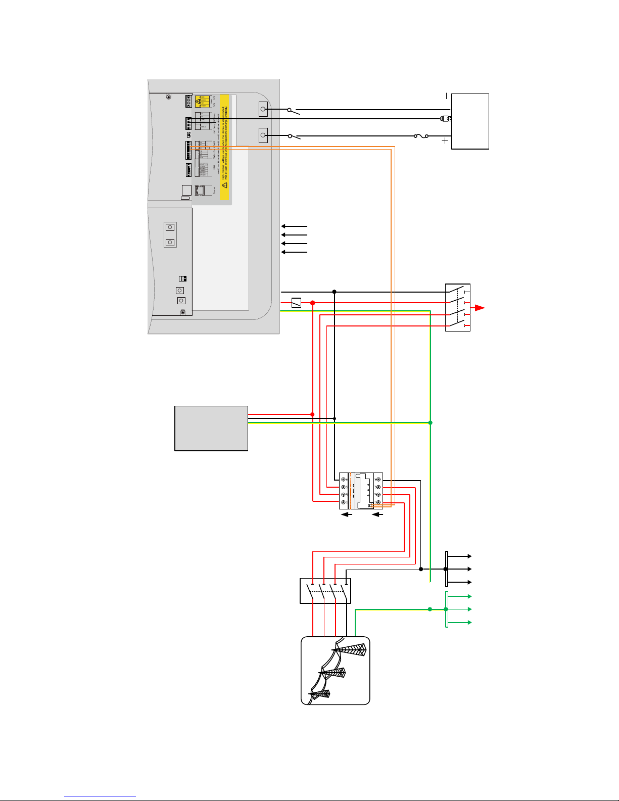
Retrofitting the existing PV system at a three-phase system
PV
inverter
IN
OUT
SUNGROW
meter
Load side
Grid side
PV1 PV2
Page 9

VII
Contents
System Overview ..................................................................... II
1 Installation ......................................................................... 1
1.1 Location Requirements ............................................................. 1
1.2 Installing the Inverter ................................................................. 2
1.3 Grounding the Inverter .............................................................. 3
1.4 Installing the Meter .................................................................... 4
2 E lectrical Connection ........................................................ 5
2.1 Terminal Description .................................................................. 5
2.2 Meter Connection ...................................................................... 6
2.3 Grid Connection ...................................................................... 10
2.4 PV Connection ........................................................................ 11
2.5 Communication Connect ion .................................................... 12
2.6 Battery Connection .................................................................. 13
2.7 DO Connection ........................................................................ 15
2.8 Retrofitting the Existi ng P V System ......................................... 16
2.9 Connecting to Interface Device for SPI (Italy) ......................... 17
3 Commissioning ............................................................... 20
3.1 Button Function ....................................................................... 20
3.2 Commissioning Procedure ...................................................... 21
3.3 Result Verification .................................................................... 25
4 SolarInfo Moni App Configuration ................................. 30
4.1 App Operation Requirements .................................................. 30
4.2 Installing the App ..................................................................... 30
4.3 Visiting in “Local Access” Mode ............................................... 31
4.4 Visiting in "[Login]" Mode ......................................................... 32
5 L CD Op er ation ................................................................. 33
5.1 Main Screen ............................................................................ 33
5.2 Viewing the Error Codes ......................................................... 34
Page 10

VIII
5.3
LCD Menu ................................................................................ 35
5.4 Setting the Country Code ......................................................... 36
5.5 Setting the Protective P ar ameters ........................................... 37
5.6 Setting the Communication Parameters .................................. 38
6 Troubleshooting .............................................................. 39
6.1 Troubleshooting of the Indicator ............................................... 39
6.2 Troubleshooting of the Errors ................................................... 39
7 Appendices ...................................................................... 48
7.1 Inverter Technical Data ............................................................ 48
7.2 Meter Technical Data ............................................................... 50
Page 11

1
1 Installation
1.1 Location Requirements
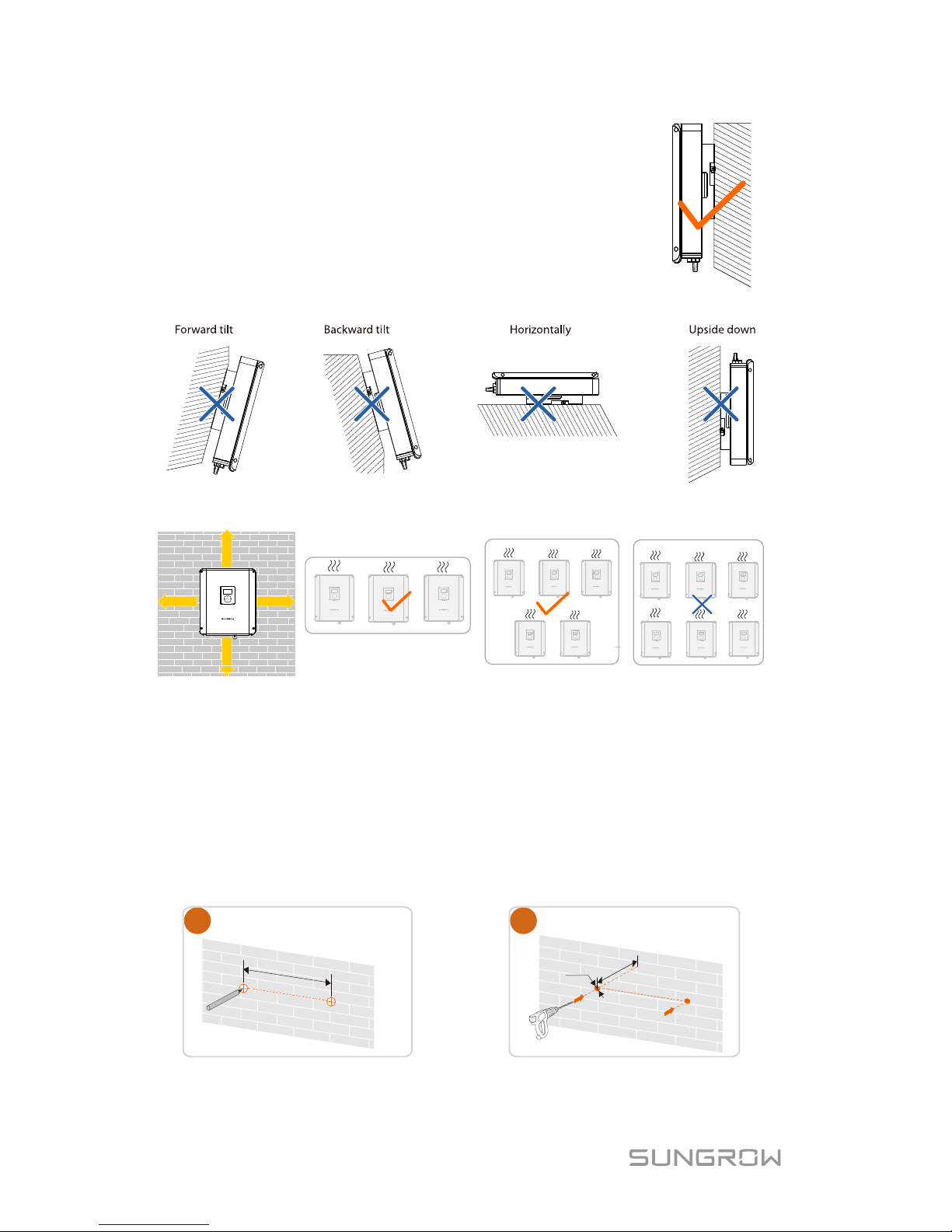
The concrete wall should be suitable for the weight and dimensions of the
inverter.
The location should be convenient for installation, cable connection and
service.
The location should be not accessible to children.
The location should be away from flammable materials or gas, and the
environment should not be enclosed.
Flammable wall
Flammable material or
gas near the installation
Closed cabinet
The shaded side of the building would be better.
Snow
accumulation
Direct rain fallDirect sunlight
Page 12
1 Installation Quick User Manual
2
Install vertically for sufficient heat dissipation.
Clearance requirements for single and multiple installation:
300mm
300mm
300mm
300mm
1.2 Installing the Inverter
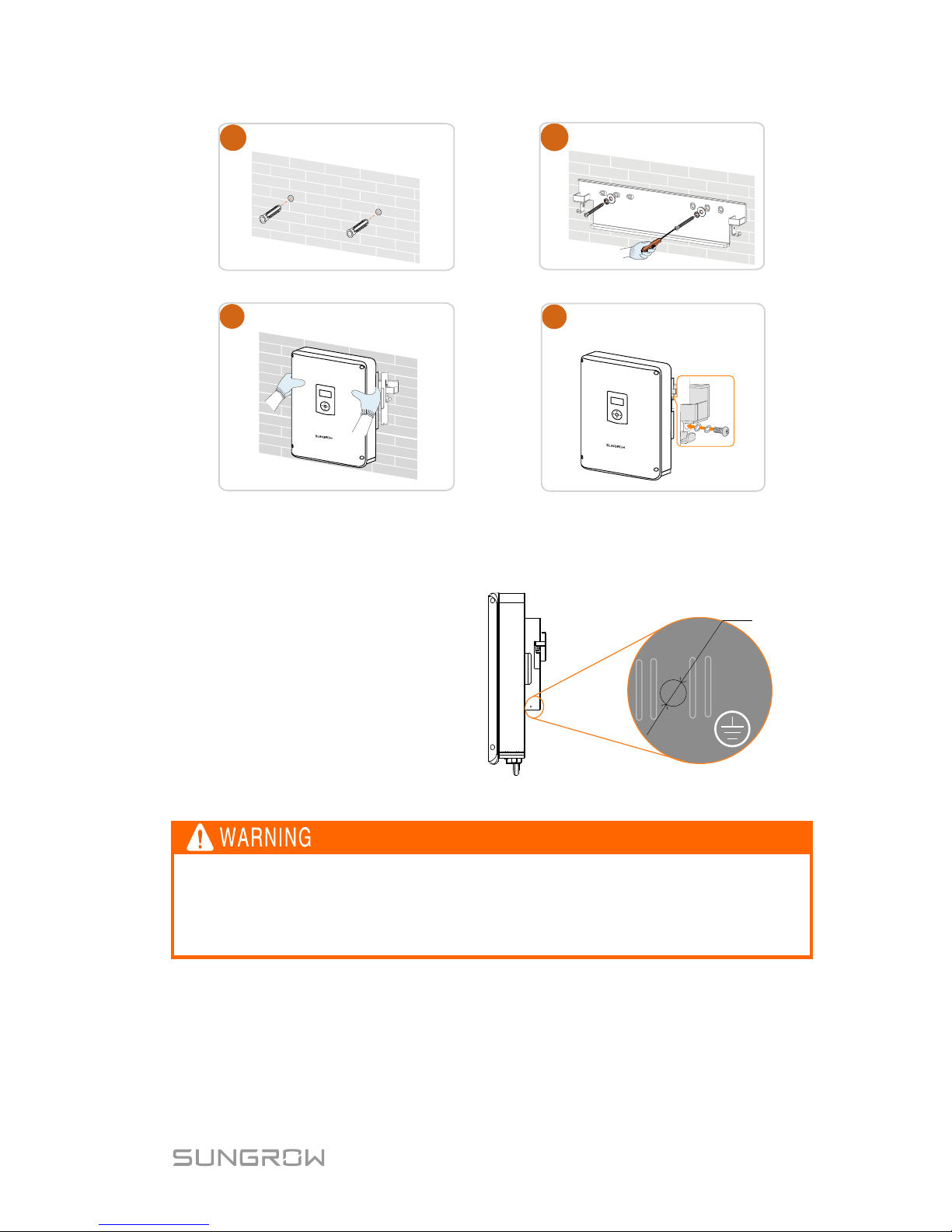
Install the inverter on the wall by means of the wall-mounting bracket and the
expansion plug sets.
The depth of the holes should be about 70 mm. Be sure to adhere to the
following screw assembly sequence: self-tapping screw, spring washer, fender
washer, wall-mounting bracket.
Mark the positions
1
φ10
Drill the holes
2
D 70 mm
240 mm
Page 13
Quick User Manual 1 Installation
3
Place the expansion
tubes
Secure the bracket
4
3
5
6
Mount the inverter to the bracket
Secure the inverter with two
M5 screws and washers
(3.
0 N.
m)
1.3 Grounding the Inverter
A second protective earth (PE)
terminal is equipped at the side
of the inverter. Be sure to
connect this PE terminal to the
PE bar for reliable grounding.
M5
Fig. 1-1 Second PE T erminal
In no case shall the second PE connection substitute for the PE
connection on th e terminal block of AC connector. Be sure to connect
both PE terminals for reliable grounding. The loss of any or all rights
may follow if otherwise.
Page 14
1 Installation Quick User Manual
4
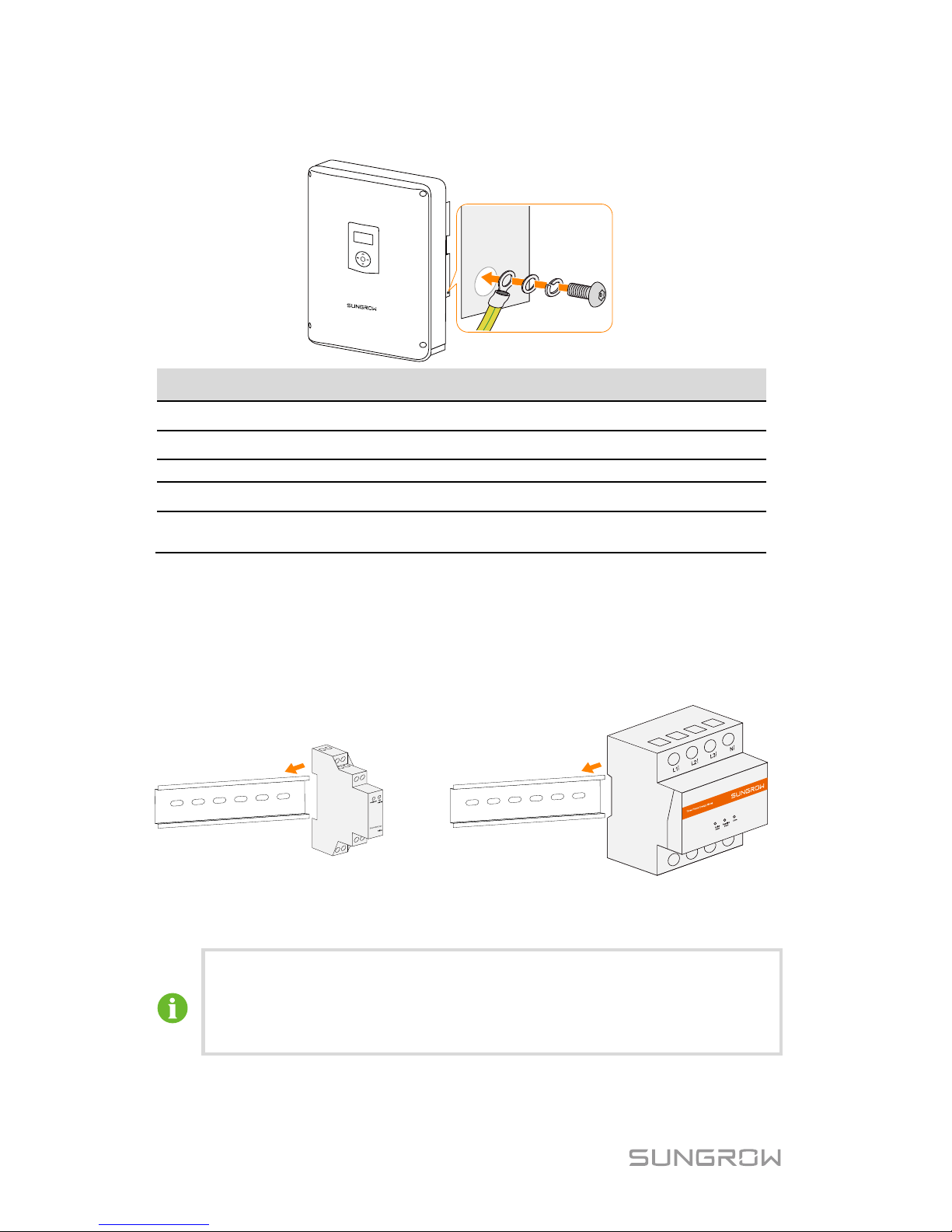
Second PE Connection
A
B
C
D
E
Item Description Specification
A Cable socket B Washer -
C
Spring washer
-
D Screw
M5 x 12 mm (3.0 Nm)
E Yellow-green cable
6–10 mm2 copper wire or 10–16 mm
2
aluminum wire
1.4 Installing the Meter
The SUNGROW meter should be installed nex t to t he main switch. It supports a
35 mm DIN-rail installation, as shown in the following figure.
Single-phase Energy Meter
Three-phase Energy Meter
Fig. 1-2 Installing the Energy Meter to the Rail
The single-phase Energy Meter and the three-phase Energy Meter
are alternative in the delivery. The meter figures in this document
have been created for the three-
phase Energy Meter unless
otherwise specified.
Page 15

5
2 Electrical Connection
For the TT utility grid, the N line v ol tage t o groun d must be l ess t han 3 0
V.
2.1 Terminal Description
Connection terminals on the inner configuration circuit board are shown below:
Fig. 2-1 Configuration Circuit Board Inside the Inverter
No.
Label
Connection
Tool Requirements
1
Copper
PV (for parallel mode)
Phillips screwdriver
2
Ethernet
Communication
-
3 DRM
Local control for SPI
(Italy)
Flat-head screwdriver
with an open end of 2
mm
4
DI
Reserved
-
5 RS485
A1, B1 for external
device,
A2, B2 for the meter
Flat-head screwdriver
with an open end of 2
mm
6
120 Ohm
RS485
-
7 BAT_Temp.
Temperature sensor
PT1000
Flat-head screwdriver
with an open end of 3
Page 16

2 Electrical Connection Quick User Manual
6
No.
Label
Connection
Tool Requirements
8
BAT_Com.
(CANH, CANL)
Battery communication
mm
9
DO1
Power management
10
DO2
Earth fault alarm
11
BAT+, BAT-
Battery
Phillips screwdriver
Terminals at the bottom of the inverter are shown below:
Backup Ctrl
Fig. 2-2 Terminals at the Bottom of the Inverter
Label
Description
AC-Grid
AC terminal to the utility grid.
Backup Ctrl
Reserved.
PV1+, PV1-, PV2+,
PV2-
Terminals for the DC cables.
ON, OFF
DC switch.
Com.
Cable glands for Ethernet, RS485, CAN, AI, DI and DO.
Wi-Fi
Terminal for the Wi-Fi module.
BAT+,BAT-
Cable glands for the battery power cables.
2.2 Meter Connection
The Energy Meter must only be connected to the distribution board of
household loads next to the main switch, as shown in the following figure.
Sungrow meter
Home Appliance
PV strings
A
Meter
link
Network
meter
Main
switch
Utility
grid
Solar switch
Inverter
Page 17
Quick User Manual 2 Electrical Connection
7
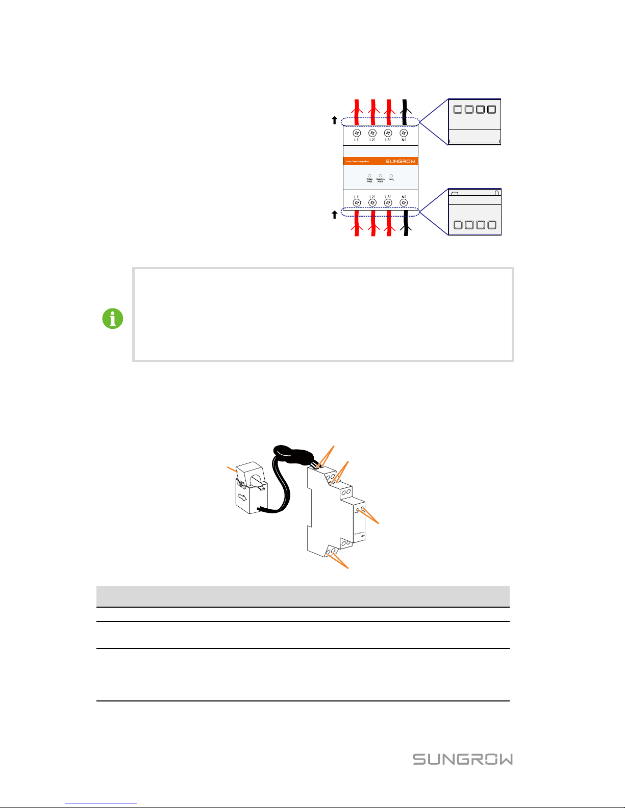
2.2.1 For Three-phase Energy Meter
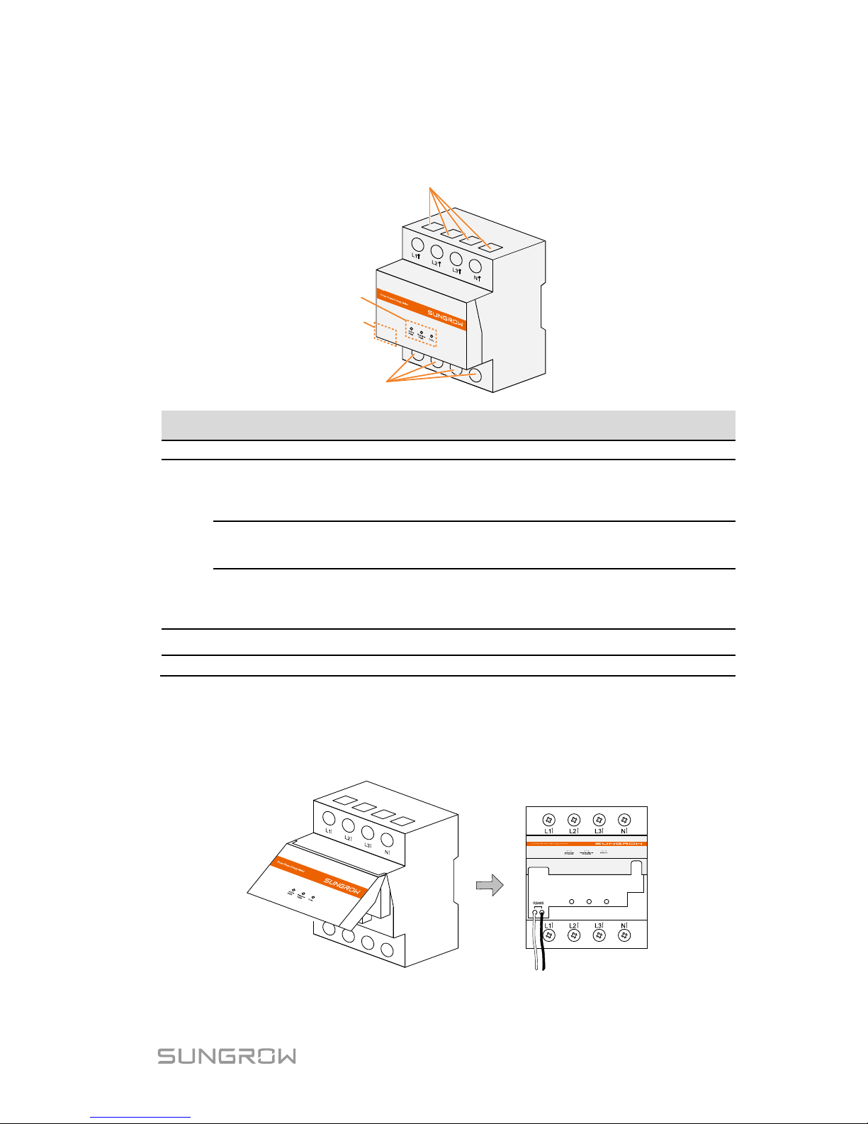
Three-phase energy meter and its terminals are shown in the following figure.
A
D
B
C
Designation Specification
A
L1, L2, L3, N
Output terminals to the load side
B
Active PWR
Glowing: 1000 impulse per kWh act
ive power is
detected.
Off: no active power is detected.
Reactive PWR
Glowing: reactive power is detected.
Off: no reactive power is detected.
Com.
Flashing: the meter is communicating with the inverter.
Off: no communication between the meter and the
inverter.
C RS485-A, -B RS485 communication terminals
D
L1, L2, L3, N
Input terminals on the grid side.
Proceed as follows to connect the cables.
1. Take out the RS485 cable from the packaging. Connect the ends A and B
to the corresponding, eponymous terminals A (white wire) and B (black
wire) on the Energy Meter, as shown below.
AB
Page 18
2 Electrical Connection Quick User Manual
8
2. Strip the insulation from
the power wires by 10
mm. Then connect the
wires to the terminals on
the Energy Meter, as
shown below.
(Cross-section: 10 mm2 to
25 mm
2
)
OUT
IN
Load side
Grid side
The line conductor L1 supplies power to the Energy Meter. At least
the line conductor L1 and the neutral conductor must be connected
to switch on the Energy Meter.
Just connect the line conductor L1 and the neutral conductor, then
the three-phase Energy Meter can be used as a single-phase
meter.
2.2.2 For Single-phase Energy Meter
Single-phase energy meter and its terminals are shown in the following figure.
A
B
E
D
C
Designation Description
A
1, 4
For the 1-phase sensor
B 2, 5
2 is for RS485-A
5 is for RS485-B
C PWR/COM
Stead on: the meter is powered on.
Flashing: the meter is communicating with the
inverter.
Off: no power supply to the meter.
Page 19
Quick User Manual 2 Electrical Connection
9
Designation Description
1000 imp/kWh
Glowing: 1000 impulse per kWh active power is
detected.
Off: no active power is detected.
D 3, 6
3 is for the line conductor
6 is for the neutral conductor
E / CT clamp for the 1-phase sensor
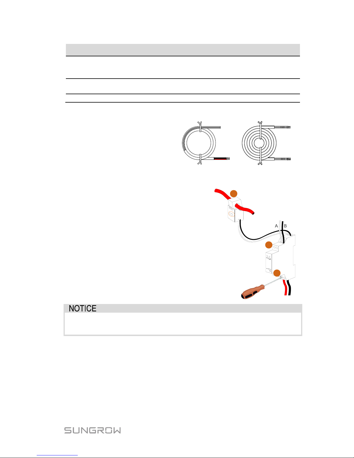
Proceed as follows to connect the cables.
1. Take out the meter (with
1-phase sensor) and the
cables from the
packaging.
L
N
B
A
B2
A
2
Power supply cable RS485 cable
2. Connect the cables to the meter.
(a) Tighten the power supply wires to
terminal 3 (L) and terminal 6 (N).
(b) Tighten the RS485-A
wire to
terminal 2 and the RS485-B wire to
terminal 5.
(c) Place the 1-phase sensor around
the phase wire (L
) from the main
switch.
The CT clamp of 1-phase sensor can
be placed before or after the main
switch.
N
Grid
Load
L
c
a
b
Make sure that the 1-phase sensor is installed in t he right dir ection : the
arrow on the sensor must point away from the grid towards the load.
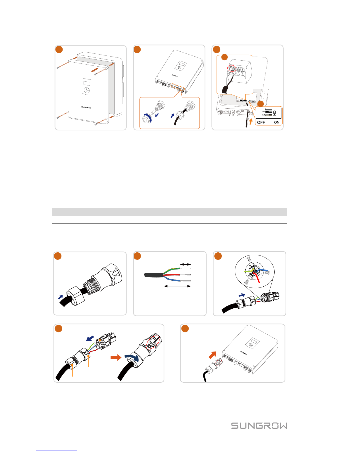
2.2.3 For Inverter Side
When the length of RS485 cable is longer than 100 m, push the 120ohM (2)
switch to “ON” to ensure stable communication
Plug the wires into the corresponding terminals on the inverter without tool
tightening.
Page 20
2 Electrical Connection Quick User Manual
10
1
2
3
A
2
B2
485
a
b
Note:
For reconnection, press the part as shown in the red circle so as to pull out the
cable.
2.3 Grid Connection
Install an A C cir cuit br eaker next to the AC output of the inverter.
Inverter Type
Specification for AC Circuit Breaker
SH3K6
20 A
SH4K6
32 A
Make sure to disconnect the AC circuit breaker and secure it against
reconnection before cable connection.
PE
L
N
8 mm
–
15 mm
40 mm
• Cross -section : 4 mm ²
• Cable diameter : 11 mm 14 mm
1
2
4
3
–
N
N
PE
PE
5
(1.2 N.m)
“Click”
“Click”
Cable gland
Housing
Terminal block
Page 21
Quick User Manual 2 Electrical Connection
11
2.4 PV Connection
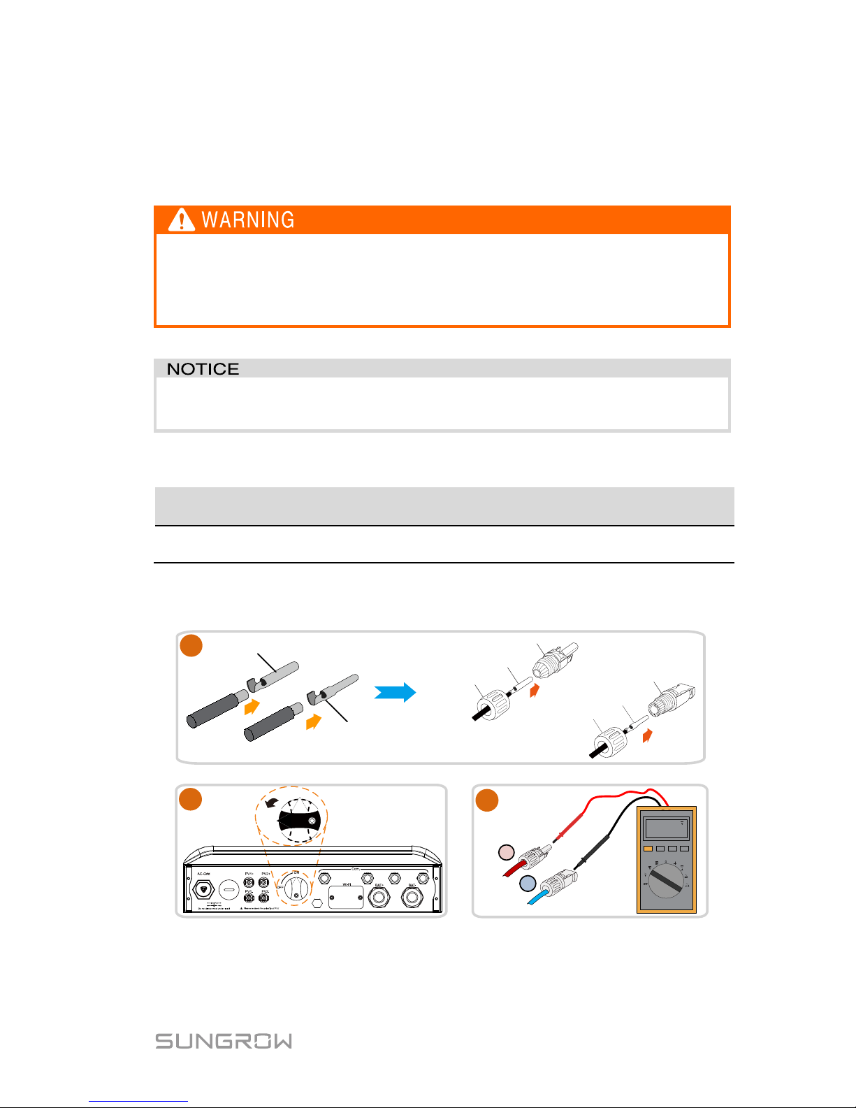
The inverter has two PV inputs and can be configured in independent mode or
parallel mode. Refer to the user manual for mode selection.
Before connecting the PV arrays to the inverter, ensure that the
impedances between the positive terminals of the PV string and Earth,
and between the negativ e terminal of the PV string and Earth are larger
than 200 kOhm.
The inverter will not function properly if the DC polarities are reversed.
Check the positive and negative polarities of the PV cells.
Cable Requirements
Cross-Section
Cable
Diameter
Max. Withstand
Voltage
Max. Withstand
Current
4 mm2–6 mm
2
AWG12–AWG10
6 mm–9 mm 600 V
Same as
short-circuit current
Strip the insulation from the cables by 7 mm–8 mm.
Tighten the cable gland with t orque of 2.5 Nm–3.0 Nm.
Positive crimp contact
Negative crimp contact
Crimp contact
Positive insulator
Cable gland
Negative insulator
Crimp contact
Cable gland
1
480.0
+
-
3
2
ON
OFF
Backup Ctrl
Page 22

2 Electrical Connection Quick User Manual
12
(Optional) Only for parallel mode.
4
5
2.5 Communication Connection
2.5.1 Ethernet Connection
Connect the inverter to the PC through the Ethernet port to set up the Ethernet
communication. The Ethernet connection with a router is shown in the following
figure.
Router/Switch
Inverter
Internet
SolarInfo Moni APP
Local access
Remote
SolarInfo Bank server
SolarInfo Bank
Webserver Explorer
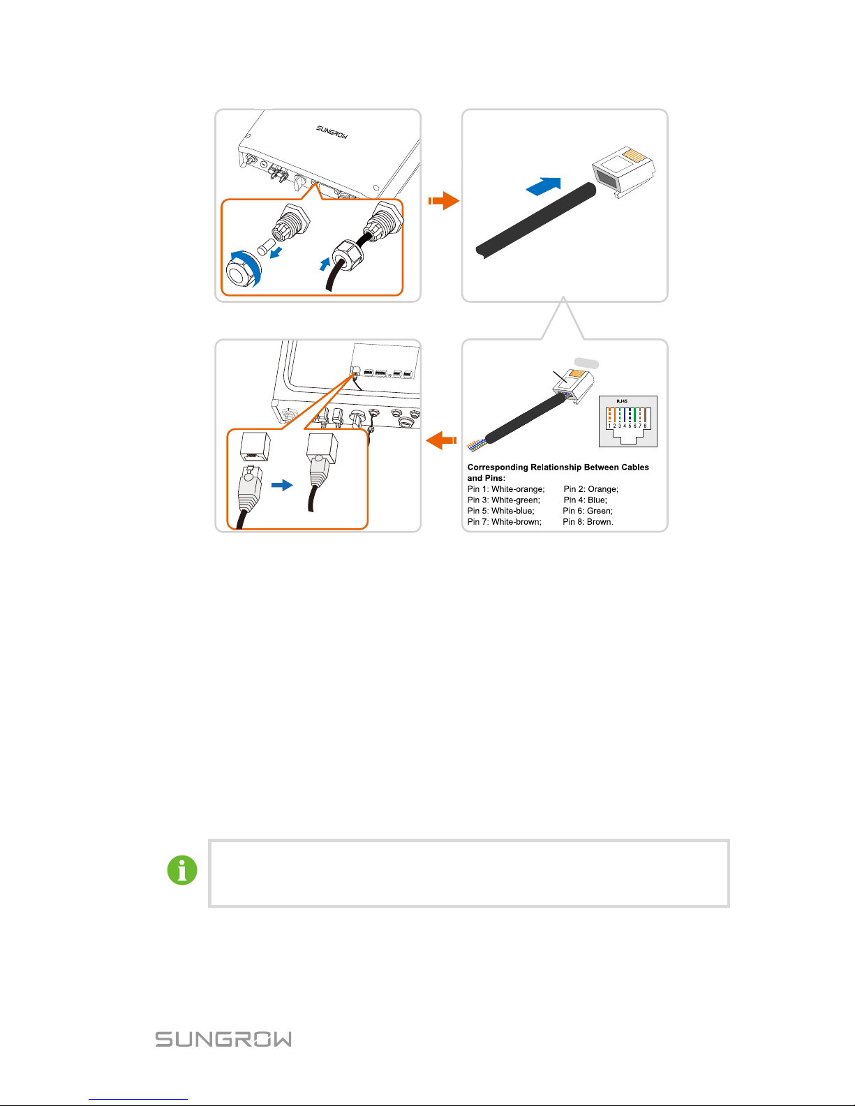
Use a TIA/EIA 568B standard network cable with a diameter of 3 mm–5.3 mm.
Remove the cable jacket by 8 mm–15 mm, and use the Ethernet crimper to
crimp the cable.
Page 23
Quick User Manual 2 Electrical Connection
13
RJ45 plug
port
1----
8
Refer to “4 SolarInfo Moni App Configuration” to use SolarInfo Moin App to
view the inverter information.
2.5.2 Wi-Fi Connection
1. Unscrew the waterproof lid from the Wi-Fi terminal.
2. Install the Wi-Fi module. Slightly shake it by hand to determine w hether it
is installed firmly.
3. Refer to the Quick User Manual delivered with the Wi-Fi module to
configure the Wi-Fi.
2.6 Battery Connection
For the connections on the battery side, see the manuals supp lie d by
the battery manufacturer.
Page 24
2 Electrical Connection Quick User Manual
14
2.6.1 Connecting the Power Cable
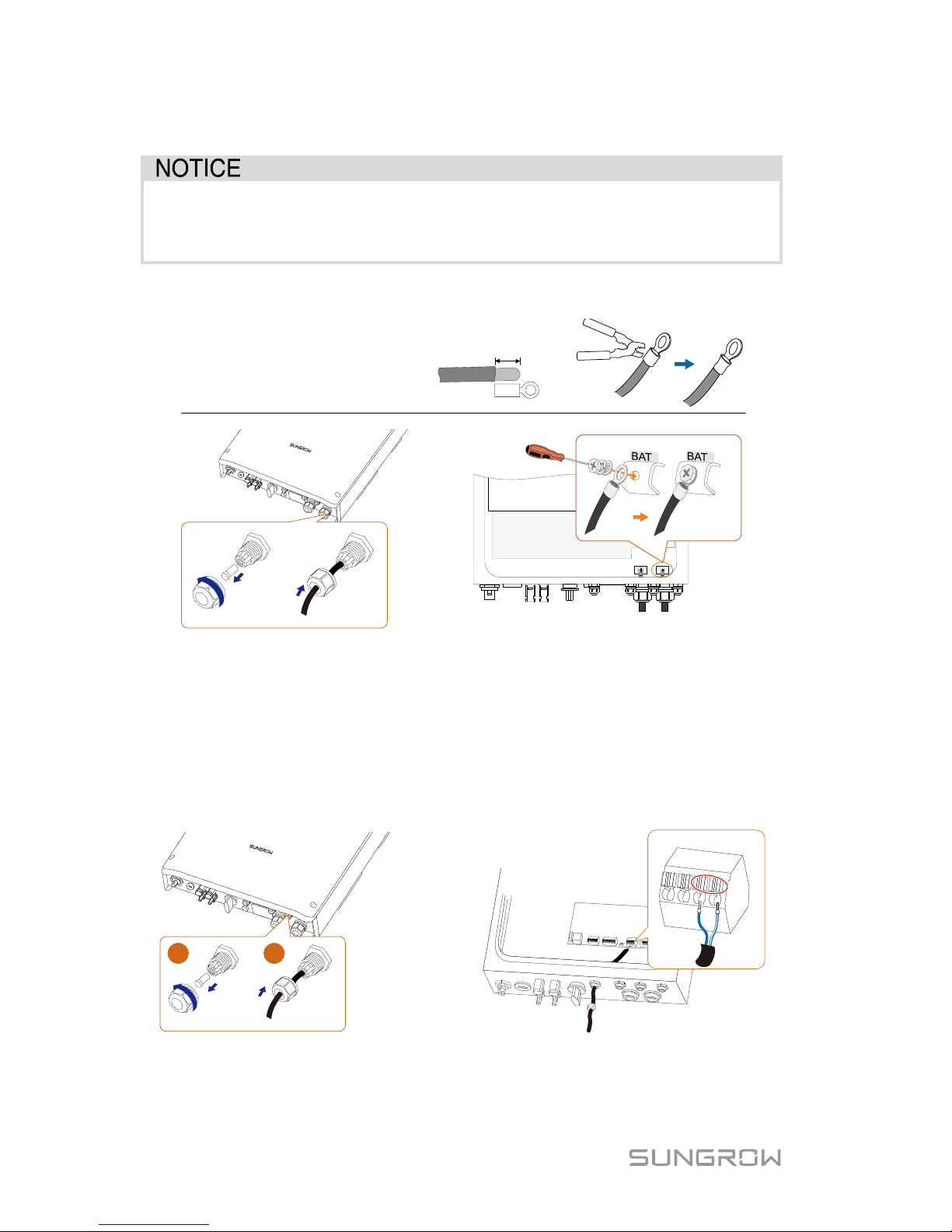
A two-pole DC circuit breaker with over-current protection (voltage
rating not less than 100 V and current rating not less than
100 A)
should be installed between the inverter and the battery module.
Be sure to adhere to the following screw assembly sequence: screw head,
spring washer, fender washer, OT terminal.
15
mm
Cross-section: 16 mm
2
–
25 mm2,
Cable diameter: 13 mm
–
16 mm
OT25-6
Torque 2.5 N m
-
-
2.6.2 Connecting the CAN Cable
The CAN cable enables communication between the inverter and the Li-ion
battery from LG, GCL, Pylon (US2000B), BYD or Sungrow.
Take out the CAN cable from the packaging. Lead the cable through the cable
gland and plug the wires into the corresponding terminals without tool
tightening.
1
2
CANH
CANL
BAT_Com
.
Note: For reconnection, press the part as shown in the red circle so as to pull
out the cable.
Page 25
Quick User Manual 2 Electrical Connection
15
For GCL and BYD batteries, if there are fou r wires, please cut through
the green (pin 6) and white-green (pin 3
) wires from the CANH and
CANL terminals to set up successful communication.
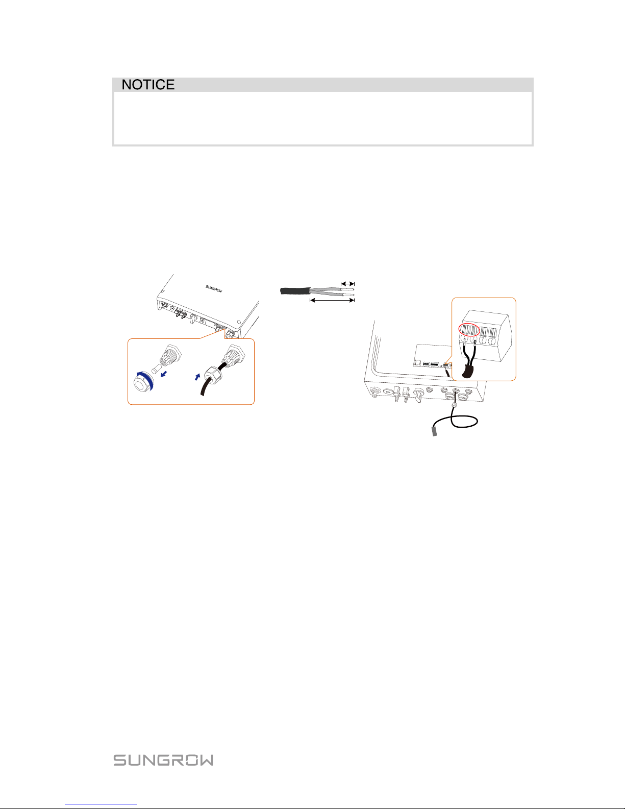
2.6.3 Connecting the Temperature Sensor
It is recommended that the PT1000 is connected to the inverter to sample the
temperature of the lead-acid battery or the external environment of the battery.
The temperature sensor is located next to the lead-acid battery.
Cross-section: 1.0 mm², cable diameter: 3 mm–5.3 mm
PT1000
5 mm -7 mm
40 mm -50 mm
BAT_Temp.
Note:
For reconnection, press the part as shown in the red circle so as to pull out the
cable.
2.7 DO Connection
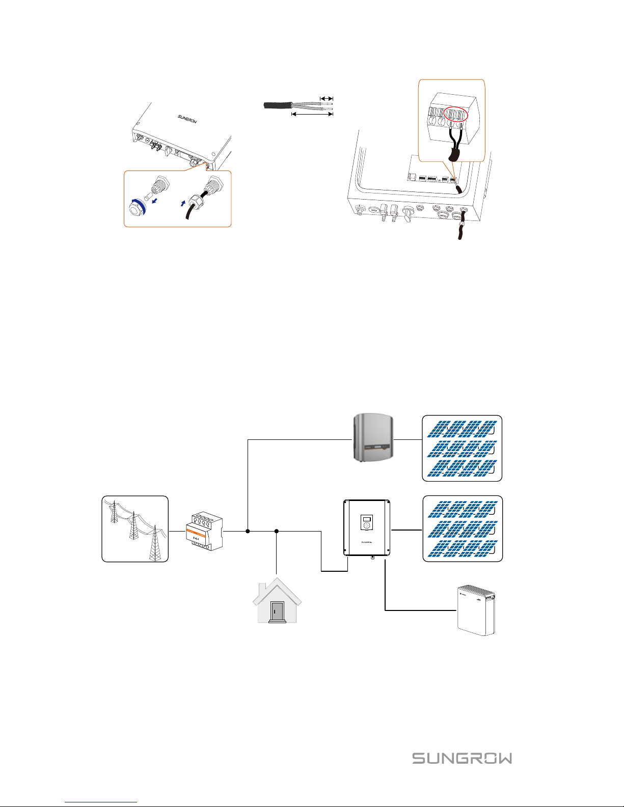
The inverter has two DO relays with different functions as follows:
DO1: Consumer load control. Please choose the appropriate contactor
according to the load power, e.g., the contactor types of the 3TF30 series
from SIEMENS (3TF30 01-0X). The relay is activated once the conditions of
the control mode are satisfied.
DO2: Earth fault alarm. Once the inverter receives the earth fault signal, the
relay closes the contact. The relay remains triggered until the fault is
removed.
Cross-section: 1.0 mm², cable diameter: 3 mm–5.3 mm
Page 26
2 Electrical Connection Quick User Manual
16
5 mm 8mm
40 mm 50mm
–
–
–
DO1
COM1
NO1
DO2
COM2 NO2
Note:
For reconnection, press the part as shown in the red circle so as to pull out the
cable.
2.8 Retrofitting the Existing PV System
The hybrid inverter is compatible with any single-phase PV grid-connected
inverters. An existing PV system can be retrofitted to be a PV Energy Storage
System with the addition of SH3K6 / SH4K6.
Home appliance
SH3K6/
SH4K6
AC
PV inverter
Fig. 2-3 Retrofitting the Existing PV System
The power generation from the existing PV inverter w ill be firstly provided to the
loads and then charge the battery. With the energy management function of the
hybrid inverter, the self-consumption of the new system will be greatly
improved.
Page 27
Quick User Manual 2 Electrical Connection
17
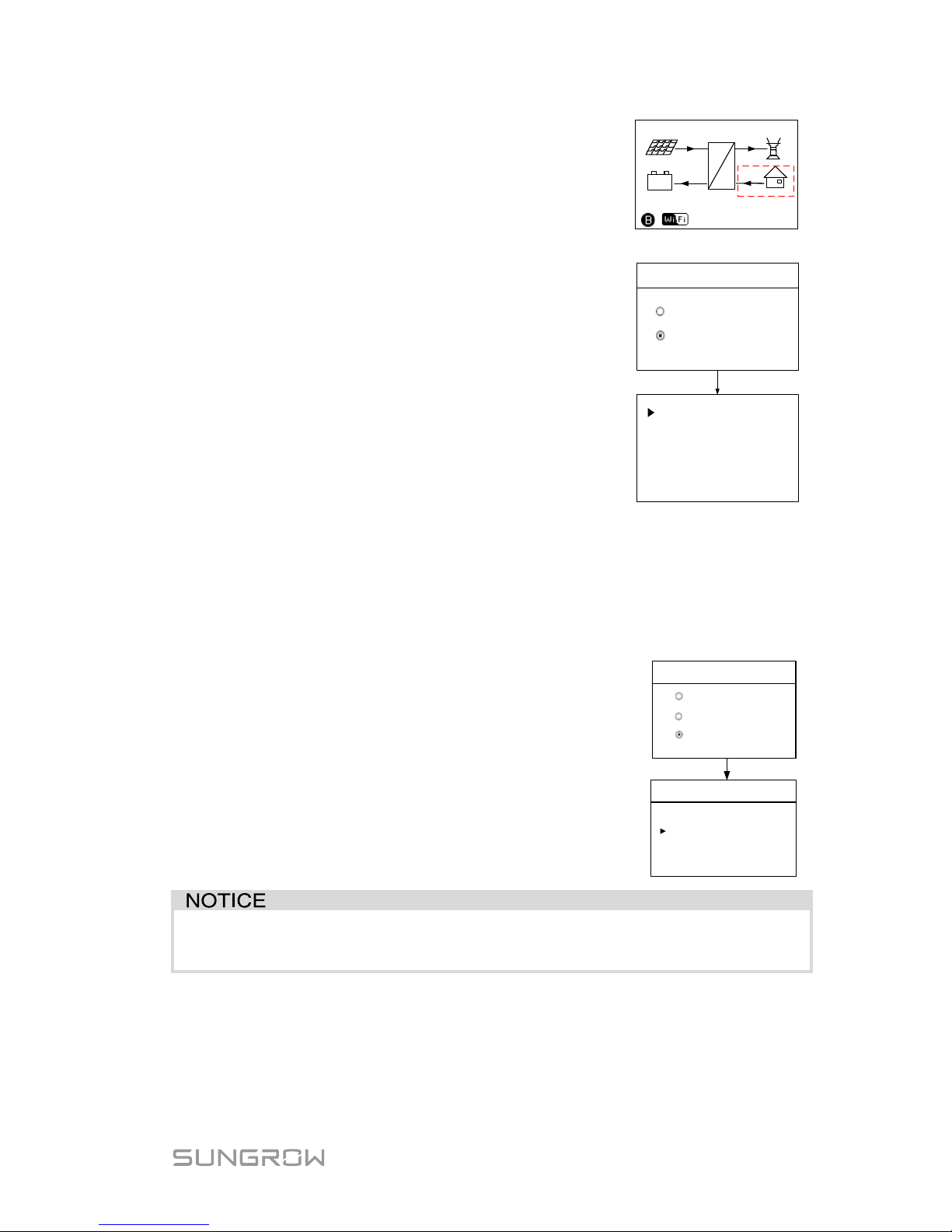
The existing PV inverter works as a load in the
whole system but supply PV power to the energy
storage system, as the power flow shown on the
main screen.
4600
Running
=
~
3000
2200
600
16:37
(W)
+
-
*
Existing Sys Rated-P: the rated power of the existing
PV system.
Total Export Limit: the export power limit of the new
system
The lower limit is the rated power of the existing
PV system.
The upper limit is ([rated power of the hybrid
inverter] + [rated power of the existing PV
system]).
For example, retrofit an existing PV system (rated
power: 3000 W) with the hybrid inverter SH4K6 (rated
power: 4600 W). The total export limi t can be set from
3000 W to 7600 W.
Existing Sys
Enable
Disable
Existing Sys Rated-P
00000W
Total Export Limit
04600W
The export power limit can also be set via the zero-export in commissioning.
Proceed as follows to perform the settings.
According to the local regulations in Germany, please
set the export power to 70 %
of the installation
capacity.
For example, with a total maximum installation capacity
of 4600 W (SH4 K6), the export power should be set to
3220 W (i.e. 4600 * 70 %).
Partial
2/
2
Zero
-export
ON
OFF
Partial
1/
2
Export Pwr[
W] 4600
The settings in the two submenus are from the same source. If one is
changed, the other will synchronize the value.
2.9 Connecting to Interface Device for SPI (Italy)
The inverter has integrated the interface protection system (SPI) to provide the
following functions:
Page 28
2 Electrical Connection Quick User Manual
18
Maximum/minimum frequency protection;
Ability to receive signals aimed at changing the frequency protection
thresholds and to receive the command of remote shutdown.
2
1
3
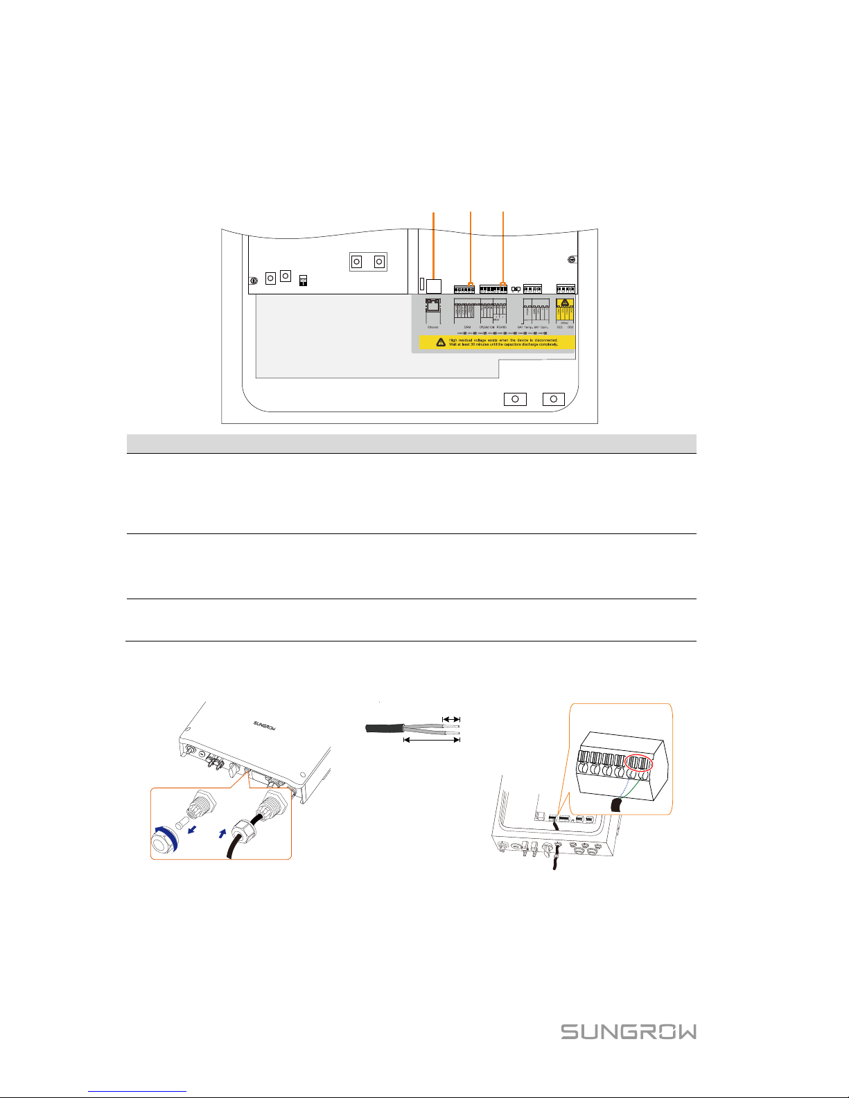
NO.
Interface
SPI Function
1 Ethernet
Remote control. Receive external signal/command to
change the frequency protection parameters or shutdown
the inverter. See “
2.5.1 Ethernet Connection
“ for the
cable connection.
2
RefGen,
Com/DRM0
Local control. Shortly connecting the two terminals will
change the frequency protection parameters.
See Fig.
2-3
.
3 A1, B1
Receive external command to shutdown the inverter
remotely. See
Fig. 2-4
.
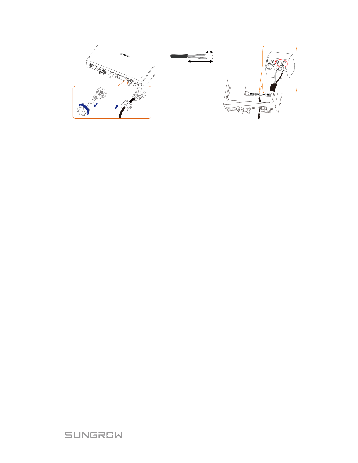
The following figure shows the cable connection to external interface device.
Cross-section: 2*0.5 mm², cable diameter: 3 mm–5.3 mm
5 mm
–
7mm
40 mm
–
50 mm
DRM
RefGen
Com/DRM0
Fig. 2-4 RefGen and Com/DRM0 Connection
Page 29
Quick User Manual 2 Electrical Connection
19
5 mm
–
7mm
40 mm–50 mm
A1
B1
485
Fig. 2-5 RS485 Connection to External Device
Note:
For reconnection, press the part as shown in the red circle so as to pull out the
cable.
Page 30
20
3 Commissioning
3.1 Button Function
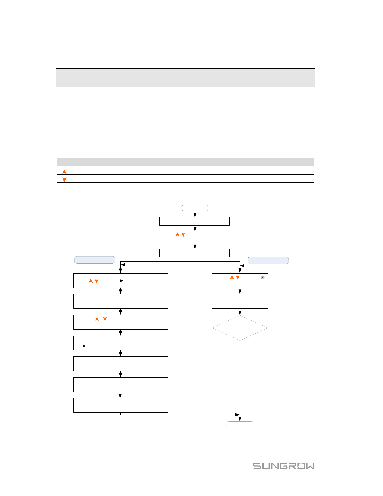
The inverter offers four buttons for operation. Please refer to the following table
before any operation of the inverter.
Tab. 3-1 Button Function
Button
Description
For navigating up or increasing the setting value.
For navigating down or decreasing the setting value.
ESC
For navigating to the left, quitting the menu or canceling the settings.
ENT
For navigating to the right or confirming a selection or settings.
Selecting mode
Modifying mode
Press / to move to the desired item.
Press ENT and the first digit of the
value to be set flashes.
Press / to set the value and
Press ENT/ESC to move the cursor.
Press ENT if the whole value is OK and
the will move back to the item name.
Repeat the steps above for the
settings of the other items.
Press ESC to quit the menu and a
prompt will appear.
Press ENT to save and apply the setting.
To discard the setting, Press ESC.
Press ENT to enter the menu.
Press / to navigate through
the menu.
Press ENT to confirm a selection.
Press / to move
to the desired item.
Press ENT to confirm.
Sub-parameters
to be set?
End
Start
No
Yes
(modifying)
Yes
(selecting)
Fig. 3-1 Button Operations
Page 31
Quick User Manual 3 Commissioning
21
3.2 Commissioning Procedure
Before starting the inverter, make sure all the installation and connections are
completed and verified. Proceed as follows to start the inverter for the first time.
1. Connect the AC circuit breaker.
2. Connect the DC circuit breaker between the inverter and the battery
pack.
3. (Optional) Power on the battery pack manually if a battery is equipped.
4. Rotate the DC switch to “ON”. The DC switch may be integrated in the
inverter or installed by the customer.
5. The LCD screen will be activated 5s later and enter the initial settings.
Initial Settings
1/3
Time
Country
Initial Settings
2/3
Zero-export
Reactive Power
Initial Settings
3/3
Exit
Earth Fault
Battery Usage Time
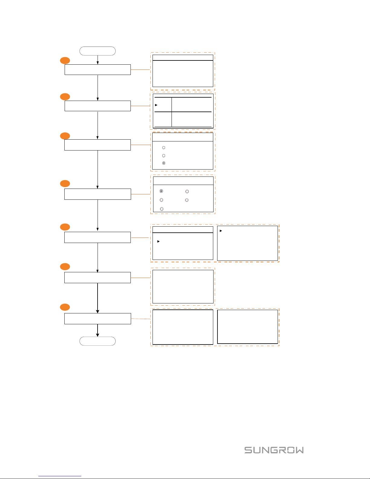
6. Refer to Fig. 3-1 for button operations and complete all initial settings
according to the procedure in Fig. 3-2.
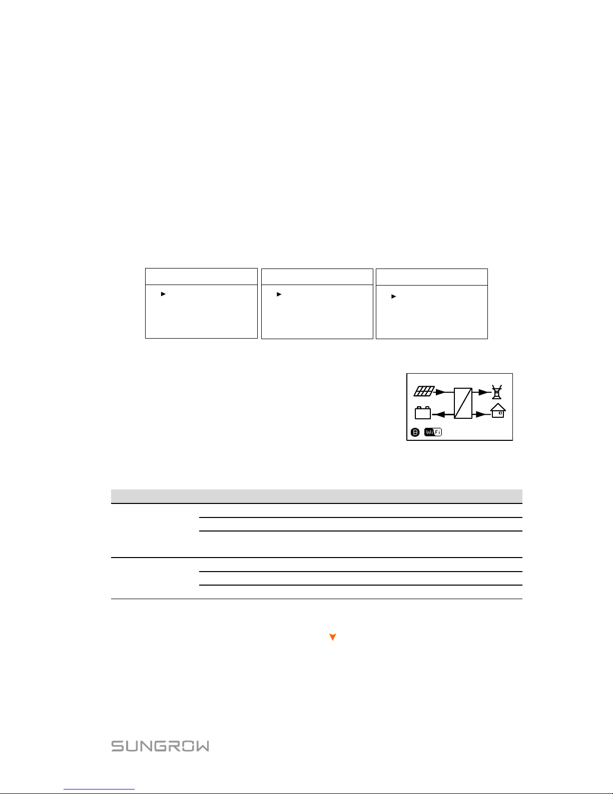
7. Check the icons on the main screen. Refer to
Tab. 5-1 for the explanations.
4600
Running
=
~
2000
2000
600
16:37
(W)
+
-
8. Check the status of the indicator.
Tab. 3-2 Status Descriptions of the Indicator
Colour
Status
Description
Green
On
The inverter is running normally.
Blinking
The inverter is in the process of starting.
Off
Other statuses except Running and Startup.
(Refer to Tab. 5-1 for status descriptions.)
Red
On
Permanent fault or upgrade failure.
Blinking
Other system faults or main alarms.
Off
No fault occurs.
9. Visit www.solarinfobank.com or SolarInfo Moni APP to view inverter
information. Get the related manuals at www.sungrowpower.com.
If the inverter commissioning fails, Press
to view the current errors. Remove
the existing malfunctions and then repeat starting up the inverter according to
the procedure detailed in this section.
Page 32
3 Commissioning Quick User Manual
22
Set the time
Set the country code
1
2
4
3
5
6
7
Set zero-export
Test earth fault alarm
Date
Time
22 / 02 / 15
07 : 38 : 08
hh : mm : ss
DD / MM / YY
Testing earth fault
relay and buzzer
inside alarm . . .
End
Start
Zero-export
ON
OFF
Partial
1/2
Confirm Exit?
Incorrect configura-
tion may cause a
fault!
Complete initial settings and
exit
Set the reactive power
Set battery usage time
Weekend Usage
Weekday Usage
Bat Usage Time
Start Time1
End Time1
00:00
24:00
Start Time2
End Time2
00:00
24:00
(1) The time setting is very important,
which directly affects data logging.
(2) DD, MM, and YY stand for day,
month, and year respectively.
(3) hh, mm, and ss stand for hour,
minute, and second respectively.
ON: no power will be exported to grid.
OFF: all output power will be exported
to grid.
Partial: you can set the export power.
* Automatically return to main menu
after 3s.
Initializing...
Reactive Power
PF
OFF
Q(u)
Q(p)
Qt
Country
Country:
[ GB ]
OFF: Disable the function
PF: Fixed power factor mode
Q(t): Fixed reactive power mode
Q(p): Characteristic PF curve for
power response mode
Q(u): Volt-var response mode
Fig. 3-2 Initial Settings
Page 33
Quick User Manual 3 Commissioning
23
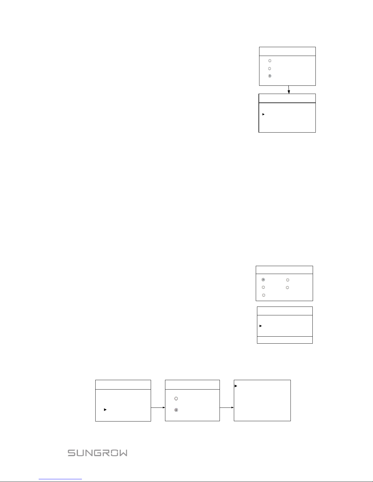
Zero-export (Partial):
ON: no power will be exported to the grid.
OFF: all i nverter output power will be exported to the
grid.
Partial: set partial of the output power to export to
the grid.
According to the local regulations in Germany,
please set the export power to 70 %
of the
installation capacity.
Partial
2
/2
Zero-export
ON
OFF
Partial
1/2
Export Pwr[W] 4600
For example, with a total maximum installation capacity of 4600 W (SH4K6), the
export power should be set to 3220 W (i.e. 4600 * 70 %).
Export power range:
When the existing system is disabled, the range is from 0 to the rated
power of the hybrid inverter.
When the existing system is enabled,
− the lower limit is the rated power of the existing PV system.
− the upper limit is ([rated power of the hybrid inverter] + [rated power of
the existing PV system]).
− the value will synchronize with the settings for retrofitting an existing
system.
Reactive power regulation:
OFF:
The reactive power regulation function is disabled.
The power factor (PF) is limited to +1.000.
“PF” mode:
The inverter is capable of operating with fixed power
factor.
The PF ranges from 0.8 leading to 0.8 lagging.
Leading: the inverter is sourcing reactive power to the
grid.
Lagging: the inverter is sinking reac tive power from the
grid.
For the explanations of other modes, see the User
Manual in the CD.
Reactive Power
PF
OFF
Q(u)
Q(p)
Qt
PF Setting
PF + 1.000
+ : Laggingg & - : Leading
Battery usage enabled (Weekend):
Bat Usage Time
Weekday Usage
Weekend Usage
Weekend Usage
Disable
Enable
Start Time 1
End Time 1
00:00
24:00
Start Time 2
End Time 2
00:00
24:00
Press
ENT
Press
ENT
Page 34

3 Commissioning Quick User Manual
24
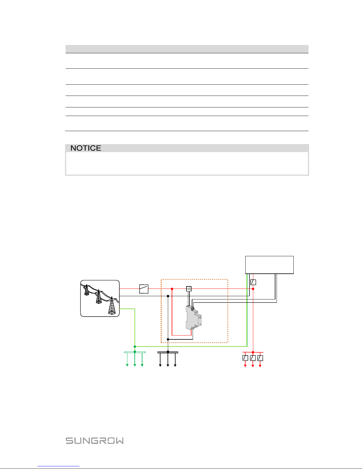
(Optional) For lead-acid batteries, you should manually set the battery type.
− Turn of f t he inverter via the LCD m enu.
5000
Running
=
~
3000
100
1900
16:
37
(W
)
+
-
Menu
ON
/
OFF
Settings
Run Info
1/
5
ON / OFF
OFF
ON
Confirm ‘OFF’?
− Set the battery type to “Other Battery”.
0
Turn off
=
~
0
500
500
16:37
(W)
+
-
Menu
ON / OFF
Settings
Run Info
1/5
Password:
1 1 1
Settings
2/5
Settings
Bat Usage Time
Forced Charge
Battery Type
− Press / to select “Other
Battery” and Press ENT to
confirm.
Battery Type
Other Battery
1/1
Press
ENT
No Battery
Li-ion
Only qualified personnel are allowed to
adjust relevant parameters. Improper settings may cause damage
to the inverter!
Max. Chrg / Max. DChrg:
Make sure that the charge or discharge current is not
beyond the upper limit (65 A) to protect the battery from
overcharging or deep discharging.
The unit C is the “capacity”, which refers to the maximum
amount of charge that a battery can store. If the max
charge or discharge is set to more than 65 A (e.g. C = 600
Ah, 0.3 C = 180 A), then the inverter will limi t the charge
and discharge current to 65 A.
Rated Vtg
Capacity
048.0 V
0200 Ah
Max. Chrg
Max. DChrg
0.300 C
0.300 C
If the battery voltage or temperature is beyond the
allowable range, the related error codes will be triggered
and the protection function will
be activated to stop
charging or discharging.
Over Vtg
Low Vtg
58.8 V
42.0 V
Over Temp
Low Temp
60.0 ℃
-25.0 ℃
DChrgEndVtg:
Stop discharging at a voltage not lower than DChrgEndVtg,
so as to protect the battery from deep discharging.
The DChrgEndVtg setting value should be higher than the
Low Vtg setting value.
CSTVtgChrg
DChrgEndVtg
56.40 V
43
.20
V
Tab. 3-3 Description of Other Lead-acid Battery Parameter
Parameter
Description
Range
Max. Chrg
The upper limit of the charging current
0.05C to 2C
Max. DChrg
The upper limit of the discharging current
0.1C to 2C
Rate Vtg
The rated voltage of the equipped battery
30 V to 60 V
Capacity
Capacity of the battery tray
10 Ah to1000 Ah
Page 35
Quick User Manual 3 Commissioning
25
Parameter
Description
Range
Over Vtg
The upper limit of battery voltage when
charging
48 V to 70 V
Low Vtg
The lower limit of battery voltage when
discharging
32 V to 48 V
Over Temp The upper limit of battery temperature
20℃ to 70℃
Low Temp The lower limit of battery temperature
-30℃ to 10℃
CSTVtgChar
The voltage of constant-voltage charging.
40 V to 63 V
DChrgEndVtg
The voltage at which the discharging is
stopped
30 V to 53 V
* Consult battery manufacturer for an advice before any modification.
In the case of commissioning failure, power off the system and wait 1
minute to commission the syst em agai n.
3.3 Result Verification
3.3.1 Meter Installation and Connection
For the single-phase meter, with the signal from the 1-phase sensor, the
inverter determines the energy exchange with the utility grid on one phase. The
CT clamp of 1-phase sensor can be placed before or after the main switch.
L
A
B
L
N
N
PE
PE bar
Neutral bar
Main Switch
SUNGROW
Meter
Utility Grid
Inverter
Solar
switch
Home appliance
1-phase sensor
Fig. 3-3 Correct Installation and Connection of the Single-phase Meter
The following figure shows the correct installation and connection of the
three-phase meter.
Page 36

3 Commissioning Quick User Manual
26
SUNGROW
Meter
L3
N
PE
PE bar Neutral bar
Home appliance
Main Switch
AC circuit breaker
Utility Grid
L1
L2
IN
OUT
A
B
Load side
Grid side
Inverter
Fig. 3-4 Correct Installation and Connection of the Three-phase Meter
Before the verification, disconnect the DC switch between the inverter and the
battery module.
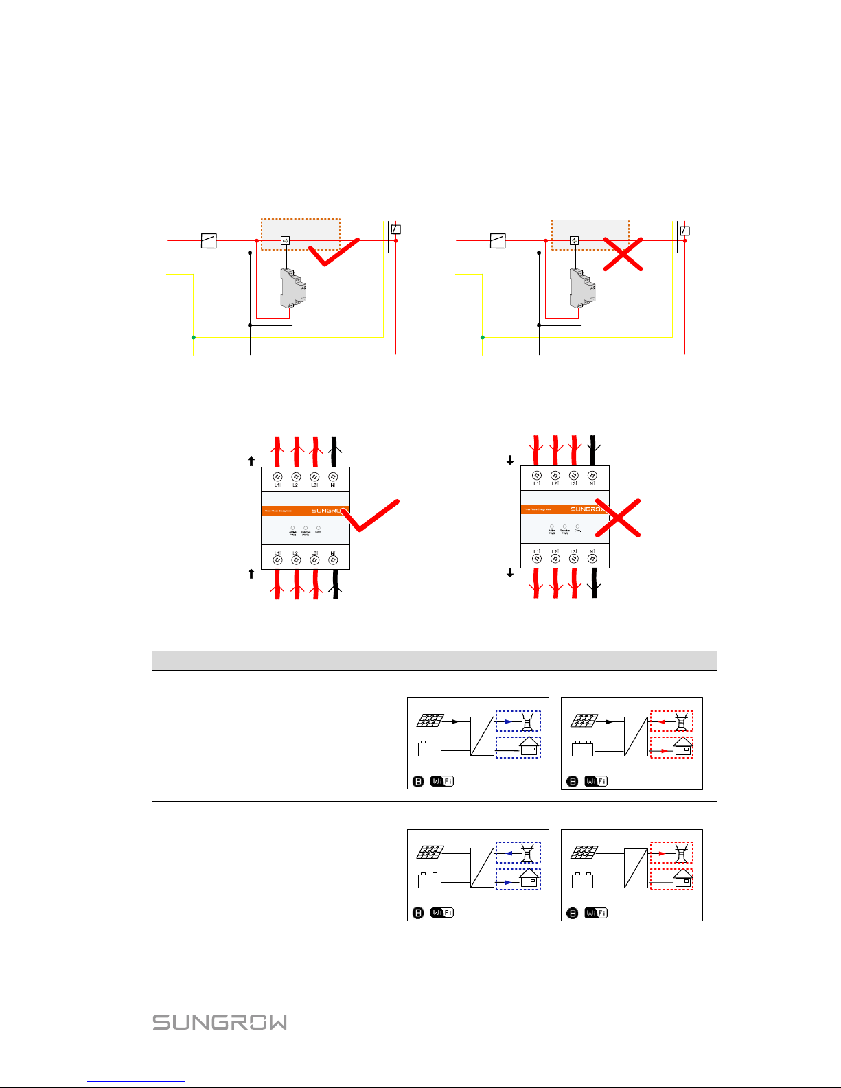
For Incorrect Installation Position
Make sure that the 1-phase sensor of the SUNGROW meter should be placed
to the phase line (L) from the main switch. If otherwise, the energy flow
indicated on the LCD will be wrong.
L
L
N
N
PE
PE bar
Neutral bar
Main switch
SUNGROW
Meter
1
-
phase sensor
Inverter
Home appliance
L
L
N
N
PE
PE bar
Neutral bar
SUNGROW
Meter
1-phase sensor
Inverter
Home appliance
Main switch
Action
LCD Display Explanation
Turn off all the household loads.
All the PV power generation
should be exported to the grid,
as shown in the “Correct” figure.
4000
Running
=
~
4000
16:37
(W)
+
-
4000
Running
=
~
0
16:37
(W)
+
-
Correct Wrong
0
4000 0 0
Page 37
Quick User Manual 3 Commissioning
27
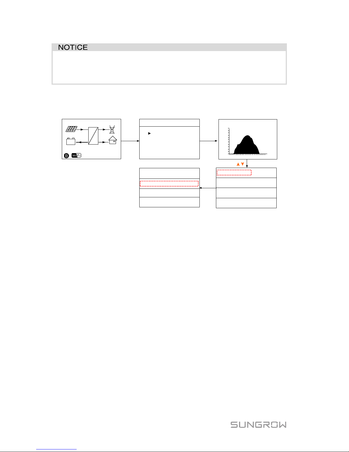
For Reverse Sensor Connection
Make sure that the arrow on the 1-phase sensor must point away from the grid
towards the load. If otherwise, the energy flow indicated on the LCD will be
wrong.
L
L
N
N
PE
PE bar
Neutral bar
Main switch
SUNGROW
Meter
1
-
phase sensor
Inverter
Home appliance
L
L
N
N
PE
PE bar
Neutral bar
Main switch
SUNGROW
Meter
1
-
phase sensor
Inverter
Home appliance
Fig. 3-5 Correct CT Installation for Single-phase Meter
OUT
IN
Load side
Grid side
OUT
IN
Load side
Grid side
Fig. 3-6 Correct Power cable connection for Three-phase Meter
Action
LCD Display Explanation
Method 1:
Turn off all the household loads.
All t
he PV power generation
should be exported to the grid,
as shown in the “Correct” figure.
4000
Running
=
~
4000
16:37
(W)
+
-
4000
Running
=
~
4000
16:37
(W)
+
-
Correct Reverse
0
8000 0
0
Method 2:
Stop the inverter via the LCD
menu and turn o n the household
loads.
All the load power consumption
should be imported from the grid,
as shown in the “Correct” figure.
0
Turn off
=
~
4000
16:37
(W)
+
-
0
Turn off
=
~
4000
16:37
(W)
+
-
Correct Reverse
4000
0
0 0
Page 38
3 Commissioning Quick User Manual
28
The reverse sensor connection will cause the comm unicat i on fault 084.
To clear the fault 084, please turn off the DC sources and then restart
the system after reconnecting the sensor in correct direction.
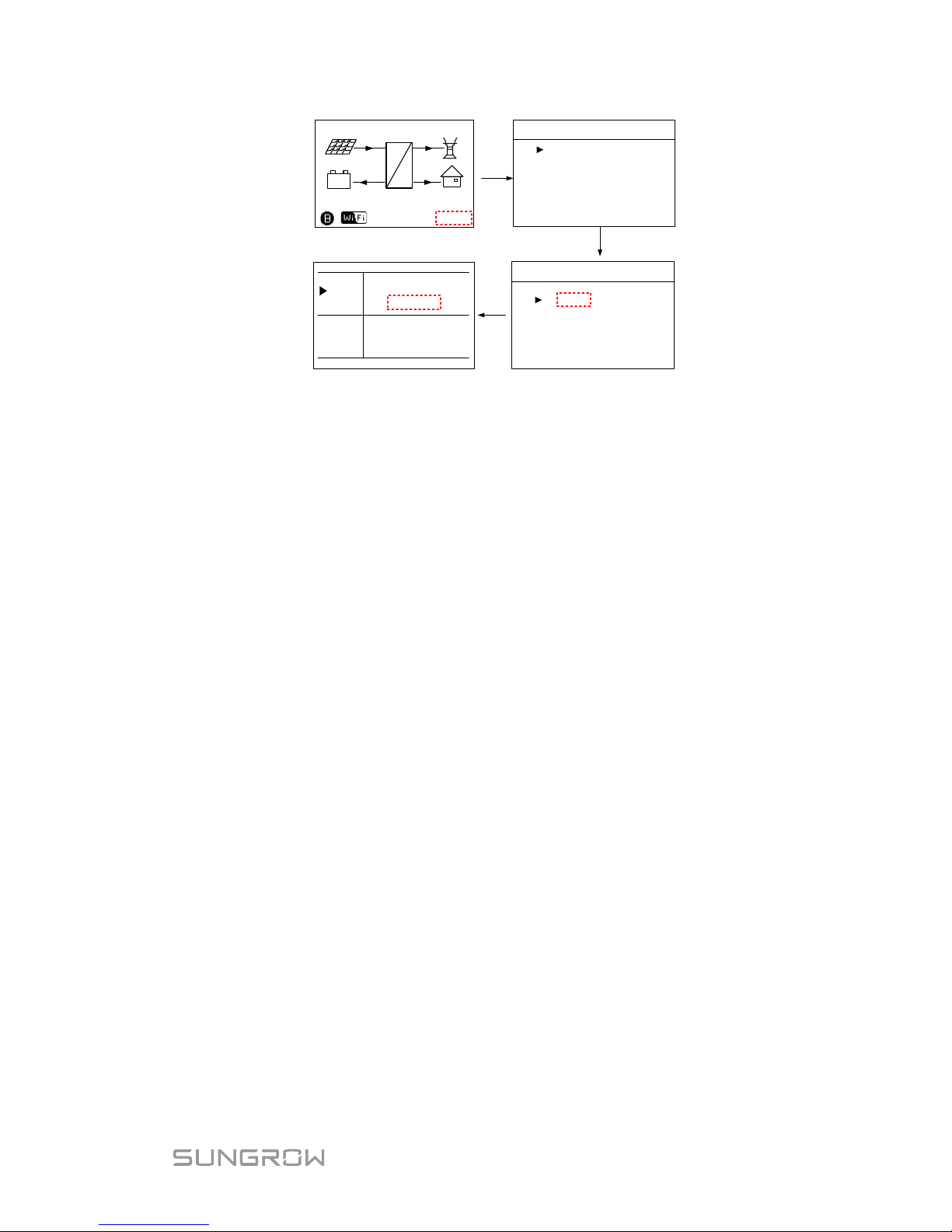
3.3.2 Battery Information
After initial settings, check the detailed battery information on the LCD display.
4600
Running
=
~
2000
2000
600
16:37
(W)
+
-
Menu
ON / OFF
Settings
Run Info
1/2
Bat Tmp
36.1°C
Li-ion Sungrow
Bat SOC 99.9%
Bat SOH
100.0%
Press
ENT
Press
ENT
t
0
6
12
18
24
P(kW)
07/17(PV)
5.0
2.5
0
Scroll pages by pressing /
Input Mode Indep.
CO2 Reduced 58kg
Bat Cap 4.8kWh
Self Csmp
89.9%
If the battery type or capacity setting is inconsistent with the actual, the
charge/discharge current may be less than the actual charge/discharge ability.
However, the system can operate normally. Proceed as follows to modify.
1. Stop the inverter via the LCD menu.
2. Reset the battery type and parameters. Proceed as follows to enter the
submenu.
3. Start the inverter via the LCD menu.
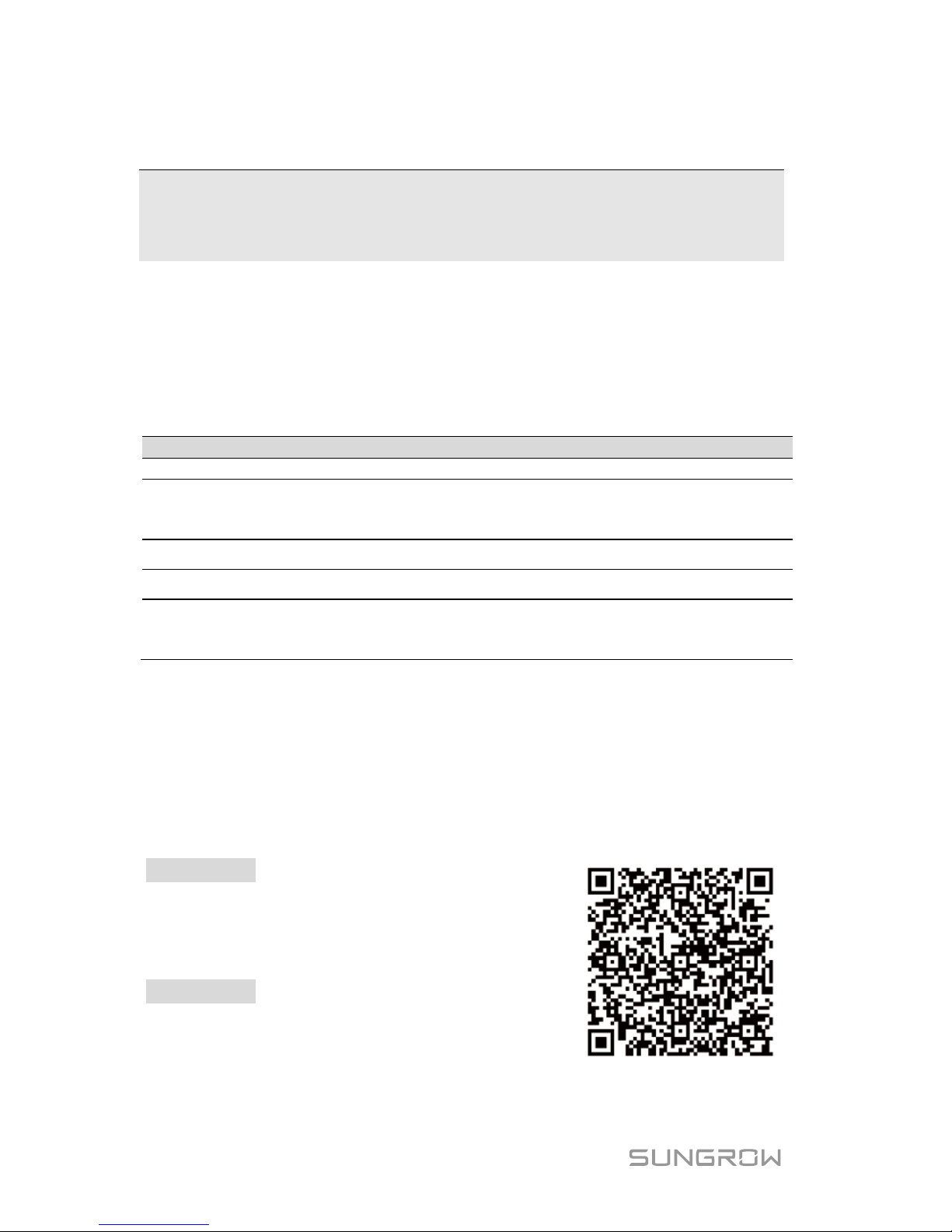
3.3.3 System Time
The correct system time is very important. If there is deviation between the
system time and the local time, the inverter will not operate normally. The clock
is in 24-hour format. Proceed as follows to set the correct time.
Page 39
Quick User Manual 3 Commissioning
29
Menu
ON / OFF
Settings
Run Info
1
/2
Date
Time
22 / 02 / 15
16 : 37 : 08
hh : mm : ss
DD / MM / YY
Menu
Time
Country
2/2
Error Record
Press
ENT
4600
Running
=
~
2000
2000
600
16:37
(W)
+
-
Page 40
30
4 SolarInfo Moni App
Configuration
If the inverter has been connected to the home router with an Ethernet cable,
the user can view inverter information via the SolarInfo Moni App.
4.1 App Operation Requirements
Item
Android System
iOS System
System version
Android 4.0 or above
iOS 7.1 or above
System resolution
1280*720, 1920*1080,
800*480, 2560*1440,
960*540
960*640, 1136*640,
1334*750, 1920*1080
System memory 512 MB
Normal Net speed Higher than 40 kB/s
Distance between phone
and WiFi module (for local
access)
Less than 150 m and no obstacles
4.2 Installing the App
Download the SolarInfo Moni App and install it into your smart phone. You can
select the App version for iOS or Android.
For iOS
Scenario 1
Download SolarInfo Moni A
pp at
https://itunes.apple.com/us/app/solarinfo-mon
i/id1048873556?l=zh&ls=1&mt=8.
Scenario 2
Use your smart phone to scan the QR code to
download and install the App.
For i
OS
Page 41

Quick User Manual 4 SolarInfo Moni App Configuration
31
Scenario 3
Search for SolarInfo Moni in your App Store to download and install it.
For Android
Scenario 1
Download SolarInfo Moni App at
http://www.solarinfobank.com/app/list.
Choose the SolarInfo Moni App for Android.
Scenario
2
Use the scanning function of the Play Store or
Explorer in your smart phone to scan the QR
code to download and install the App.
For Android
4.3 Visiting in “Local Access” Mode
Do not name your router started with "SG-". Otherwise you cannot find
it. The SN and password are displayed on the inverter nameplate.
Proceed as follows to use the SolarInfo Moni App in "[Local Access]" mode.
1. Enable the Wi-Fi function of your smart phone and connect it to the home
router.
Change Off to On
Select your WiFi network
1
2
Enter router’s password
TP-LINK_67F
23E
TP
-
LINK_67F23E
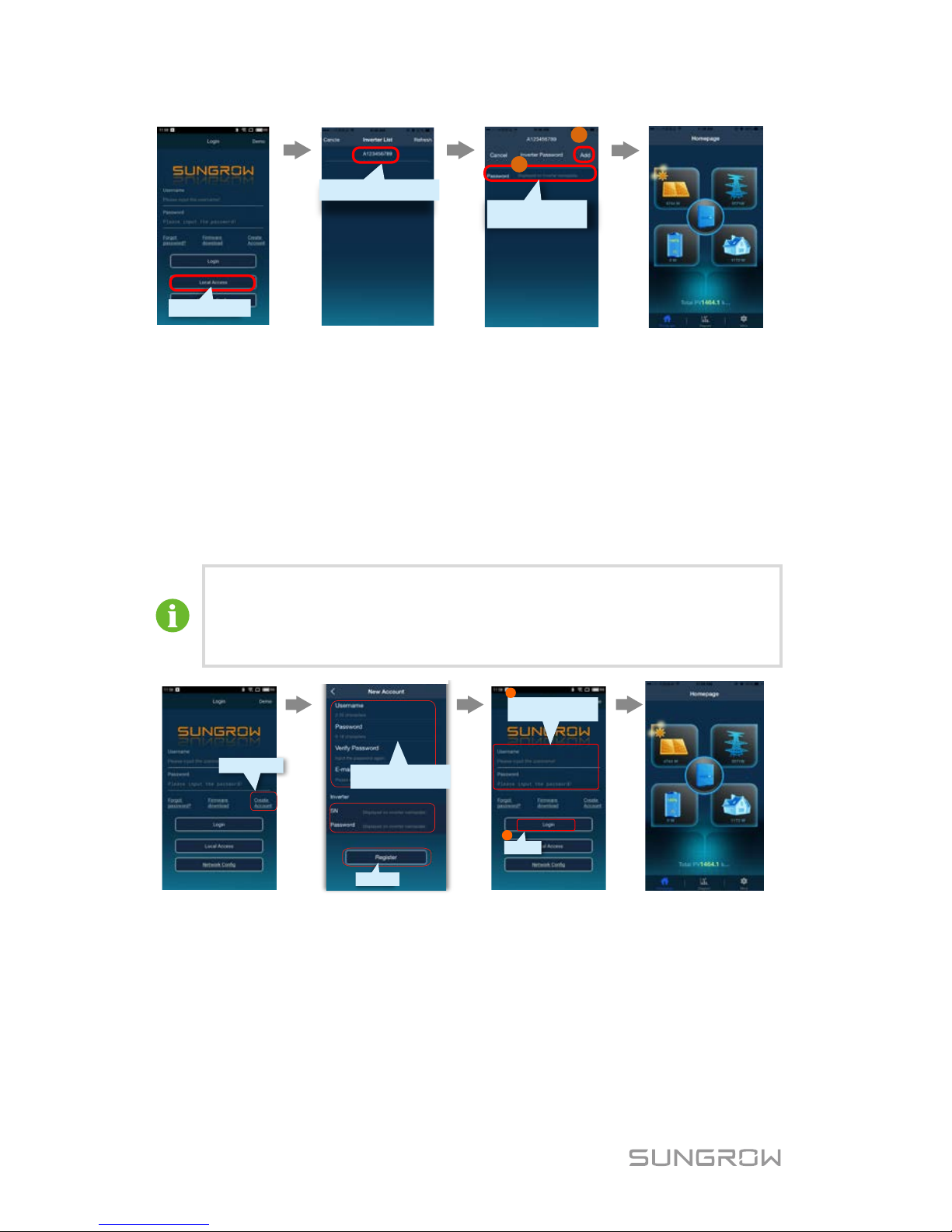
2. Visit the App in “Local Access” mode, select you inverter SN and input
the password, then you can view the inverter information.
Page 42
4 SolarInfo Moni App Configuration Quick User Manual
32
Click the inverter
SN
1
2
Local Access
Input the inverter
password
4.4 Visiting in "[Login]" Mode
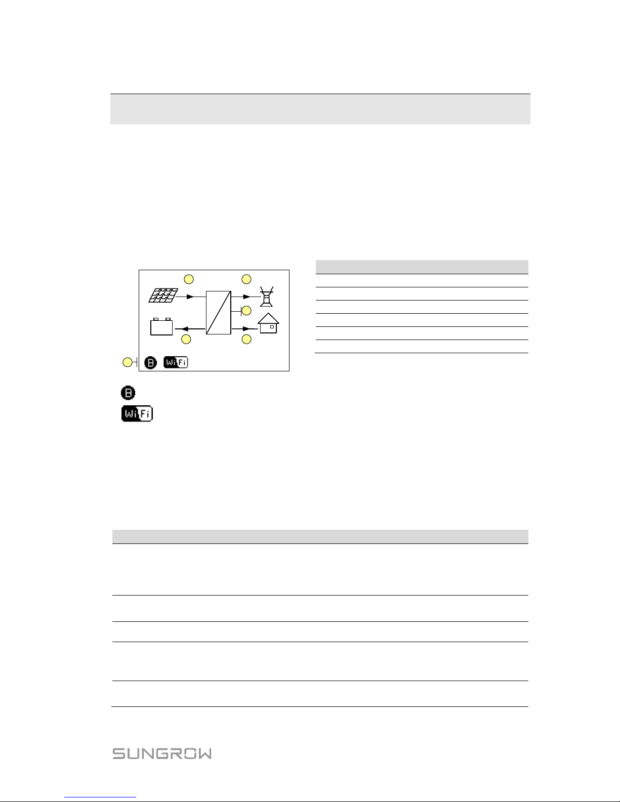
Connect the inverter to your home router and complete the App registration.
Then you can visit SolarInfo Moni App in "[Login]" mode and view the
information wherever you happen to carry the smart phone. To perform the
operations in this section, be sure that your smart phone can access the
Internet.
The e-mail address will be used to receive relevant mails, so it
must be valid.
The username will be needed when you find the forgotten
password. If you forget the username, re-register.
Register
Create Account
1
Login
2
Input your account
and password
Username, password and
E-mail
Page 43
33
5 LCD Operation
Refer to Tab. 3-1 Button Function for the operation instruct i ons.
5.1 Main Screen
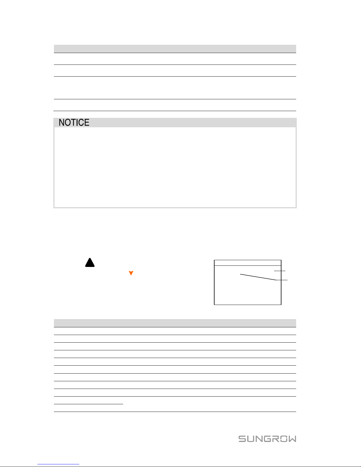
If the inverter succeeds in commissioning, the LCD screen will enter the main
screen.
6
4600
Running
=
~
2000
2000
600
16:37
(W)
+
-
1 2
3
45
No.
Description
1
Current PV input power
2
Current export power
3
Warning information
4
Total load consumption
5
Battery charge/discharge power
6
System status bar
: The inverter and the SolarInfo Bank server are successfully connected.
: Blinks if the Wi-Fi is not connected to the router’s Wi-Fi network;
Steady if the Wi-Fi is successfully connected to the router’s Wi-Fi network.
Running: The inverter is in its normal running status.
16:37: Current system time.
Neither the grid power nor the load power will be displayed on the main screen in
case of no SUNGROW meter installed. The Wi-Fi i con ma y be not dis played whe n
the inverter is used with some Wi-Fi modules.
Tab. 5-1 Status Descriptions
Status
Description
Running
After being energized, the inverter tracks the PV arrays’
maximum power point (MPP) and runs with the combination of
the energy management system. This mode is the normal
mode.
Maintain
The system is running normally, with the battery in
maintenance process. (Only for lead-acid battery)
Forced The system is running normally, with the EMS in forced mode.
Standby
The inverter waits for sufficient sunlight or battery level , then
the DC voltage recovers. Refer to Chapter 11 in the user
manual for standby time setting.
Turn off
The inverter will stop running by manual “OFF” through the
LCD menu. Set to “ON” if you want to restart the inverter.
Page 44
5 LCD Operation Quick User Manual
34
Status
Description
Startup The inverter is initializing and synchronizing with the grid.
Upgrade The DSP or LCD software is in its upgrading process.
Error
If an error occurs, the inverter will automatically stop operation,
trigger the AC relay and show “Error” on the LCD with the
indicator lit red.
Upd-fail The master DSP program online upgrade failure.
If the inverter is in standby mode for more than 10 minutes, please
check:
Whether the insolation is sufficient and the PV connection is correct.
Whether the battery level is sufficient and the cable connection is
correct.
If no anomaly is found, disconnect the DC switch and main switch to
restart.
If it still does not work, contact SUNGROW.
5.2 Viewing the Error Codes
Viewing the Active Error
For the ! icon or the “Error” status on the
main screen, press
to view the active
errors. Refer to “6 Troubleshooting” for the
fault definition.
Error Active P1/1
001 GRID 008
Code
Type
Refer to the following table for the fault type explanations.
Fault Type
Explanation
GRID
Grid faults (AC side)
PV
PV faults (DC side)
SYS
System faults (inverter)
PER
Permanent faults
WARN
Warnings
BDCF
Faults of battery charge/discharge circuit
BDCPF
Permanent faults of battery charge/discharge circuit
BATW
Battery warnings
BATP
Battery protection
BATF1
Battery faults
BATF2
Page 45

Quick User Manual 5 LCD Operation
35
Viewing the Error Records
Press / to turn pages and view all error
records.
Error Record
001 15022708:55:27 010
P1/1
002 15022707:11:21 501
5.3 LCD Menu
* Refer to 12.2 Active Power Response.
* Refer to 12.1 Reactive Power Regulation.
* Not support!
Auto Test
* For Italy only
*
Not support!
* For lead-acid batteries
Run Info ON
/ OFF Settings Time Country Error Record
Restart
ON
OFF
Bat Usage Time
Reactive Power
Zero-export
Battery Type
Load Control
Comm. Param
DRM Switch
Prot
. Param
Earth Fault
Main Menu
• Power curve
•
Daily energy
•
Total energy
• Battery info
•
Grid info
•
PV info
•
System info
•
Device info
Password
: 111
EPS Setting
Forced Charge
Active Power
Existing Sys
(1
)
(3
)
(4)
(
2
)
Password
: 111
PT1000
Switch
Factory Reset
*
Read-only information
, no setting permission.
Fig. 5-1 LCD Menu Tree
(1) The power values indicated represent the average values during the time
interval. The energy yields displayed are indicative only. For the actual
yields, please refer to the electric energy meter.
(2) The value of battery SOH will be displayed as “--” for Pylon US2000A and
GCL battery that do not have t his paramet er.
Page 46

5 LCD Operation Quick User Manual
36
(3) The “Restart” option will appear only if an unrecoverable fault occur s.
(4) The battery parameters can only be set by qualified personnel. Consult
battery manufacturer for an advice before any modification.
Abbreviations
Abbreviation
Complete
Abbreviation
Complete
Csmp
Consumption
Exp
Export
Chrg
Charge
Tot
Total
Bat
Battery
Tmp
Temperature
SOC
State of Charge
SOH
State of Health
Vtg
Voltage
Curr
Current
Stt
State
Inv
Inverter
Pwr
Power
Frq
Frequency
Cap
Capacity
DRM
Demand response mode
Ver.
Version
Ref.
Reference
CSTVtgChrg
Constant
charging voltage
MDCV
Max. discharging current
value
DChrg Discharge MCCV
Max. charging current
value
Prot.
Protection
Multi.
Multiple
Comm.
Communication
DChrgEndVtg
Final discharg voltage
Sys
System
En.
Enable
5.4 Setting the Country Code
The country setting is protected with a password.
Press and Press ENT to input the password 111.
Press ENT to confirm the password.
Password:
1 1 1
Country
Press to choose the correct country code.
Only the codes of GB, DE, IT, AT, AU, BE, NL, CN
and SA are supported.
Country
Country:
[ DE ]
Descriptions of the country codes are as follows:
Country Code
Full Name
Language
GB
Great Britain
English
DE
Germany
German
IT
Italy
Italian
AT
Austria
German
Page 47

Quick User Manual 5 LCD Operation
37
Country Code
Full Name
Language
AU
Australia
English
BE
Belgium
French
NL
Netherlands
English
CN
China
Chinese
SA
South Africa
English
Other
Country not included above
English
5.5 Setting the Protective Parameters
For more parameter settings, please visit the Webserver.
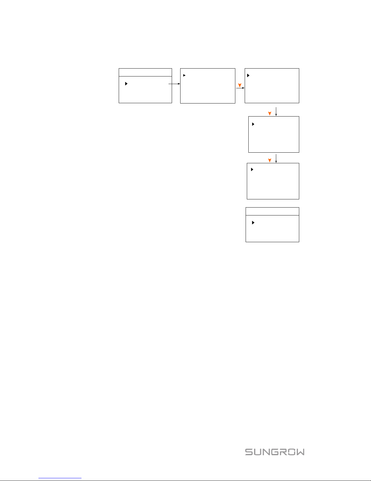
When the grid voltage or frequency
reaches the recovery value, the
corresponding fault code displayed on
the LCD will be c
leared and the
inverter can start operating.
Vmax-recover
Vmin-recover
253.0V
195.5V
Fmax-recover
Fmin-recover
50.05Hz
47.50Hz
Power Ramp Rate (for countries except Great Britain):
the ramp up/down rate of power variation.
The power rate limit mode is enabled (ON) by default.
Set to OFF to turn off the function.
Power Ramp Rate
En.
[ ON ]
10.00%
Power Ramp Rate
10-minute over-voltage protection (for countries
except Great Britain):
The inverter will automatically disconnect from the grid
within 3 s when the average voltage for a 10 min period
exceeds the set-point of 10-min Over Vtg.
Set to OFF to turn off the function.
10-min Over Vtg
253.0V
10-min Over Vtg En.
[
ON ]
Tab. 5-2 Protective Parameter Explanations
Parameter
Explanation
Vmax-recover
Recovery value for over-voltage fault. Inverter can start
operating only when the grid voltage is below this value.
Vmin-recover
Recovery value for under-voltage fault. Inverter can start
operating only when the grid voltage is above this value.
Fmax-recover
Recovery value for over-frequency fault. Inverter can start
operating only when the grid frequency is below this value.
Fmin-recover
Recovery value for under-frequency fault. Inverter can start
operating only when the grid frequency is above this value.
Power Ramp
Rate
The ramp rate of power variation.
10-min Over Vtg
Over-voltage protection value of 10-min average voltage
Reconnect Time
For Italy only.
Page 48
5 LCD Operation Quick User Manual
38
5.6 Setting the Communication Parameters
Comm.
Param
Ethernet Config
WiFi Config
IP
:
192.168.001.100
Sub Net:
255.255.000.000
Press
DHCP
[ON]
Addr 001
Port 00502
Ethernet:
− The communication address ranges from 1 to
247.
− The IP, sub net, gateway, DNS1 and DNS2 can
be modified only when the DHCP is set to OFF.
− Acquire the IP, subnet mask, gateway, DNS1 and
DNS2 from the network professional.
192.168.100.002
Gateway:
InfoBank [ON]
DNS [ON]
001.002.004.008
DNS2
008.008.008.008
DNS1
Press
Press
Wi-Fi:
Press ENT to enable this function and then you can
connect the inverter Wi-
Fi to your home router
quickly with SolarInfo Moni APP. For details, see the
manual delivered with the Wi-Fi module.
WiFi Config
Quick Config
WiFi Factory Reset
Page 49
39
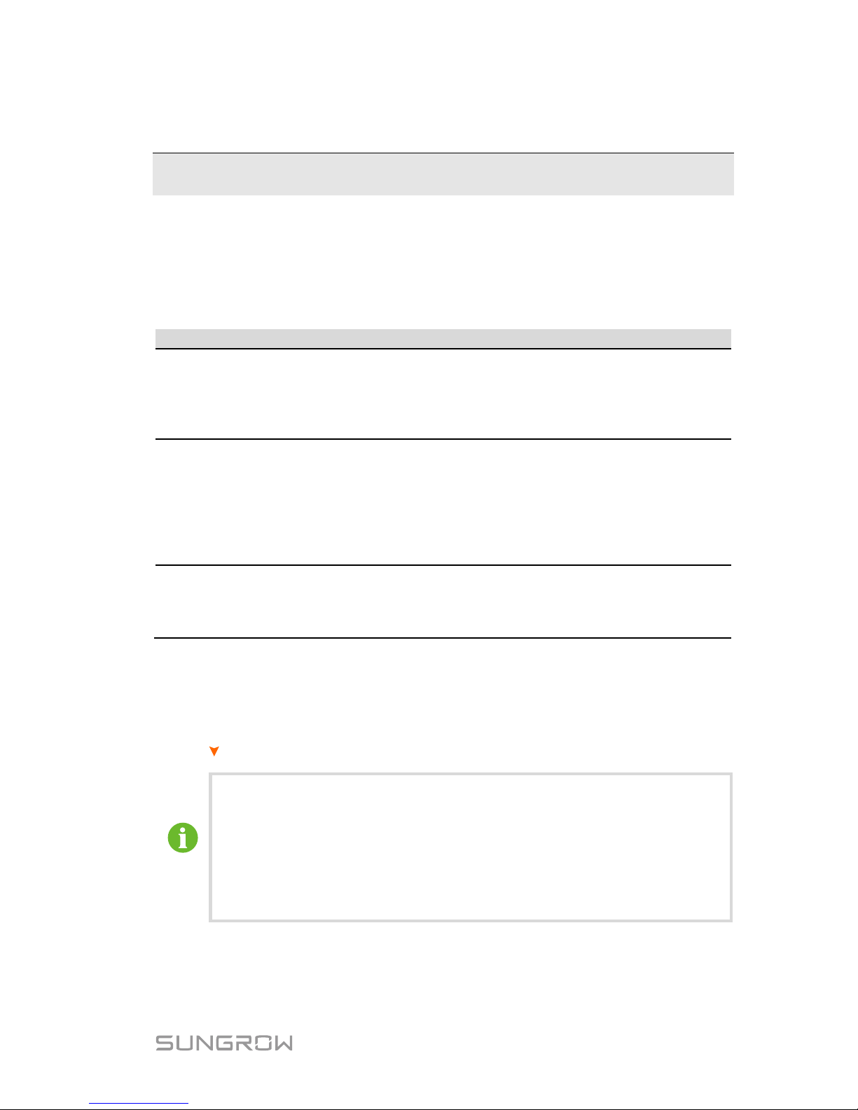
6 Troubleshooting
6.1 Troubl eshooting of the Indicator
Refer to “Ta b . 3-2 Status Descriptions of the Indicator“ for the definition of
indicator statuses.
Fault Type
Troubleshooting
The indicator
and LCD
screen cannot be lit.
1. Disconnect the AC circuit breaker.
2. Rotate the DC Switch to “OFF”.
3. Check the polarities of the DC inputs.
4. If all of the above are OK, please contact
SUNGROW.
The indicator goes out
from green.
1. Disconnect the AC circuit breaker.
2. Rotate the DC Switch to “OFF”.
3. Check the electrical connection.
4. Check whether the DC input voltage exceeds the
start voltage of the inverter.
5. If all of the above are OK, please contact
SUNGROW.
The indicator is lit red.
1. A fault is not resolved.
2. Perform troubleshooting according to the fault type
on the LCD screen.
3. If the fault persists, please contact SUNGROW.
6.2 Troubl eshooting of the Errors
When an error occurs, the “Error” status will be shown on the main screen.
Press
to view all the error information.
For the battery error codes, if all the conditions are OK but the error
still occurs, contact the distributor or the battery manufacturer.
We need the following information to provide you with
the best
assistance: inverter type (e.g. string, central, grid-connected,
hybrid, transformerless, singl
e phase, triple phase, single MPPT,
multiple MPPTs), or product name, serial number of the inverter,
fault code/name, and a brief description of the problem.
Page 50
6 Troubleshooting Quick User Manual
40
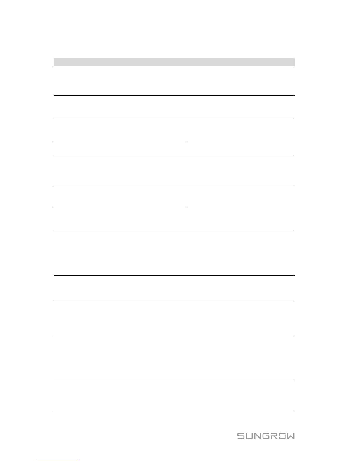
For Inverter Side
Code
Specification
Troubleshooting
002
Grid over-voltage.
(default range: 264.5 V)
1. Check the grid voltage.
2. If the grid voltage exceeds the
permissible range, consult the
utility grid for a solution.
003
Temporary grid over-voltage in
the on-grid mode.
(default value: 400 V)
This is a short-term fault.
Wait a moment for inverter
recovery or restart the system.
004
Grid under-voltage.
(default range: 184.0 V–195.5
V)
1. Check the grid voltage.
2. If the grid voltage exceeds the
permissible range, consult the
utility grid for a solution.
005
Grid under-voltage.
(default value: 195.5 V)
007
Temporary AC over-current.
The transient AC current has
exceeded the allowable upper
limit.
W
ait a moment for inverter
recovery or restart the system.
008
Grid over-frequency.
(default range: 50.5 Hz–51.5
Hz)
1. Check the grid frequency.
2. If the grid frequency exceeds
the permissible range, consult the
utility grid for a solution.
009
Grid under-frequency.
(default range: 47.5 Hz–49.5
Hz)
010
Islanding.
Abnormal connection between
the system and the grid.
1. Check whether the AC circuit
breaker is triggered.
2. Check whether all the AC
cables are firmly connected.
3. Check whether the grid is in
service.
011
DC injection over-current.
The DC injection of the AC
current exceeds the upper limit.
W
ait a moment for inverter
recovery or restart the system.
012
Leakage current over-current.
The leakage current exceeds
the upper limit.
1. Check whether there is a
grounding fault in the PV strings.
2. W
ait a moment for inverter
recovery or restart the system.
014
10-minute grid over-voltage.
The average grid voltage is
outside the permissible range
for over 10 minutes.
(default range: 253.0 V–257.6
V)
1.
Check whether the grid is
operating normally.
2. W
ait a moment for inverter
recovery or restart the system.
015
Grid over-voltage.
(default value: 264.5 V)
1. Check the grid voltage.
2. If the grid voltage exceeds the
permissible range, consult the
utility grid for a solution.
Page 51
Quick User Manual 6 Troubleshooting
41
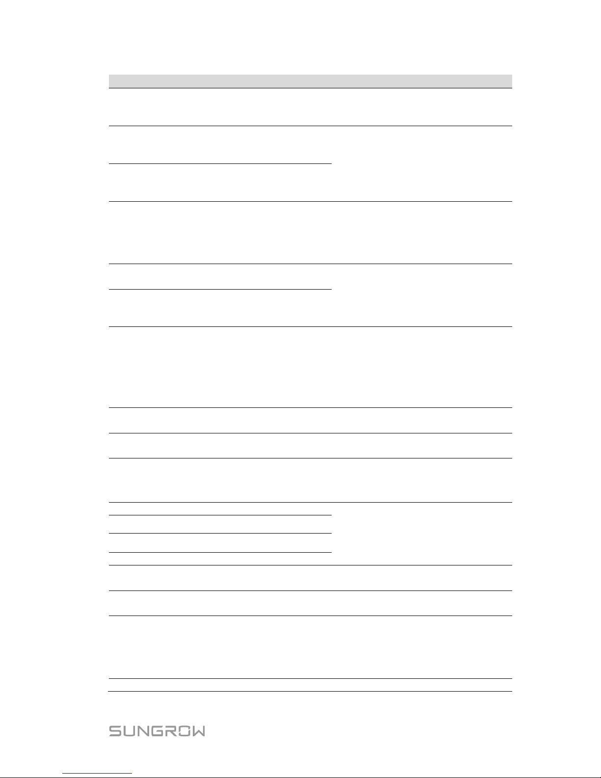
Code
Specification
Troubleshooting
019
Bus over-voltage.
The transient
bus voltage
exceeds the upper limit.
W
ait a moment for inverter
recovery or restart the system.
021
PV1 over-current.
The input current of PV1
exceeds the upper limit.
1. Check the PV input power and
configuration.
2. W
ait a moment for inverter
recovery or restart the system.
022
PV2 over-current.
The input current of PV2
exceeds the upper limit.
024
Neutral point voltage
imbalance.
The deviation of the neutral
point voltage exceeds the
allowable limit.
1. The inverter will recover once
the deviation f
alls below the
protective limit.
2. W
ait a moment for inverter
recovery or restart the system.
028
Reverse polarity of the PV1
connection.
1. Disconnect the DC switch.
2. Check the polarity of the PV
inputs.
3. Reconnect the PV strings if the
polarity is incorrect.
029
Reverse polarity of the PV2
connection.
037
Inner over-temperature fault.
The ambient temperature
inside the inverter exceeds the
upper limit.
1. Check and clean the heat sink.
2. Check whether the inverter is
installed in sunlight or the ambient
temperature of the enclosure
exceeds 45 ℃
. If not, please
contact SUNGROW for a solution.
038 Relay fault on the grid side.
Wait 5 minutes for inverter
recovery or restart the system.
041,
622
Leakage current sampling fault.
Wait 5 minutes for inverter
recovery or restart the system.
043
Inner under-temperature fault.
The a
mbient temperature
inside the inverter is too low
The inverter will recover once the
ambient temperature rises above
-25
℃.
044
INV open-loop self-check fault.
Wait 5 minutes
for inverter
recovery or restart the system.
045 PV1 boost circuit fault.
046 PV2 boost circuit fault.
048
Phase current sampling fault.
051
Load overpower fault in the
off-grid mode.
If the fault persists, disconnect
some non-key loads.
052
INV under-voltage fault in the
off-grid mode.
Wait 5 minutes for inverter
recovery or restart the system.
062
DI fault of the backup box
STB5K.
1. Check whether the DI
connection between the inverter
and the backup box is correct.
2. W
ait 5 minutes for inverter
recovery.
063
The version of CPLD (complex
Power off the system and program
Page 52
6 Troubleshooting Quick User Manual
42
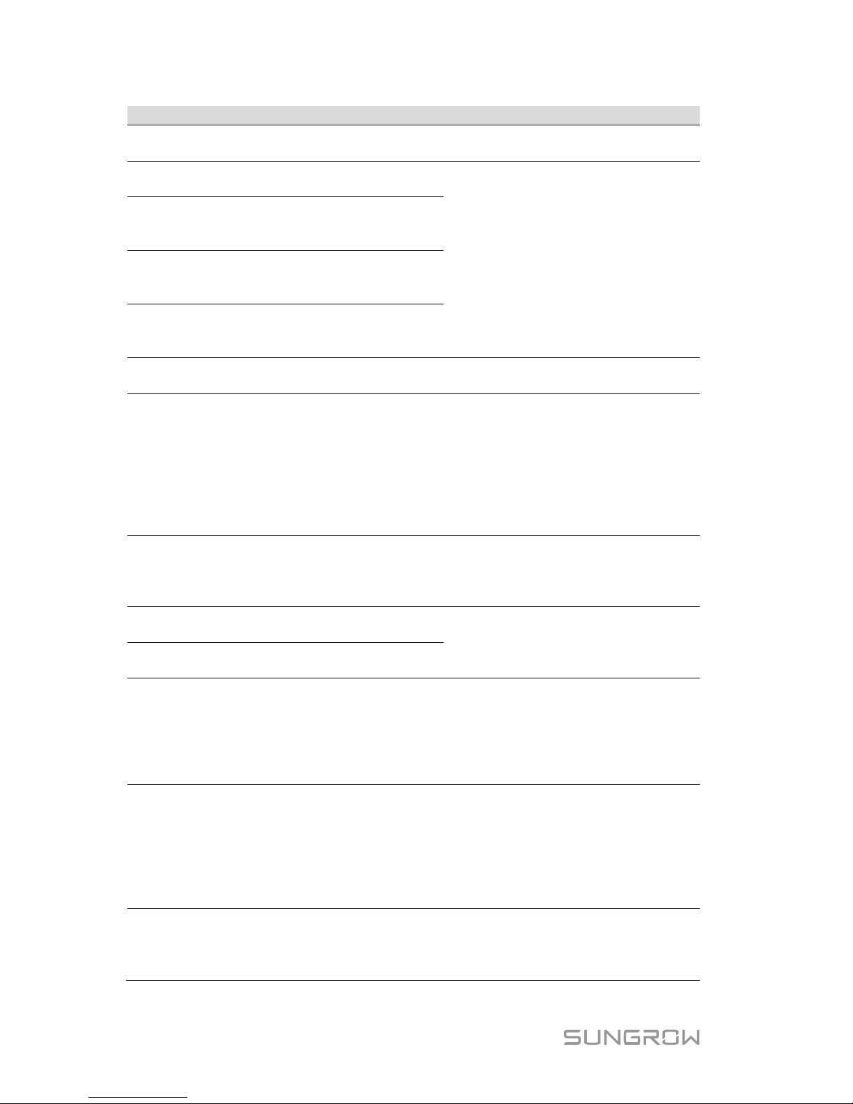
Code
Specification
Troubleshooting
programmable logic device)
cannot be detected.
the CPLD
064
INV over-voltage fault in the
off-grid mode.
Wait 5 minutes fo
r inverter
recovery or restart the system.
065
INV under-frequency fault in
the off-grid mode.
(default value: 47 Hz)
066
INV over-frequency fault in the
off-grid mode.
(default value: 52 Hz)
067
Temporary grid over-voltage in
the off-grid mode.
(default value: 500 V)
083 Fan2 abnormal speed warning.
1. Check if the fan is blocked.
2. Restart the system.
084
Warning for r
everse cable
connection of the Sungrow
Meter.
1. Check whether the po wer cable
connections are correct.
2. For Sungrow single-phase
meter, check whether the CT
clamp of the 1-phase sensor is
correctly placed. Refer to “3.3.1
Meter Installation and
Connection”.
100
INV hardware over-current
fault.
The AC current exceeds the
protective value.
Wait 5 minutes
for inverter
recovery or restart the system.
101
Grid over-frequency.
(default value: 51.5 Hz)
Check the grid frequency.
102
Grid under-frequency.
(default value: 47.5 Hz)
105
SPI auto test
fault (for Italy
only)
1. Clear the fault via the LCD
menu.
2. Restart the system and re-do
the auto test if necessary.
3. If the fault persists, please
contact SUNGROW for a solution.
106
Earth fault.
Neither the PE terminal on the
AC connection block nor the
second PE terminal on the
enclosure is reliably connected.
1. Check whether there is a
reliable grounding connection.
2. If there is acces s to the ground,
and the fault still exists, please
contact SUNGROW for a solution.
3. Check whether the L-line and
N-line are connected correctly.
107
DC injection over-voltage fault
in the off-grid mode.
The DC injection of INV voltage
exceeds the upper limit.
The inverter will recover once the
DC injection
voltage falls below
the recovery value.
Page 53
Quick User Manual 6 Troubleshooting
43
Code
Specification
Troubleshooting
200
Bus hardware over-voltage
fault.
The bus voltage exceeds the
protection value.
Wait 5 minutes
for inverter
recovery or restart the system.
201
Bus under-voltage fault.
202
PV hardware over-current fault.
The PV1 or PV2 current
exceeds the protective value.
203
The PV input voltage exceeds
the bus voltage.
Check the functionality of the PV
connection terminals.
204
PV1 boost short-circuit fault
The inverter may be damaged.
Contact SUNGROW for a solution.
205
PV2 boost short-circuit fault
300 INV over-temperature fault.
1. Check and clean the heat sink.
2. Check whether the inverter is
installed in sunlight or the ambient
temperature of the enclosure
exceeds 45℃-60℃.
3. Restart the system.
302 PV insulation resistance fault.
1. Check whether the PV cable
connection is intact.
3. Wait for a sunny day to check
whether the system can run well.
308
Slave DSP redundant fault.
Restart the system.
309
Phase voltage sampling fault.
312
DC injection sampling fault.
315
PV1 current sampling fault.
316
PV2 current sampling fault.
317
PV1 MPPT current sampling
fault.
318
PV2 MPPT current sampling
fault.
319
System power supply failure
fault.
320
Leakage current CT self-check
fault.
321
SPI communication failure.
Communication faults between
the master DSP and the slave
DSP.
322
Master DSP communication
fault.
401408
Permanent faults.
409
All temperature sensors failed
fault.
Forced restart the system.
501
FRAM1 reading warning.
1. Inverter can normally be
connected to the grid.
2. Restart the system.
503506,
Temperature sensor warnings.
Page 54
6 Troubleshooting Quick User Manual
44
Code
Specification
Troubleshooting
511
507
Error alarm of
DO power
settings.
Modify the DO control power
according to the load power. Refer
to “Optimized Control” in the user
manual.
509 Clock reset fault.
Manually reset the clock or
synchronize the clock with the
network time. This will clear the
fault.
510 PV over-voltage fault.
1. Check whether the
configuration of the PV array
exceeds the permissible range of
the inverter.
2. W
ait a moment for inverter
recovery or restart the system.
513 Fan1 abnormal speed warning.
1. Check if the fan is blocked.
2. Restart the system.
514
Abnormal communication
warning of the Sungrow Meter.
(Inverter can be normally
connected to the grid.)
1. Check whether the power cable
connections of the meter are
correct.
2. C
heck whether the RS485
connection is correct.
3. Check if the 120 Ohm (2)
resistor for RS485_2 is pushed to
“ON” when the length of RS485
cable is longer than 100 m.
600
Temporary BDC charging
over-current fault.
W
ait a moment for system
recovery or restart the system.
601
Temporary BDC discharging
over-current fault.
602
Clamping capacitor
under-voltage fault.
1. Check the cable connection of
the battery.
2. W
ait a moment for system
recovery or restart the system.
603
Temporary clamping capacitor
over-voltage fault.
W
ait a moment for system
recovery or restart the system.
608
BDC circuit self-check fault.
612 BDC over-temperature fault.
1. Check and clean the heat sink.
2. Check whether the inverter is
installed in sunlight or the ambient
temperature of the enclosure
exceeds 45℃.
3. Restart the system.
616
BDC hardware over-current
fault.
The system will resume once the
battery charge/discharge current
falls below the upper limit or
restart the system.
620
BDC current sampling fault.
Wait a moment for system
Page 55
Quick User Manual 6 Troubleshooting
45
Code
Specification
Troubleshooting
623
Slave DSP communication
fault.
recovery or restart the system.
624
BDC soft-start fault.
800,802
804,807
BDC internal permanent faults. Restart the system
900,901
BDC
temperature sensor
warnings
1. Check and clean the heat sink.
2. Check whether the inverter is
installed in sunlight or the ambient
temperature of the enclosure
exceeds 45℃.
3. Restart the system.
906
Transformer direction
recognition error.
1. The inverter can normally be
connected to the grid but
charge/discharge has stopped.
2. W
ait a moment for system
recovery or restart the system.
910
FRAM2 warning
Restart the inverter.
For Battery Side
For the battery faults, please consult the battery manufacturer for a solution.
Code
Specification
Troubleshooting
703
B
attery average
under-voltage fault.
1. The inverter can normally be
connected to the grid but
charge/discharge has stopped.
2. Wait a moment for system recovery
or restart the system.
707
Battery over-temperature
fault.
1. The inverter can normally be
connected to the grid but
charge/discharge has stopped.
2. Check the ambient temperature of
the battery location.
3. Wait a moment for system recovery
or restart the system.
708
Battery
under-temperature fault.
711
Instantaneous battery
over-voltage.
1. The inverter can normally be
connected to the grid but
charge/discharge has stopped.
2. Wait a moment for system recovery
or restart the system.
712
Battery average
over-voltage fault.
714
Abnormal communication
between battery and the
hybrid inverter.
1. The inverter can normally be
connected to the grid but
charge/discharge has stopped.
2. Check the battery t
ype and
communication connection. For
lead-
acid batteries, you should
manually set the battery type.
3. Wait a moment for system recovery
Page 56

6 Troubleshooting Quick User Manual
46
Code
Specification
Troubleshooting
or restart the system.
715
Battery hardware
over-voltage fault.
1. The inverter can normally be
connected to the grid but
charge/discharge has stopped.
2. Wait a moment for system recovery
or restart the system.
732
Battery over-voltage
protection.
1. The inverter can normally be
connected to the grid. Charge has
stopped but discharge is allowed.
2. Wait a moment for system recovery.
733
Battery over-temperature
protection.
1. The inverter can normally be
connected to the grid but
charge/discharge has stopped.
2. Check the ambient temperature of
the battery location.
3. Wait a moment for system recovery
or restart the system.
734
Battery
under-temperature
protection.
735
Battery
charging/discharging
over-current protection.
1. The inverter can normally be
connected to the grid but
charge/discharge has stopped.
2. Wait a moment for system recovery
or restart the system.
739
Battery under-voltage
protection.
1. The inverter can normally be
connected to the grid. Discharge has
stopped but charge is allowed.
2. Wait a moment for system recovery
or restart the system.
832
Battery FET fault or
electrical switch failure.
1. The inverter can normally be
connected to the grid but
charge/discharge has stopped.
2. Check the battery port voltage and
the battery
communication cable
connection.
3. Force a shutdown and restart the
inverter and battery system.
4. Wait a moment for system recovery
or restart the system.
834
Battery
charging/discharging
over-current permanent
fault.
836 ID competing failure.
Restart the system, if the fault persists,
please contact SUNGROW for a
solution.
839
Mismatched software
version.
Contact SUNGROW for a solution.
844
Software self-verifying
failure.
Restart the system, if the fault persists,
please contact SUNGROW for a
solution.
864
Battery cell over-voltage
fault.
1. The inverter can normally be
connected to the grid but
charge/discharge has stopped.
Page 57
Quick User Manual 6 Troubleshooting
47
Code
Specification
Troubleshooting
2. Wait a moment for system recovery
or restart the system.
866
Battery precharge voltage
fault.
1. The inverter can normally be
connected to the grid but
charge/discharge has stopped.
2. Check the battery port voltage and
the battery communic
ation cable
connection.
3. Force a shutdown and restart the
inverter and battery system.
4. Wait a moment for system recovery
or restart the system.
867
Battery under-voltage
fault.
868
Battery cell voltage
imbalance fault.
870
Battery cable connection
fault.
909
Low SOH (State of
Health) warning.
1. The inverter can normally be
connected to the grid and the
charge/discharge function is normal.
2. Batteries are beyond the scope of
the warranty. It is recommended to
contact the distributor for
replacements.
932
Battery over-voltage
warning.
1. The inverter can normally be
connected to the grid. Charge has
stopped but discharge is allowed.
2. The system will resume after a
certain time of discharging.
933
Battery over-temperature
warning.
1. The inverter can normally connected
be to the grid but charge/discharge has
stopped.
2. Check the ambient temperature of
the battery location.
3. Wait a moment for system recovery
or restart the system.
934
Battery
under-temperature
warning.
935
Battery
charging/discharging
over-current warning.
1. The inverter can normally be
connected to the grid but
charge/discharge has stopped.
2. Wait a moment for system recovery
or restart the system.
937
Battery tray voltage
imbalance warning.
1. The inverter can normally be
connected to the grid and the
charge/discharge functions are normal.
2. Check whether the cable connection
of the battery is correct.
939
Battery under-voltage
warning.
1. The inverter can normally be
connected to the grid. Discharge has
stopped but charge is allowed.
2. The system will resume after a
certain time of charging.
964 Battery internal warning.
Consult the battery manufacturer for a
solution.
Page 58
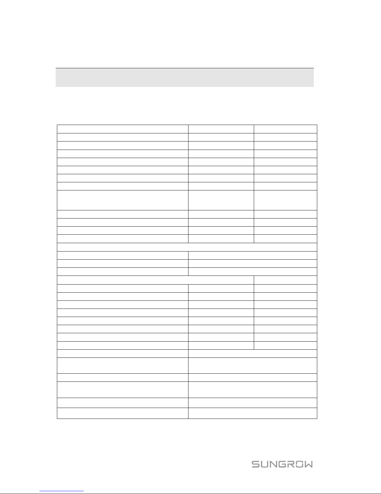
48
7 Appendices
7.1 Inverter Technical Data
PV Input Data
SH3K6
SH4K6
Max. PV input power
6500 W
6500 W
Max. PV input voltage
600 V
600 V
Startup voltage
125 V
125 V
Nominal input voltage
360 V
360 V
MPP voltage range
125 V–560 V
125 V–560 V
MPP voltage range for nominal power
180 V–520 V
220 V–520 V
No. of MPPTs
2
2
Max. number of PV strings per MPPT
(DC1/DC2)
1 / 1 1 / 1
Max. PV input current (DC1/DC2)
22 A (11 A / 11 A)
22 A (11 A / 11 A)
Max. current for input terminals
24 A (12 A / 12 A)
24 A (12 A / 12 A)
Short circuit current of PV input
24 A (12 A / 12 A)
24 A (12 A / 12 A)
Max. inverter backfeed current to array
0 A
0 A
Battery Data
Battery type
Li-ion battery / Lead-acid battery
Battery voltage (rated voltage / range)
48 V (32 V–70 V)
Max. charging / discharging current
65 A / 65 A
AC Input and Output Data
Nominal AC output power to grid
3680 W
4600 W
Max. AC output apparent power to grid
3680 VA
(1)
4600 VA
(2)
Max. AC input power from grid
3000 W
3000 W
Nominal AC output current
16 A
20 A
Max. AC output current
16 A
20 A
Max. inrush current (peak/duration)
10 A / 12 ms
10 A / 12 ms
Max. output fault current (peak/duration)
100 A/3.2 ms
100 A / 3.2 ms
Max. output over-current protection
32 A
32 A
Nominal grid voltage
230 Vac
Grid voltage range
180 Vac–276 Vac
(this may vary with grid standards)
Nominal grid frequency
50 Hz
Grid frequency range
45 Hz–55 Hz
(this may vary with grid standards)
Total Harmonic Distortion (THD) < 3 % (of nominal power)
DC current injection < 0.5 % (of nominal current)
Page 59
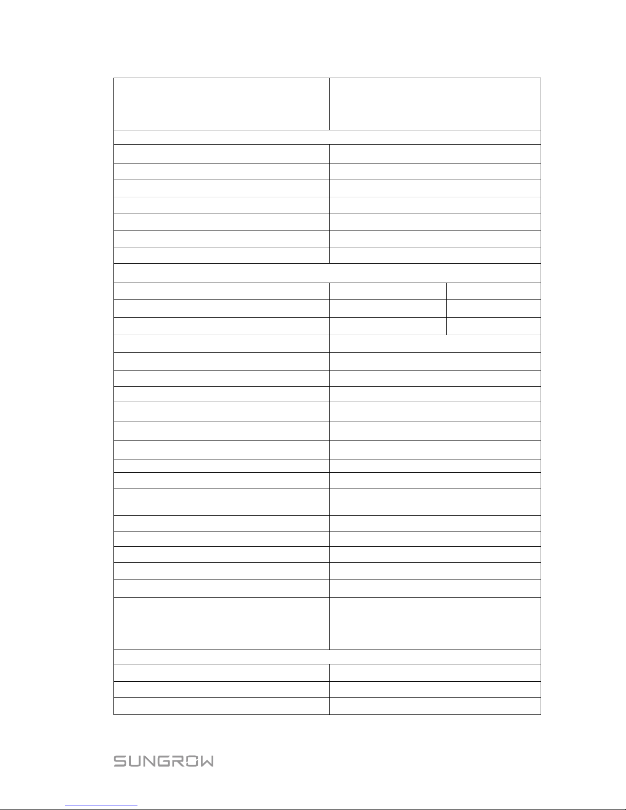
Quick User Manual 7 Appendices
49
Power factor
> 0.99 at default value at nominal
power
(adj. 0.8 overexcited/leading–0.8
underexcited/lagging)
Protection
Anti-islanding protection Yes
AC short circuit protection
Yes
Leakage current protection Yes
DC switch (solar) Yes
DC fuse (solar) No
DC fuse (battery)
Yes
Over-voltage category
III [Main], II [PV] [Battery]
System Data
Max. efficiency 97.7 % 97.7 %
Max. European efficiency
97.0 %
97.2 %
Max. charge / discharge efficiency 94.0 % 94.0 %
Isolation method (solar)
Transformerless
Isolation method (battery) HF
Ingress protection (IP) rating IP65
Power loss in night mode
< 1 W
Operating ambient temperature range
-25℃ to 60℃(> 45℃ derating)
Allowable relative humidity range 0–100 %
Cooling method Natural convection
Max. operating altitude
2000 m
Display
Graphic LCD
Communication
2 x RS485, Ethernet, Wi-Fi (optional),
CAN
Analogue input
PT1000
Power management
1 x Digital output
Earth fault alarm
1 x Digital output, email, buzzer inside
PV connection type MC4
AC connection type Clamping yoke connector
Certificates and approvals
VDE-AR-N-4105, DIN VDE0126-1-1,
G83/2, G59/3, CEI 0-21, IEC 62109-1,
IEC62109-2, EN 62477-
1, EN
61000-6-1/-3
Mechanical Data
Dimensions (W x H x D) 457 mm x 515 mm x 170 mm
Mounting method
Wall-mounting bracket
Weight 22 kg
Page 60
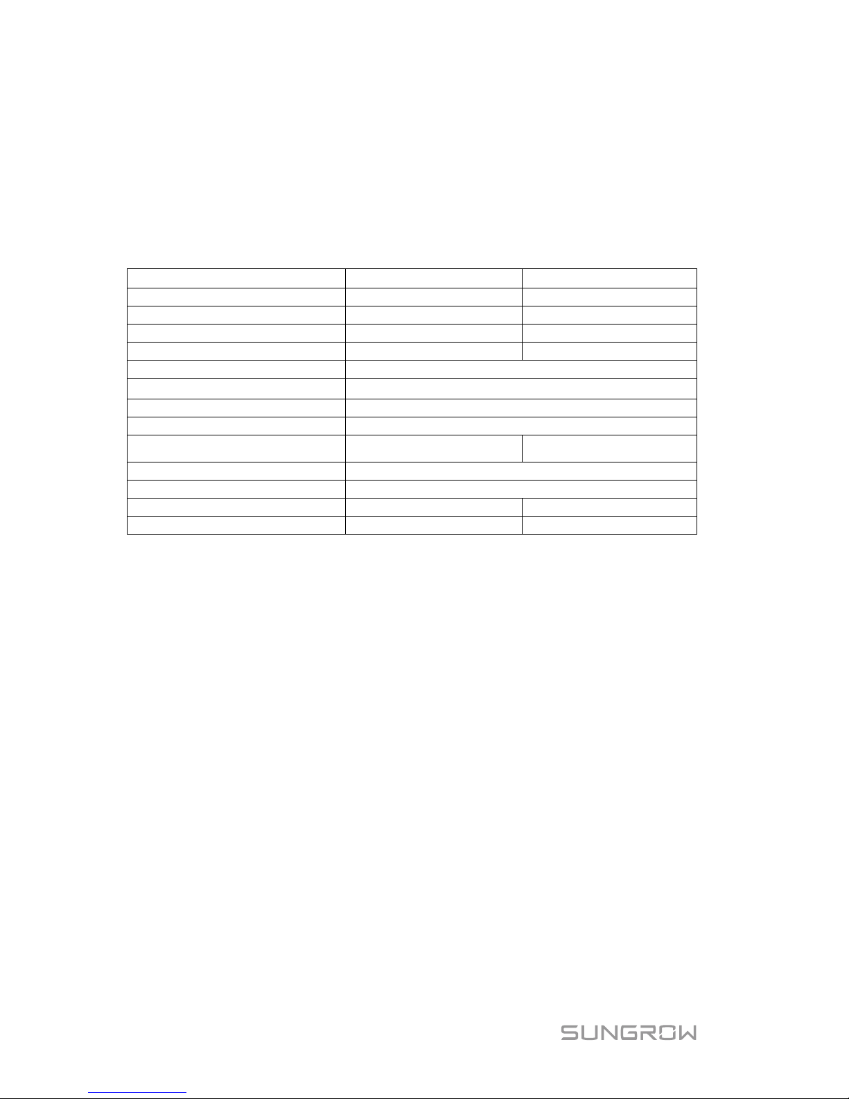
7 Appendices Quick User Manual
50
For the Q(p) mode in Italy, when the PF is 0.90 and the active power is 100 %,
(1) SH3K6: the maximum AC output apparent power to grid is 4000 VA.
(2) SH4K6: the maximum AC output apparent power to grid is 5110 VA.
7.2 Meter Technical Data
Item
Single-phase
Three-phase
Nominal voltage
240 Vac
230 Vac / 400 Vac
Input voltage range
180 Vac–286 Vac
180 Vac–276 Vac
Power consumption
< 2 W (10 VA)
< 2 W (10 VA)
Max. operating current
100 A
65 A
Grid frequency
50 Hz
Measurement accuracy
Class I
Interface and communication
RS485
Ingress protection rating
IP20
Operating temperature range
-25℃ to 75℃ -25℃ to 70℃
Allowable relative humidity
0–95%
Mounting method
35 mm DIN-rail
Dimensions (W x H x D)
18 x 117 x 65 (mm)
85 x 72 x 72 (mm)
Weight
0.2 kg
0.4 kg
Exclusion of Liability
The content of these documents is periodically checked and revised, please
contact us or visit the website www.sungrowpower.com for the latest
information. Discrepancies cannot be excluded. No guarantee is made for the
completeness of these documents. Please contact our company or distributors
to get the latest version.
Guarantee or liability claims for damage of any kind are excluded if they are
caused by one or more of the following items:
inappropriate use or installation of the products;
installing or operating the products in an unintended environment;
ignoring relevant safety regulations in the deployment location when
installing or operating the products;
ignoring safety warnings and instructions contained in all documents
relevant to the products;
installing or operating the products under incorrect safety or protection
conditions;
altering the products or supplied software without authority;
Page 61

Quick User Manual 7 Appendices
51
the product faults due to operating attached or neighboring devices beyond
allowed limit values; and
damage caused by the natural environment beyond the rated operating
range of the inverter.
The use of supplied software produced by SUNGROW is subject to the
following conditions:
SUNGROW rejects any liability for direct or indirect damage arising from the
use of the SolarInfo software. This also applies to the provision or
non-provision of support activities.
Using the SolarInfo software for commercial purposes is prohibited.
Decompiling, decoding or destroying the original program, including
SolarInfo software and the embedded software, is prohibited.
About Us
SUNGROW is a China-leading manufacturer of various power electronic
products for renewable energy generation systems, supplying to a global
customer base. Our products include converters, inverters, battery chargers
and other power supplies for distributable generation systems in both
grid-connected and stand-alone applications. The power rating of SUNGROW
products covers from hundred watt to mega-watt systems.
The vision of SUNGROW is to help our customers acquire stable and clean
power with minimum cost, maximum reliability and enhanced safety.
Contact Information
Should you have any problems, please contact us through the following
information. We will be more than happy to assist you!
Company:
Sungrow Power Supply Co., Ltd.
Website:
www.sungrowpower.com
Email:
Address:
No. 1699 Xiyou Rd., New & High Technology Industrial
Development Zone, Hefei, P. R. China.
Zip:
230088
Telephone:
+86 551 6532 7834, +86 551 6532 7845
Fax:
+86 551 6532 7856
 Loading...