

Page 1
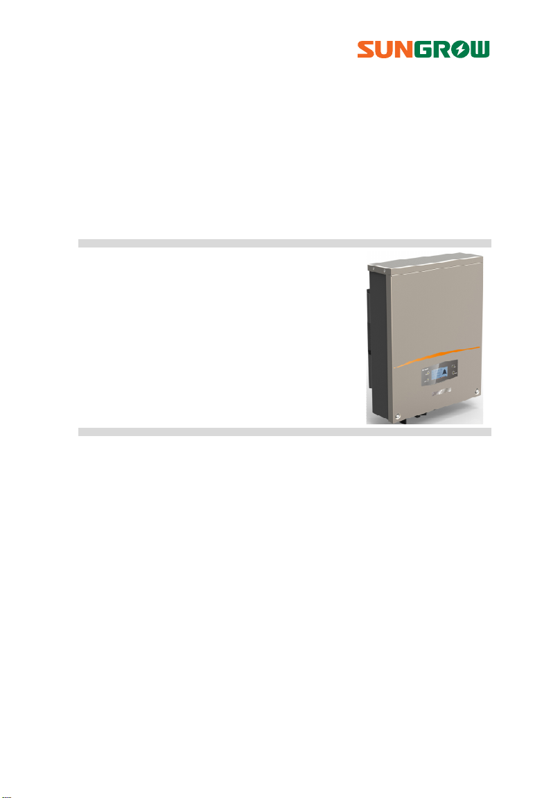
User Manual
SG3KTL-EC / SG4KTL-EC/
SG5KTL-EC / SG6KTL-EC
PV Grid-Connected Inverter
SG3_4_5_6KTL-EC-UEN-Ver15-201508 Version:1.5
Page 2

Page 3

About This Manual
This manual is for the inverters SG3KTL-EC, SG4KTL-EC, SG5KTL-EC, and SG6KTL-EC
(hereinafter referred to as inverter unless specified otherwise). They are
grid-connected, transformer-less, robust inverters with high conversion efficiency.
The devices will bring you profit for PV power system.
Aim
The manual contains information about the inverter, which will provide you
guidelines to connect the inverter into the PV power system and to operate the
inverter.
Related Documents
The manual cannot include complete information about the PV system. You will get
the additional information about other devices at www.sungrowpower.com or via
the webpage of device manufacturer.
Target Group
The manual is targeted to technical personnel who is responsible for inverter
installation and commissioning in the PV power system and inverter owner who will
perform daily LCD operation.
How to Use This Manual
Read the manual and other related documents before any work on the inverter.
Documents must be stored carefully and available at all times.
The contents of the manual will be periodically updated or revised due to product
development. It is probably that there are changes of manual in subsequent inverter
edition. The latest manual can be acquired via www.sungrowpower.com.
I
Page 4
Symbols Explanation
Important instructions contained in this manual should be followed during
installation, operation and maintenance of the inverter. And they will be highlighted
by the following symbols.
DANGER indicates a hazard with a high level of risk which, if not avoided,
will result in death or serious injury.
WARNING indicates a hazard with a medium level of risk which, if not
avoided, could result in death or serious injury.
CAUTION indicates a hazard with a low level of risk which, if not avoided,
could result in minor or moderate injury.
NOTICE indicates a situation which, if not avoided, could result in
equipment or property damage.
NOTE indicates additional information, emphasized contents or tips to
help you solve problems or save time.
II
Page 5
Symbols on the Inverter Body
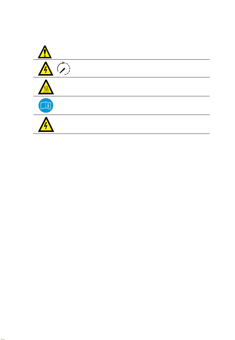
Disconnect the inverter from mains and PV generator before
service!
Do not touch any inner live parts until 10 minutes after
disconnection from the utility grid and the PV input.
Hot surface! In order to reduce the risk of burns, do not touch the
hot surface when the device is running.
Look over the user manual before any operation on the inverter!
The installation and service of the inverter unit can be performed
only by qualified personnel.
III
Page 6

Contents
About This Manual .......................................................................... I
1 Safety Instructions ................................................................... 1
2 Product Introduction ............................................................... 6
2.1 Intended Usage ...................................................................................................... 6
2.2 Product Description .............................................................................................. 7
2.2.1 Inverter Appearance ................................................................................................. 7
2.2.2 Inverter Dimensions ................................................................................................. 8
2.2.3 LCD Display Panel ...................................................................................................... 8
2.3 Technical Description ........................................................................................... 9
2.3.1 Circuit Description .................................................................................................... 9
2.3.2 Functions Description .......................................................................................... 10
3 Unpacking and Storing .......................................................... 12
3.1 Unpacking and Inspecting .............................................................................. 12
3.2 Moving the Inverter ........................................................................................... 12
3.3 Identifying the Inverter .................................................................................... 13
3.4 Delivery Contents ............................................................................................... 14
3.5 Storing the Inverter ........................................................................................... 15
4 Securing Inverter to the Wall ................................................. 16
4.1 Selecting Installation Location ...................................................................... 16
4.2 Moving Inverter to Installation Site ............................................................. 19
4.3 Installing the Inverter ........................................................................................ 20
5 Electrical Connection ............................................................. 24
5.1 Overview of Electrical Connection ............................................................... 24
5.2 Terminals Description ....................................................................................... 26
5.3 Meter Connection (optional) .......................................................................... 26
5.4 Connecting Inverter to Grid............................................................................ 27
5.4.1 AC Side Requirements .......................................................................................... 27
IV
Page 7

5.4.2 Assembling AC Cables to Connector .............................................................. 29
5.5 Connecting Inverter to PV Arrays .................................................................. 30
5.5.1 PV Inputs Configuration ...................................................................................... 31
5.5.2 Assembling DC Cable to Connector ................................................................ 33
5.5.3 DC Wiring Procedure ............................................................................................. 35
5.6 Grounding the Inverter ..................................................................................... 37
5.6.1 Grounding System Overview............................................................................. 37
5.6.2 Second Protective Earth Terminal .................................................................... 38
5.7 Communication Connection .......................................................................... 39
5.7.1 Interfaces Overview .............................................................................................. 39
5.7.2 RS485 Communication Connection ................................................................ 40
5.7.3 Ethernet Communication Connection ........................................................... 42
5.7.4 Power Control Configuration ............................................................................. 45
6 Visiting and Configuring the Webserver .............................. 49
6.1 User and Authority ............................................................................................. 49
6.2 Login Interface ..................................................................................................... 49
6.3 Main Interface ...................................................................................................... 50
6.3.1 Summary Information .......................................................................................... 50
6.3.2 Detailed Information ............................................................................................ 51
6.4 Parameter Settings ............................................................................................. 52
6.4.1 System Parameters ................................................................................................ 52
6.4.2 Operating Parameters .......................................................................................... 52
6.4.3 Protection Parameters .......................................................................................... 53
6.4.4 Communication Parameters .............................................................................. 55
6.5 History Record ...................................................................................................... 55
6.5.1 Running Record ...................................................................................................... 55
6.5.2 Fault Record .............................................................................................................. 56
6.5.3 Event Record ............................................................................................................ 56
6.6 Power Control Configuration .......................................................................... 56
6.7 System Information ............................................................................................ 57
7 Commissioning ...................................................................... 58
V
Page 8

7.1 Inspection before Commissioning ............................................................... 58
7.2 Commissioning Procedure .............................................................................. 58
8 Disconnecting, Dismantling and Disposing of the Inverter 61
8.1 Disconnecting the Inverter ............................................................................. 61
8.2 Dismantling the Inverter .................................................................................. 62
8.3 Disposing of the Inverter ................................................................................. 62
9 Troubleshooting and Maintenance ...................................... 63
9.1 Troubleshooting ................................................................................................. 63
9.1.1 Troubleshooting of LED Indicators .................................................................. 63
9.1.2 Troubleshooting of Faults on LCD Screen ..................................................... 63
9.2 Maintenance ........................................................................................................ 68
9.2.1 Routine Maintenance ........................................................................................... 68
9.2.2 Maintenance Instruction ..................................................................................... 69
10 Operating the LCD Menu ....................................................... 70
10.1 Description of Button Function ..................................................................... 70
10.2 Inverter Menu Structure ................................................................................... 71
10.3 Main Screen .......................................................................................................... 72
10.4 Adjusting Contrast ............................................................................................. 74
10.5 Viewing Detailed Running Information ..................................................... 74
10.6 Starting and Stopping the Inverter .............................................................. 76
10.7 Inputting Password ............................................................................................ 76
10.8 Button Operation for Parameters Setting .................................................. 77
10.9 Setting Parameters ............................................................................................. 77
10.9.1 Setting the Time ................................................................................................... 77
10.9.2 Selecting the Country Code ............................................................................ 78
10.9.3 Feed Setting ........................................................................................................... 80
10.9.4 PF Setting ................................................................................................................ 80
10.9.5 Setting Communication Parameters ............................................................ 80
10.9.6 Load Default .......................................................................................................... 81
11 Viewing PV Plant Information ............................................... 83
11.1 SolarInfo Bank Connection ............................................................................. 83
VI
Page 9

11.1.1 For Common User ................................................................................................ 83
11.1.2 For Professional User .......................................................................................... 84
11.2 Registration and Adding PV Plant ................................................................. 87
11.3 Viewing Information via the APP ................................................................... 91
11.3.1 Acquisition and Installation of the APP ....................................................... 91
11.3.2 SolarInfo Home APP Online Registration .................................................... 94
11.3.3 Visit in “[Direct visit]”mode ............................................................................... 95
11.3.4 Visit in “Remote [Login]”mode ........................................................................ 97
12 Appendix ................................................................................ 98
12.1 Technical Data ...................................................................................................... 98
12.2 Exclusion of Liability ........................................................................................ 100
12.3 About Us .............................................................................................................. 101
VII
Page 10

Page 11
1 Safety Instructions
IMPORTANT SAFETY INSTRUCTIONS
The inverters have been designed and tested strictly according to the international
safety regulations. As electrical and electronic equipments, safety instructions
related to them must be complied with during installation, commissioning,
operation and maintenance. Incorrect operation or work may result in damage to
the life and well-being of the operator or a third party, or
the inverter and other properties that belong to the operator or a third party.
Therefore, the following general safety instructions must be read and always kept in
mind prior to any work. All detailed work-related safety warnings and notes will be
specified at the critical points in corresponding chapter.
All installation and electrical work must be performed only by qualified
personnel. They have
been trained specially;
already read through and understood the manual and other related
documents;
been familiar with safety requirements for electrical system.
Technical personnel mentioned above may perform the following work:
Install the inverter onto the wall.
Connect the inverter into the PV power system.
Connect other devices into the PV power system.
Commission the inverter.
Maintain and service the inverter.
1
Page 12
1 Safety Instructions User Manual
Before Installation
There is a risk of injury due to improperly handling the device!
Always follow the instructions contained in the manual when moving and
positioning the inverter.
The weight of the equipment can cause injuries, serious wounds, or bruise
if improperly handled.
The device is thoroughly tested and strictly inspected before delivery.
Damage may still occur during shipping.
If there is visible damage to the packaging or the inner contents, or
anything missing, contact the device dealer.
During Installation
Prior to installing the inverter onto the wall, it is crucial to make certain that
the inverter is not electrically connected.
System performance loss due to bad ventilation!
The device requires good ventilation during operation. It is essential to keep
the device upright and nothing covering the heat sink to ensure that the
device interior is well cooled down.
During Electrical Connection
All electrical connections must be in accordance with local and national
standards.
Only with the permission of the local energy sector, the inverter can be
connected into the utility grid.
2
Page 13
User Manual 1 Safety Instructions
Lethal voltage!
PV arrays will produce electrical energy when exposed to sunlight and thus
can create an electrical shock hazard.
Wiring of the PV arrays should be performed only by qualified personnel.
All cables must be firmly attached, undamaged, properly insulated and
adequately dimensioned.
During Inverter Operation
Do not open the enclosure when the inverter is under voltage. There is a highly
unlikely risk of explosion in very specific cases of fault. The enclosure will protect
persons and property from such an explosion, only if it is correctly sealed.
There is a risk of inverter damage or personal injury!
DO NOT disconnect DC connectors while the inverter is under AC load! First
de-energize the device from dual power sources and then verify that there is
no voltage present.
There is a risk of burn!
DO NOT touch the device hot parts (such as heat sink) during operation.
Only LCD display panel and DC switch can be touched during inverter
operation.
3
Page 14
1 Safety Instructions User Manual
Maintenance and Service
Always keep in mind that the inverter is power supplied by dual power
sources: PV arrays and utility grid.
There is a risk of inverter damage or personal injury due to incorrect service
work!
Before any service work, you should obey the following procedures.
Disconnect the inverter from the utility grid first and then PV arrays;
Wait at least 10 minutes until the inner capacitors discharge completely;
Verify that no voltage and current is present with appropriate testing
device.
Keep non-related persons away!
A temporary warning sign and barrier must be posted to keep non-related
persons away in any period while performing electrical connection and
service work.
Any fault that may impair the inverter safety functions must be repaired
immediately before the inverter is restarted.
Inverter contains no owner serviceable parts inside. Please contact local
authorized personnel if any service work is required.
Servicing of the device in accordance with the manual should never be
undertaken in the absence of proper tools, test equipments or more
recent revision of the manual which is clearly and thoroughly
understood.
There is a risk of inverter damage if it is improperly serviced.
Use only accessories and spare parts approved by the inverter
manufacturer. Never modify the inverter or its components. Otherwise, it
will cause loss of any or all warranty rights.
4
Page 15
User Manual 1 Safety Instructions
There is a risk of inverter damage due to electrostatic discharge!
The printed circuit boards contain components sensitive to electrostatic
discharge. Wear a grounding wrist band when handling the boards. Avoid
unnecessary touch with the boards during replacement.
Others
The selected country settings can be changed only by service personnel!
Unauthorized alternation of the country settings is prohibited. Otherwise it
may cause a breach of the type-certificate marking.
All safety instructions, warning labels and nameplate on the inverter body:
Must be clearly visible;
Must not be removed, covered or pasted.
These regulations should also be followed:
The regulations related to the electricity fed into grid;
The safety instructions related to the PV arrays;
The safety instructions related to other electrical devices.
5
Page 16
k
2 Product Introduction
2.1 Intended Usage
The inverters, which are 3-phase string inverters without transformer, are crucial
units between the PV strings and utility grid in the small-scaled PV power system.
Inverter is dedicated to converting the DC power generated by the PV modules into
AC power, which conforms to the parameters of local utility grid, and feeds the
alternating current into the utility grid. The intended usage of the inverter is
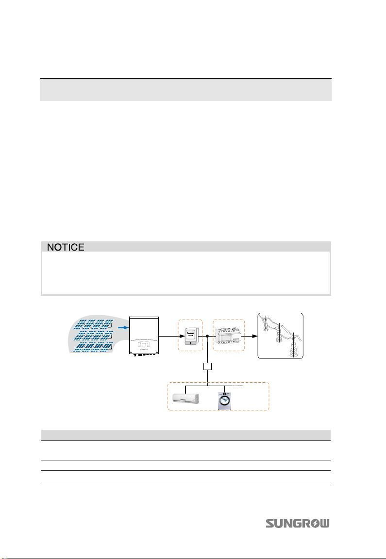
illustrated in Fig. 2-1.
By setting the upper limit of feed power, the inverter will run with power derating
once the meter detects that the output power is greater than the set value.
Any other or additional usage is not permitted except the intended usage.
Neither the DC positive pole nor the DC negative pole of the PV strings is
permitted to be grounded.
Grid Dispatch Center
AB
C
K
Jumper switch
D
Household Load
E
F
Fig. 2-1 Inverter Application in the PV Power System
Item Description Remar
A PV strings Monocrystalline silicon, polycrystalline silicon, and
thin-film of protection class II without grounding.
B Inverter SG3KTL-EC, SG4KTL-EC, SG5KTL-EC and SG6KTL-EC.
C Metering device Meter cupboard with power distribution system.
6
Page 17
User Manual 2 Product Introduction
k
Item Description Remar
D Smart energy
meter (optional)
E Utility grid TT, TN-C, TN-S, TN-C-S.
F Household load Household appliances.
Three-phase electronic energy meter, used to measure
the active power output. Communicate with the
inverter via RS485 port.
2.2 Product Description
2.2.1 Inverter Appearance
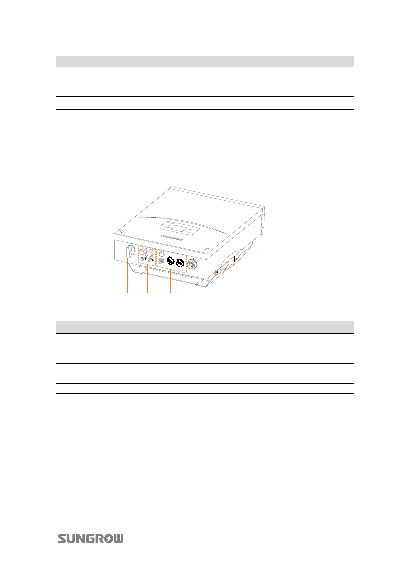
1
2
3
4657
Fig. 2-2 Inverter Appearance
No. Name Description
1 LCD display panel Human-computer interaction interface for looking
2 Side grips The side grips are designed for holding the unit
3 Second PE terminal As specified in EN 50178.
4 AC connection terminal Inverter feeds power to utility grid via this terminal.
5 Communication
connection terminals
6 DC terminals There are two pairs of DC terminals for PV input on
7 DC switch During normal operation it is in “ON” state. It can
7
up running information and configuring
parameters.
when mounting, moving or servicing the inverter.
They are RS485 terminal, Wi-Fi terminal, NET
terminal and DI terminal.
the bottom of the inverter.
shut down the inverter in “OFF” position.
Page 18
2 Product Introduction User Manual
2.2.2 Inverter Dimensions
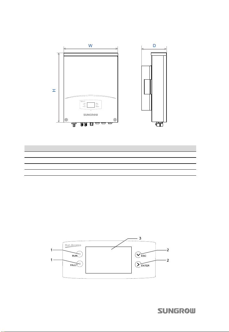
Fig. 2-3 Outline Dimensions
Tab. 2-1 Dimension Values
Type W(mm) H(mm) D(mm) Net weight(kg)
SG3KTL-EC 403 518 190 22
SG4KTL-EC 403 518 190 22
SG5KTL-EC 403 518 190 22
SG6KTL-EC 403 518 190 22
2.2.3 LCD Display Panel
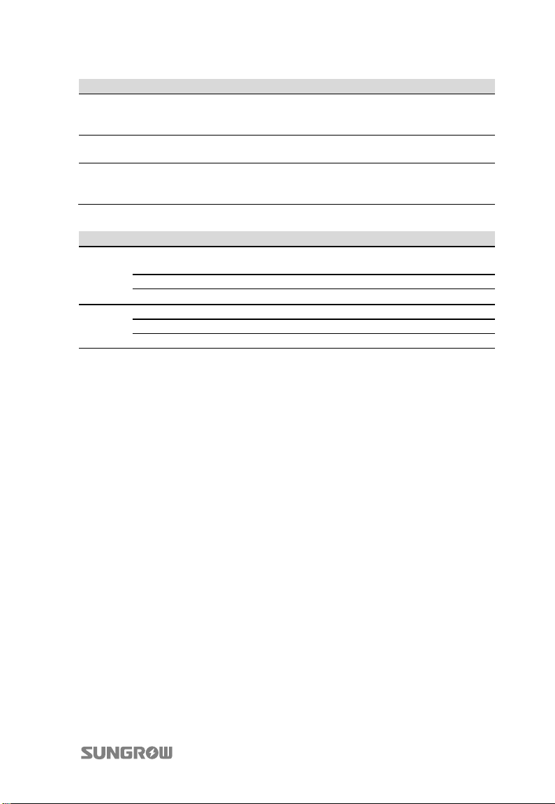
As a human-computer interaction interface, LCD display panel is on the front panel
and comprises LED indicators, buttons and LCD screen.
LED indicators indicate the working status of the inverter.
By pressing the buttons user can look up information and configure parameters.
LCD screen shows the current running information.
Fig. 2-4 LCD Display Panel
8
Page 19
User Manual 2 Product Introduction
No. Name Description
1 LED indicators “RUN” and “FAULT”. The current running state can be
2 Buttons User can operate the LCD menu via the two buttons.
3 LCD Screen LCD screen can display the current state, current running
Tab. 2-2 Description of LED Indicators
known from the two indicators. Detailed definition is
shown in Tab. 2-2.
Detailed function is shown in Tab. 10-1.
information, historical information, and parameters to be
set.
Name State Description
The inverter is feeding power to the utility grid or in derating
operation.
“RUN”
“FAULT”
On
Blinking The inverter is in the process of startup.
Off Other states.
On Communication error, permanent fault, or upgrade failure.
Blinking Other faults (alarms excluded).
Off No fault occurs.
2.3 Technical Description
2.3.1 Circuit Description
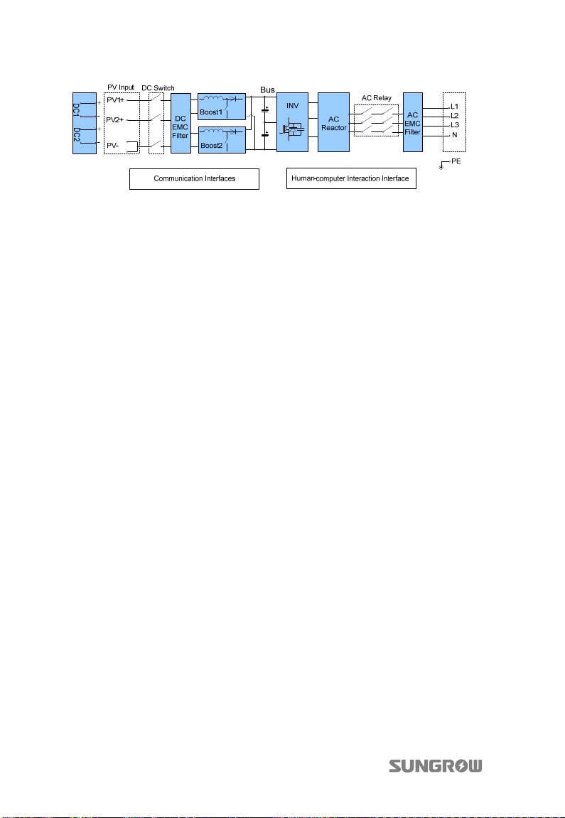
Fig. 2-5 shows the main circuit of the inverter.
The boost circuits raise the input DC voltage. Two string MPP trackers can be utilized
to ensure the maximum power from PV arrays.
The three-level inverter circuit converts the DC power into AC power, which will be
fed into the utility grid via AC terminal.
Meanwhile inverter is equipped with protective circuit to guarantee its safety
operation which can trigger the AC relay if required.
Additionally, a DC switch is integrated for safe disconnection of DC current.
The inverter provides RS485 port, Wi-Fi terminal, and NET port for communication.
Users can look up running information and set parameters through LCD display
panel.
9
Page 20
2 Product Introduction User Manual
Fig. 2-5 Main Circuit Diagram of inverter
2.3.2 Functions Description
Inverter functions can be grouped as the following:
Conversion function
Inverter converts the DC power into AC power, which conforms to the grid
requirements of its installation country.
Parameters configuration
Inverter provides various parameters configuration for optimal operation.
Communication interfaces
RS485 serial communication with RJ45 port (RS485), Ethernet communication
with RJ45 port (NET), Wi-Fi and DI connection terminals.
Earth fault alarm
With a standard Ethernet interface and a Wi-Fi terminal equipped, the inverter
can be connected to the router via a network cable or the Wi-Fi antenna. Then
both the inverter information and alarm signals will be uploaded to the cloud
server SolarInfo Bank. When the server receives an earth fault signal, it will
automatically send warning e-mail to the registered user.
Zero export (0% feed-in function, optional)
At the grid-connection point, the three-phase SUNGROW Energy Meter is used
for measuring the feed-in power. Enable the feed setting and set the limit value
via the LCD menu. Then the inverter will run with power derating once the meter
detects that the feed-in power is above the set value.
Protection functions include:
− Short circuit protection
− Insulation resistance detection and alarm
− Inverter output voltage monitoring
− Inverter output frequency monitoring
10
Page 21

User Manual 2 Product Introduction
− Residual current monitoring
− DC injection of AC output current surveillance
− Anti-islanding protection
− DC over-voltage protection
− DC over-current protection
− Power module over-temperature protection
11
Page 22
3 Unpacking and Storing
3.1 Unpacking and Inspecting
The device is thoroughly tested and inspected before delivery. Although sturdy
packaging is used, damage may still occur during shipping.
If there is visible damage to the packaging or the inner contents, or anything
missing, contact the device dealer.
Do not dispose of the original packaging. It is the best choice to store the inverter in
the original packaging.
During unpacking, cut green plastic straps and lift full upper-part of the carton box.
Do not cut the sticky tape.
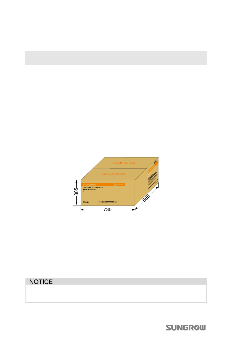
Fig. 3-1 Single Inverter in Original Packaging Carton(unit: mm)
3.2 Moving the Inverter
In order to avoid damage to the inverter during moving, it is better to move inverter
in the original carton.
Pay attention to the weight. Proper device that can bear the weight is needed to
avoid inverter damage or person injury when moving.
When moving the inverter, please follow the symbol instructions on the
packaging box.
12
Page 23
User Manual 3 Unpacking and Storing
3.3 Identifying the Inverter
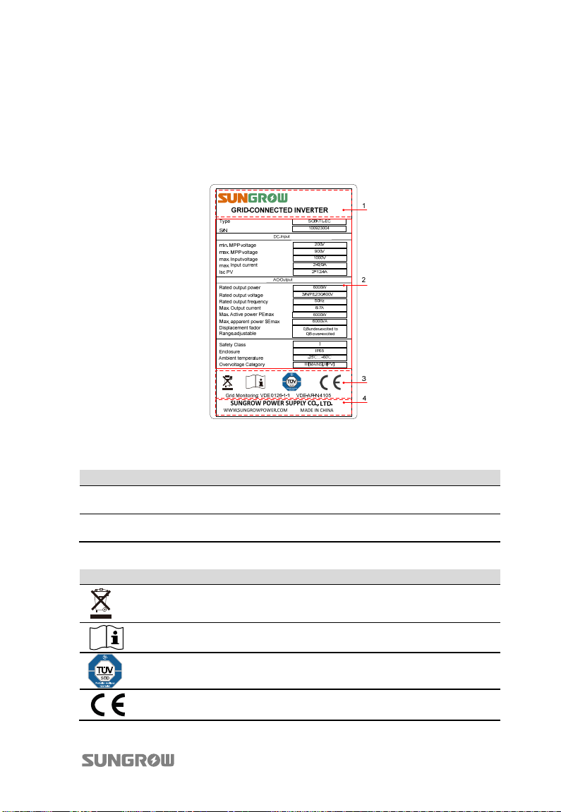
Two nameplates are attached to the side of the inverter and the carton respectively.
They provide information about the inverter type, the most important specifications,
marks of certification institutions, website and serial number which are available
and identified by SUNGROW.
Fig. 3-2 Nameplate of Inverter
*Image shown here is for reference only. Actual product you receive may differ.
Item Description Item Description
1 SUNGROW logo and product
type
2 Technical data 4 Company name, website and
Tab. 3-1 Description of Icons on the Nameplate
3 Marks of certification institutions
origin
Icon Description
Do not dispose of the inverter with the household waste.
Refer to the corresponding instructions.
TUV mark of conformity.
The inverter is in compliance with directives of TUV.
CE mark of conformity.
The inverter is in compliance with directives of CE.
13
Page 24
3 Unpacking and Stor User Manual
3.4 Delivery Contents
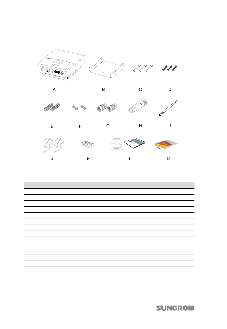
Fig. 3-3 Delivery Contents
*Image shown here is for reference only. Actual product you receive may differ.
Item Description
A Inverter.
B Wall bracket used to mount inverter onto the wall.
C Expansion bolts for fastening wall bracket onto concrete wall.
D Fastener set for installing wall bracket onto metal frame.
E PV input connectors, including positive and negative connectors.
F Two M4x12 mm screws for second PE connection.
G Waterproof communication connectors.
H AC connector.
I Wi-Fi antenna.
J Dust covers for the waterproof communication connectors.
K Six-pole plug.
L Quick User Manual and 1 CD containing User Manual and other documents.
M Quality certificates, packing list and product test reports.
14
Page 25
User Manual 3 Unpacking and Storing
3.5 Storing the Inverter
If you do not install the inverter immediately, choose an appropriate location to
store it.
The device must be stored in original packaging and the desiccant must be left in
the packaging.
The device must be stored in a clean and dry place to protect against dust and
moisture.
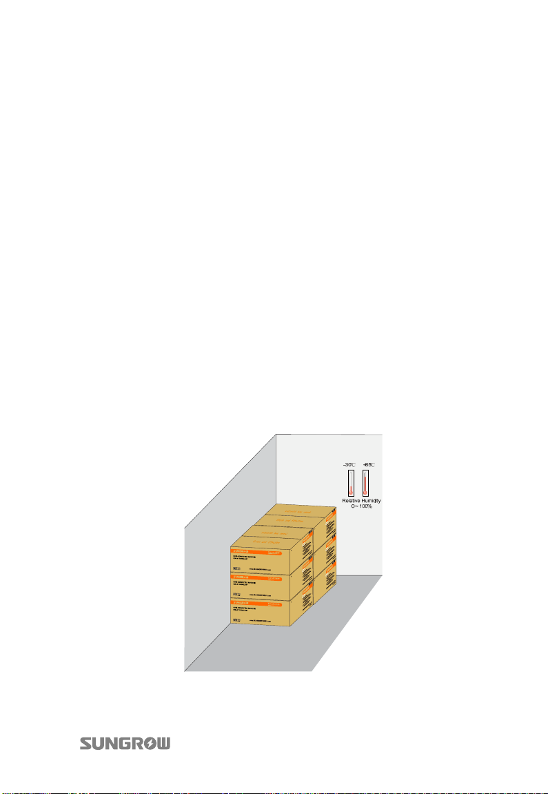
The storage temperature should be always between -30°C and +85°C. And the
storage relative humidity should be always between 0 and 100%.
It is very important to keep the packing away from chemicals. Otherwise it will
lead to corrosion.
During the storage time, check periodically for visible damages by rodents.
Replace the packaging if necessary.
If there is more than one inverter to be stored, the maximum layers for original
paper packaging are three.
After long-term storage, local installer or Service Dept. of SUNGROW should
perform a comprehensive test before connecting the inverter into PV power
system.
Fig. 3-4 Example for Inverter Storage
15
Page 26
4 Securing Inverter to the Wall
4.1 Selecting Installation Location
Selecting an optimal installation location for the inverter is decisive for its operating
safety as well as its expected efficiency and service life.
1. Take the load capacity of the wall into account. The wall (such as concrete wall and
metal structure) should be strong enough to hold the weight of the inverter over a
long period.
2. Install the device where is accessible to installing, electrical connection or service.
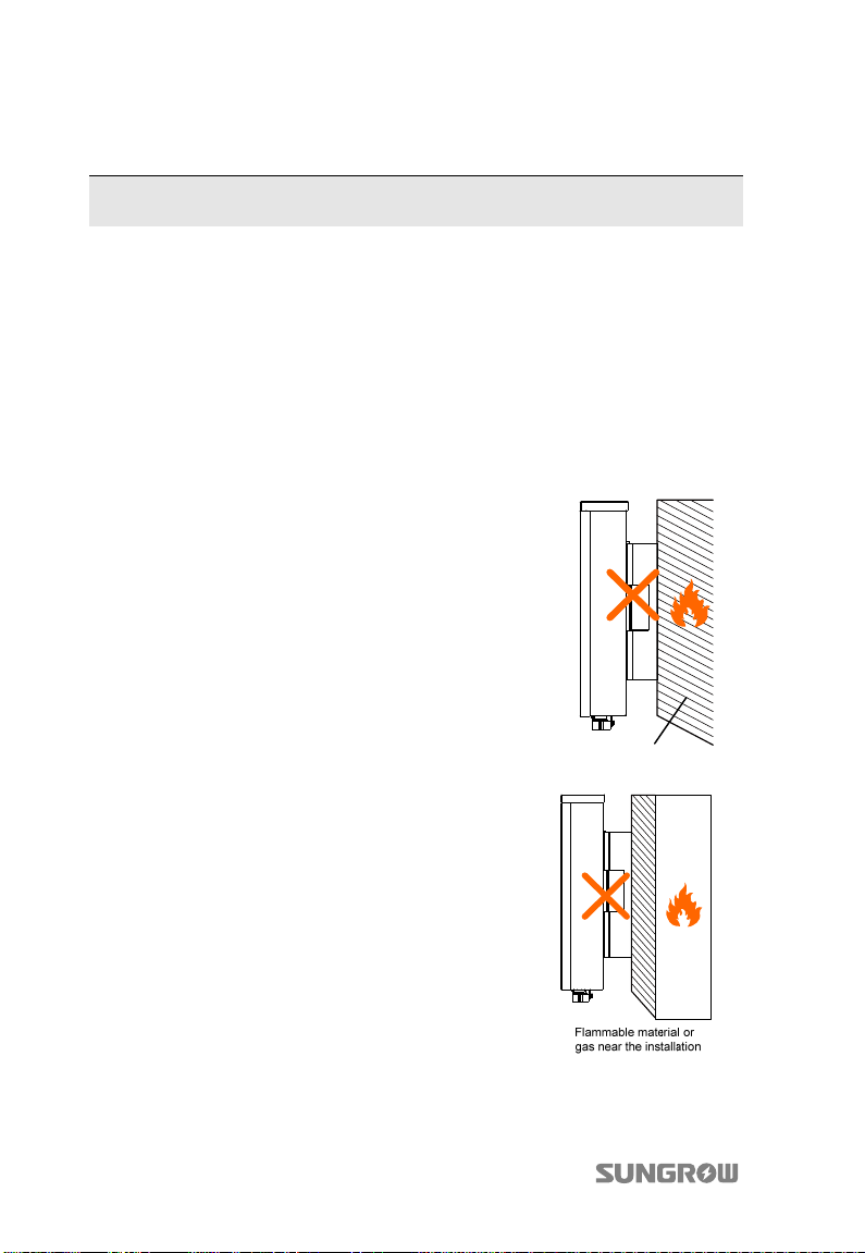
3. Do not install the device on wall of
flammable materials.
Flammable wall
material
4. Do not install the device where contains
flammable materials or flammable gas in the
vicinity of the location.
16
Page 27
User Manual 4 Securing Inverter to the Wall
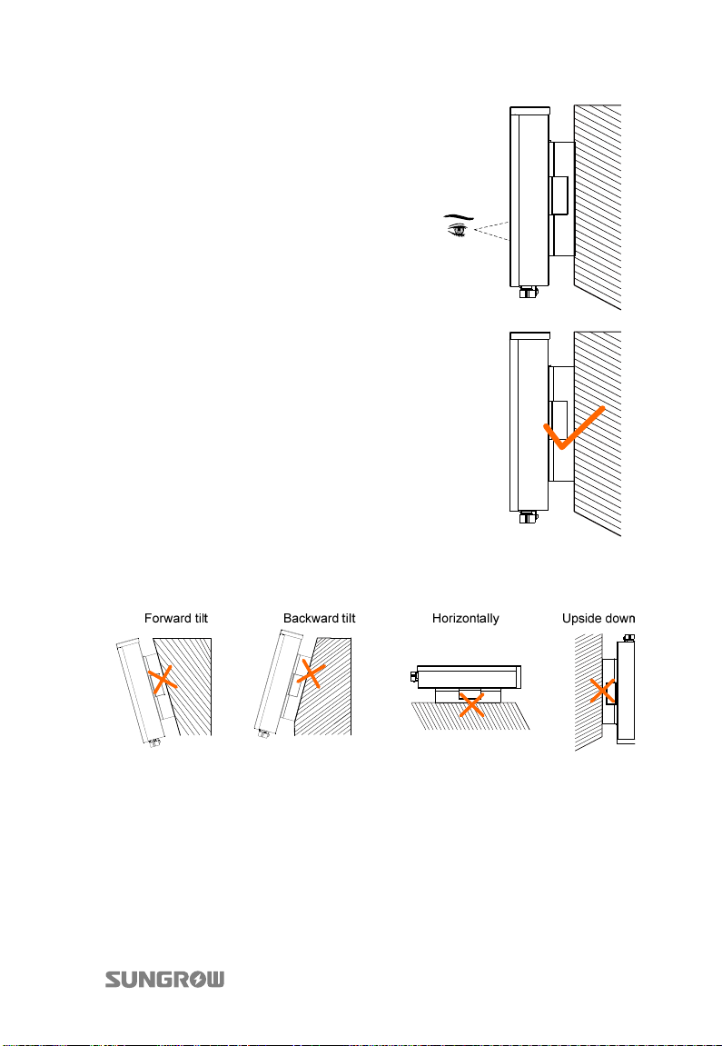
5. Install the device at eye level for easy
buttons operation and display reading.
6. It is suggested that the inverter be installed
vertically with upside up for good heat
dissipation.
7. Never install the inverter horizontally, or with a forward tilt or with a backward tilt
or even with upside down.
8. The inverter with IP65 can be installed indoors or outdoors.
17
Page 28
4 Securing Inverter to the Wall User Manual
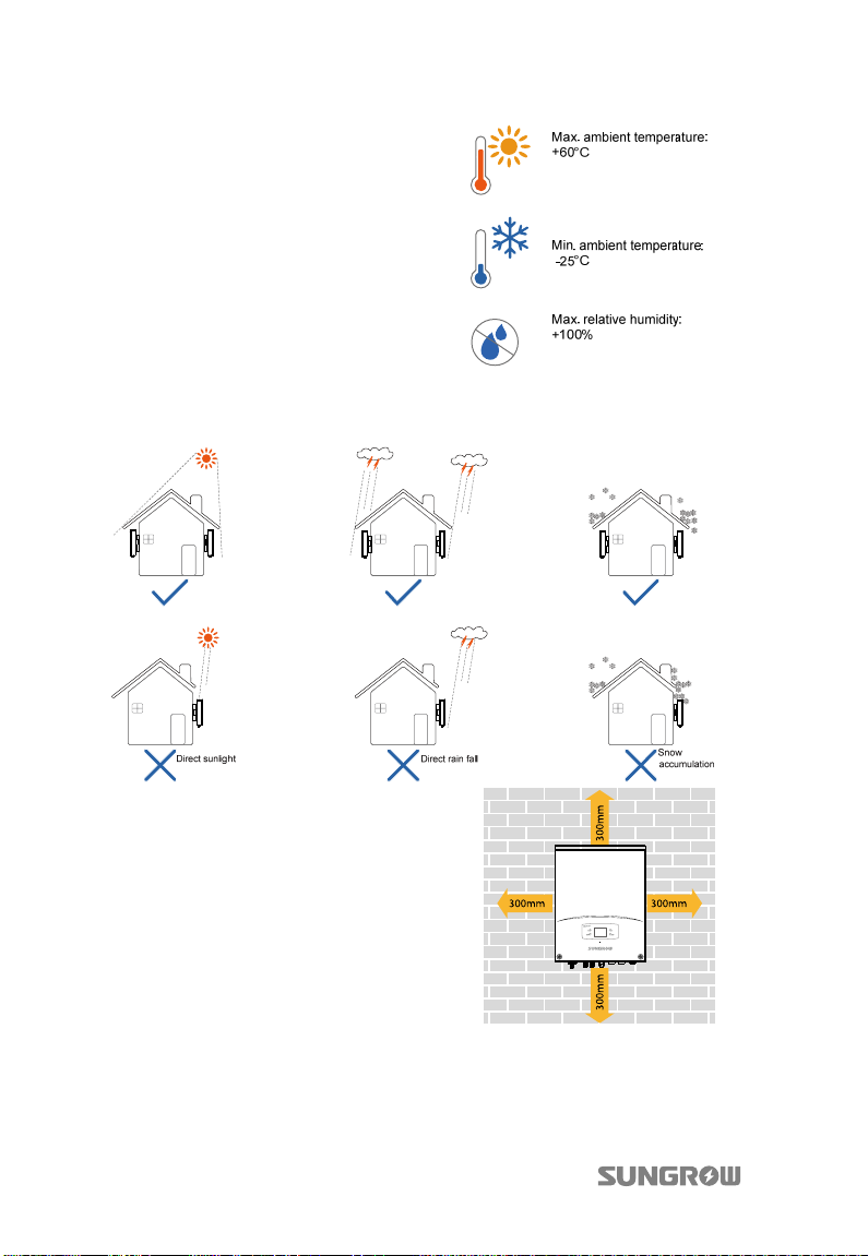
9. The ambient temperature should
range from -25°C to 60°C. The power
output will reduce when the
ambient temperature exceeds 45°C.
10. The maximum relative humidity
of chosen installation site should
never exceed 100%.
11. Avoid exposing the inverter to direct sunlight, rain or snow to extend its service
life despite of IP65 rating. Shaded site of the building would be better.
12. Take enough space for convection into
consideration during installation.
18
Page 29
User Manual 4 Securing Inverter to the Wall
13. For multiple inverters installation, position
the inverters side by side. For multi-row
inverters installation, position the inverters in a
staggered arrangement.
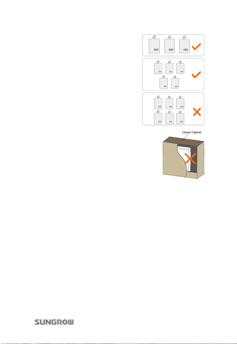
14. Do not install the inverter in a enclosed
cabinet. Otherwise, the inverter will not
operate normally.
15. Do not install inverter where children can reach.
16. Do not install the inverter in residential area. Noise can be produced during the
inverter running and may affect your daily life.
4.2 Moving Inverter to Installation Site
If the inverter is to be installed, remove the device from the packaging and move it
to the chosen installation site. During the moving process, the instructions below
should be obeyed.
1. Beware of the weight of the inverter.
2. Grasp the equipment with both hands by means of the side grips.
3. Move the inverter with the help of another person or with the lifting device.
4. Do not release the device unless it has been firmly secured to the wall.
19
Page 30
4 Securing Inverter to the Wall User Manual
4.3 Installing the Inverter
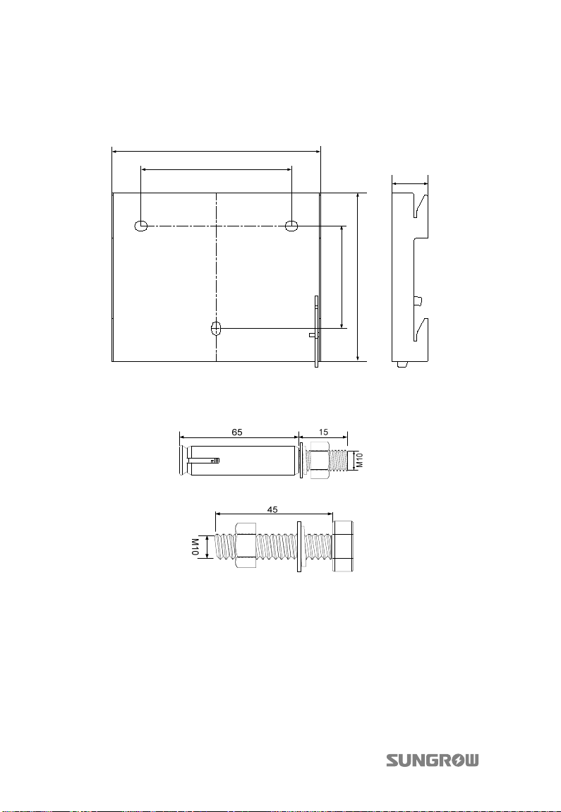
Inverter is installed onto the wall by means of wall bracket in the packaging.
277
200
46
205
125
Fig. 4-1 Dimensions of wall bracket(unit: mm)
There are two sets of stainless fasteners supplied to attach the wall bracket to the
concrete wall and metal frame respectively.
Fig. 4-2 Dimensions of Expansion Bolt Set for Concrete Wall(unit: mm)
Fig. 4-3 Dimensions of Fastener Set for Metal Frame(unit: mm)
On Concrete Wall
1. Remove the wall bracket and fasteners from the packaging.
2. Place the wall bracket onto the chosen concrete wall and adjust it until it is in
a horizontal position.
3. Mark the positions to drill holes using the wall bracket as the template.
4. Drill holes according to the marks you have made.
20
Page 31
User Manual 4 Securing Inverter to the Wall
In order to avoid electrical shock or other injury, inspect if there is electricity
or plumbing installations before drilling holes.
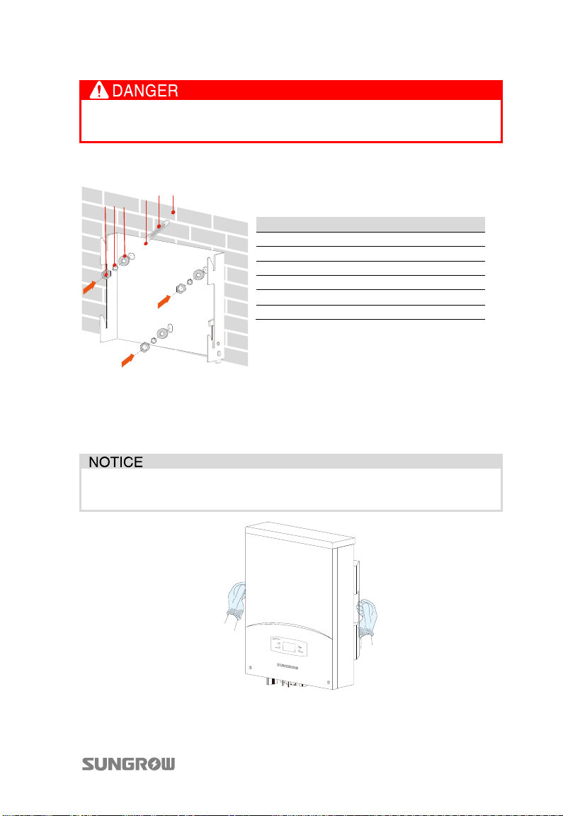
5. Attach the wall bracket to the wall with the supplied expansion bolt set. The
torque for fastening the nut should be at least 35 Nm.
1
2
3
456
No. Description
1 Concrete wall
2 Expansion cylinder (M10x80)
3 Wall bracket
4 Washer
5 Spring washer
6 Hexagonal socket nut
Fig. 4-4 Fasten the Wall bracket against Concrete Wall
6. Lift up the inverter above the wall bracket with the help of other people and
then slide down. Make sure that the grooves on the back of the inverter and
the hooks on the wall bracket engage perfectly, as shown in Fig. 4-5.
The installers must wear gloves to avoid scratches when mounting the
inverter.
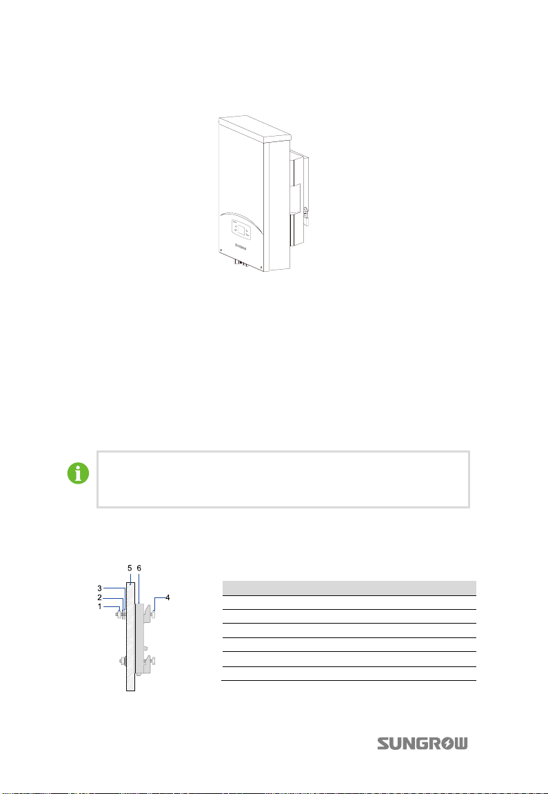
Fig. 4-5 Installing the Inverter
21
Page 32
4 Securing Inverter to the Wall User Manual
k
7. To protect the inverter from theft, you can lock it to the wall bracket with a
padlock.
On Metal Frame
If the chosen mounting location is metal frame, please proceed as follows to mount
the inverter.
1. Remove the supplied wall bracket from the packaging.
2. Choose the best installation site according to above requirements. Place the
wall bracket onto the chosen metal frame and adjust it until it is in a
horizontal position.
3. Mark the positions to drill holes by using the wall bracket as the template.
4. Drill holes at the marks you have made.
If the shape of the metal frame does not fit the holes on the wall bracket,
you need to re-drill holes on the wall bracket at appropriate position
according to the chosen frame.
5. Fasten the wall bracket against the metal frame with bolts and nuts. The
dimensions of fasteners used in the following diagram are recommended.
The torque for fastening the nut is 35 Nm.
No. Description Remar
1 Hexagonal socket nut M10
2 Spring washer -----3 Washer -----4 Hexagonal bolt M10x45
5 Metallic wall -----6 Wall bracket ------
Fig. 4-6 Fasten Wall bracket against Metal Frame
22
Page 33
User Manual 4 Securing Inverter to the Wall
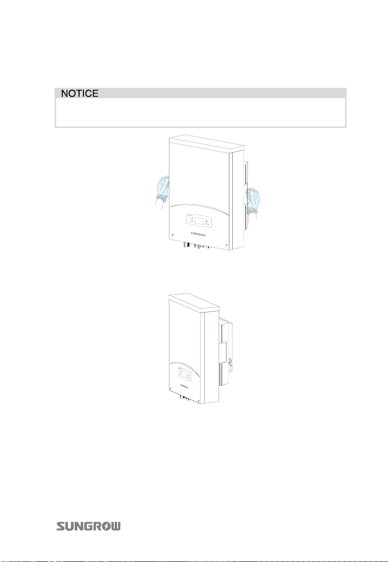
6. Lift up the inverter above the wall bracket with the help of other people and
then slide down. Make sure that the grooves on the back of the inverter and
the hooks on the wall bracket engage perfectly.
The installers must wear gloves to avoid scratches when mounting the
inverter.
Fig. 4-7 Attaching Inverter onto Wall bracket
7. To protect the inverter from theft, you can lock it to the wall bracket with a
padlock.
23
Page 34
5 Electrical Connection
Once the inverter is firmly attached to the appropriate location, it can be connected
into the PV power system.
Improper operation during the wiring process can cause fatal injury to the
operators or unrecoverable damages to the inverter.
Only qualified personnel can perform the wiring work.
Prior to any electrical connection, keep in mind that the inverter has dual power
supplies. It is mandatory for the technical personnel to wear personal protective
equipments during the electrical work: helmet, footwear and gloves.
5.1 Overview of Electrical Connection
Connecting inverter to the existing PV system includes connecting inverter to local
grid and connecting inverter to PV arrays. There may be communication connection
for monitoring if necessary.
All electrical connection should follow the National Wiring Rules of Standard AS/NZS
3000. The requirements in AS 4777.1 and AS/NZS 3000 indicate that a DC isolator
must be used before the inverter.
24
Page 35
User Manual 5 Electrical Connection
k
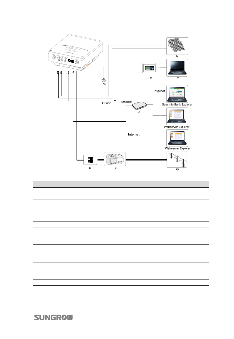
Fig. 5-1 Electrical Connection Diagram
Item Description Remar
A PV arrays The maximum open-circuit voltage of each PV string is
B SolarInfo logger
1000 V.
It can be ordered from SUNGROW. Or use
compatible logger from Meteo-Control, Solar-Log
or Papendorf SE
C Remote PC User uses this device to monitor the whole PV system.
D Router/Switch Used as data transferring device between inverter and
E AC circuit breaker Used as a protective device during electrical
F Smart energy
meter (optional)
G Utility Grid Rated AC voltage is 230 V.
the Internet/Webserver, to monitor the whole PV
system
connection. User equips this device according to the
maximum output voltage and current.
Three-phase electronic energy meter, used to measure
the active power output. Communicate with the
inverter via RS485 port.
25
Page 36
5 Electrical Connection User Manual
5.2 Terminals Description
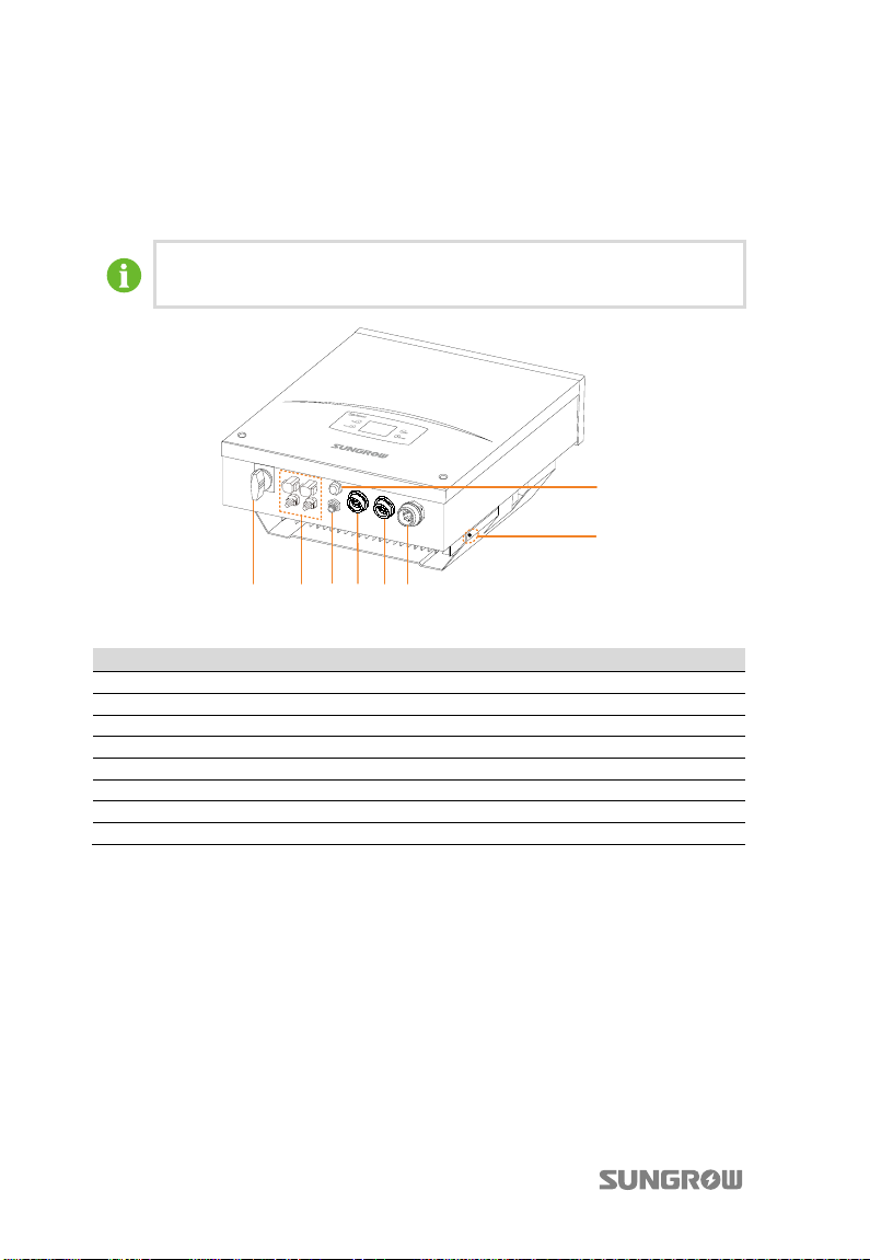
All electrical terminals are located at the bottom of the inverter. Fig. 5-2 shows the
connection area.
Enough space around the inverter should be kept for electrical
connection when choosing the installation site.
5
8
3261
74
Fig. 5-2 Terminals Description
Item Description
1 Integrated DC switch
2 DC connectors: MC4
3 AC connection terminal
4 Wi-Fi connection terminal
5 DI connection terminal
6 RS485 connection terminal
7 NET connection terminal
8 Second PE terminal
5.3 Meter Connection (optional)
The smart energy meter is installed between the air breaker and the grid. It
measures the feed-in power and communicates with the inverter through RS485
connection. This section describes the power cables connection of the meter.
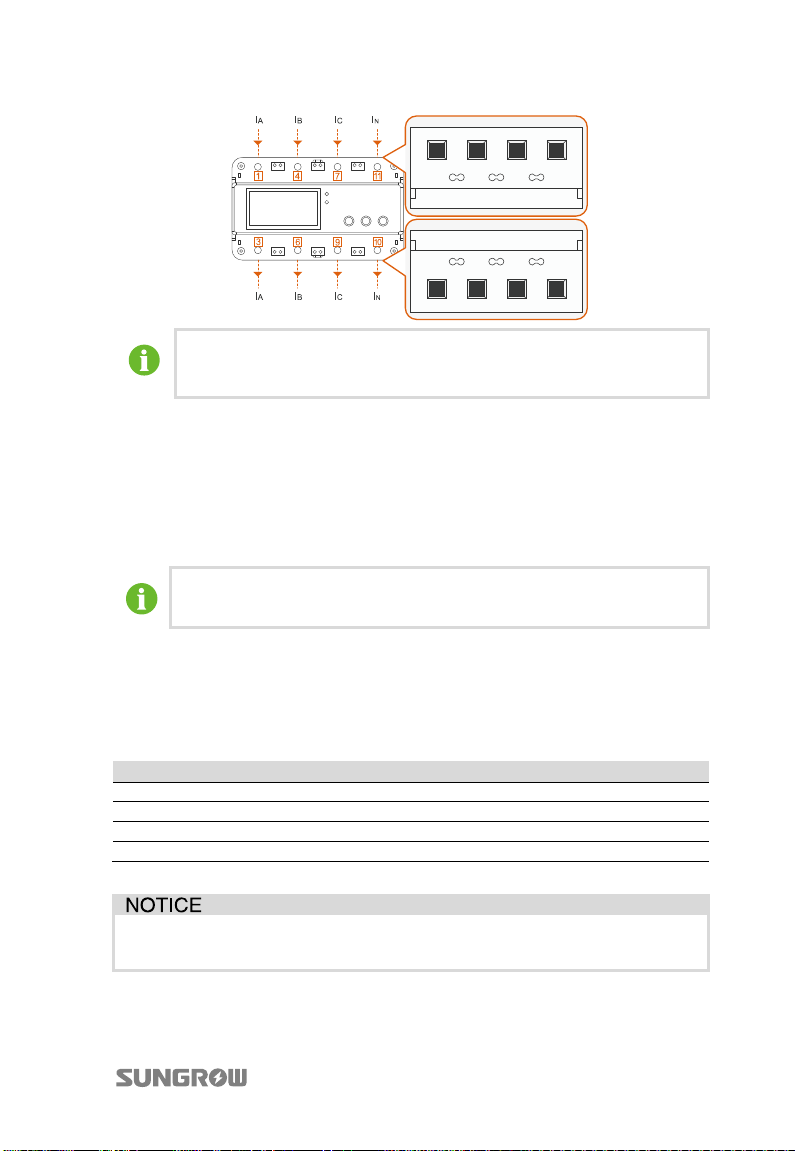
The following figure shows the cable requirements and connection.
26
Page 37
User Manual 5 Electrical Connection
The recommended cross-section area of conductor is 16 mm2.
The length of insulation to be stripped off is 10 mm~13 mm.
*Image shown here is for reference only. For the detailed information, see the user
manual of meter.
5.4 Connecting Inverter to Grid
5.4.1 AC Side Requirements
Only after receiving prior approval from the local grid company as
required, should you connect the inverter to the grid.
AC Side Circuit Breaker
An independent three or four-pole circuit breaker for the inverter must be installed
at the output side to ensure that the inverter can be securely disconnected under
load.
Inverter Type Specification for AC Circuit Breaker
SG3KTL-EC 10A
SG4KTL-EC 10A
SG5KTL-EC 16A
SG6KTL-EC 20A
It is not allowed for several inverters to use the same circuit breaker.
It is not allowed to connect loads between the inverter and circuit breaker.
27
Page 38
5 Electrical Connection User Manual
Residual Current Device
With an integrated universal current-sensitive residual current monitoring unit
inside, the inverter is able to distinguish the fault currents from normal capacitive
leakage currents. The inverter will disconnect from mains as soon as a fault current
with value exceeding the limit has been detected.
However if an external RCD or residual current breaker is mandatory, the switch
must be triggered at a failure current of 300 mA or higher.
Requirements of Multiple Inverters in Parallel Grid Connection
If several inverters are operated in parallel connection to grid, different
requirements should be obeyed (See technical information “Technical notes for
multiple-paralleled grid-connected inverters” in the download area of SUNGROW
website).
AC Cable Requirements
The grid is connected to the inverter via 5 wires (L1, L2, L3, N and PE). Feed-in power
is always three-phase via AC terminal at the bottom of the device.
Consider the following facts when selecting AC cables specifications and types:
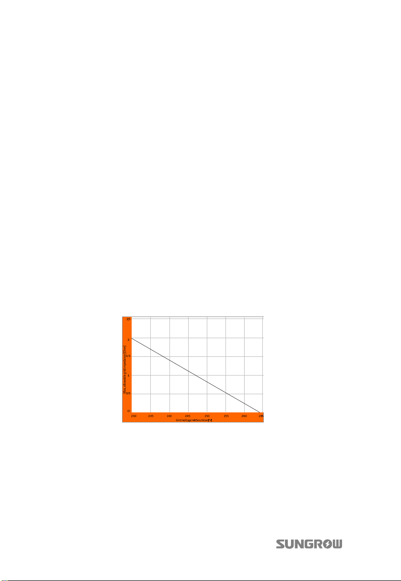
The grid impedance of the AC cables must correspond to the specification to
avoid unintended disconnection from the grid or derating of the output power.
The maximum cable length depends on the cable cross-section area, as shown in
the following table. Note that the power loss of the cables should be within 1% of
the nominal power.
28
Page 39
User Manual 5 Electrical Connection
Type Single Conductor Cross
Section
Range Recommended Range Recommended
SG3/4/5/6K
TL-EC
Withstand ambient temperature;
Layout type (inside wall, underground, free air etc.);
UV resistance and so on.
4…10
mm²(AW
G11…A
WG7)
4…10 mm²
(AWG11…AWG
7)
Total Outer cable
diameters
11…20
mm
15 mm 100 m
Maximu
m Cable
Length
5.4.2 Assembling AC Cables to Connector
The inverter is equipped with water-proof connector for AC connection, which
matches the AC terminal at the bottom of the inverter.
Danger to human life due to high voltage existing inside the inverter!
Make sure that all the AC cables to the inverter are not live before the
electrical work.
Do not turn on the AC circuit breaker until all electrical connections are
completed.
Prior to connecting to the utility grid, verify whether the grid voltage and frequency
are within the range of inverter output parameters, referred to “12 Appendix”.
Consult local grid company for solution, if otherwise.
All AC cables should be equipped with correctly colored cables for
distinguishing. Please refer to related standards about wiring color.
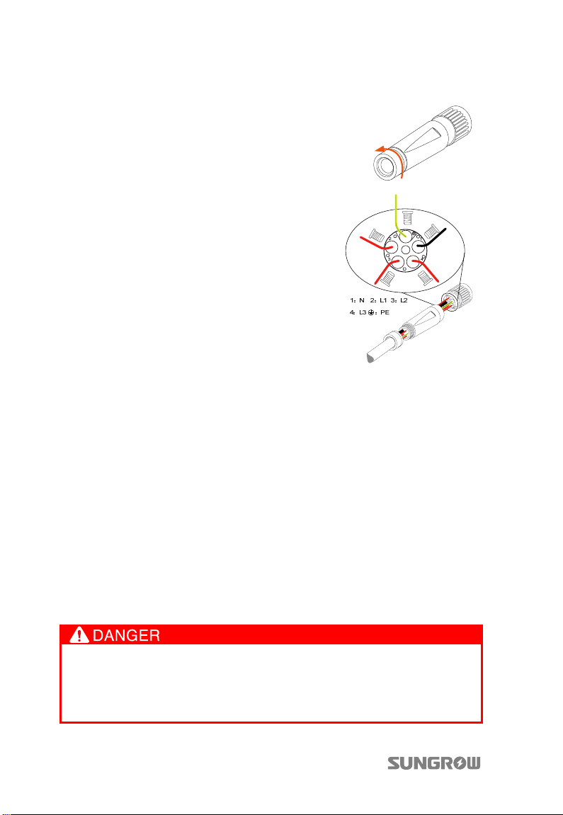
Connecting Inverter to AC Grid
Observe the terminal layout of AC connector. If a phase wire is connected to
the “PE” terminal, the inverter will not function properly.
29
Page 40
5 Electrical Connection User Manual
AC Wir ing Procedure
1. Unscrew the water-proof terminal in
the following direction.
2. Insert appropriate size AC cables into
the water-proof terminal.
3. Strip off insulation layer of all AC cables.
The length of strip insulation is
approximately 10 mm.
4. Fix all cables ends to the corresponding
terminals with the torque of 1 Nm
according to markings on the
connector, especially “PE” cable. If a
phase wire is connected to the “PE”
terminal, the inverter will not function
properly.
5. Pull cables outwards to confirm whether they are installed firmly.
6. Combine the two front-end parts together with the torque of 2 Nm.
7. Tighten the water-proof terminal with the torque of 5 Nm in opposite
direction.
8. Make sure the AC and DC circuit breakers are disconnected.
9. Connect phase cables and “N” cable to AC circuit breaker.
− Plug AC connector to corresponding AC terminal.
− Screw AC cables except the “PE” cable to the AC circuit breaker.
10. Connect AC circuit breaker to the utility grid.
11. Make sure all AC cables are firmly installed.
5.5 Connecting Inverter to PV Arrays
Lethal voltage exists!
PV arrays produce electrical energy when exposed to light and thus can
create an electrical shock hazard. Wiring should be performed only by
qualified personnel.
30
Page 41
User Manual 5 Electrical Connection
Make sure that the maximum input-ground capacity of the inverter is less
than (0.12 uf/kW) * 3 kW/4 kW/5 kW/6 kW, otherwise the inverter will not
function properly.
Before connecting the PV arrays to the inverter, make sure that the
impedances between the positive terminal of the PV string and Earth and
the impedances between the negative terminal of the PV string and Earth
are larger than 200 Kohm.
There is a risk of inverter damage! The following requirements should be met,
otherwise they will lead to loss of any and all warranty rights.
Make sure that the maximum short circuit current of each DC input is less than
inverter allowable limit.
Make sure that the maximum open voltage of each string is less than 1000 V.
Voltage over 1000 V can damage the inverter.
If the input line is changed, such as input line falls off, panels
configuration modified, etc. You need to reset the work mode.
5.5.1 PV Inputs Configuration
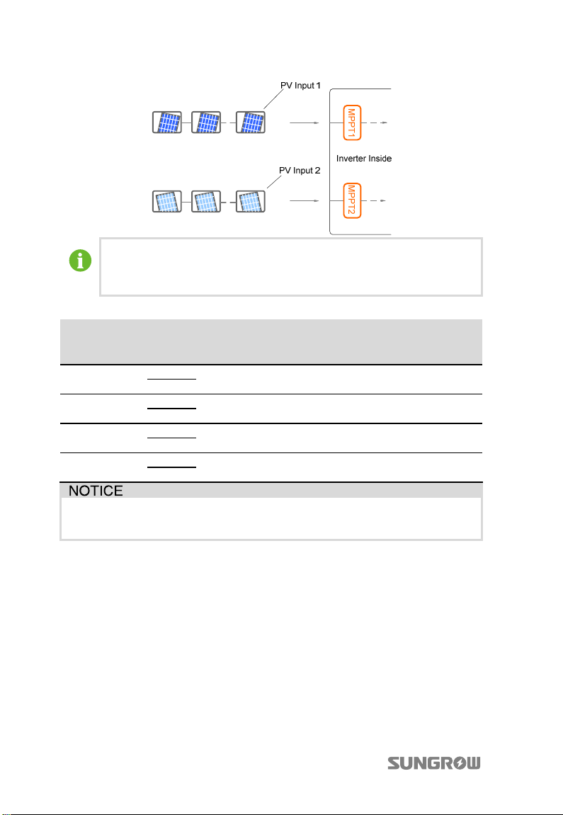
The inverter has two PV input areas DC1 input and DC2 input, each with its MPP
tracker. The two PV inputs can be configured in independent mode or parallel mode.
PV Configuration Mode-Independent Mode
For independent mode, the two PV inputs work independently, each with its own
MPPT. Therefore the two PV inputs can be different from each other in PV module
types, numbers of PV panels in PV strings, tilt angles and orientation angles of PV
modules.
As shown in the following figure, the inverter should be configured to independent
mode due to different orientation angles between the two PV inputs.
31
Page 42
5 Electrical Connection User Manual
To make sure the maximum DC power, PV strings connected to individual
input area should have a homogenous structure, i.e. the same type, the
same number, the same identical tilt and identical orientation.
Prior to connecting inverter to PV inputs, the following specifications should be met:
Type Area
SG3KTL-EC
SG4KTL-EC
SG5KTL-EC
SG6KTL-EC
DC1
DC2
DC1
DC2
DC1
DC2
DC1
DC2
DC Power
Limit for
Each Input
3191 W 1000 V 12.4 A
4255 W 1000 V 12.4 A
5265 W 1000 V 12.4 A
6312 W 1000 V 12.4 A
Open-circuit
Voltage Limit
for Each Input
Short-circuit
Current Limit
for Each Input
In independent mode, when there is only one PV input, the other input may
produce induced voltage. DO NOT touch the unused DC terminals.
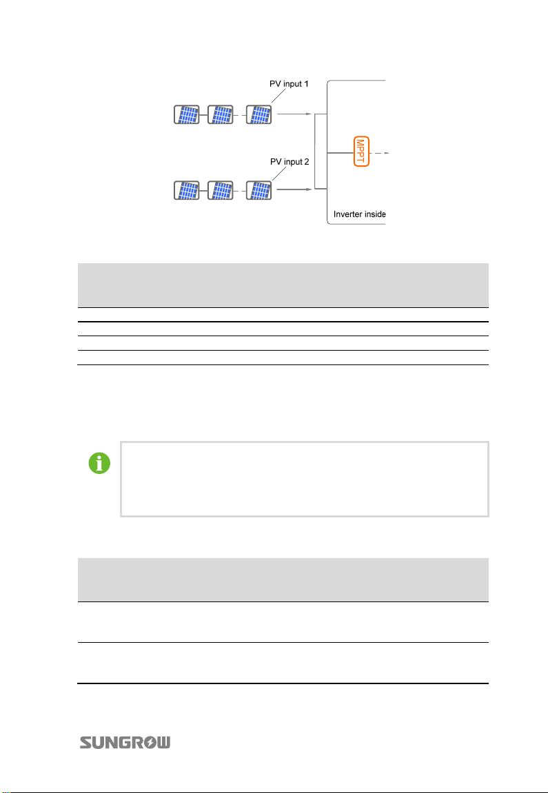
PV Configuration Mode-Parallel Mode
For parallel mode, all PV strings with the same type, the same number of PV panels,
identical tilt and identical orientation in series can be connected to the same single
input area. Two trackers are configured in parallel to handle power and/or current
levels higher than those a single tracker can handle.
As shown in the following figure, the inverter may choose parallel mode since there
is no difference between the two PV inputs. The terminals in DC1 input and DC2
input must be short-circuited by Y-type cable connector.
32
Page 43
User Manual 5 Electrical Connection
Prior to connecting the inverter to PV inputs, the following electrical specifications
must be met simultaneously:
Type
SG3KTL-EC 3191 W 1000 V 24.8 A
SG4KTL-EC 4255 W 1000 V 24.8 A
SG5KTL-EC 5265 W 1000 V 24.8 A
SG6KTL-EC 6312 W 1000 V 24.8 A
Total DC Power
Limit for Inverter
Open-circuit
Voltage Limit for
Each Input
Short-circuit
Current Limit for
Total Input
5.5.2 Assembling DC Cable to Connector
All DC cables are equipped with water-proof direct plug-in connectors, which match
the DC terminals at the bottom of the inverter.
The positive and negative connectors are marked with polarity symbols
and should be equipped with correctly colored cables.
e.g. Red cable should be connected with DC positive terminal while the
blue one should be connected with the negative.
DC Cable Requirements
Type Cross-Section
Area Range
2
SG3KTL-EC
SG4KTL-EC
4...6 mm
12AWG-10AWG
2
4...6 mm
12AWG-10AWG
Outer Cable
Diameters
Max.
Withstand
Voltage
6…9 mm 1000 V
6…9 mm 1000 V
Max.
Withstand
Current
Same with
short-circuit
current.
Same with
short-circuit
current.
33
Page 44
5 Electrical Connection User Manual
f
Type Cross-Section
Area Range
2
SG5KTL-EC
SG6KTL-EC
4...6 mm
12AWG-10AWG
2
4...6 mm
12AWG-10AWG
Outer Cable
Diameters
Max.
Withstand
Voltage
6…9 mm 1000 V
6…9 mm 1000 V
Max.
Withstand
Current
Same with
short-circuit
current.
Same with
short-circuit
current.
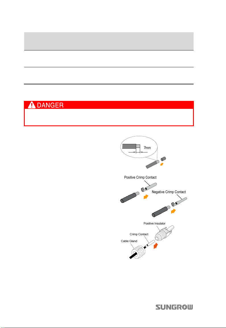
DC Connector Assembling Procedure
Make sure that all the DC and AC cables to the inverter are not live before
the electrical work.
1. Strip of
7 mm insulation layer from
all DC cables.
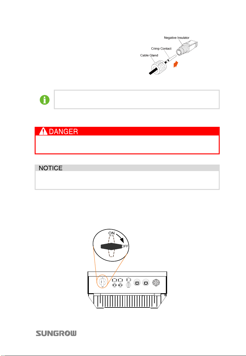
2. Assemble cable ends with crimp
contacts by crimping pliers.
3. Lead cable through the cable gland.
4. Insert the crimp contact into the
insulator until it snaps into place.
Then pull gently to check if it is
correctly engaged.
5. Screw the cable gland to front
insulator with tightening torque
2.5…3 Nm.
34
Page 45
User Manual 5 Electrical Connection
For further assembly and connection instruction, please visit the
webpage of the device manufacturer.
5.5.3 DC Wiring Procedure
Make sure that none of the DC or AC cables connected to the inverter is live
before the electrical work.
Make sure that the open circuit voltage does not exceed inverter input limit
of 1000 V, even under the lowest operating temperature.
PV Connection of Independent Mode
Connect the inverter to PV arrays according to the following procedures:
1. Rotate the DC switch at the bottom to the “OFF” position.
35
Page 46
5 Electrical Connection User Manual
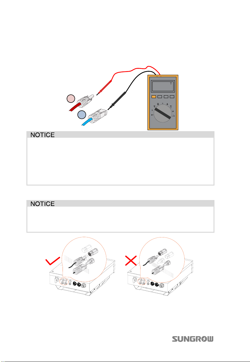
2. Check the cable connection of PV strings for the correct polarity and that the
open-circuit voltage does not exceed the inverter input limit 1000 V, even
under the lowest operating temperature. Refer to module specification
supplied by module manufacturer for detailed information.
480.0
+
-
The inverter will not function properly if the DC polarities are reversed.
Check the positive and negative polarity of the PV cells. After confirmation,
you can insert the DC connectors into the input terminals on the bottom of the
inverter.
For the same MPPT, reverse connection of a single string is prohibited. A
permanent failure of the system or inverter may follow if otherwise.
3. Plug the positive and negative DC connectors into corresponding terminals
until there is an audible click.
Connect the same PV string to terminals of the same input areas. For
example, connect the positive pole of a string to DC1 input and the negative
pole to the DC1.
* Image shown here is for reference only. Actual product you receive may differ.
4. Connect other PV strings as the same procedures if necessary. Seal unused
DC terminals with the terminal caps.
36
Page 47
User Manual 5 Electrical Connection
PV Connection of Parallel Mode
Connect the inverter to PV arrays according to the following procedures:
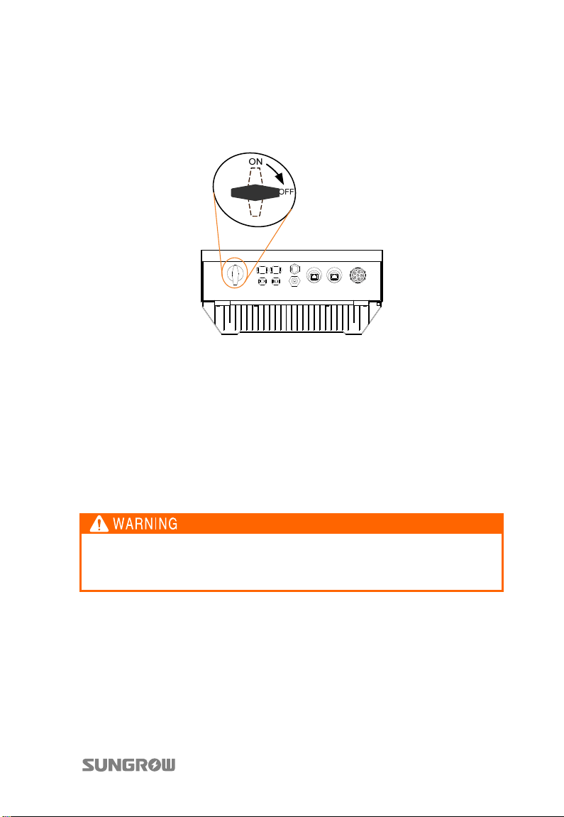
1. Rotate the DC switch at the bottom to the “OFF” position.
2. Check the cable connection of PV strings for the correct polarity and that the
open-circuit voltage does not exceed the inverter input limit 1000 V.
3. Plug the positive and negative DC connectors into corresponding terminals
until it click-locks into place.
4. The terminals in DC1 input and DC2 input must be short-circuited by Y-type
cable connector.
5. Connect other PV strings in the same procedures if necessary.
5.6 Grounding the Inverter
Because of the transform-less design of the inverter, DC positive pole and
DC negative pole are not permitted to be grounded. Otherwise the inverter
will not function properly.
5.6.1 Grounding System Overview
All non-current carrying exposed metal parts of the equipment and other
enclosures in the PV power system should be grounded (e.g., PV arrays frame and
inverter enclosure).
37
Page 48
5 Electrical Connection User Manual
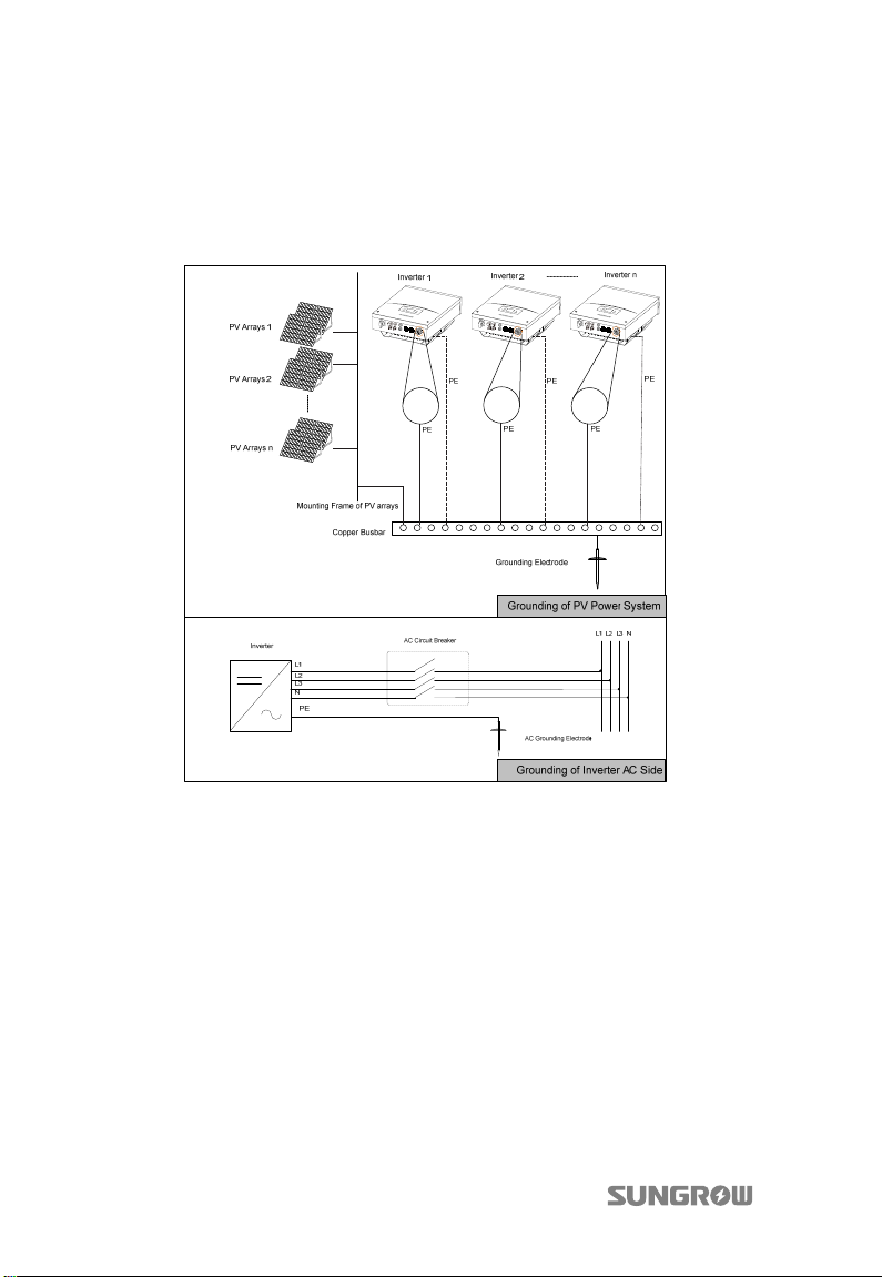
Where there is only one inverter in the PV power system, connect the “PE” cable to
the installation ground.
Where there are multiple inverters in the PV power system, connect the “PE” cables
of all inverters and mounting frame of PV arrays to the same copper bus bar. In this
way, they are in equipotential connection.
Fig. 5-3 Grounding of Inverter
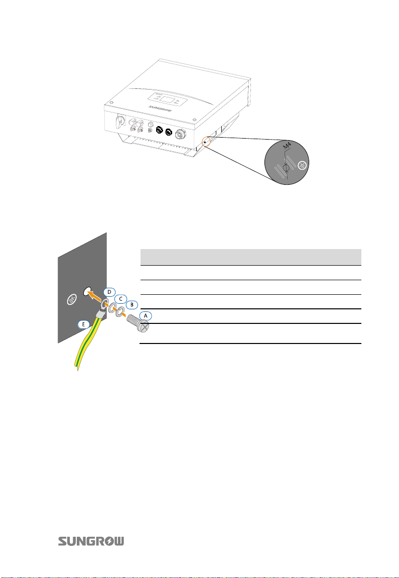
5.6.2 Second Protective Earth Terminal
The inverters are equipped with second protective earth terminal as specified in EN
50178.
Second PE Terminal
There is a PE terminal on the right side of the inverter. You may choose to connect
the PE.
38
Page 49
User Manual 5 Electrical Connection
Fig. 5-4 Second PE Terminal
Second PE Connection
Item Description Specification
A Screw
B Spring washer -
C Washer D Cable socket -
E Yellow-green cable
M4×12 mm
2
-10 mm2 copper wire or
6 mm
2
10 mm
-16 mm2 aluminum wire
Fig. 5-5 Connection of the Second PE Connection
5.7 Communication Connection
5.7.1 Interfaces Overview
All communication terminals are located on the bottom of the inverter.
There are three optional connection ports on the bottom of the inverter: RS485
serial communication with RJ45 port (RS485), Ethernet communication with RJ45
port (NET) and Wi-Fi connection terminal.
39
Page 50
5 Electrical Connection User Manual
For RS485 serial communication, the inverter operation information can be
transferred via RS485 port to a PC with monitoring software, or to data logging
device (such as MC Logger). The inverter operation information can also be
transferred via Wi-Fi terminal to a PC with monitoring software, or to SolarInfo
Bank via the router.
For Ethernet communication, the inverter operation information can be
transferred via NET port to a PC with monitoring software, or to Webserver, or to
SolarInfo Bank via the router.
Before communication connection, prepare communication cables and RJ45 plugs.
Cable requirements to ensure quality of communication:
Shielded network cable
DI connection cable
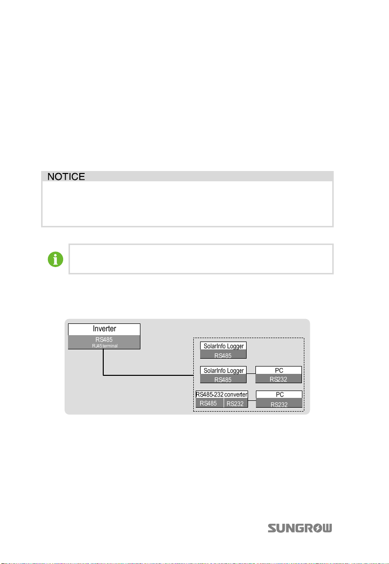
A converter such as RS485-232 converter or SolarInfo Logger, which
converts 485 signal to 232 signal, is needed between the inverter and PC.
5.7.2 RS485 Communication Connection
A RS485 cable can guarantee the communication connection.
Fig. 5-6 Inverters RS485 communication connection
40
Page 51
User Manual 5 Electrical Connection
If the communication system is equipped with SolarInfo Logger, inverters
may be remotely monitored via SolarInfo Bank.
SolarInfo logger and RS485-232 converter are optional parts and can be
ordered from SUNGROW.
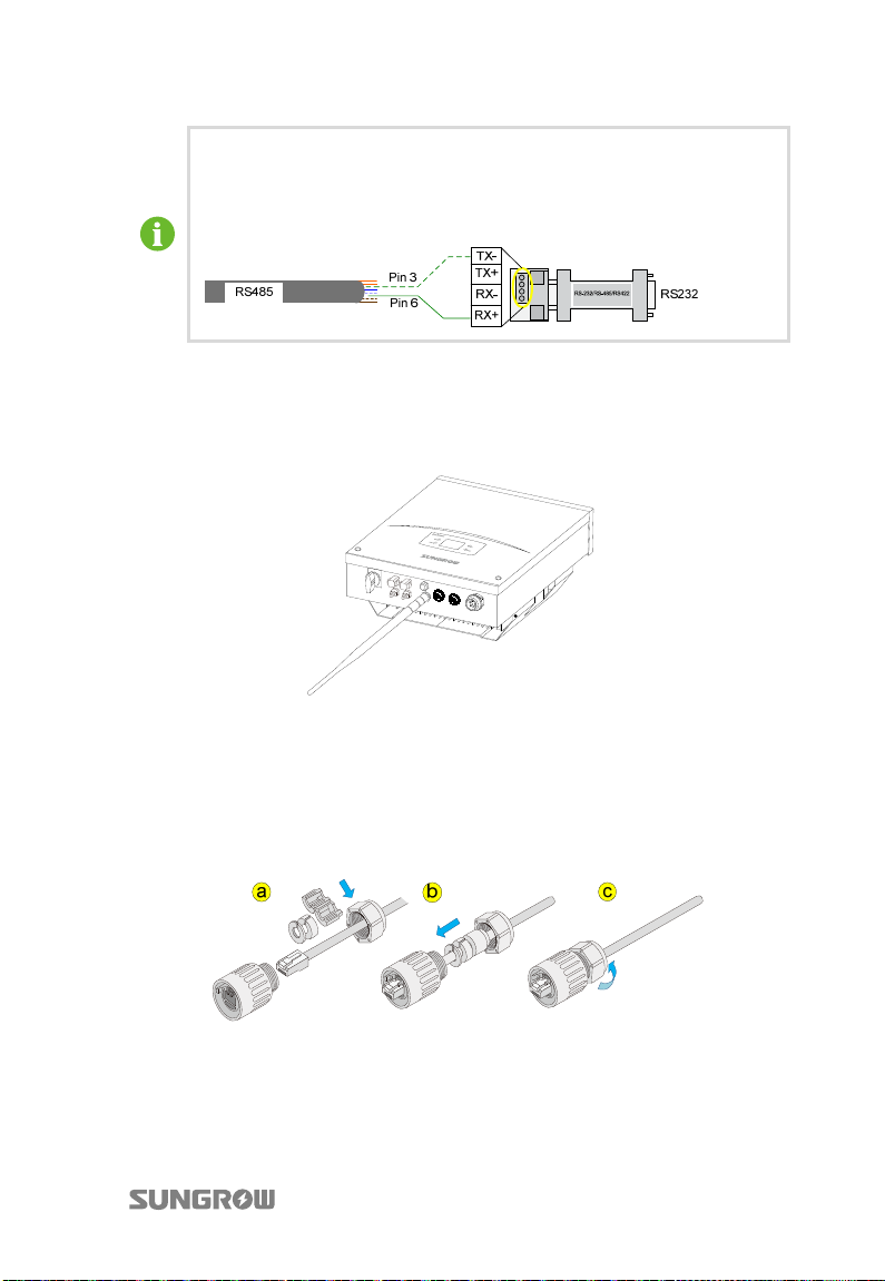
Wi-Fi Connection Procedure
1. Unscrew the waterproof lid from the Wi-Fi terminal.
2. Screw the Wi-Fi antenna to Wi-Fi terminal with appropriate torque.
RS485 Connection Procedure
1. Remove the waterproof lid from the RS485 port.
2. Insert the RJ45 plug into the front plug connector until it makes a clicking
sound. Install the plastic rings then tighten the cable gland with appropriate
torque.
3. Pull cable outwards to confirm whether it is fastened firmly.
4. Plug the other end of network cable into the socket of the switch or router,
then connect the switch or router to a PC.
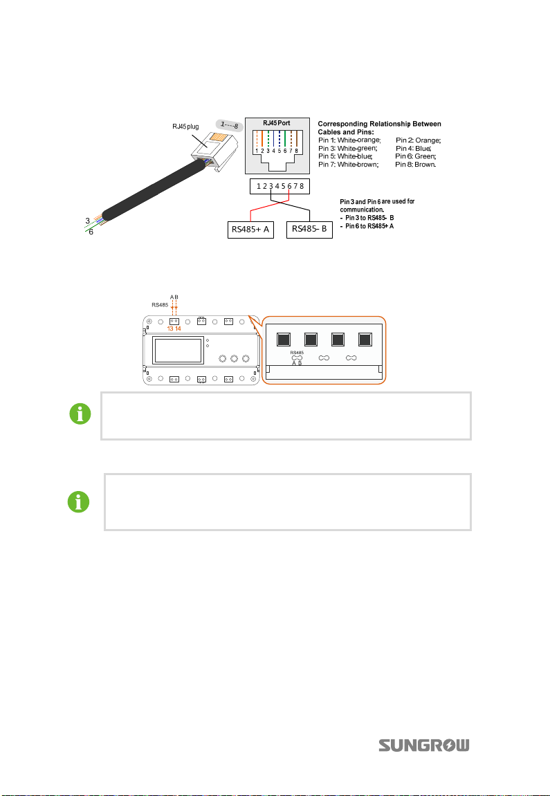
5. As for the wires which connect to the terminating resistor or logging devices,
use a Network cable crimping plier to strip the insulation layer and connect
41
Page 52
5 Electrical Connection User Manual
the RS485 A and B cables (3 and 6) to terminating resistor or data logging
device or RS 485-232 converter.
6. Connect the other devices. Refer to the device manual for the definition of
the communication port. The following figure shows the RS485 connection
to the three-phase smart energy meter.
The length of insulation to be stripped off is 5 mm~7 mm.
The wires 3 and 6 are connected to terminals A and B respectively.
7. Verify the communication connection and configure the communication
parameters.
If there is more than one inverter to communicate with a PC or a data
logger, it is crucial to configure the communication parameters of each
inverter. See “10.9.5 Setting Communication Parameters”.
5.7.3 Ethernet Communication Connection
You can connect the inverter to PC through NET port to set up Ethernet
communication. Network cable with RJ45 plugs enables connection between the
inverter and PC.
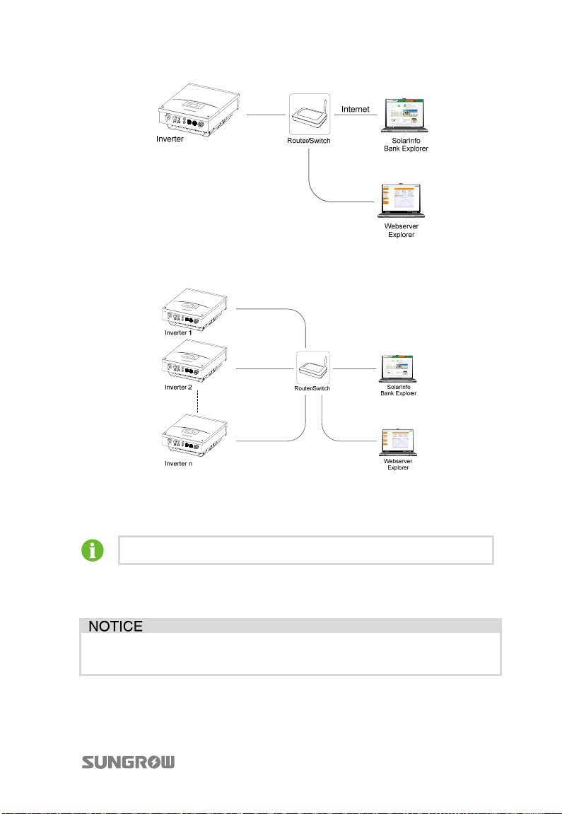
The Ethernet communication can be connected either in single or star topology.
42
Page 53
User Manual 5 Electrical Connection
Fig. 5-7 Single inverter Ethernet connection
The Ethernet communication of the daisy chain is done via external router or switch.
Fig. 5-8 Inverters Ethernet connection in star topology
The maximum number of inverters connected depends on switch, router and other
factors. Please refer to switch’s or router’s manual to obtain the limit.
The Network cable should be less than 100 m.
By logging into the Webserver explorer you can view and set the operation
parameters of a single inverter. Please refer to “6 Visiting and Configuring the
Web serv er” for detailed operation of the Webserver.
The related parameters settings can be changed only by qualified
personnel!
43
Page 54
5 Electrical Connection User Manual
Ethernet Connection Procedure
1. Remove the waterproof lid from the NET port.
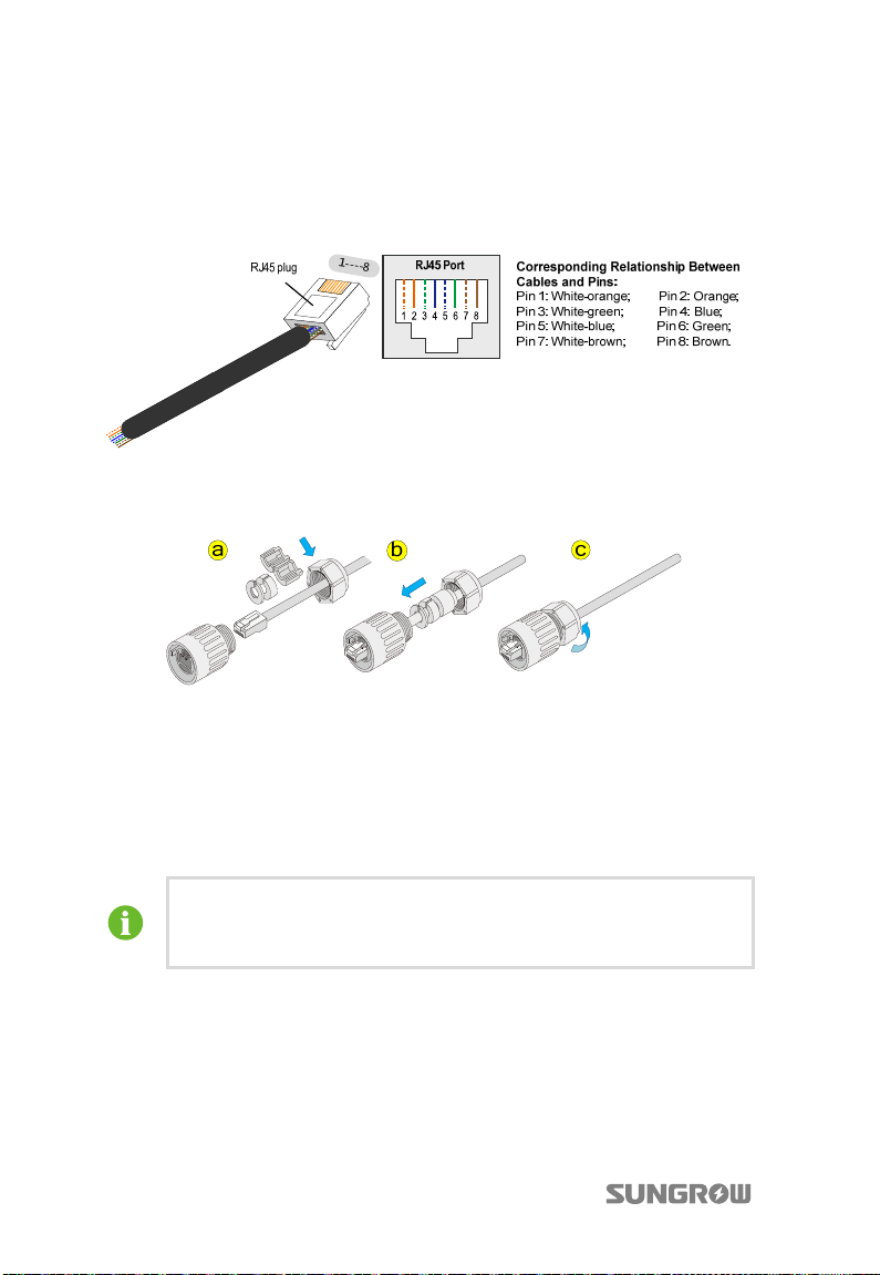
2. Use the Ethernet crimper to crimp the cable and connect the cable to RJ45
plug according to TIA/EIA 568B.
3. Insert the RJ45 plug into the front plug connector until it makes a clicking
sound. Install the plastic rings then tighten the cable gland with appropriate
torque.
4. Repeat step 1 to step 3 to connect the other inverters with Network cables.
5. Pull cables outwards to confirm whether they are fastened firmly.
6. Plug the other end of network cable into the sockets of the switch or router,
connect the switch or router to a PC. Refer to the device manual for the
definition of the communication port.
7. Verify the communication connection and configure the communication
parameters.
If there is more than one inverter to communicate with a PC, it is crucial
to configure the communication parameters of each inverter. See
“10.9.5 Setting Communication Parameters”.
44
Page 55
User Manual 5 Electrical Connection
5.7.4 Power Control Configuration
There is a terminal (DI) located on the bottom of the inverter for power control
configuration.
Prior to DI connection, please prepare additional required materials:
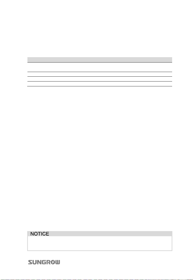
Item Type Description
1 DI connection cable
2 Stripping plier -3 Six-pole plug Contained in the delivery.
4 Screwdriver --
Power Control Settings
The inputs of DI can be used to connect a ripple control receiver for active power
control, it set as active power control by default. Please refer to “6.6 Power Control
Configuration” for DI programming.
Each state has seven functions to choose from, different statues of four digital inputs
are the configuration functions of corresponding actions:
Active power limitation setting (0-100%)
Reactive power ratio setting (0-100%)
Power factor setting (0.800-1.000)
Start
Stop
Active power limitation and reactive power ratio setting
Active power limitation and power factor setting
Where there is only one inverter, users can perform default active power limitation
function by connecting the inverter to the ripple control receiver.
Where there are several inverters, set the inverter directly connected to the ripple
control receiver via Webserver as the master inverter (communication role). Select
proper communication interface in Webserver according to the communication
cables among the inverters.
Default function configuration of DI is active power limitation: 0%, 30%, 60%, 100%.
To change this setting, please login the Webserver.
DI: 5 cores cable
Total diameter: 4…8 mm
The abovementioned settings are needed only during inverter initialization
or after the load default operation.
45
Page 56
5 Electrical Connection User Manual
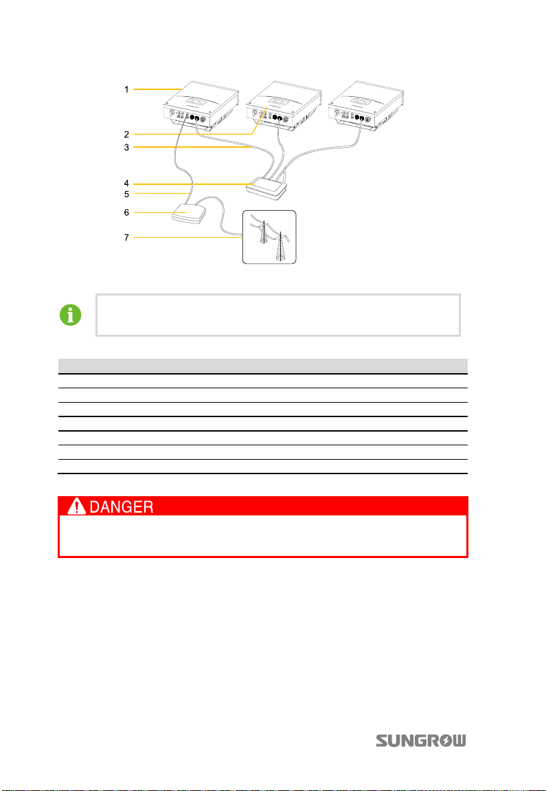
Fig. 5-9 Connecting the ripple control receiver for inverters with Ethernet connections
In the Ethernet communication connection, only one inverter can be
set as master inverter, others shall be set as slave inverters.
Item Description
1 Master inverter
2 Slave inverter
3 Ethernet cable
4 Router
5 5-conductor connection at digital input
6 Ripple control receiver
7 Grid
Connect the cables to DI terminal block according to the terminal assignment.
Make sure that all DC or AC cables connected to the inverter are not live
before the electrical work.
1. Remove the waterproof lid from DI cable gland and loosen the Thread-Lock
Sealing Nut.
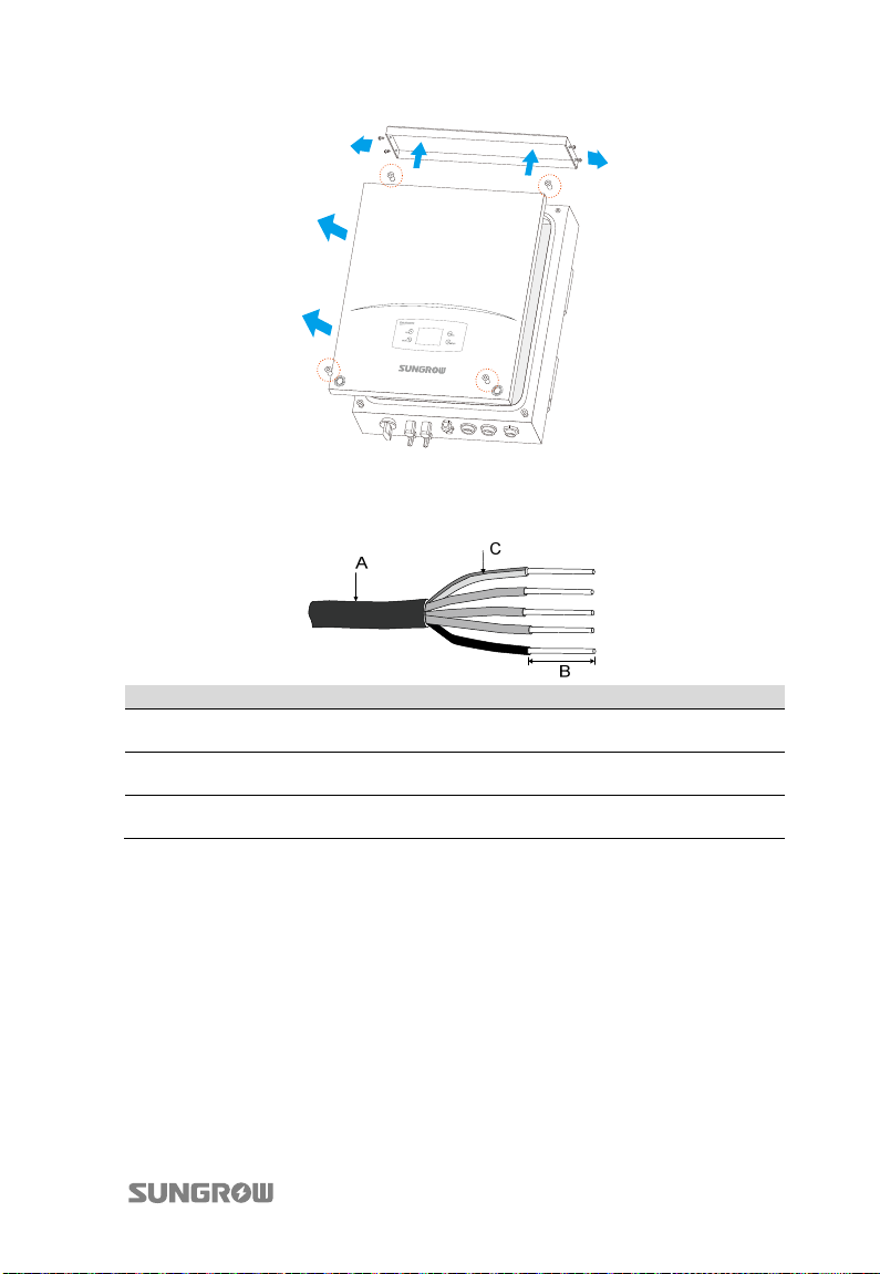
2. Loosen all screws on the top cap and remove the top cap of the inverter, then
loosen all screws on the lid and remove the lid.
46
Page 57
User Manual 5 Electrical Connection
k
3. Lead the DI connection cables through the Thread-Lock Sealing Nut and the
cable gland.
4. Strip off the DI cables as shown below.
No. Description Remar
A Protective layer
Length of insulation to be
B
stripped off
Length of protective layer
C
to be stripped off
Accepted cable external diameter ranges from
4 mm to 8 mm.
7 mm
60 mm
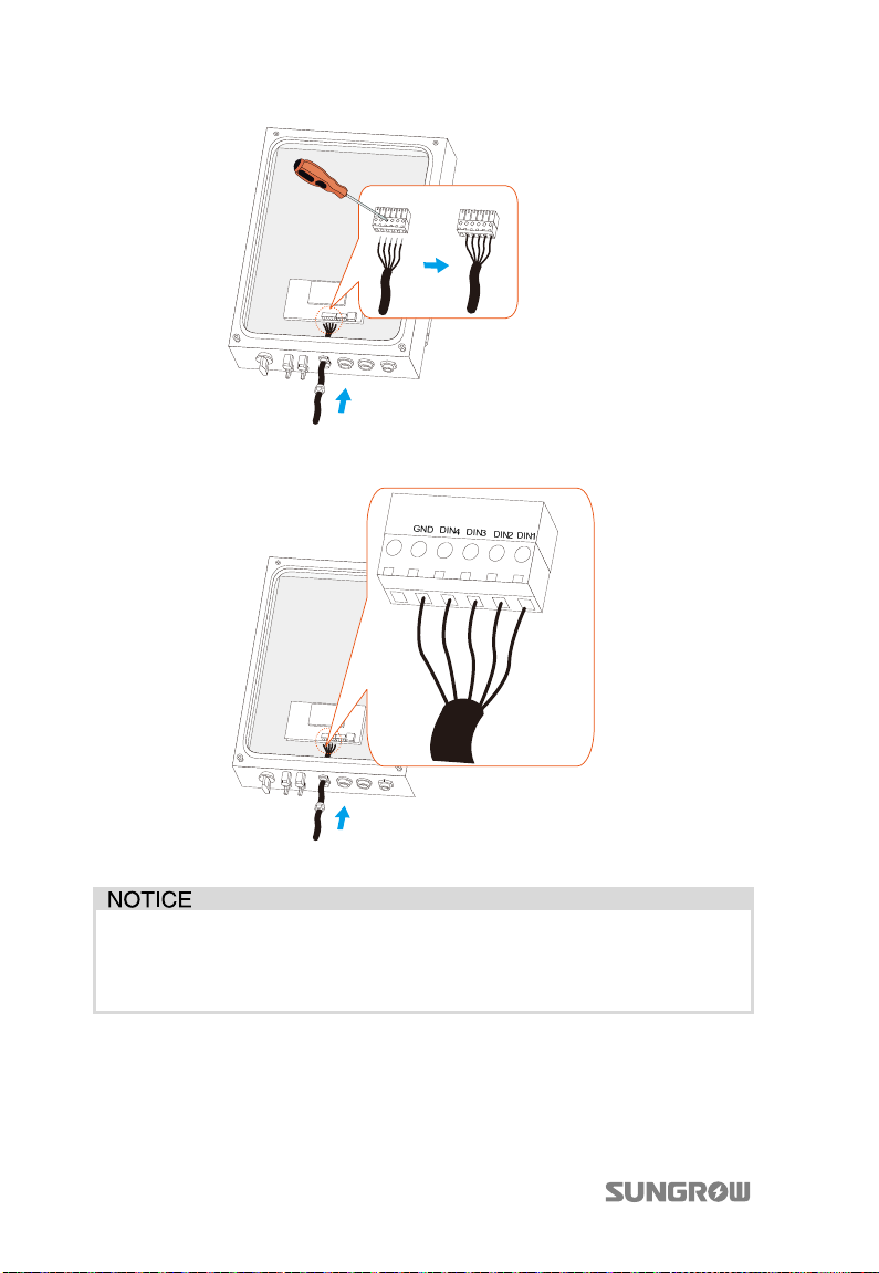
5. Assemble the individual insulated conductor into corresponding pin of the
six-pole plug with a suitable screwdriver and pull cables outwards to confirm
whether they are installed firmly.
47
Page 58
5 Electrical Connection User Manual
6. Insert the six-pole plug into the DI connection socket according to markings
shown below.
7. Fasten the Thread-Lock Sealing Nut to the inverter.
Before fasten the lid, please make sure:
Whether it’s necessary to apply glue on the cut;
The rubber strip is fully filled with air.
8. Fasten the lid and the top cap to the inverter.
9. Connect the ripple control receiver to the inverter according to the terminal
assignment.
48
Page 59
6 Visiting and Configuring the
Webserver
6.1 User and Authority
The Webserver provides user permission and installer permission. To avoid two or
more persons to change the inverter configurations at the same time, only one
person can login to Webserver at a time.
Therefore, once a person logs in and does not exit, other person cannot log in
anywhere else. Close the webpage when logging out. After logging out, it will take
at most 4s until the user log in again.
6.2 Login Interface
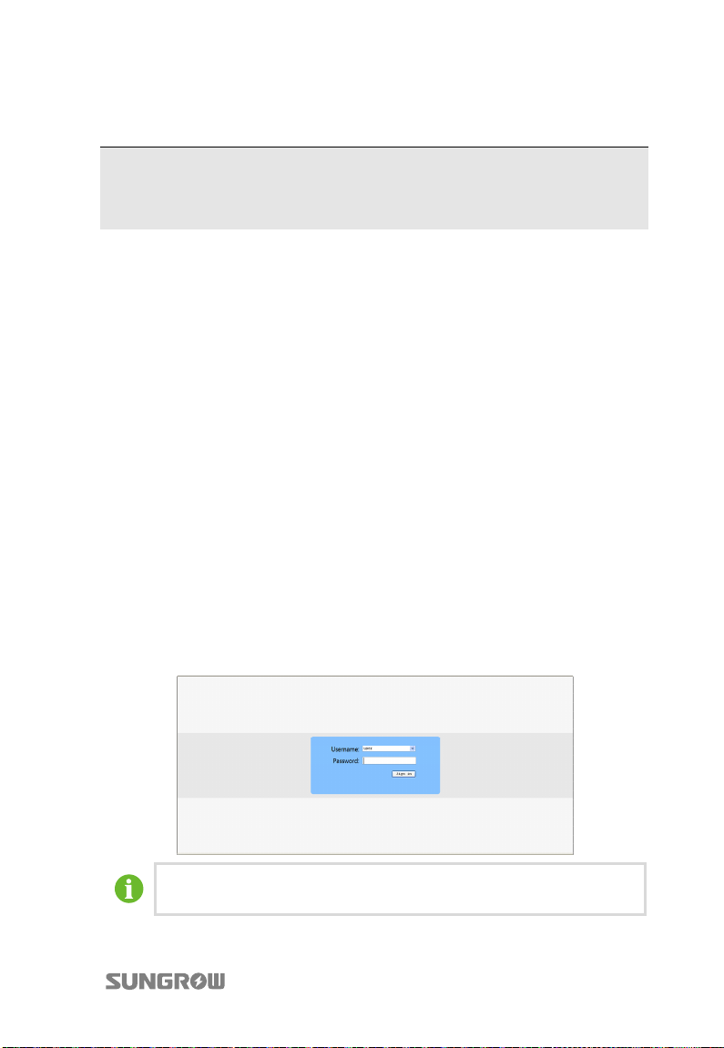
Query the inverter IP address corresponding to the instructions in “10.9.5 Setting
Communication Parameters”.
Open the browser and input the inverter’s IP address.
User should select username user after signing in with the default sign in password
of 1111. User can change the password after signing in.
After inputting the username and password, press “Sign in” or “Enter” to log in.
If there is no operation for 10 minutes, system will automatically return to
the login interface.
49
Page 60
6 Visiting and Configuring the Webserver User Manual
6.3 Main Interface
1
2
3
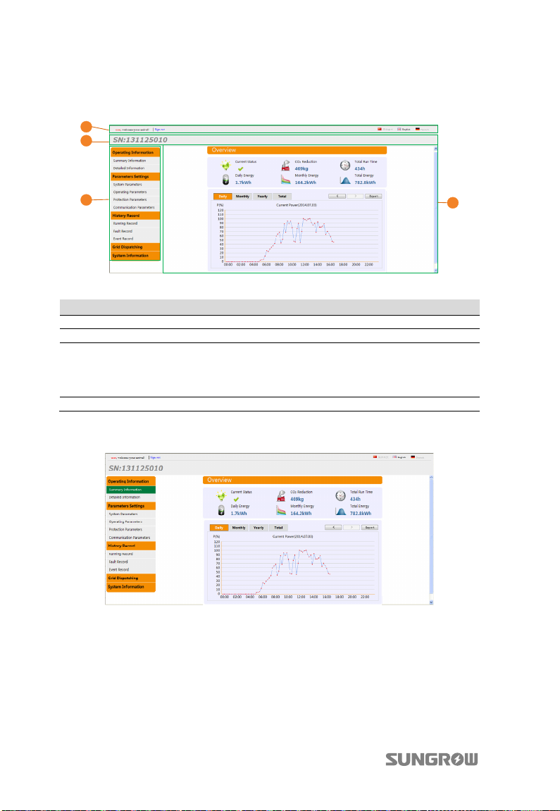
Fig. 6-1 Webserver-user interface
4
No. Name Description
1 Status bar Language selection and user login information.
2 Device info The serial number of the running inverter.
Operation information, parameter setting, history
3 Navigation bar
record, grid dispatching, system information, in which,
parameter setting and history record have their second
level menus.
4 Display area Detailed information of the selected navigation bar.
6.3.1 Summary Information
The default interface after login displays the read-only information: current status,
reduction, total run time, daily energy, monthly energy, total energy, daily
CO
2
power curve, monthly energy histogram, yearly energy histogram, and total energy
histogram. You can use the “Export” button to export data as a csv file.
50
Page 61
User Manual 6 Visiting and Configuring the Webserver
Tab. 6-1 Explanation of the icons
Icon Name Description
: Inverter is not in the fault state;
Current status
reduction CO2 reduction due to the use of inverter
CO
2
Total runtime Inverter total running time
Daily energy Energy yields of the present day
Monthly
energy
Total energy
: The inverter is in fault state. (DSP and LCD
communication fault, and the fault of the inverter.)
Energy yields of the present month
Total energy yields since the inverter connects to the
grid
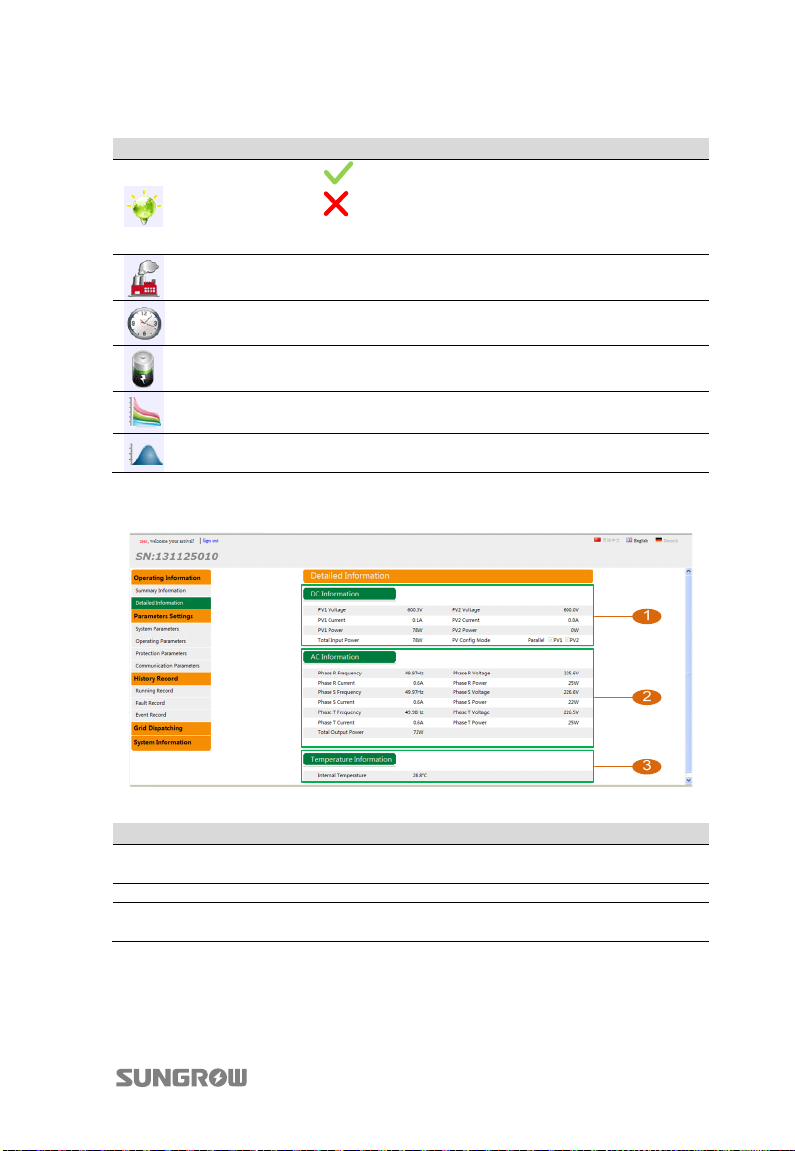
6.3.2 Detailed Information
The detailed read-only information is shown below:
No. Name Description
1 DC information
2 AC information AC side information
3
Temperature
information
51
PV1 and PV2 voltage, PV1 and PV2 current, and total
input power and so on.
Inverter internal temperature
Page 62
6 Visiting and Configuring the Webserver User Manual
6.4 Parameter Settings
Parameter settings include system parameters, operating parameters, protection
parameters, and communication parameters.
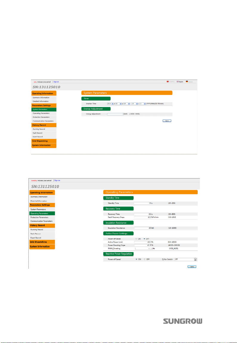
6.4.1 System Parameters
This interface is to set time and energy adjustment.
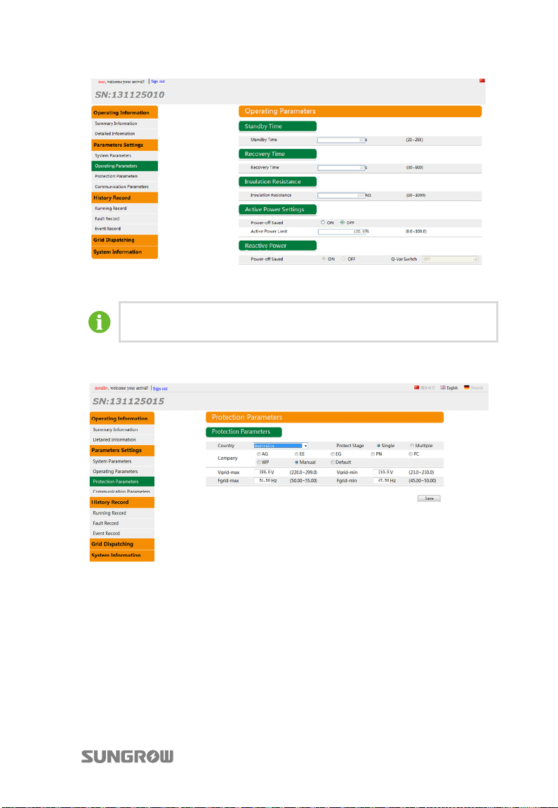
6.4.2 Operating Parameters
This interface is for Austria and Vorarlberg to set the standby time, recovery time,
insulation resistance, active power settings, and reactive power regulation.
52
Page 63
User Manual 6 Visiting and Configuring the Webserver
T
This interface is for Germany and others to set the standby time, recovery time,
insulation resistance, active power settings, and reactive power regulation.
o set the Q(P) or Q(U) parameters, please contact SUNGROW to get the
installer authority first.
6.4.3 Protection Parameters
This interface is for Australia to select the country, company, single protect stage or
multiple protect stage.
53
Page 64
6 Visiting and Configuring the Webserver User Manual
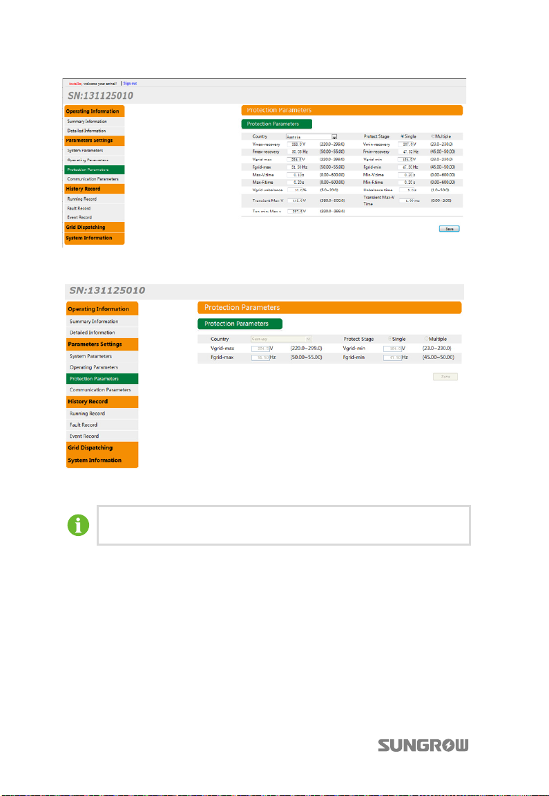
T
This interface is for Austria and Vorarlberg to select the grid codes, such as voltage,
country, single protect stage or multiple protect stage.
This interface is for Germany and others to select the grid codes, such as voltage,
country, single protect stage or multiple protect stage.
o set protection parameters mentioned above, please contact
SUNGROW to get the installer authority first.
54
Page 65
User Manual 6 Visiting and Configuring the Webserver
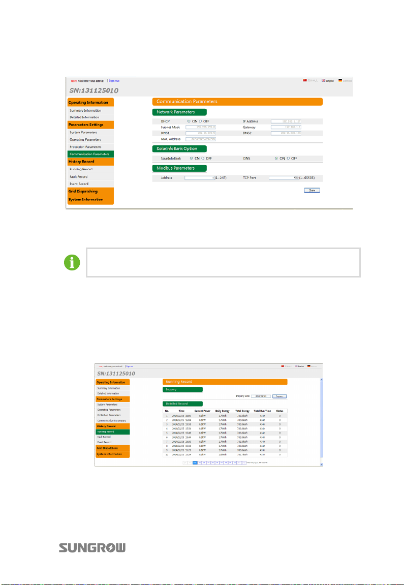
6.4.4 Communication Parameters
This interface is to set the related communication parameters. The newly set
parameters will not be effective immediately. System will adopt the new
communication parameter after exiting.
Both users and installers can set abovementioned communication
parameters.
6.5 History Record
History record includes the running record, fault record, and event record.
6.5.1 Running Record
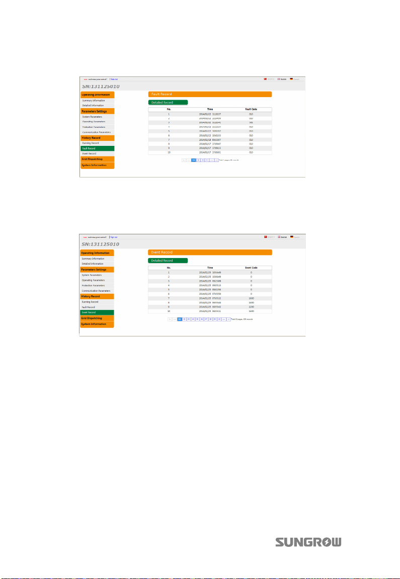
This interface is to search the running information of the inverter. The default display
is the running record of the preset day with 10 records in each page. If there is more
than 10 records, system will automatically list them in different pages.
55
Page 66
6 Visiting and Configuring the Webserver User Manual
6.5.2 Fault Record
This interface is to view the inverter detailed fault records.
At most 100 fault records can be stored with 10 records in each page.
6.5.3 Event Record
This interface is to view the inverter event records. At most 100 event records can be
stored with 10 records in each page.
6.6 Power Control Configuration
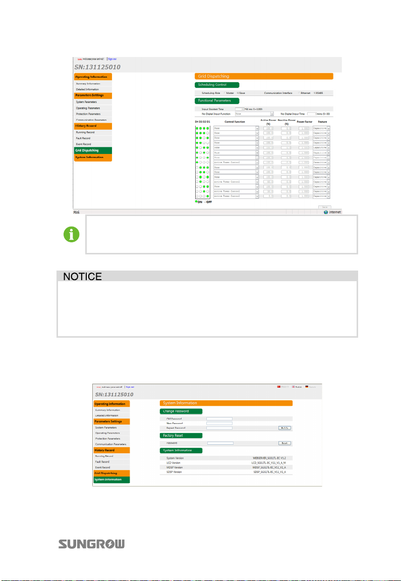
This interface is to set the grid dispatching parameters. The different statues of four
digital inputs are the configuration functions of corresponding actions.
Four inputs can be used to connect a power grid dispatch device (ripple control
receiver). A closed relay represents status 1 while open relay is 0.
The default state is 0000, which all four inputs are open. It cannot be applied to
power grid dispatch.
56
Page 67
User Manual 6 Visiting and Configuring the Webserver
In the event of Ethernet connection as shown in Fig. 5-9, inverter can be
the master or the slave during grid dispatch. If the inverter is the master,
it can dispatch other salve pieces through the NET port.
It is recommended to perform grid dispatching as per default setting of
each configuration status.
The change of related parameters must be done only by qualified
personnel. Any breach may void warranty claims from SUNGROW.
6.7 System Information
This interface is to change the login password, perform load default and check
system information.
57
Page 68
7 Commissioning
Commissioning is a critical part for a well-installed PV system, which can protect
against fires, injury and electrical shock.
7.1 Inspection before Commissioning
Before starting the inverter, you should check the items as follows.
1. The inverter is accessible for operation, maintenance and service.
2. Re-check and confirm that the inverter is firmly installed.
3. Space for ventilation is sufficient for one inverter or multiple inverters.
4. Nothing is left on the top of the inverter.
5. Inverter and accessories are correctly connected.
6. Cables are routed in safe place or protected against mechanical damage.
7. The selection of AC circuit breaker is optimal.
8. Terminals not used underneath the inverter are sealed.
9. Warning signs and labels are suitably affixed and durable.
7.2 Commissioning Procedure
If all the items mentioned above meet the requirements, proceed as follows to start
up the inverter for the first time.
1. Connect the external AC circuit breaker.
2. Rotate the DC switch to “ON” position.
Suppose there are sufficient sunlight and
enough DC power. PV arrays initialize and
supply DC power to inverter.
58
Page 69
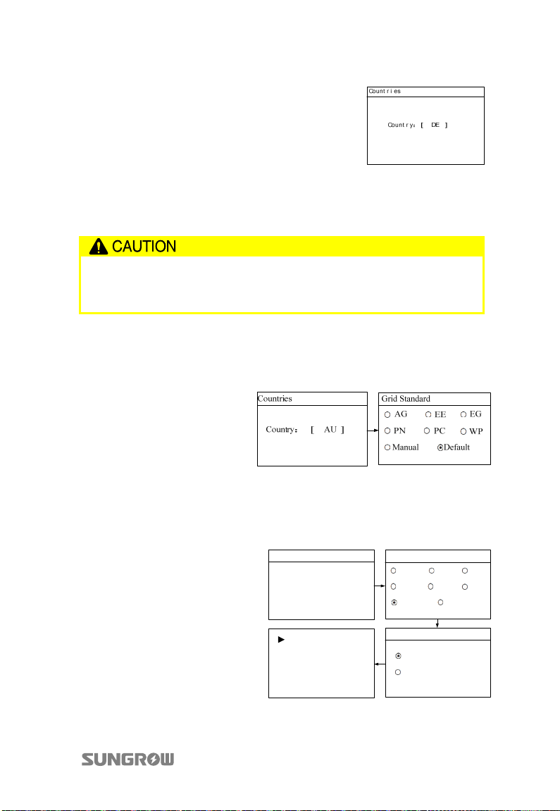
User Manual 7 Commissioning
3. Country selection screen will prompt.
Perform country settings with the right two
buttons. Detailed button functions can be
found in “10.1 Description of Button
Functio n”. Press
Confirm the settings by Pressing ENTER.
to choose country code.
Refer to “10.9.2 Selecting the Country Code” for country code explanation. If
the inverter is installed where the country code is not included, please choose
the item “Other” and manually set the protective parameters.
If the country code is not set correctly during commissioning, reset the
protective parameters as dictated in “10.9.2 Selecting the Country Code”.
There may be faults if otherwise.
4. (Optional) When the country code “AU” is selected, Press ENTER to
enter the “Grid Standard” interface. Press
/ to choose the correct grid
standard. Press ENTER to confirm the choice.
5. (Optional) When the country code “AU” and the grid standard “Manual”
are selected, Press ENTER to enter the “Pro-Stage” interface. Press
choose the correct stage. Press to move cursor and Press
/ to
to scroll up
time value. Confirm the settings by Pressing ENTER. The following figure
shows the settings of single-stage protection parameters.
Countries
Country:
Vgrid-max 260.0V
Vgrid-min 210.0V
Fgrid-max 52.00Hz
Fgrid-min 47.00Hz
[ AU ]
Grid Standard
AG EE EG
PN PC
Manual Default
Pro-Stage
Single-stage
Multi-stage
WP
59
Page 70
7 Commissioning User Manual
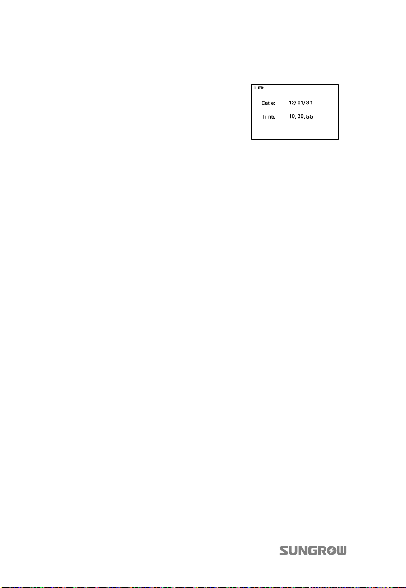
6. Configure time according to the local time.
Time setting is very important, which directly
affects data logging. Press to move cursor
and Press
to scroll up time value. Confirm
the settings by Pressing ENTER. The date
format is YY/MM/DD. YY, MM, and DD stand
for year, month, and day respectively. The
time format is hh/mm/ss. hh, mm, and ss
stand for hour, minute, and second
respectively.
If inverter’s commissioning fails, the “FAULT” indicator will be lit and “fault” will occur
on the display. Press to view “current fault” information. Remove the existing
malfunction and then repeat starting up inverter as the above procedures.
60
Page 71
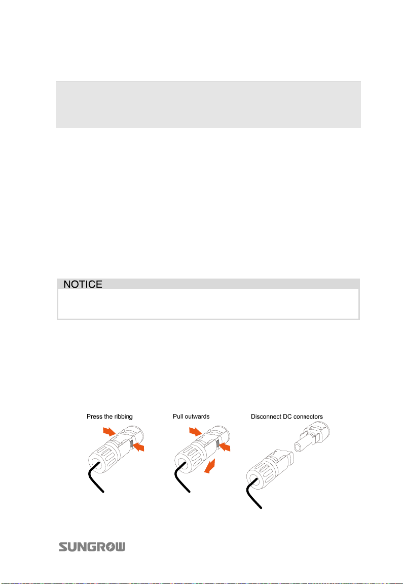
8 Disconnecting, Dismantling and
Disposing of the Inverter
8.1 Disconnecting the Inverter
For maintenance or other service work, the inverter must be switched off. In normal
operation, switching off is not necessary.
In order to disconnect the inverter from the AC and DC power sources, proceed as
follows. Lethal voltages or damages to the inverter will follow if otherwise.
1. Stop the inverter through operating the LCD menu. For details, see “10.6
Starting and Stopping the Inverter”.
2. Disconnect the external AC circuit breaker and prevent it from reconnecting.
3. Rotate the DC switch to the “OFF” position.
Please strictly follow the above procedures. Otherwise the inverter will not
function properly.
4. Wait for about ten minutes until the capacitors inside the inverter have
discharged.
5. Measure to confirm the AC output at the AC circuit breaker is voltage free.
6. Refer to “5.4.2 Assembling AC Cables to Connector” to release AC
connector out of the inverter in reverse steps.
7. Release the locking part of DC connectors by pressing on the ribbing of the
locking hooks with nipper pliers and pull it outwards.
61
Page 72
8 Disconnecting, Dismantling and Disposing of the Inverter user manual
For further disconnection and conductor reconnection instruction,
please visit the webpage of device manufacturer.
8.2 Dismantling the Inverter
Refer to Chapter 4 and Chapter 6 for the inverter dismantling in reverse steps. If
necessary, remove the wall bracket from the wall.
There is a risk of burn injuries and electric shock!
Wait at least 10 minutes after disconnecting the inverter from the utility
grid and the PV input before touching any inner live parts.
If the inverter will be reinstalled in the future, please refer to Chapter 4 and
Chapter 4.1 for a proper conservation.
8.3 Disposing of the Inverter
Users should take the responsibility for the disposal of the inverter.
Some parts and devices of the inverter, such as, LCD displayer, batteries,
capacitors, may cause environment pollution.
Users must comply with the related local regulations to avoid the potential
pollution.
62
Page 73
9 Troubleshooting and
Maintenance
9.1 Troubleshooting
9.1.1 Troubleshooting of LED Indicators
See “Tab. 2-2 Description of LED Indicators” for the definition of indicator states.
Fault Type Troubleshooting
LED indicators and LCD
screen cannot be lit
“RUN” indicator goes out 1. Disconnect AC circuit breaker.
“Fault” indicator is lit 1. A fault is not removed.
1. Disconnect the AC circuit breaker.
2. Rotate the DC Switch to the “OFF” position.
3. Check the polarity of DC input.
2. Rotate the DC Switch to the “OFF” position.
3. Check the correctness of electrical connection of
inverter. See “Fig. 5-1 Electrical Connection Diagram”.
4. Check whether DC input voltage exceeds the inverter
start voltage.
5. If all above conditions are OK, please contact
SUNGROW.
2. Perform troubleshooting in according to the fault
type in LCD screen. See “9.1.2 Troubleshooting of
Faults on LCD Screen”.
3. If it cannot be solved, please contact SUNGROW.
9.1.2 Troubleshooting of Faults on LCD Screen
When faults occur, “Fault” state will be shown on the main screen. Press to view
multiple “current fault” information pages.
Code of
fault
002
Specification Troubleshooting
1. Check the voltage of the grid.
The grid voltage has
exceeded inverter
allowable upper limit.
63
2. If the grid voltage exceeds the
permissible range of inverter protective
parameters, ask utility grid company for
solution.
3. If the grid voltage is within the
permissible range, contact SUNGROW
Page 74
9 Troubleshooting and Maintenance User Manual
Code of
fault
003
004
005
007
008
009
010 Islanding
011
012
014
015
Specification Troubleshooting
Inverter has checked that
the instantaneous sample
value of the grid voltage
exceeds the allowable
limit for some time.
The grid voltage has fallen
below inverter’s allowable
lower limit.
The grid voltage is too
low.
Inverter has checked AC
overcurrent temporarily.
The grid frequency has
exceeded inverter
allowable upper limit.
The grid frequency has
fallen below inverter
allowable lower limit.
The DC component of AC
current has exceeded
inverter limit.
Inverter has detected that
there is a leakage current.
The average grid voltage
is not within the
permissible range for over
10 minutes.
The grid impedance is too
high.
Service Dept..
1. This is a short-term fault due to grid
condition. Wait a moment for inverter
recovery.
2. If the fault still exists, please contact
SUNGROW Service Dept..
1. Check the voltage of the grid.
2. If the grid voltage exceeds the
permissible range of inverter protective
parameters, ask utility grid company for
solution.
3. If the grid voltage is within the
permissible range, contact SUNGROW
Service Dept..
1. The inverter will resume if the output
current falls below the protective value.
2. If the fault still exists, please contact
SUNGROW Service Dept..
1. Check the frequency of the grid.
2. If the grid frequency exceeds the
permissible range of inverter protective
parameters, ask utility grid company for
solution.
3. If the grid frequency is within the
permissible range, contact SUNGROW
Service Dept..
1. Check whether AC circuit breaker is
triggered.
2. Check whether AC cables are all firmly
connected.
3. Check whether grid is not on service.
4. If all conditions are OK and this fault still
occurs in the LCD screen, contact
SUNGROW Service Dept..
1. Wait a moment for inverter recovery.
2. Contact SUNGROW if the fault reoccurs.
1. Check the PV strings for ground fault.
2. Contact SUNGROW if the fault reoccurs.
1. Check whether the grid is operating
normally.
2. Wait a moment for inverter recovery.
3. Contact SUNGROW if the fault reoccurs.
1. Check whether the grid is operating
normally.
64
Page 75
User Manual 9 Troubleshooting and Maintenance
Code of
fault
017
019
021
022
024
037
038
041
042 Current imbalance.
043
044
045
046
048
Specification Troubleshooting
The inverter has detected
that there is unbalance
among the three phase
voltages. (Only valid in
Austria.)
The bus voltage is
temporarily high.
Inverter has checked that
there is overcurrent of PV1
input.
Inverter has checked that
there is overcurrent of PV2
input.
Inverter has checked the
deviation of neutral point
voltage.
Enclosure over-temp
The ambient temperature
of the enclosure exceeds
the threshold.
Relay fails.
Relay is in poor contact.
Leakage current sampling
channel fault.
The ambient temperature
is too low.
A fault is detected during
inverter self-detection.
DC-AC conversion fails.
Faults detected in PV1
boosted circuit.
Faults detected in PV2
boosted circuit.
Phase-R current sampling
channel fault.
2. Check AC cables for appropriate size.
3. Wait a moment for inverter recovery.
4. Contact SUNGROW if the fault reoccurs.
1. Wait a moment for inverter recovery.
2. Contact SUNGROW if the fault reoccurs.
1. Wait a moment for inverter recovery.
2. Contact SUNGROW if the fault reoccurs.
Check the layout and the wiring of PV1
input.
Check the layout and the wiring of PV2
input.
1. The inverter will recover if the deviation
value falls below the protective limit.
2. Contact SUNGROW if the fault reoccurs.
1. Check whether AC output power
exceeds nominal power too much.
2. Check whether fans work normally and
whether there are some abnormal fans.
Please replace broken fan, in necessary.
3. Clean air grills of outlet.
4. If the fault still exists, please contact with
SUNGROW.
1. Wait a moment for inverter recovery.
2. Contact SUNGROW if the fault reoccurs.
1. Wait a moment for inverter recovery.
2. Contact SUNGROW if the fault reoccurs.
1. Wait a moment for inverter recovery.
2. Contact SUNGROW if the fault reoccurs.
The inverter will recover if the ambient
temperature rises above the protective
limit.
1. Wait a moment for inverter recovery.
2. Contact SUNGROW if the fault reoccurs.
1. Wait a moment for inverter recovery.
2. Contact SUNGROW if the fault reoccurs.
1. Wait a moment for inverter recovery.
2. Contact SUNGROW if the fault reoccurs.
65
Page 76
9 Troubleshooting and Maintenance User Manual
T
Code of
fault
049
050
100
101
102
103
104
200
202
203
300-301
302
Specification Troubleshooting
Phase-S current sampling
channel fault.
Phase-T current sampling
channel fault.
Inverter overcurrent
hardware protection.
AC current has exceeded
the hardware limit.
Grid over-frequency.
Grid frequency is outside
the permissible range.
Grid under-frequency.
Grid frequency is outside
the permissible range.
Grid voltage
synchronization fault.
The grid voltage sampling
differences between the
master and slave DSP.
Grid frequency
synchronization fault;
The grid voltage sampling
differences between the
master and slave DSP.
1. Wait a moment for inverter recovery.
2. Contact SUNGROW if the fault reoccurs.
1. Check the voltage of the grid.
2. If the grid voltage exceeds the
permissible range of inverter protective
parameters, ask utility grid company for
solution.
3. If the grid voltage is within the
permissible range, contact SUNGROW
Service Dept..
1. Wait a moment for inverter recovery.
2. Contact SUNGROW if the fault reoccurs.
he bus voltage exceeds
the set value of the
hardware.
PV1 or PV2 current
exceeds the set value of
the hardware.
The PV input voltage
exceeds the bus voltage.
The temperature of some
components inside the
cabinet is too high
PV insulation resistance
fault.
1. Wait a moment for inverter recovery.
2. Contact SUNGROW if the fault reoccurs.
1. Check the functionality of the PV
connection terminal.
2. Contact SUNGROW if the fault reoccurs.
1. Check the functionality of the fans.
2. Clean the air inlet and outlet.
3. Clean air grills of outlet.
4. If the fault still exists, please contact
SUNGROW.
1. Check whether the PV connection cables
are intact.
2. Check whether the ambient humidity of
PV components is too high.
66
Page 77
User Manual 9 Troubleshooting and Maintenance
Code of
fault
307
308
309-318
320
401-409 Permanent faults.
501-502
503-508
510
511
512 Fan low-speed warning.
513 Fan blocking warning.
514
515
Specification Troubleshooting
Open circuit voltage of
the PV array is too high,
leading the input power
exceeds the permissible
range.
Accessory processor fault.
Redundant fault detected.
Voltage and current
sampling fault before grid
connection.
Leakage current CT
self-check fault.
Inverter internal
communication failure.
Temperature sensor
warnings.
The PV panel
configuration exceeds the
optimum operating range
of the inverter.
Open circuit warning of
the temperature sensor.
Communication failure
between the meter and
the LCD.
Boost short circuit
warning.
3. Wait until the inverter reverts to normal;
4. Contact SUNGROW if the fault reoccurs.
1. Check whether the configuration of PV
array exceeds the permissible range of the
inverter.
2. Wait a moment for inverter recovery.
3. Contact SUNGROW if the fault reoccurs.
1. Wait a moment for inverter recovery.
2. Contact SUNGROW if the fault reoccurs.
1. Wait a moment for inverter recovery.
2. Contact SUNGROW if the fault reoccurs.
1. Wait a moment for inverter recovery.
2. Contact SUNGROW if the fault reoccurs.
1. If there are no other problems and the
inverter is required to keep operating,
restart the inverter immediately.
2. Contact SUNGROW if the fault reoccurs.
Contact SUNGROW if the fault reoccurs.
Contact SUNGROW if the fault reoccurs.
1. Check whether the configuration of PV
array exceeds the permissible range of the
inverter.
2. Contact SUNGROW if the fault reoccurs.
1. Wait a moment for inverter recovery.
2. Contact SUNGROW if the fault reoccurs.
1. Check the functionality of the fans;
2. Clean the air inlet and outlet;
3. Clean air grills of outlet.
4. If the fault still exists, please contact
SUNGROW.
1. Inverter can be connected to the grid
normally.
2. Contact SUNGROW if the fault reoccurs.
Please contact SUNGROW Service Dept..
67
Page 78
9 Troubleshooting and Maintenance User Manual
Should you have any problems in operating the inverter, please contact
us:
Service hotline: +86 551 6532 7834/6532 7845
Email: [email protected]
We need the following information to provide you the best assistance:
Type of the inverter
Serial number of the inverter
Fault code/name
Brief description of the problem
9.2 Maintenance
9.2.1 Routine Maintenance
Item Method Period
Save data Save the running data, parameters and log to
General
state of
system
System
clean
Electrical
connection
Fan Check whether there is crack of the fan blade
a disk or a file.
Visual check for any damage or deformation
of the inverter.
Check any abnormal noise during the
running of the inverter.
Check each parameter of inverter operation.
Check if the temperature of the housing is
normal. Monitor the system using the thermal
imager.
Check the temperature and dust of the
inverter. Clean the inverter enclosure,
especially the heat sink. Check the humidity
and dust of the environment. Meanwhile
check whether the filter function of the air
inlet is ok. Clean the air inlet and outlet, when
necessary.
Check whether cable connections are loose.
Tighten the loose connections.
Check whether there is damage the cables,
especially the surface in contact with metal.
Check whether the wrap belt of the
connection terminals is strip-off.
Check whether there is any abnormal noise
when the fan is turning.
Once 31 days
Every 6 months
Six months to a year
(it depends on the
dust contents in air.)
Six months after
commissioning and
then once or twice a
year.
Once a year
68
Page 79
User Manual 9 Troubleshooting and Maintenance
Item Method Period
Clean or replace the fan.
Once or twice a year
Once or twice a year
Safety
function
Software
Check the LCD stop and emergency stop
circuit of the system.
Simulate shutdown and check stop signal
communication.
Check the warning labels, and replace them if
necessary.
Software optimization.
Check the setting of every parameter.
9.2.2 Maintenance Instruction
Disconnect the inverter from the grid first and then PV arrays before any
maintenance work.
Lethal voltage still exists in the inverter. Please wait at least ten minutes and
then perform maintenance work.
Replacing Fan
If there is overheat and abnormal noise, please wait a moment for the fan recovery.
If the abnormal noise still exists after a moment, please contact SUNGROW Service
Dept. to replace the fan.
Disconnect the inverter from the grid first and then PV arrays before any
maintenance work.
Fans’ maintenance work may only be performed by qualified electricians.
Air Inlet and Outlet Cleaning
Check whether there is anything blocking the air inlet and outlet to maintain good
ventilation.
Clean the air inlet and outlet with soft brush or vacuum cleaner if necessary.
Battery Maintenance
There is a button battery on the inner LCD PCB board. Contact SUNGROW Service
Dept. to replace the battery when it is end of service life.
69
Page 80
10 Operating the LCD Menu
10.1 Description of Button Function
Inverter offers two buttons for the user to look up the running information and
configure parameters. The two buttons have multiple functions. Please refer to Tab.
10-1 before any operation onto inverter.
Tab. 10-1 Button Function
Button Operation Description
Press less than one
second
Press more than
one second
Press less than one
second
Press more than
one second
Move upwards or downwards, or increase setting
value. Hereinafter, it is referred to as “Press ”.
Return to the previous menu or cancel the
command. Hereinafter, it is referred to as “Press
ESC”.
Move left or right, or turn pages. Hereinafter, it is
referred to as “Press ”.
Enter into the submenu or confirm the command.
Hereinafter, it is referred to as “Press ENTER”.
The background illumination of the LCD screen will go out to save power
if there is no button operation for one minute. Reactivate it by pressing
any button.
70
Page 81
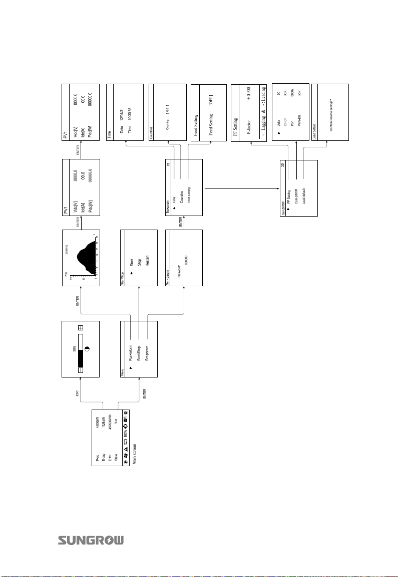
User Manual 10 Operating the LCD Menu
10.2 Inverter Menu Structure
Fig. 10-1 Menu Tree-English
71
Page 82
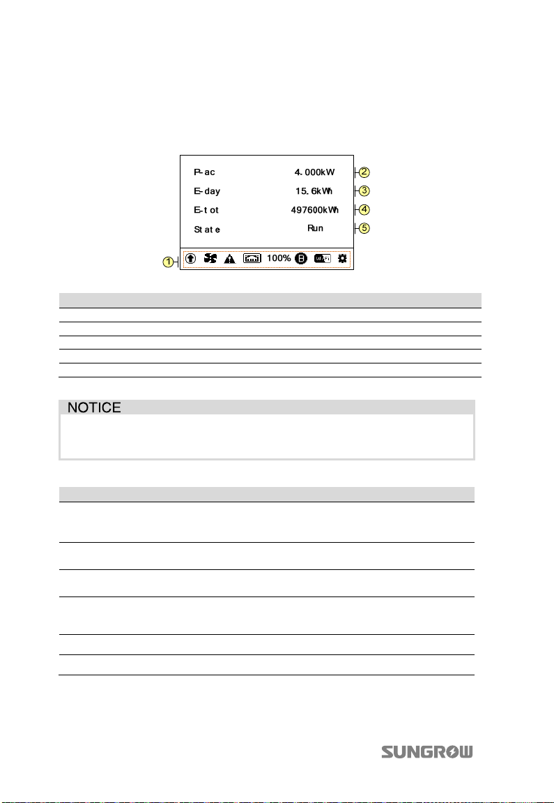
10 Operating the LCD Menu User Manual
T
10.3 Main Screen
If the inverter succeeds in commissioning, LCD display will enter into the main
screen, as shown in Fig. 10-2.
Fig. 10-2 Main Screen Description
No. Description
1 Icons (refer to the Tab. 10-3) and the active power limits (P-W limits).
2 Current output power.
3 Energy generation during this day until now.
4 Total energy generation since initial commissioning.
5 Inverter state.
The energy yields displayed by the LCD panel are indicative only.
For the actual yields, please refer to the electric energy meter.
Tab. 10-2 Inverter State Description
Inverter State Description
Run
Standby
Key-stop
Ini-standby
Startup The inverter is initializing and synchronizing with the grid.
Com-err Inverter internal communication failure.
After being energized, the inverter tracks the PV arrays’ maximum
power point (MPP) and feeds AC power to grid. This mode is the
normal mode.
In this mode the inverter will wait for sufficient sunlight and the
DC voltage recovers. The PV voltage is more than 230V.
The inverter will stop operation by manual “stop” through LCD
menu.
he state when inverter is power-on for the first time. The PV
voltage is less than 230V.
72
Page 83
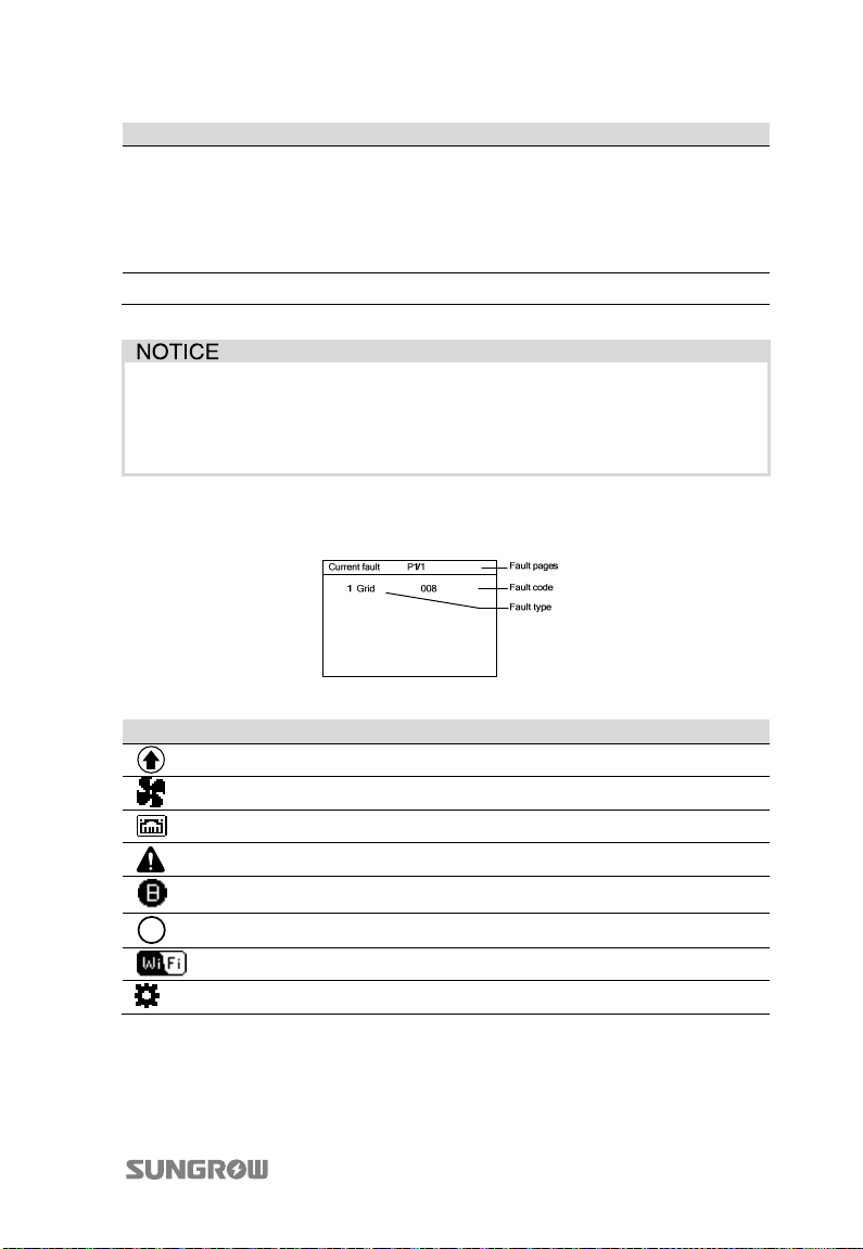
User Manual 10 Operating the LCD Menu
Inverter State Description
If a fault occurs, the inverter will automatically stop operation,
trigger the AC relay and show “Fault” on the LCD with the “FAULT”
Fault
Upd-fail The master DSP program online upgrade failure.
indicator lit.
Once the fault is removed in recovery time (set by user, see “9.1.2
Troubleshooting of Faults on LCD Screen”), the inverter will
automatically resume running.
If the device is in standby mode for more than 10 minutes, please check if
the insolation is sufficient and the PV connection is correct.
If no anomaly is found, disconnect DC switch and grid switch to restart.
If it still does not work, contact SUNGROW.
If inverter is in “Fault” state, Press to view multiple “Current fault” information
pages. To know the specific fault information, please refer to “9.1.2
Troubleshooting of Faults on LCD Screen”.
Tab. 10-3 Description of icons
Icon Description
B
DSP or LCD is in IAP update process.
Fan inside is working.
The Ethernet communication cable is active.
Inverter is in warning state.
The inverter is successfully connected to Bank server via Ethernet.
The inverter is successfully connected to Bank server via Wi-Fi.
Wi-Fi has connected to the router. Blink when connection failure.
Wi-Fi is waiting to be connected to the router.
73
Page 84
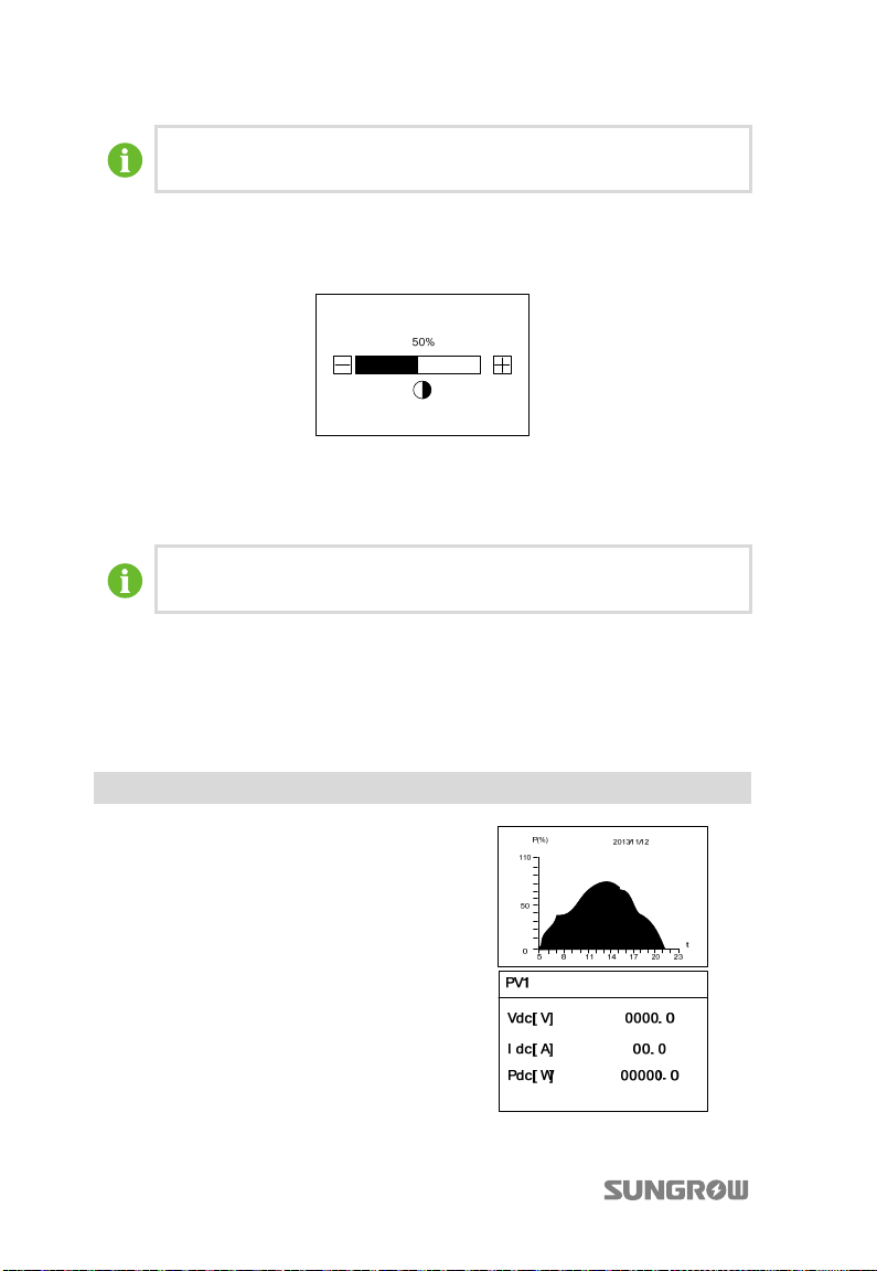
10 Operating the LCD Menu User Manual
The last three icons don’t exist when access the APP of SolarInfo Bank in
local mode.
10.4 Adjusting Contrast
1. Press
ESC to enter into the contrast adjustment screen.
2. Press
to increase the setting value and press to decrease the value.
ENTER to confirm the contrast setting.
3. Press
The contrast value ranges from 0 to 100. The recommended value is 50 or
60.
10.5 Viewing Detailed Running Information
On the main screen, there is some basic information about the inverter. For more
detailed running information, please operate as follows.
Main Screen(Press ENTER)→Menu→Run-inform(Press ENTER)
LCD screen will show detailed running information. Scroll pages by pressing /.
Power curve during this day until now.
Vdc: DC voltage of PV1 input.
Idc: DC current of PV1 input.
Pdc: DC power of PV1 input.
74
Page 85
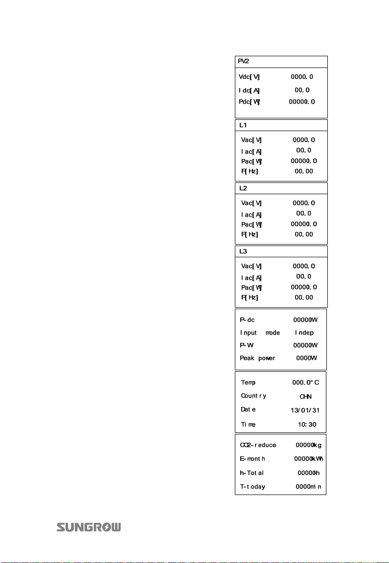
User Manual 10 Operating the LCD Menu
Vdc: DC voltage of PV2 input.
Idc: DC current of PV2 input.
Pdc: DC power of PV2 input.
Vac: Voltage of L1.
Iac: Current of L1.
Pac: AC output of L1.
F: Frequency of L1.
Vac: Voltage of L2.
Iac: Current of L2.
Pac: AC output of L2.
F: Frequency of L2.
Vac: Voltage of L3.
Iac: Current of L3.
Pac: AC output of L3.
F: Frequency of L3.
P-dc: Inverter input power.
Input mode: Inverter input connection mode.
P-W: Inverter output active power.
Peak-Power: Daily peak power value.
Temp: Internal temperature of the inverter.
Country: Country code selected.
Date: Current date.
Time: Current time.
CO2-reduce: Total CO2 emission reduction due to
the inverter.
E-month: The energy generated in this month.
h-Total: Total running hours of the inverter.
T-today: Daily running time of the inverter.
75
Page 86
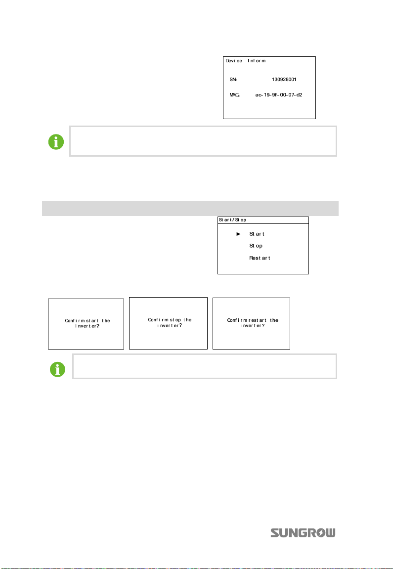
10 Operating the LCD Menu User Manual
SN: Serial number.
MAC: Physical address.
The power value indicated by each column of the histogram represents
the average value of the power during the related unit interval.
10.6 Starting and Stopping the Inverter
Main Screen(Press ENTER)→Menu(Press ×1)→Start/Stop(Press ENTER)
Press to choose “Start”/”Stop” and press
ENTER to confirm the choice.
Confirm your choice by pressing ENTER.
The Restart item will appear only if an unrecoverable fault occurs.
10.7 Inputting Password
The parameter settings are protected by the password. If you want to set the
inverter’s parameters, you have to input the correct password.
1. Press ENTER to enter into “Menu” screen.
2. Press
76
to move the cursor to “Set-param” menu item and confirm by
pressing ENTER.
Page 87
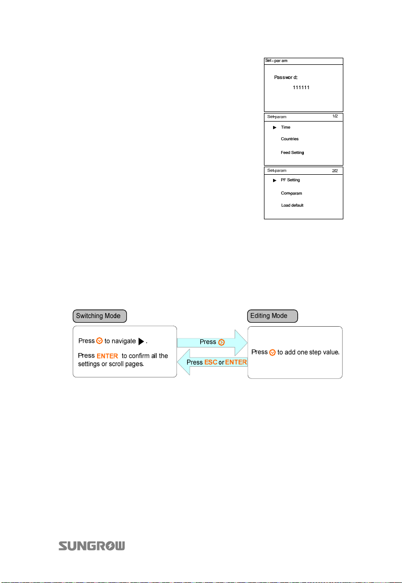
User Manual 10 Operating the LCD Menu
3. A password confirmation screen will occur.
Press to move cursor right and Press
input the password 111111.
4. Press ENTER to confirm the password and
enter the “Set-param” submenu.
to
10.8 Button Operation for Parameters Setting
The button functions for parameter setting in submenus may differ from that in
other menus.
Proceed as follows to perform the parameter settings.
10.9 Setting Parameters
10.9.1 Setting the Time
If there is deviation between the time on inverter main screen and your local time,
you should perform the operation time setting. Otherwise the inverter data logging
will fail. Clock is 24-hour format.
The date format is YY/MM/DD. YY, MM, and DD stand for year, month, and day
respectively. The time format is hh/mm/ss. hh, mm, and ss stand for hour, minute,
and second respectively.
77
Page 88
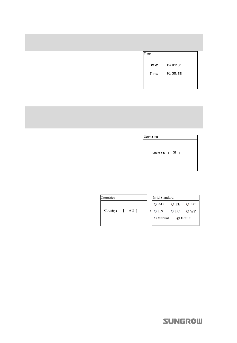
10 Operating the LCD Menu User Manual
Main Screen (Press ENTER)→Menu screen (Press ×2)→Set-param (Press
ENTER)→Enter password (Press ENTER)→Time (Press ENTER)
On the “Time” screen, Press to move the cursor
right and Press to set the correct date and time.
Confirm settings by pressing ENTER.
10.9.2 Selecting the Country Code
Main Screen (Press ENTER)→ Menu screen (Press × 2) →Set-param (Press
ENTER)→Enter password (Press ENTER)→Set-param (Press ENTER, Press ×1)→
Countries (Press ENTER)
To make protective parameters setting convenient,
inverter provides country code selection. The country
code has been configured before delivery according
to different countries utility grid requirements.
Choose the correct country code by Press and
Press ENTER to confirm.
1. (Optional) When the country code “AU” is selected, Press ENTER to
enter the “Grid Standard” interface. Press
standard. Press ENTER to confirm the choice.
/ to choose the correct grid
78
Page 89
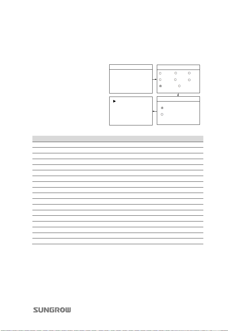
User Manual 10 Operating the LCD Menu
2. (Optional) When the country code “AU” and the grid standard “Manual”
are selected, Press ENTER to enter the “Pro-Stage” interface. Press
/ to
choose the correct stage. Press to move cursor and Press to scroll up
time value. Confirm the settings by Pressing ENTER. The following figure
shows the settings of single-stage protection parameters.
Countries
Country:
[ AU ]
Grid Standard
AG EE EG
PN PC
Manual Default
WP
Vgrid-max 260.0V
Vgrid-min 210.0V
Fgrid-max 52.00Hz
Fgrid-min 47.00Hz
Pro-Stage
Single-stage
Multi-stage
The description of country code is illustrated below:
Country Code Full Name Language
GB Great Britain English
DE Germany German
FR France French
IT Italy Italian
ES Spain English
AT Austria German
AU Australia English
CZ Czech English
BE Belgium French
DK Denmark English
GR_L Greece Land English
GR_IS Greece Island English
NL Netherlands English
PT Portugal English
CHN China Chinese
SE Sweden English
VB(DE) Vorarlberg German
Other Country not included above English
79
Page 90
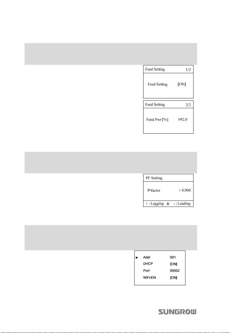
10 Operating the LCD Menu User Manual
10.9.3 Feed Setting
Main Screen (Press ENTER)→ Menu screen (Press × 2) →Set-param (Press
ENTER)→Enter password (Press ENTER)→Set-param (Press ENTER, Press ×2)→
Feed Setting (Press ENTER)
Press / to enable or disable the feed setting
and Press ENTER to confirm.
Press to move cursor and Press to set the
value. Confirm the settings by Pressing ENTER.
10.9.4 PF Setting
Main Screen (Press ENTER)→ Menu screen (Press × 2) →Set-param (Press
ENTER)→Enter password (Press ENTER)→Set-param (Press ENTER, Press ×3)→
PF Setting (Press ENTER)
Press to move cursor and Press to set the
power factor. Confirm the settings by Pressing
ENTER.
10.9.5 Setting Communication Parameters
Main Screen (Press ENTER)→Menu screen (Press ×2)→Set-param (Press
ENTER)→Enter password (Press ENTER)→Set-param (Press ENTER, Press
×4)→Com-param (Press ENTER)
Press to move cursor right and Press to set
the appropriate value. Confirm settings by Pressing
ENTER.
The range of communication address is 1...247.
WiFi-EN ON: Wi-Fi function enabled.
WiFi-EN OFF: Wi-Fi function disabled.
80
Page 91
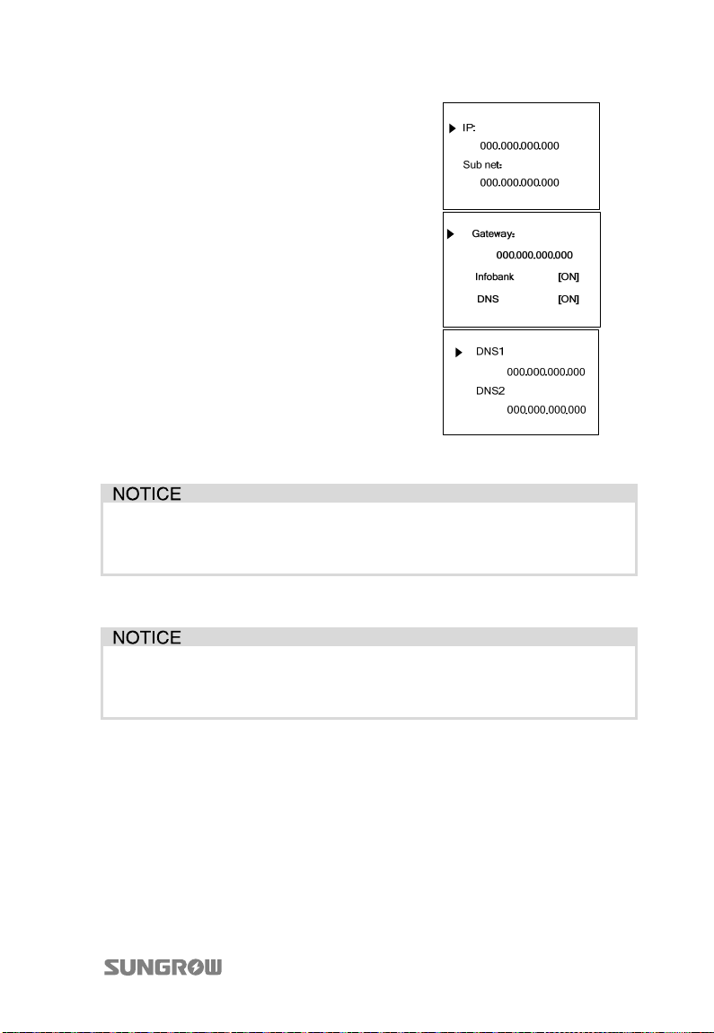
User Manual 10 Operating the LCD Menu
Scroll pages by pressing ENTER.
Apply an IP address, subnet mask, default gateway and port number for the inverter
from your network administrator.
If there is more than one inverter and all the inverters are set to DHCP [OFF],
a unique IP address should be assigned to each inverter. The configuration
procedure should be performed only by qualified personnel.
10.9.6 Load Default
All history information will be unrecoverable cleared and all parameters will
return to the default value except the protective parameters and time once
the “load default” operation is performed.
81
Page 92
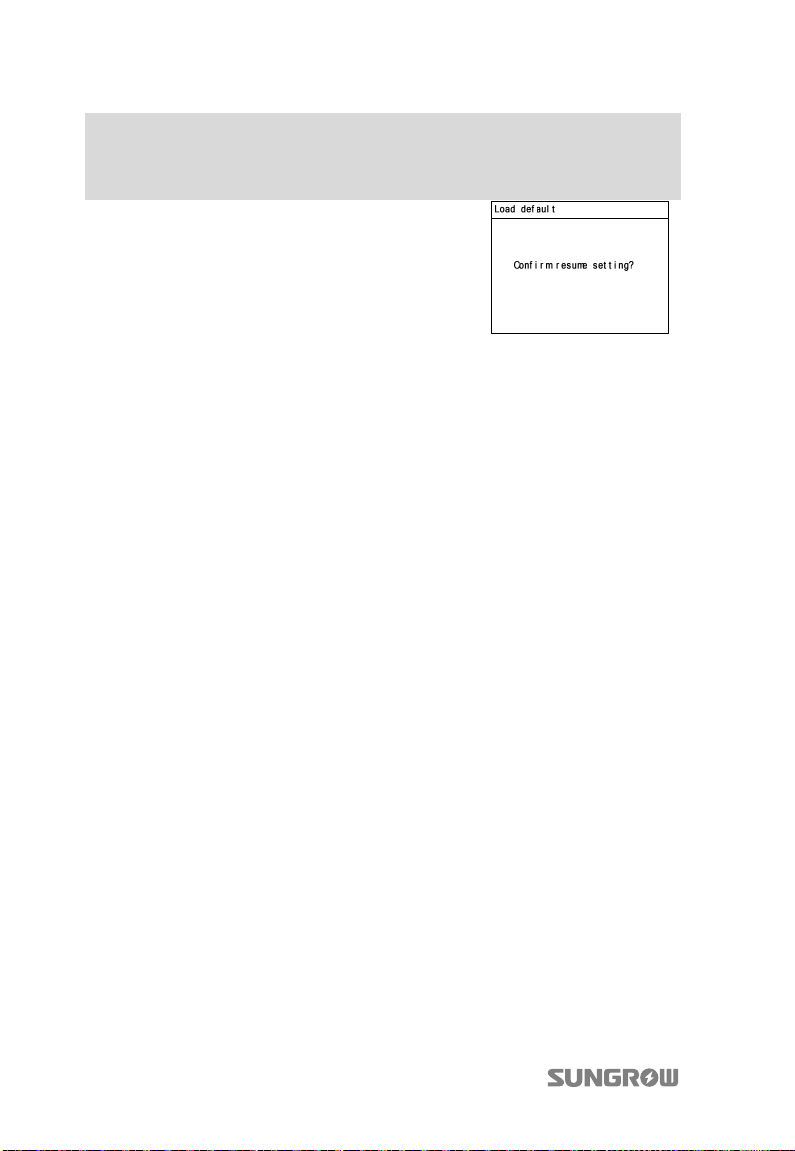
10 Operating the LCD Menu User Manual
Main Screen (Press ENTER)→Menu screen (Press ×2)→Set-param (Press
ENTER)→Enter password (Press ENTER)→Set-param (Press ENTER, Press
×5)→Load Default (Press ENTER)
Press ENTER to confirm “load default”.
82
Page 93
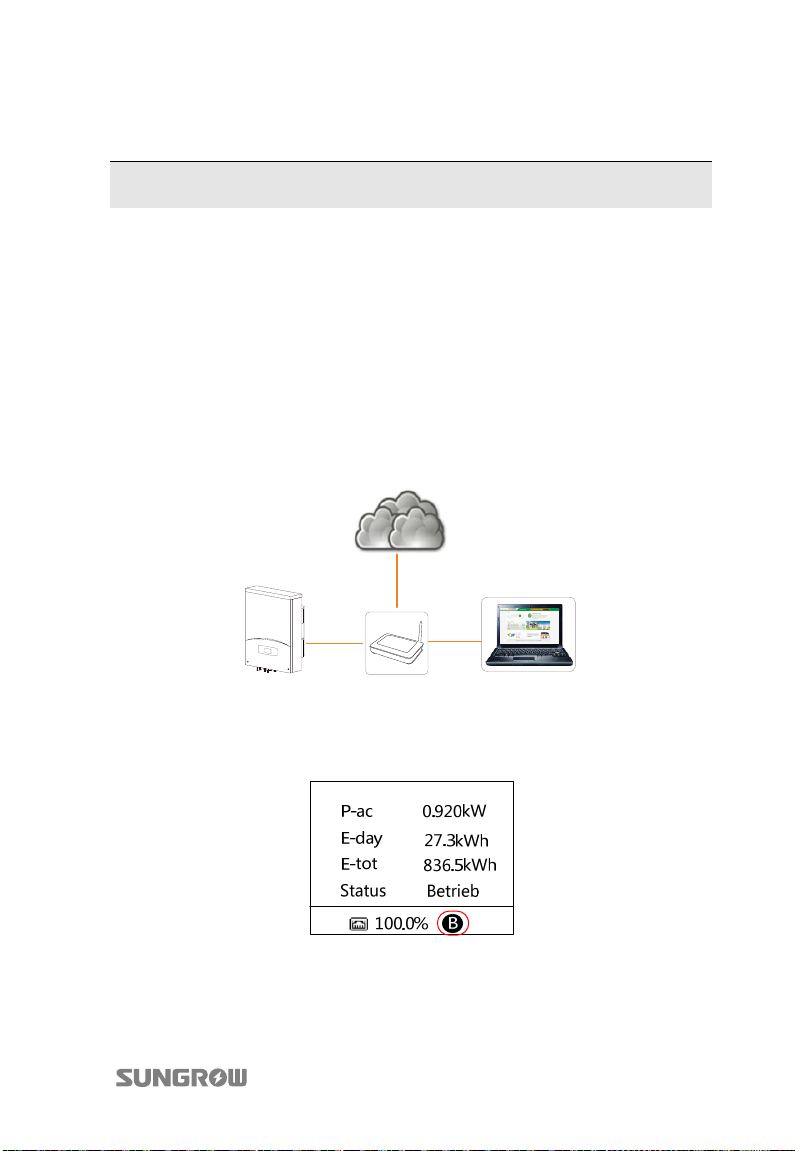
11 Viewing PV Plant Information
After registering on the webpage www.solarinfobank.com, users can view PV plant
information through the PC or smartphone. Users can also view PV plant
information through the APP of SolarInfo Home installed into the smartphone.
11.1 SolarInfo Bank Connection
11.1.1 For Common User
1. Connect the communication cable between router and inverter, and connect
the communication cable between router and PC.
SolarInfo Bank
Inverter
2. Wait for about 10 minutes and the icon as shown in the figure below will
appear on the main LCD display screen. The SolarInfo Bank connects to the
inverter successfully.
3. Open the explorer, input the webpage www.solarinfobank.com in the
address bar. Register and then visit SolarInfo Bank. For details, see “11. 2
Registration and Adding PV Plant”.
83
Router/Switch
PC
Page 94
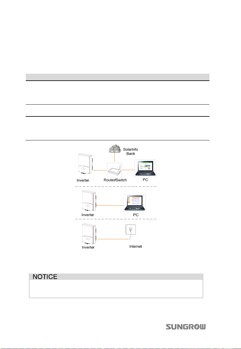
11 Viewing PV Plant Information User Manual
4. View the plant information via SolarInfo Home APP in remote ”[Login]” mode,
see “Visit in “Remote [Login]”mode”.
11.1.2 For Professional User
The following table shows the three scenarios of connection for professional user.
No. Description Remarks
Scenario 1 The inverter is connected to router,
and the router is connected to the PC.
The router cannot allocate IP address
automatically.
Scenario 2 The inverter is connected directly to
PC.
Scenario 3 The inverter is connected directly to
the net port.
The computer can visit
SolarInfo Bank only when the
router can access to Internet.
The computer cannot visit
SolarInfo Bank.
Contact service engineer of
SUNGROW when the inverter
and the PC are in different
subnets.
1. Connect the communication cable.
2. Set the DHCP to OFF and set the IP address, subnet mask, gateway, DNS1 and
DNS2, as shown in the following figure.
Acquire the IP, subnet mask, gateway, DNS1 and DNS2 from the network
professional. The information shown below is for reference only.
84
Page 95
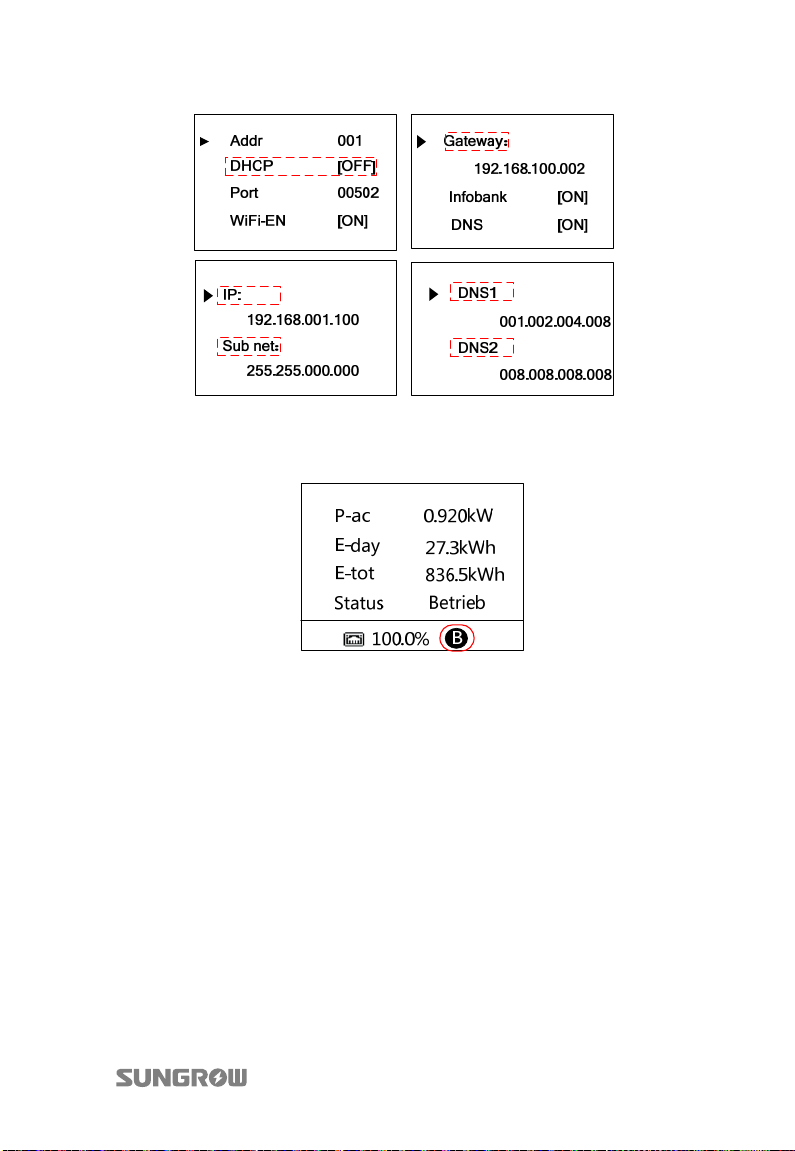
User Manual 11 Viewing PV Plant Information
3. Wait for about 10 minutes and the icon as shown in the figure below will
appear on the main LCD display interface. The SolarInfo Bank connects to the
inverter successfully.
4. (Optional) Do this step only for scenario 2. Proceed as follows to configure
the IP address and subnet mask of the computer.
− For Windows 7 or higher version, right click the [Network and Internet] icon
on the right corner of the desktop, click [Network and Sharing Center], open
[Local Area Connection], click [Properties], double click [Internet Protocol
Version 4 (TCP/IPv4)], click [Use the following IP address].
− For Windows XP, right click [My Network Places], open [Local Area Connection],
click [Properties], and double click [Internet Protocol (TCP/IP), and then click
[Use the following IP address].
85
Page 96
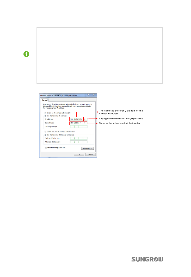
11 Viewing PV Plant Information User Manual
IP address format:
First 9 digitals of the IP address: the same as the first 9 digitals of the
inverter IP address. Example: if the inverter IP address is
192.168.001.100, you must input 192.168.001 for the first 9 digitals of
computer IP address.
Last 3 digitals of the IP address: any digital between 0 and 255 (expect
for the last 3 digitals of the inverter IP address), for example 101.
So the IP address is 192.168.001.101.
Subnet mask of the computer:
Must be the same as that of the inverter, i.e. 255.255.000.000.
5. Open the explorer, input the inverter IP address in the address bar to enter
the WebServer login interface. Input the user name and password which are
user and 1111 respectively by default, and then press Enter. WebServer is
connected successfully.
6. Open the explorer, input the webpage www.solarinfobank.com in the
address bar. Register and then visit SolarInfo Bank. For details, see “11. 2
Registration and Adding PV Plant”.
7. View the plant information via SolarInfo Home APP in remote ”[Login]” mode,
see “Visit in “Remote [Login]”mode”.
86
Page 97
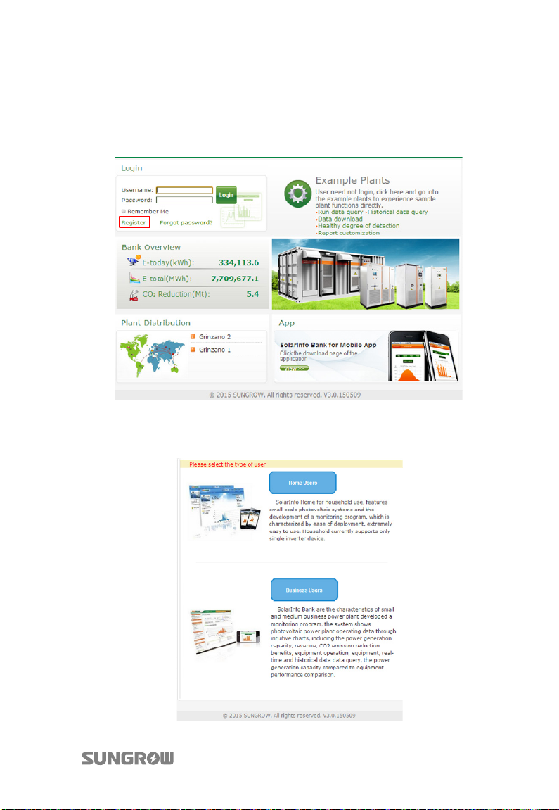
User Manual 11 Viewing PV Plant Information
11.2 Registration and Adding PV Plant
1. Open a browser and enter the webpage www.solarinfobank.com to view the
homepage of SolarInfo Bank. Register a new user by clicking “Register”.
2. The registration interface as shown below will appear. User can select Home
users or Business users according to real situation. Select Home users for
residential use. Select Business users for commercial use.
87
Page 98
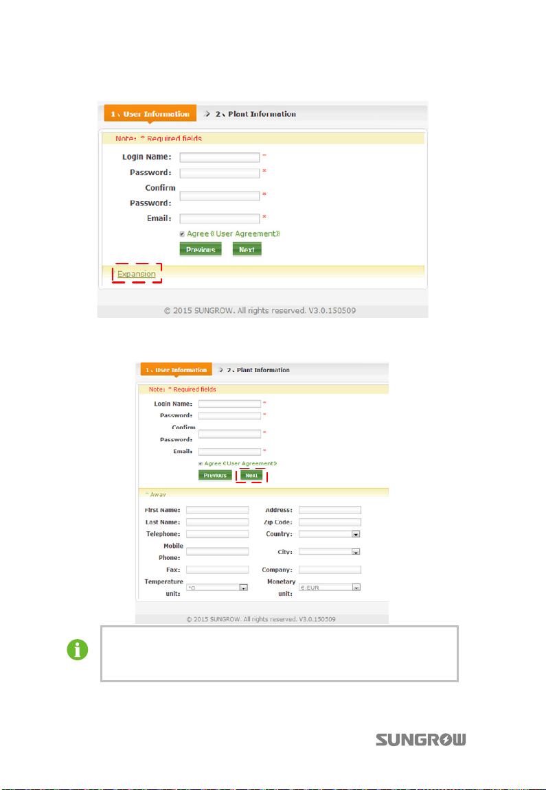
11 Viewing PV Plant Information User Manual
3. Fill in the user information in the following interface.
Click Expansion to fill in more information in the following interface. Then click
Next.
The Country, City, Monetary unit and Temperature unit can be
selected from the drop-down list. For other items, user must fill in
manually.
88
Page 99
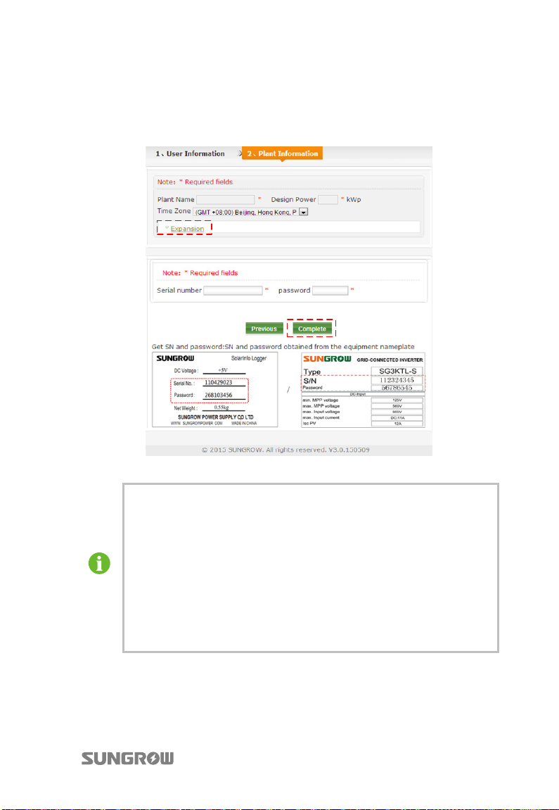
User Manual 11 Viewing PV Plant Information
T
4. Fill in the plant information in the following interface. Click Expansion to fill
in more information. Click Complete to finish the registration and click
Previous to return for modification. If the Home users is selected in step 2,
the registration process is finished by now.
*The nameplate in the figure is for reference only.
ime Zone must be selected according to the installation place of the
inverter. If user does not know the local time zone, please check in
Google map.
If new devices are added, please fill in the related information in the
following format:
− Serial number: the serial number shown on the device nameplate.
− Password: the same as the serial number and should be input
manually.
− Device name: the same as the device serial number by default and
can be changed by the user.
89
Page 100
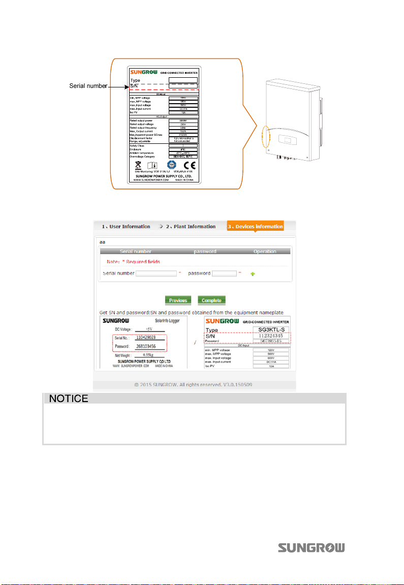
11 Viewing PV Plant Information User Manual
5. Proceed as follows to fill in the Devices Information if the Business users is
selected in step 2.
The format of Serial number, Password, and Device name are the same as
that in Step 4. Click Complete to finish the registration and click Previous to
return to the previous page to modify information.
6. Refresh the webpage www.solarinfobank.com, then you can see the data of
the corresponding PV plant. For detailed information about the items, see
“SolarInfo Bank User Manual”.
90
 Loading...