

Page 1
3
0
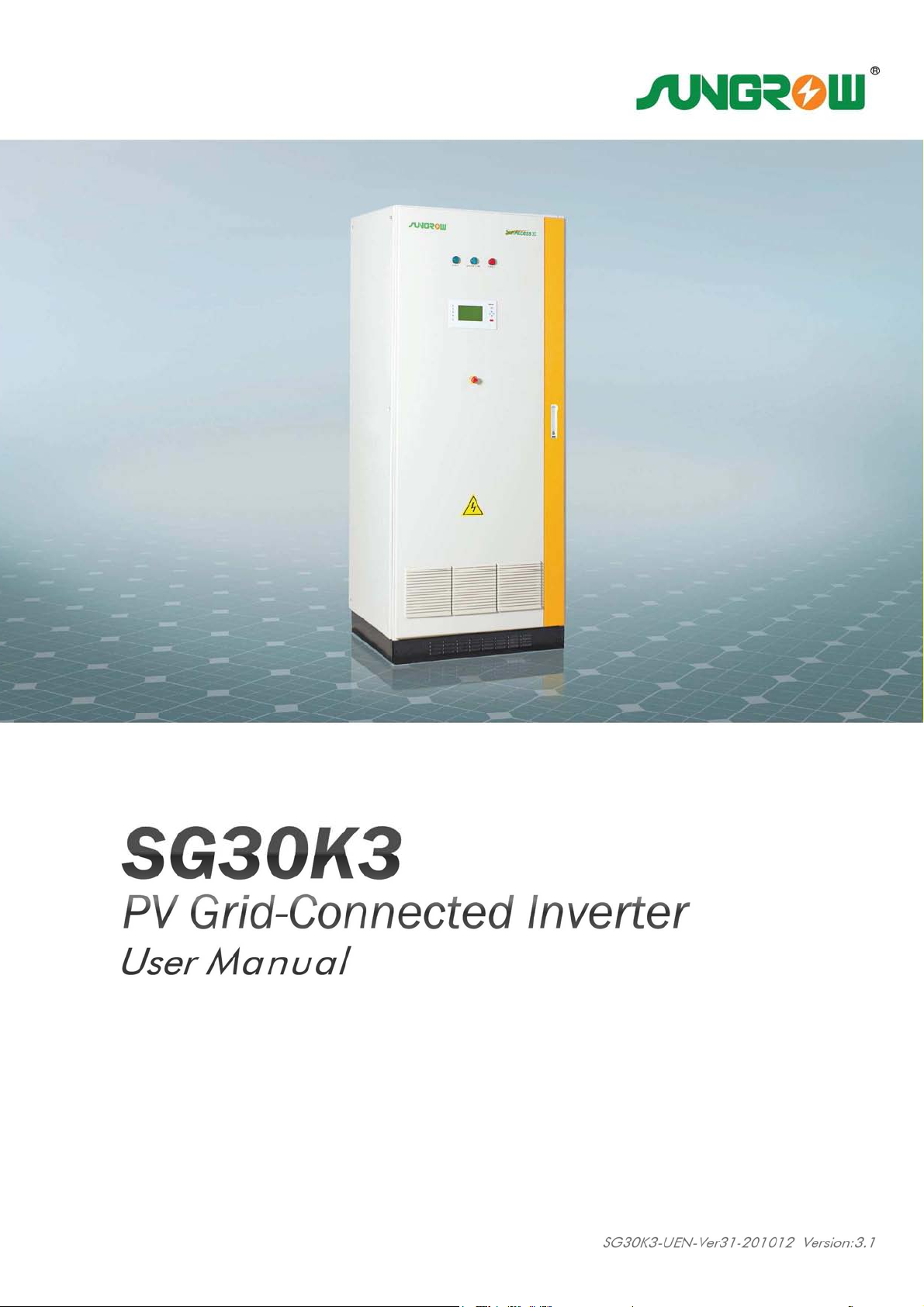
SG30K3 PV Grid-Connected Inverter
User Manual
Sungrow Power Supply Co., Ltd.
All rights reserved
SG30K3-UEN-Ver31-201012 Version: 3.1
Page 2

Page 3

About This Manual
Thank you for purchasing the SG30K3 from Sungrow Power Supply Co., Ltd.. We
hope that the device will meet with your satisfaction when you use it with your PV
plant system.
Aim
The purpose of this manual is to provide users with detailed product information and
instructions for the use of the SG30K3 PV grid-connected inverter.
Target Readers
The manual is provided to people who need to install and operate the SG30K3 grid
connected inverter.
How to Use this Manual
Read this manual and the other documents, before installation and operation on the
SG30K3.
The document must be stored carefully and available at all times.
The contents of this manual will be periodically updated or revised if necessary.
However discrepancies cannot be excluded. Please make the object as the standard
or download the latest version of this manual via www.sungrowpower.com.
I
Page 4
IMPORTANT SAFETY INSTRUCTIONS
IMPORTANT SAFETY INSTRUCTIONS
IMPORTANT SAFETY INSTRUCTIONSIMPORTANT SAFETY INSTRUCTIONS
SAVE THESE INSTRUCTIONS
SAVE THESE INSTRUCTIONS
SAVE THESE INSTRUCTIONSSAVE THESE INSTRUCTIONS
Symbols Explanation
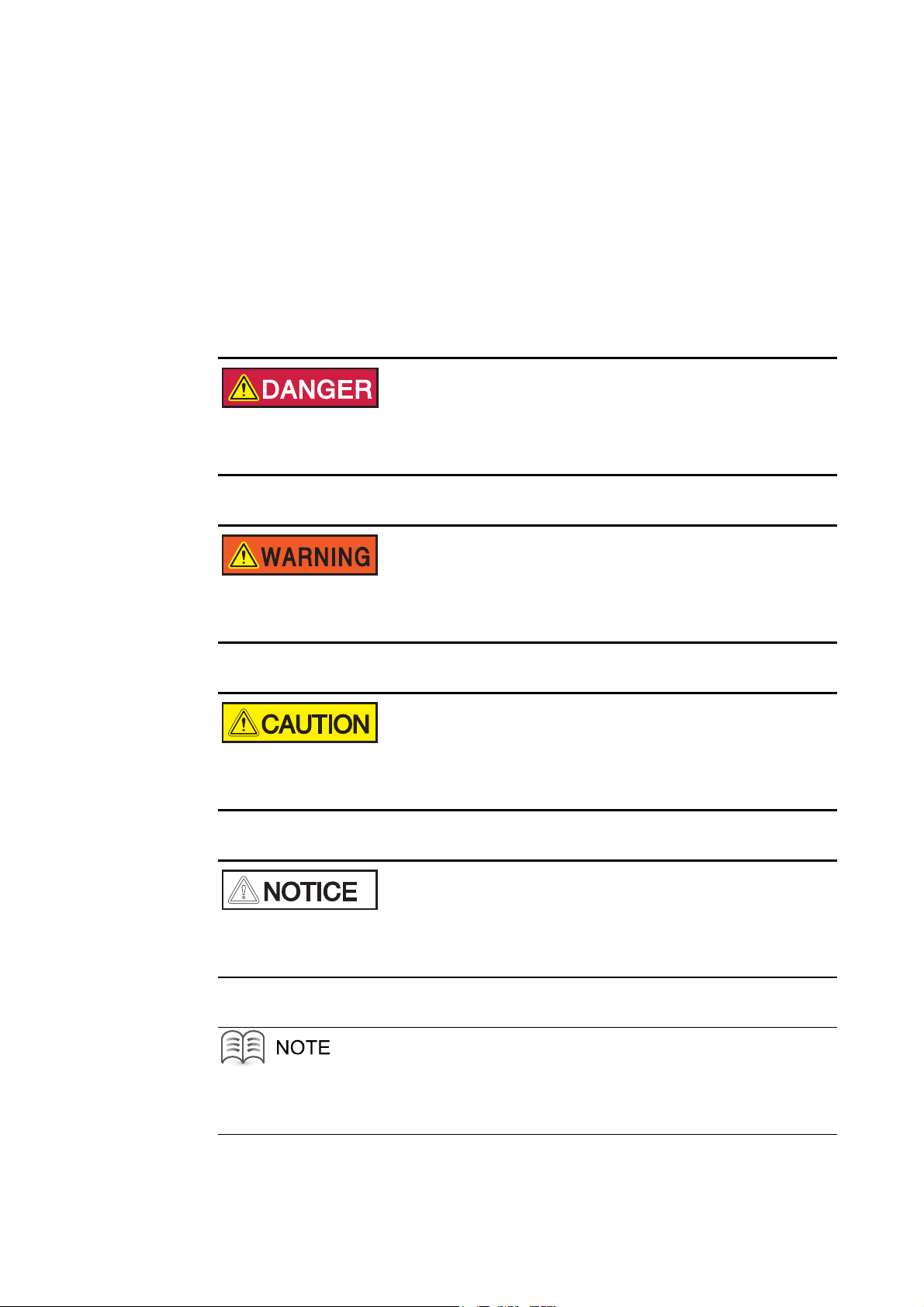
Please note the following explanation of the symbols used in this manual.
DANGER indicates a hazard with a high level of risk which, if not avoided, will
result in death or serious injury.
WARNING indicates a hazard with a medium level of risk which, if not avoided,
could result in death or serious injury.
CAUTION indicates a hazard with a low level of risk which, if not avoided, could
result in minor or moderate injury.
NOTICE indicates a situation which, if not avoided, could result in equipment
abnormal or property damage.
NOTE indicates additional information, emphasized contents or tips to help you solve
problems or save time.
II
Page 5

Contents
1 Safety Instructions .................................................................................................1
2 Introduction.............................................................................................................5
2.1 Grid-Connected PV Inverter .............................................................................................................6
2.2 Circuit Description.............................................................................................................................7
2.3 Scope of Delivery..............................................................................................................................7
2.4 The Wiring Interface .........................................................................................................................8
3 Operation Description...........................................................................................9
3.1 Operation Modes ............................................................................................................................10
3.2 Modes Transition .............................................................................................................................11
3.3 Emergency Stop Button..................................................................................................................12
4 Monitoring and Data Interface..........................................................................13
4.1 Basic Communications ...................................................................................................................14
4.2 LED Indicators ................................................................................................................................15
4.3 LCD Control Panel..........................................................................................................................16
4.3.1 Explanation of the Display Symbols.......................................................................................17
4.3.2 The Total Display Menu.......................................................................................................... 18
4.3.3 Additional Explanation of the LCD Menu................................................................................19
4.3.4 The Default Display Menu...................................................................................................... 20
4.3.5 Check Running Parameters................................................................................................... 21
4.3.6 Check Fault Records..............................................................................................................23
4.3.7 Start the Inverter.....................................................................................................................24
4.3.8 Stop the Inverter.....................................................................................................................25
4.3.9 Enter the Password................................................................................................................ 26
4.3.10 Change Display Language ................................................................................................... 27
4.3.11 Change Date and Time......................................................................................................... 28
4.3.12 Output Energy Value Adjustment ......................................................................................... 29
4.3.13 Load Default Setting............................................................................................................. 31
4.3.14 Displayed Real-time Parameters Adjustment.......................................................................32
4.3.15 Communication Parameters Setting.....................................................................................33
III
Page 6

5 Installation.............................................................................................................35
5.1 Safety Mounting Instructions ..........................................................................................................36
5.2 Checking for Shipping Damage......................................................................................................37
5.3 Basic Installation Requirements .....................................................................................................37
5.4 Mechanical Mounting......................................................................................................................38
5.4.1 Device Dimensions and Weight .............................................................................................38
5.4.2 Moving SG30K3 ..................................................................................................................... 38
5.4.3 Fastening the Unit to the Floor............................................................................................... 39
5.5 Electrical Connection...................................................................................................................... 40
5.5.1 Electrical Connection Requirements...................................................................................... 40
5.5.2 Wires Connection................................................................................................................... 41
5.6 Communication Installation.............................................................................................................43
6 Installation Checklist...........................................................................................45
7 Commissioning.....................................................................................................47
7.1 Requirements of Commissioning....................................................................................................48
7.2 Inspection before Start-up...............................................................................................................48
7.2.1 PV Array Check......................................................................................................................48
7.2.2 SG30K3 Check.......................................................................................................................48
7.2.3 Ground Connection Check..................................................................................................... 48
7.2.4 Serial Communication Check (Optional)................................................................................ 49
7.2.5 Voltages Check ......................................................................................................................49
7.3 Start the Inverter............................................................................................................................. 49
7.4 Complete the Commissioning.........................................................................................................50
8 Operation ...............................................................................................................51
8.1 Start the Inverter............................................................................................................................. 52
8.2 Stop the Inverter .............................................................................................................................52
9 Maintenance ..........................................................................................................53
10 Troubleshooting .................................................................................................57
10.1 LED Indicated Fault Troubleshooting............................................................................................58
10.2 LCD Displayed Fault Troubleshooting .......................................................................................... 59
11 Appendix..............................................................................................................61
11.1 Technical Data...............................................................................................................................62
11.1.1 Electrical Specifications........................................................................................................62
11.1.2 Mechanical Specifications .................................................................................................... 63
11.1.3 System..................................................................................................................................63
IV
Page 7

11.1.4 Display and Communication.................................................................................................63
11.2 Exclusion of Liability......................................................................................................................64
11.3 About Us........................................................................................................................................ 65
V
Page 8

VI
Page 9

1 Safety Instructions
About This Chapter
Safety Instructions
Safety InstructionsSafety Instructions
This chapter provides some important safety instructions about SG30K3.
1
Page 10
SG30K3 User Manual
Pay attention to the following safety instructions:
Shock Hazard!
Death results from burning and electric shock upon touching the SG30K3 live
components.
Do not touch the live components of the SG30K3.
Observe all safety regulations.
Shock Hazard!
The enclosure of SG30K3 inverter may contain high voltage conductors. The
enclosure doors should be kept locked during operation, except for
maintenance or testing.
To avoid the risk of electric shock, do not perform any action or operation
which is not included in the operating instructions unless you are qualified to
do so.
Shock Hazard!
The SG30K3 Inverter will immediately shutdown if users want to open the front
door during operation.
Please check the unit is thoroughly shut down and isolated from the public grid
and PV arrays before open the front door.
To avoid the risk of electric shock, a minimum 5 minutes is needed for any
stored potentials that still left in the inverter after shut-down to be discharged
before opening the door.
2
Page 11
Safety Instructions 1
Lethal Voltage!
Damage to the SG30K3 may result death by electric shock or fire!
Only operate SG30K3 when it is safe to do so!
Only operate SG30K3 when no damage is visibly apparent!
DC Voltage!
The PV array will provide DC voltage to the inverter when exposed to light,
which may cause an electrical shock during installation, wiring or maintenance
if not covered.
Limitation of Use!
The SG30K3 Grid-Connect Photovoltaic Inverter is not intended for use in
connection with life support systems or other medical equipment or devices.
ESD Protection!
The SG30K3 may be damaged irreversibly by electrostatic discharge (ESD) at
its components.
During the operation of SG30K3, please observe all the ESD related safety
regulations!
Discharge any ESD by touching the grounded SG30K3 conductor before
contacting any electronic components!
3
Page 12
SG30K3 User Manual
Service Safety!
Thoroughly inspect the equipment prior to energizing. Verify that no tools or
equipment have inadvertently been left behind.
Never work alone when servicing this equipment. Two persons are required
until the equipment is properly de-energized, locked out and verified
de-energized with a meter.
Please keep this installation manual and other related document in the handy place of
the SG30K3.
These documents must be available to operators and maintenance personnel at all
times.
4
Page 13

2 Introduction
About This Chapter
Introduction
IntroductionIntroduction
This chapter provides basic information about SG30K3.
5
Page 14
SG30K3 User Manual
2.1
Grid
Grid----Connected PV
GridGrid
Connected PV IIIInverter
Connected PV Connected PV
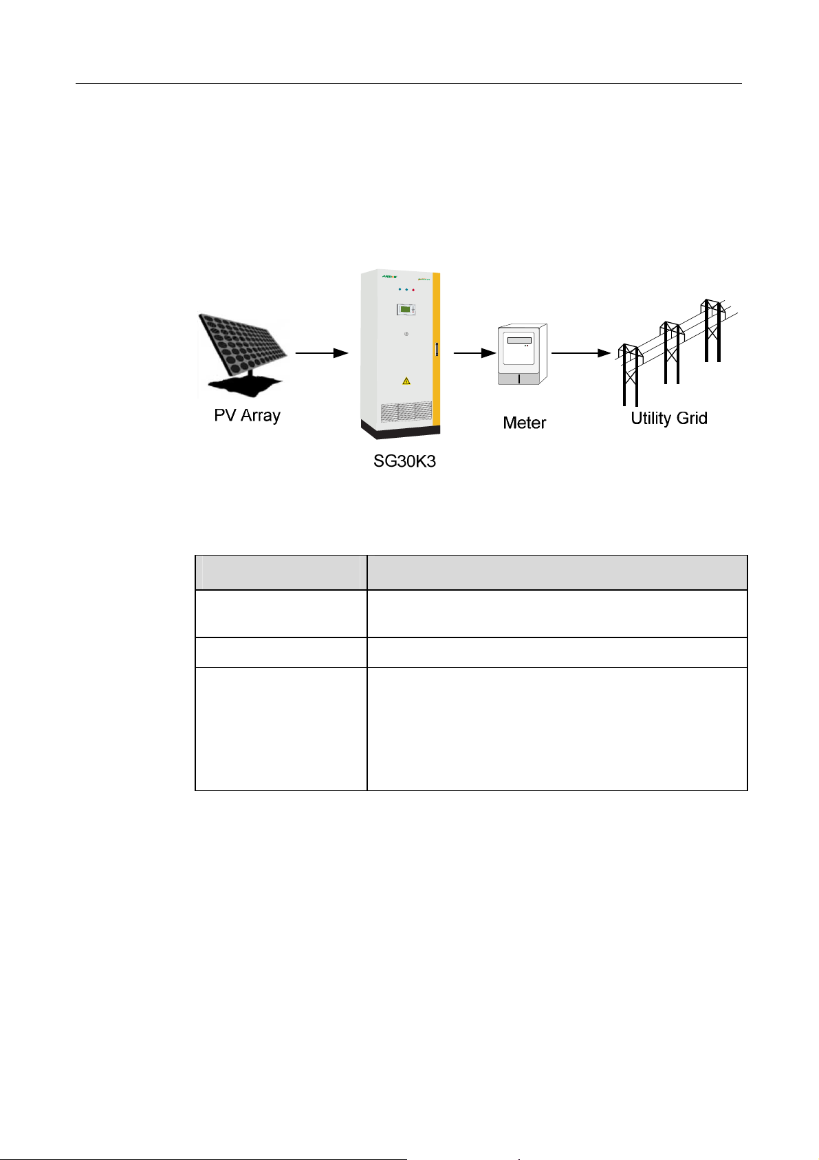
A SG30K3 grid-connected PV system is shown in Fig 2-1. SG30K3 transforms the
direct current generated by the PV array into stable alternating current and output to
the utility grid.
nverter
nverternverter
Fig 2-1 Grid-connected Inverter for PV Power Application
Table 2-1 System Devices Type
Device Type
PV Arrays Monocrystalline Silicon, Polycrystalline Silicon, Amorphous Silicon,
Thin Film Cells
Utility Grid TT, TN-C, TN-S, TN-C-S, IT
Optional Devices SunInfo EM Environment Monitoring Device
SunBox PVS PV Array Combiner Box
SunBox PMD-D DC Power Distribution Cabinet
SunBox PMD-A AC Power Distribution Cabinet
SunInfo Logger Inverter Data Acquisition and Transmission Device
6
Page 15
2.2
Circuit Description
Circuit Description
Circuit DescriptionCircuit Description
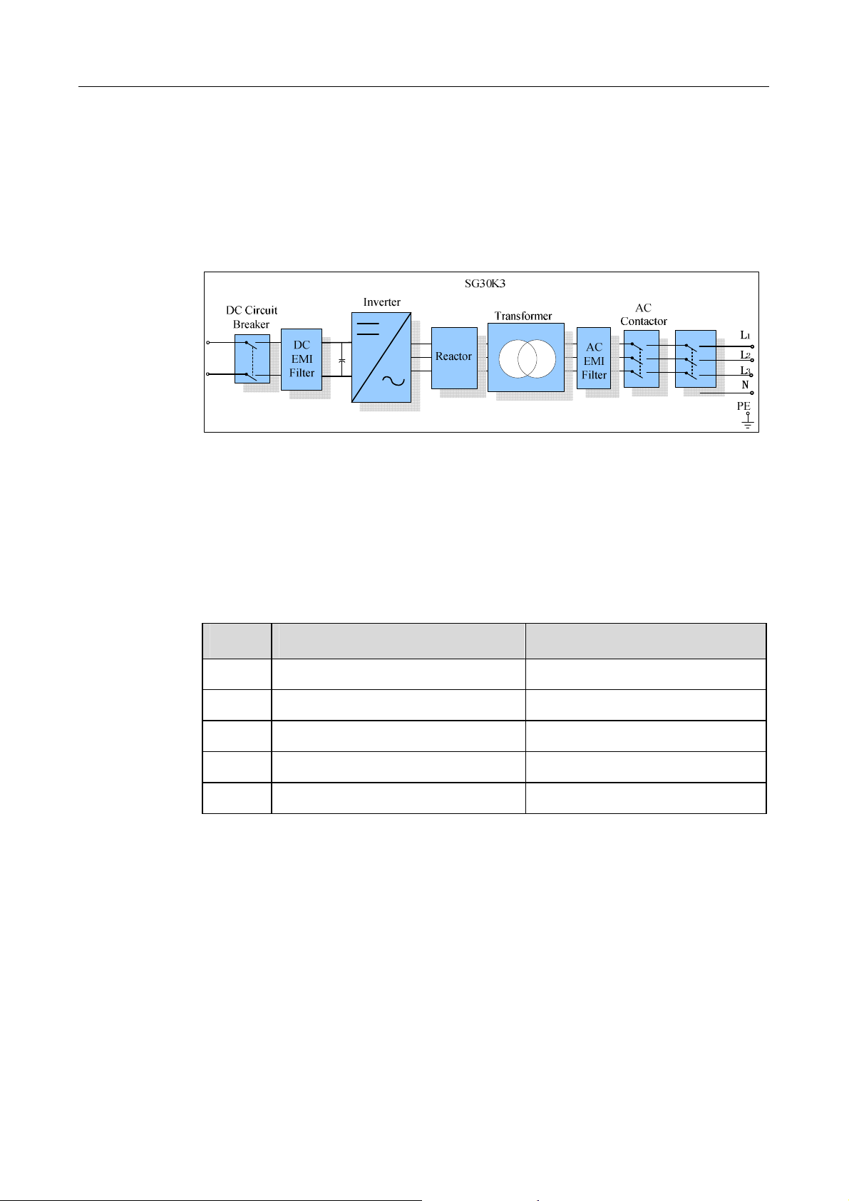
Fig 2-2 shows the main circuit of SG30K3 -a transformer grid-connected inverter. An
IGBT full-bridge converts the DC power to AC voltage and current. The AC power is
then fed to the grid after being processed by a filter and a transformer.
Introduction 2
Fig 2-2 Main Circuit Diagram of SG30K3
2.3 Scope of Delivery
Scope of Delivery
Scope of DeliveryScope of Delivery
The following materials in Table 2-2 should including in the crate.
Table 2-2 Scope of Delivery
No. Name Note
1 SG30K3 PV Grid-Connected Inverter Including keys
2 SG30K3 User Manual 3 Warranty Card 4 Certificate of Quality 5 Product Test Report -
7
Page 16
SG30K3 User Manual
2.4
The Wiring
The Wiring Interface
The Wiring The Wiring
Interface
InterfaceInterface
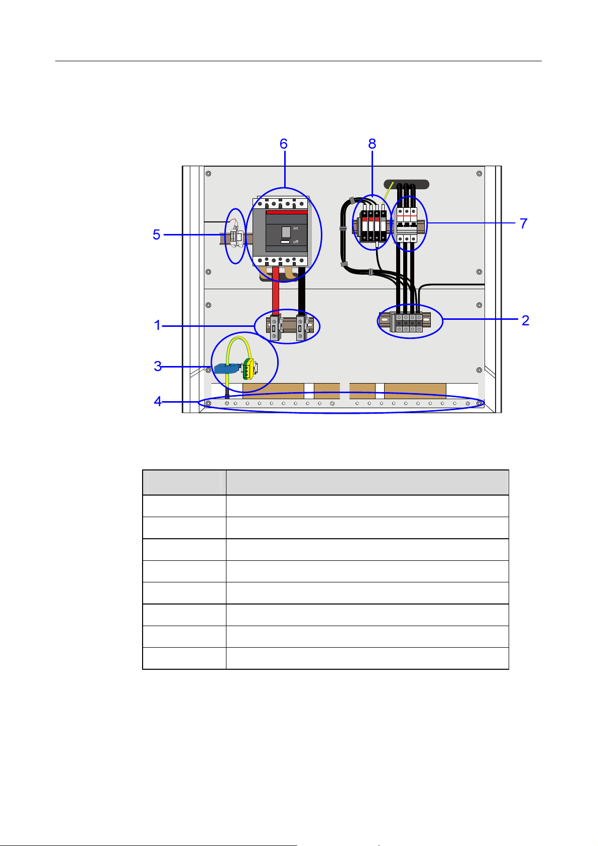
Fig 2-3 The Wiring Interface of SG30K3
Table 2-3 Terminal Descriptions
Terminal No. Description
1 DC INPUT: Connected to the PV array
2 AC OUTPUT: L1,L2,L3,and N
3 Ground Terminal: Leaking current detector
4 GND: ground copper bar
5 RS485 A/B serial communication port
6 DC Circuit Breaker
7 AC Circuit Breaker
8 Lightning Protector
8
Page 17

3 Operation Description
About This Chapter
Operation Description
Operation DescriptionOperation Description
SG30K3 inverter is a fully automated grid-connected solar inverter with friendly user
interface. This chapter provides instructions about how to operate the SG30K3.
9
Page 18

SG30K3 User Manual
3.1
Operation Modes
Operation Modes
Operation Modes Operation Modes
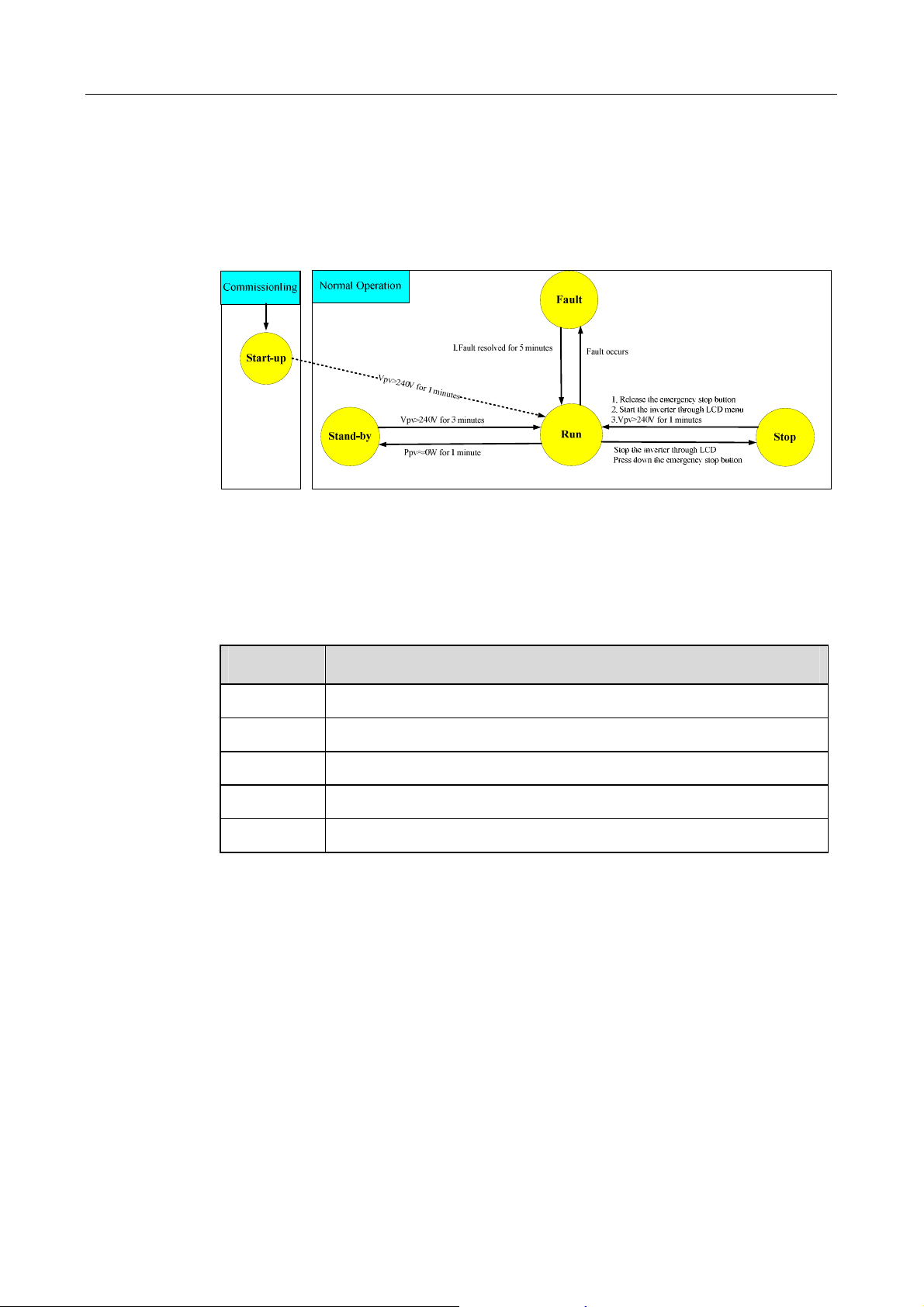
The modes displayed in the LCD interface include: “Start-up”, “Stand-by”, “Run”,
“Fault” and “Stop”. Their explanations are given below.
Once the AC and DC connections are OK, all the parameters meet requirements,
the AC and DC breaks are closed, The inverter will auto start.
If the input voltage is below the start voltage 240V, the inverter keeps in
“Start-up” state.
If the input voltage exceeds 240V, and holds the value for 1 minute, the inverter
is ready for operation; it begins feeding power to the grid and the state changes
from “Startup” to “Run”.
Standby-mode is entered for insufficient input power (Ppv≈0 for 1 minute), at
stand-by mode the inverter will wait until the DC voltage recovers to 240V for 3
minutes.
Start-up
Stand-by
Run
After being energized, the inverter tracks the PV arrays’ maximum power point
(MPP) and converts the DC power to AC power.
Fault
If a fault occurs during operation, the SG30K3 will automatically stop operation,
disconnect the AC contactor and the display the fault type in the LCD panel with
the “Fault” LED burns.
Once the fault is removed for 5 minutes, the SG30K3 will automatically resume
running.
Stop
The SG30K3 will stop operation by manually stopping the inverter through LCD
menu or pressing down the “Emergency Stop Button”, this condition needs
manual restart through LCD menu.
During the “Stop” mode, the SG30K3 will block the driving signals that control the
switching IGBT and disconnect the SG30K3 from the grid by switching off the AC
contactor.
10
Page 19
3.2
Modes Transition
Modes Transition
Modes TransitionModes Transition
When energized, the inverter switches states from different modes as pictured below.
When deactivated, the inverter return to the operating mode "Stop".
Operation Description 3
Fig 3-1 Transition of operation states
*VPV is the DC input voltage; Ppv is the DC input power
The states displayed in the LCD menu are explained in the table below.
Table 3-1 State explanations of inverter
LED state Explanation
RUN The inverter is in operation and output power to the grid
STOP The operation is stopped by stop command
Start-up The inverter is under activation
Stand-by The operation is ceased by insufficient PV power
*Fault type A fault is occurred and not solved
*the characters “Fault type” itself will not be displayed during a fault condition, but the
real fault type will be displayed like “Vdc-high” or “Vac-low” etc.
The “Com-flt” shows that there is a fault between LCD and DSP, which also means
that users cannot check or set parameters through LCD control menu during this fault.
But this fault will not stop the inverter, which is different from Fault condition.
11
Page 20
SG30K3 User Manual
3.3
Emergency Stop Button
Emergency Stop Button
Emergency Stop ButtonEmergency Stop Button
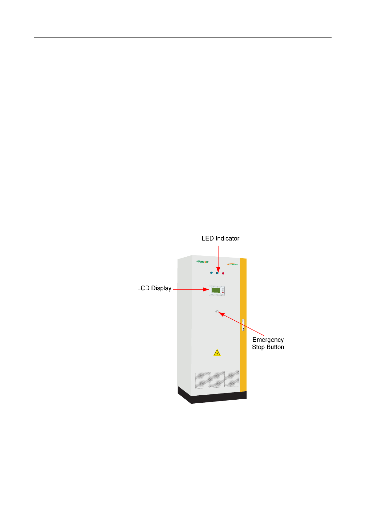
The Emergency stop button will shutdown the inverter (disconnect the AC contactor)
immediately when it is punched (pressed down).
The inverter must be started up manually through LCD control menu if users want to
recover the operation after the button is punched.
How to Restart the Inverter after Using the Emergency Stop Button:
Users must manually restart the inverter according to the following procedure when
the operation of the SG30K3 is stopped by punching the emergency stop button:
1. Turn the emergency stop button clockwise to release the inverter from the
stop state.
2. Perform the stop command in the LCD menu.
3. Perform the start command in the LCD menu.
4. Then the inverter will restart.
Fig 3-2 Emergency stop button
12
Page 21

4 Monitoring and Data Interface
About This Chapter
Monitoring and Data Interface
Monitoring and Data InterfaceMonitoring and Data Interface
This chapter provides instructions about monitoring and data Interface of the SG30K3.
13
Page 22
SG30K3 User Manual
4.1
Basic Communications
Basic Communications
Basic CommunicationsBasic Communications
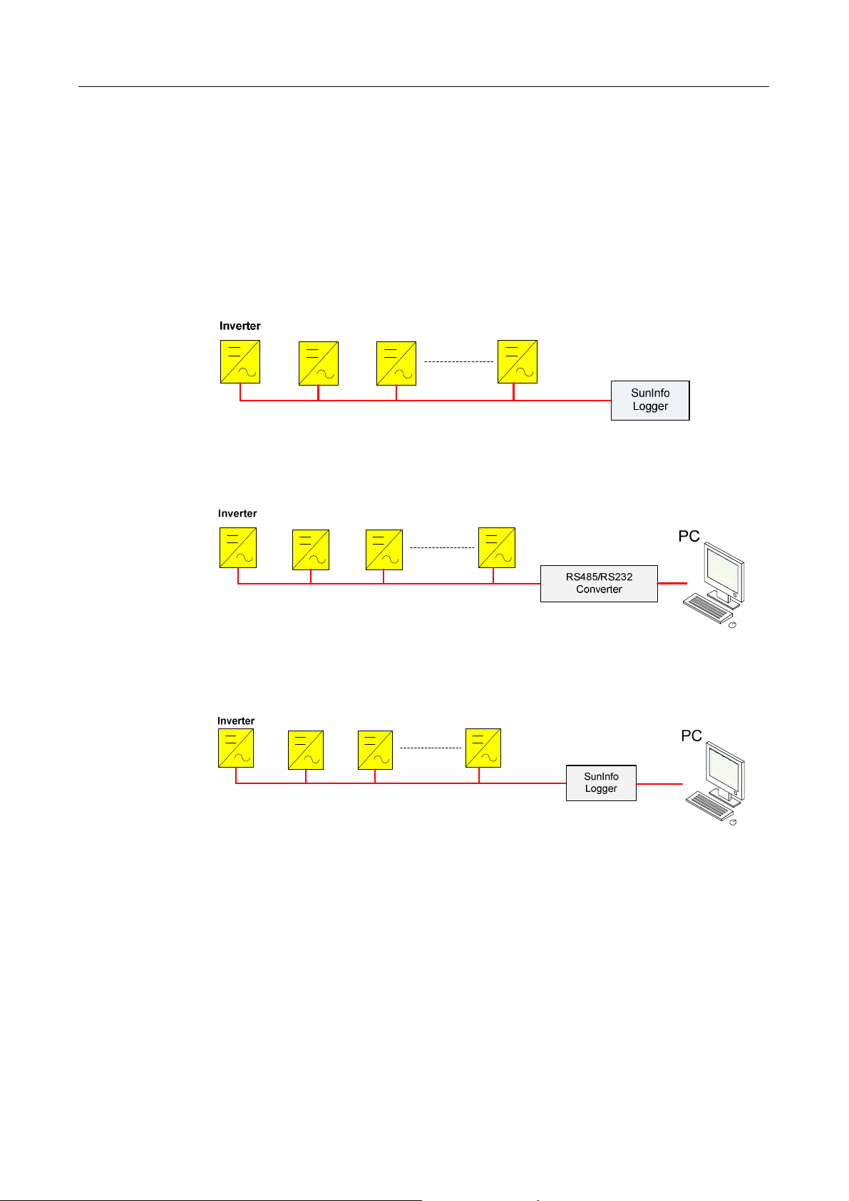
To enable our customers to gain a thorough comprehension about the operation of the
inverter, we have provided various data-collection approaches to monitor system
data.
Data logger
PC
Fig 4-1 Data Logger Collects Data through RS485 Bus
Data logger + PC
Fig 4-2 PC Collects Data through RS485 Bus
Fig 4-3 Data Logger & PC Collects Data through RS485 Bus
14
Page 23
4.2
LED Indicators
LED Indicators
LED IndicatorsLED Indicators
Monitoring and Data Interface 4
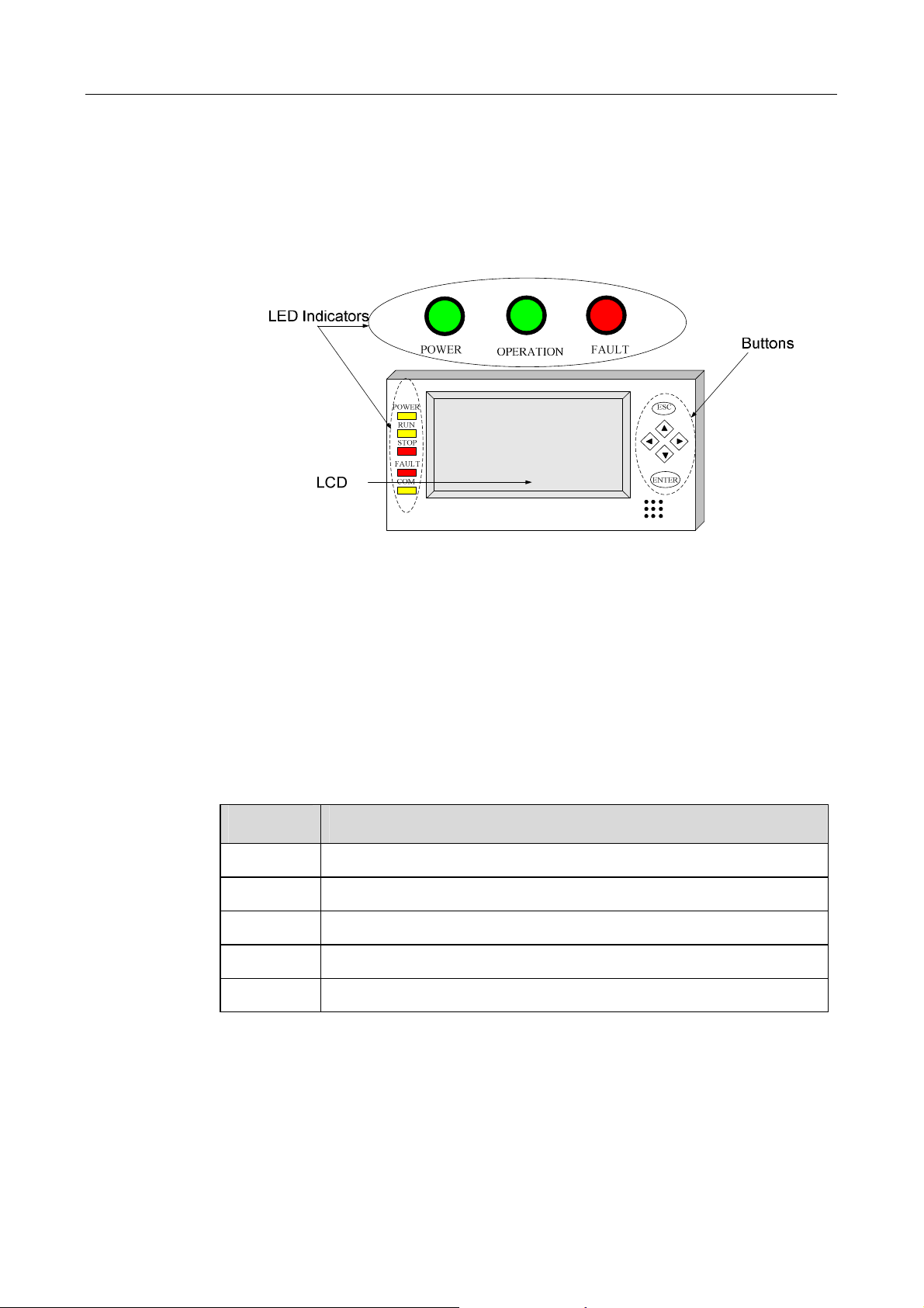
Users can get the running data and set parameters of SG30K3 from the LED
indicators and LCD control panel, see Fig 4-4.
Fig 4-4 SG30K3 data interface
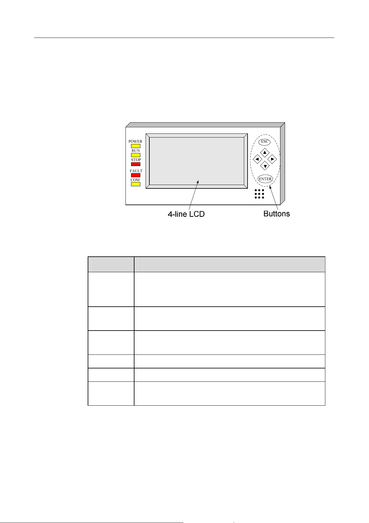
3 big LED indicators are located in the front door of SG30K3 and 5 smaller LED
indicators in the LCD panel.
These LED indicators help the users to quickly learn about the states of the SG30K3
inverter. Check Table 4-1 for their definitions.
Note that the big “POWER” ,”OPERATION” and “ FAULT” LED indicators share the
same meaning with small “POWER”,”RUN” and “FAULT” indicators.
Table 4-1 Meaning of LED indicators
LED name Explanation
POWER The indication of control board’s power supply
RUN Inverter is in grid mode and working normally
STOP When the SG30K3 stops operation
FAULT There is a fault in the power system
COM Communication indication between inverter and PC
15
Page 24
SG30K3 User Manual
4.3
LCD Control Panel
LCD Control Panel
LCD Control PanelLCD Control Panel
The LCD control panel is mounted on the SG30K3 enclosure at eye level.
6 buttons right next to the LCD are used to check or set parameters in the LCD control
menu, see Fig 4-5.
Fig 4-5 LCD panel
Table 4-2 Definitions of buttons
Button Function
ESC cancels / ends the present function
answers questions with "No"
returns to the previous menu
▲ moves up to the previous line
increases the present value
▼ moves down to the next line
decreases the present value
► moves to the right value
◄ moves to the left value
ENTER selects a function from the menu
selects a value/confirms changes/answers questions with "Yes"
The background illumination of the LCD is activated by pressing any button on the
panel and will automatically be deactivated 2 minutes later to save power.
16
Page 25
Monitoring and Data Interface 4
4.3.1 Explanation of the Display Symbols
Explanation of the Display Symbols
Explanation of the Display SymbolsExplanation of the Display Symbols
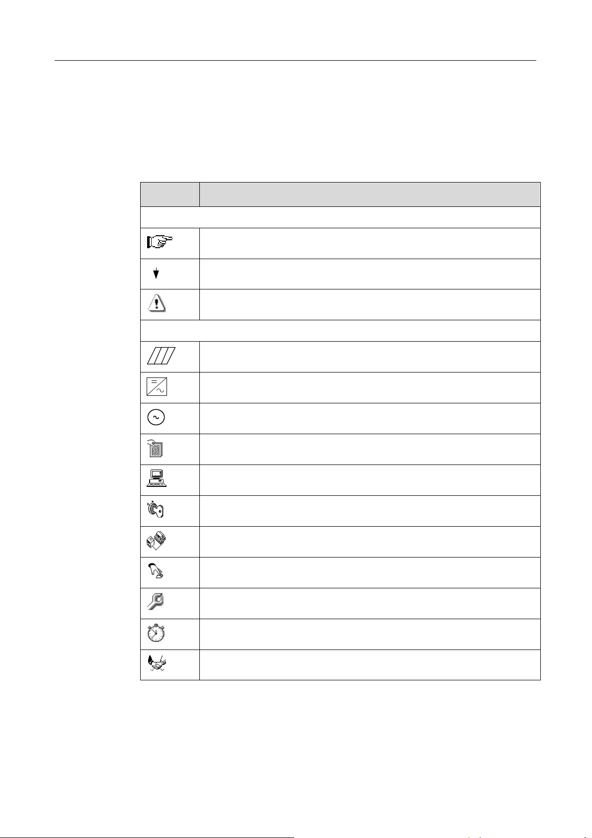
The SG30K3 display has four lines. Multiple display symbols are used, which are
explained in the following Table 4-3.
Table 4-3 Explanations of symbols used in the control menu
Symbol Explanations
General Symbols
There is sub-level menu. Press “Enter” to move to next menu
There are more display menus below. Press “↓” to move to next menu
This menu indicates some information needed to be care about
Specific Symbols
The PV array
The Inverter
One phase of the grid
This menu displays data
General control menu.
Control the start/stop of the inverter.
Communication parameters setting menu
Energy adjustment menu
General parameter menu
Time setting menu
Language setting menu
17
Page 26
SG30K3 User Manual
4.3.2 The Total Dis
The Total Display Menu
The Total DisThe Total Dis
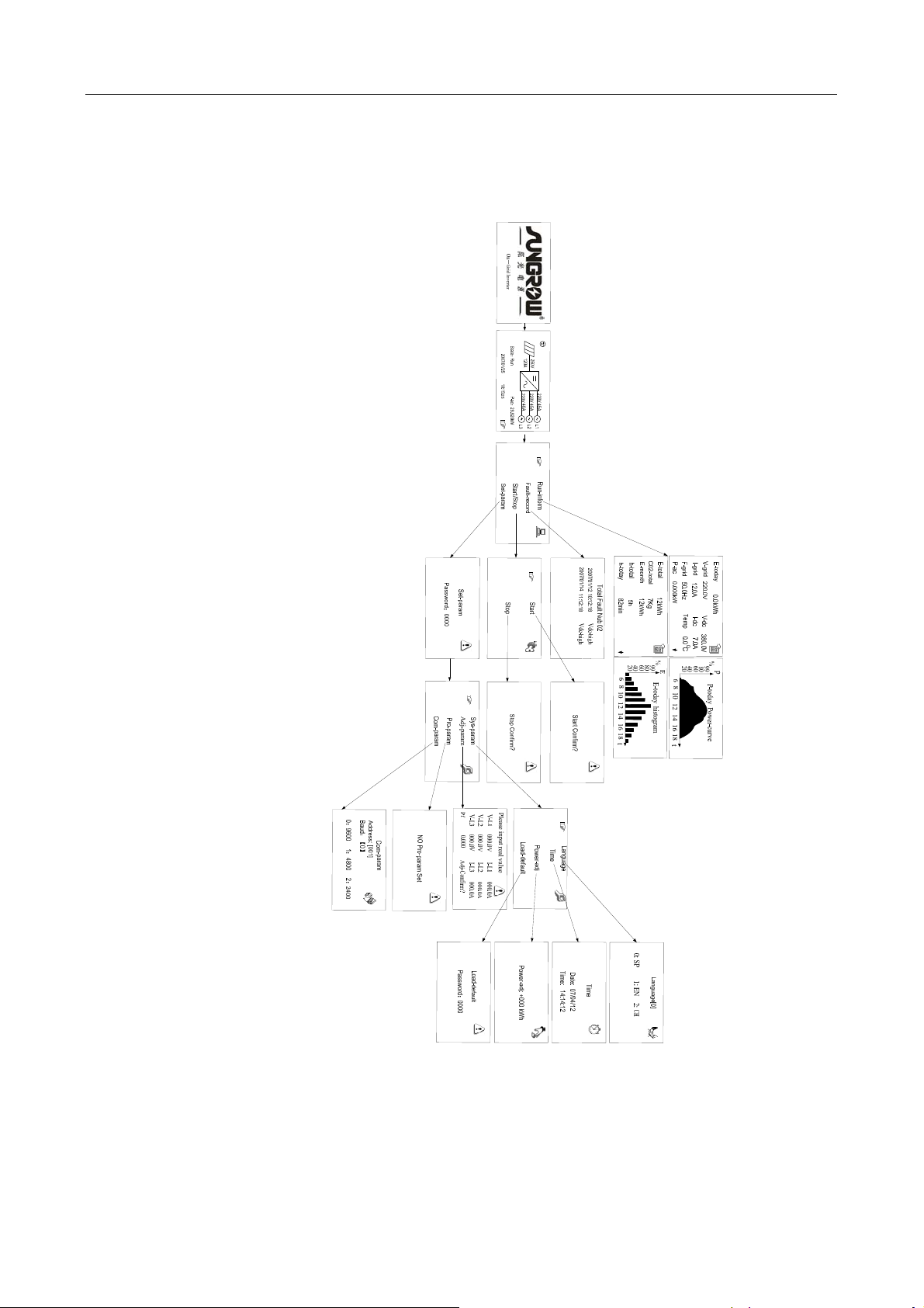
The total display menu is given in the Fig 4-6 below.
play Menu
play Menuplay Menu
Fig 4-6 Total display menu tree
18
Page 27
Monitoring and Data Interface 4
4.3.3 Additional Explanation of the LCD Menu
Additional Explanation of the LCD Menu
Additional Explanation of the LCD MenuAdditional Explanation of the LCD Menu
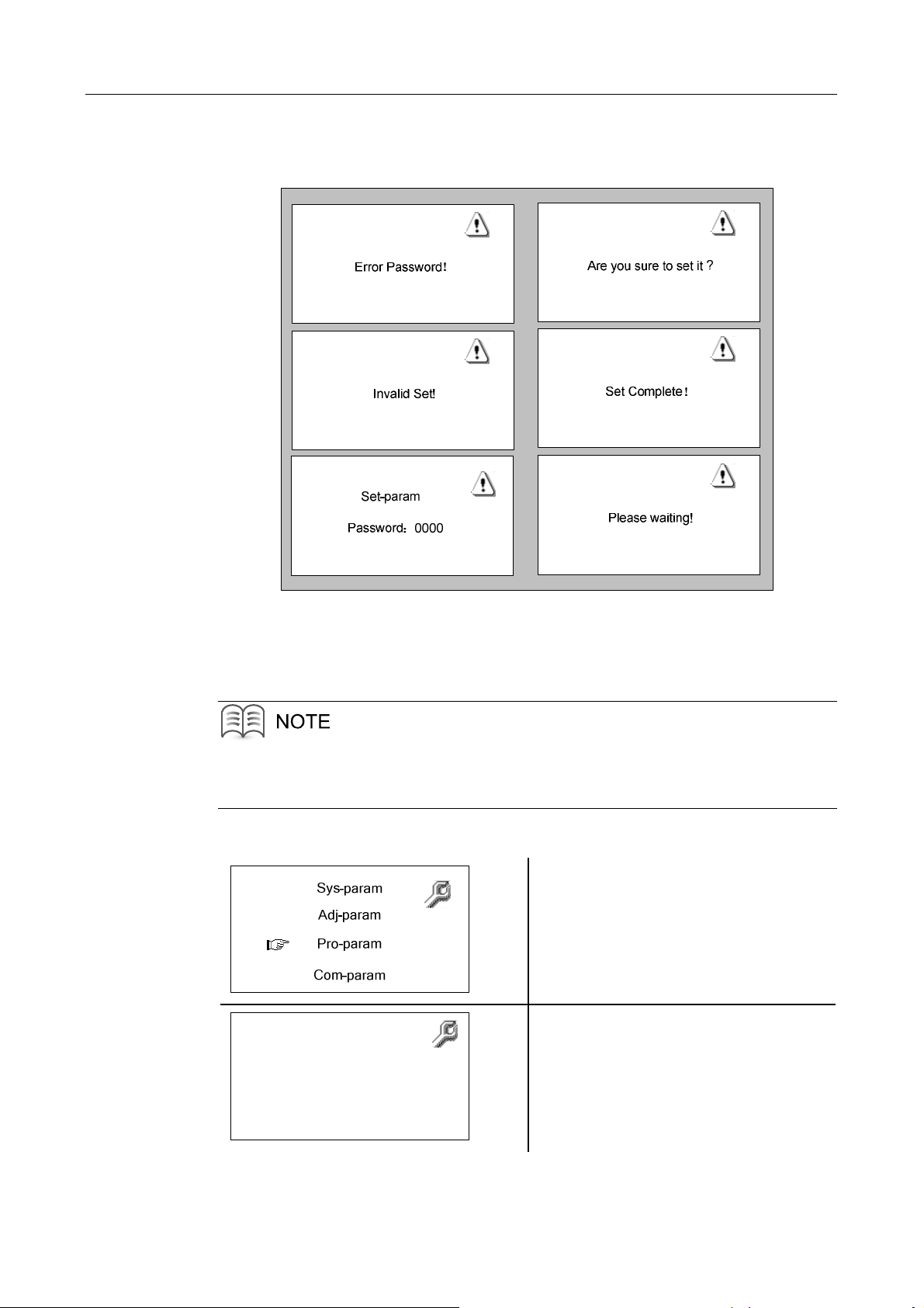
Fig 4-7 Prompting message menu
Fig 4-7 shows all the prompting messages not included in the total display menu but
will be displayed in the LCD.
“Pro-param” menu contains no valid setting; it is kept for future protection parameters
adjustment.
1. Select “Pro-param”
2. Press “ENTER”
3. No protection parameters can be
set or adjusted
NO Pro-param Set
19
Page 28
SG30K3 User Manual
4.3.4 The Default Display Menu
The Default Display Menu
The Default Display MenuThe Default Display Menu
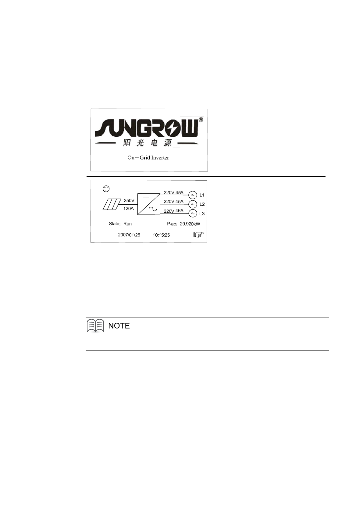
The LCD is initializes upon energized of the SG30K3. A starting menu will be
displayed during initialization, which shows the manufacture name and the type of the
inverter.
1. The initialization menu
Only appear once after activation
2. The Default menu
Display basic running parameters
Once the LCD is initialized for about 2-3 minutes, it will automatically changes to the
default menu. In the default menu, the basic real-time running values are displayed,
which includes DC current and DC voltage, the AC phase current and AC
line-to-neutral voltage, the operation state, the output AC power and the system
time and date.
Fault type will be displayed in the “State” of the default menu when a fault occurs.
20
Page 29
Monitoring and Data Interface 4
4.3.5 Check Running Parameters
Check Running Parameters
Check Running ParametersCheck Running Parameters
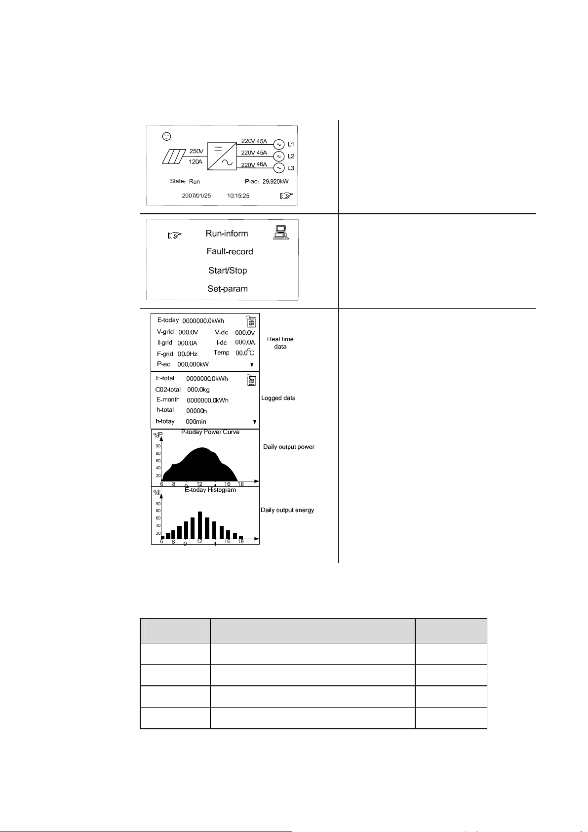
1. In the default menu.
2. Press “ENTER” or “►” to enter the
general control menu
3. Navigate the hand-pointer to the
“Run-inform”
4. Press “ENTER” button to access the
sub-menus of running parameters
5. Use “▼” to move among these 4
menus to check parameters.
This level menus contains 4 separate
menus.
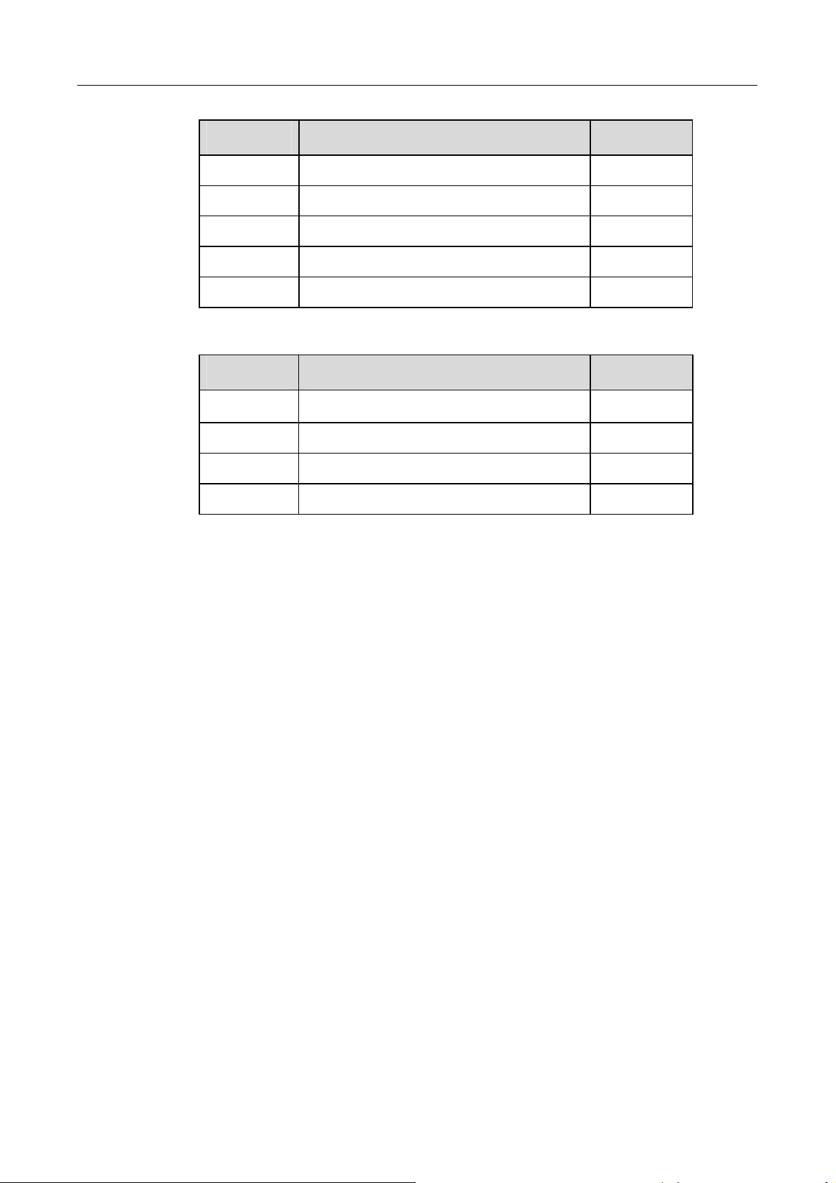
Please refer to Table 4-4 and Table 4-5 for the explanations of displayed running data.
Table 4-4 The Explanation of The Real-time Data
Data name Explanation Unit
V-grid Grid voltage V
I-grid Output AC current A
F-grid Grid frequency Hz
V-dc DC Voltage (of PV array) V
21
Page 30
SG30K3 User Manual
Data name Explanation Unit
I-dc DC Current (of PV array) A
P-ac Output ac power W
E-today Energy generated today kWh
E-month Energy generated this month kWh
E-total The total generated Energy kWh
Table 4-5 Explanation of non-electrical parameters
Data name Explanation Unit
Temp Temperature within the enclosure
h-today The Operation time of today Min
h-total Total hours of Operation time H
CO2-total Reduced CO2 weight kg
℃
The internal logged data includes: total energy generated since the first
start-”E-total”, energy generated within the current month-”E-month”, total
running time in hour-”h-total”, the total running time within today- “h-today”,
and the weight of the CO2 which can be avoided by using the green PV
plant-”CO2-total”.
The real time data includes: daily generated energy “E-today”, the grid voltage
“V-grid”, the grid frequency “F-grid”, the grid current “I-grid”, the DC voltage
“V-grid”, DC current “I-grid”, the inverter’s inside temperature “Temp” and
today’s running minutes “h-today”.
The “P-today power curve” diagram shows the power generated from 6.am to
18.pm in a single day, the data are updated every 3.75 seconds and the total
diagram data will be cleared at the beginning of a new day. The P axis is marked
by the percentage of the rated power 30kW.
The “E-today histogram” diagram shows the energy generated from 6.am to
18.pm in a single day, the data is updated every second and the length of the
block is 1 hour. The total diagram data will be cleared at the beginning of a new
day. The E axis is marked by the percentage of the 30kWh.
22
Page 31
Monitoring and Data Interface 4
4.3.6 Check
Check Fault
CheckCheck
Fault Record
Fault Fault
Recordssss
RecordRecord
2
5
0
V
1
2
0
A
S
t
a
t
e
:
R
u
n
2
0
0
7
/
0
1
/
2
5
2
2
0
V
4
5
A
L
2
2
0
V
4
4
2
2
0
V
P
-
a
c
:
1
0
:
1
5
:
2
5
1
5
A
L
2
6
A
L
3
2
9
.
9
2
0
k
W
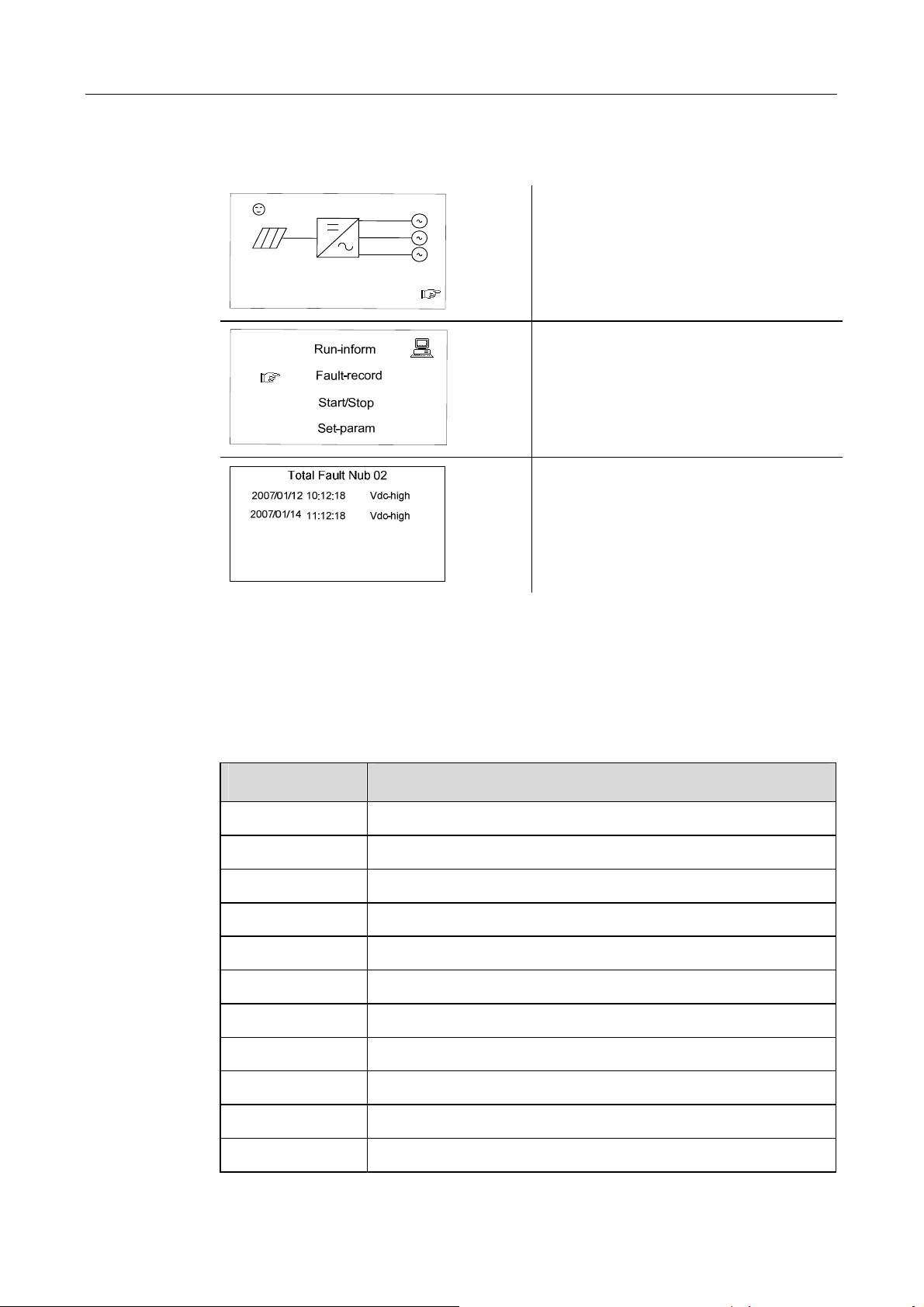
2. Press “ENTER” or “►” to enter the
general control menu
3. Navigate the hand-pointer to the
“Fault-record” and press “ENTER”
button.
1. In the default menu.
4. Navigate the arrow-pointer to the
“Fault-record” and press “ENTER”
button.
The “Fault-record” can log the latest 20 fault records, which includes the fault name
and occurred time.
Note that one screen can only display 7 fault records, press “▼” button to move to
next fault records if necessary.
Table 4-6 Explanations of faults
Fault type Explanation
Vdc-high DC voltage is too high
Vac-high Grid voltage is too high
Vac-low Grid voltage is too low
F-fault Grid frequency is abnormal
Island Island(grid in unavailable)
Dsp-flt The control DSP malfunctions
Ipm-flt The IPM power module malfunctions
Cntr-flt AC side contactor malfunctions
Ttp-high Temperature of the main transformer is too high
Temp-flt Temperature inside the enclosure is too high
Gnd-flt A ground fault is occurred
23
Page 32
SG30K3 User Manual
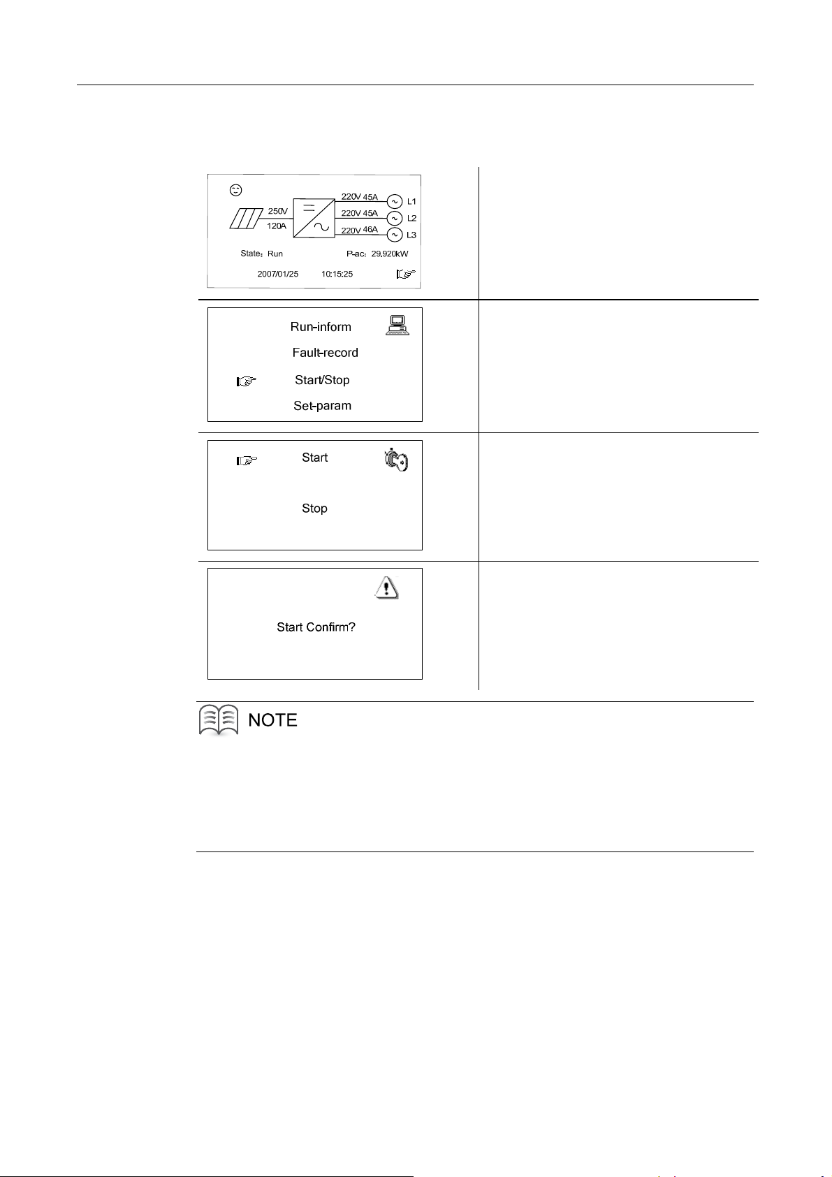
4.3.7 Start the Inverter
Start the Inverter
Start the InverterStart the Inverter
1. In the default menu.
2. Press “ENTER” or “►” to enter the
general control menu
3. Navigate the hand-pointer to the
“Start/Stop” and press “ENTER”
button.
4. Navigate the arrow-pointer to the
“Start” and press “ENTER” button.
5. Press “ENTER” button to confirm
the start command.
Normally the inverter will auto start when specifications are met or faults are removed.
The start function of the control menu is provided in case the inverter needs a restart
after being stopped by pressing down the emergency stop button or perform manual
stop in the LCD menu.
24
Page 33
Monitoring and Data Interface 4
4.3.8 Stop the Inverter
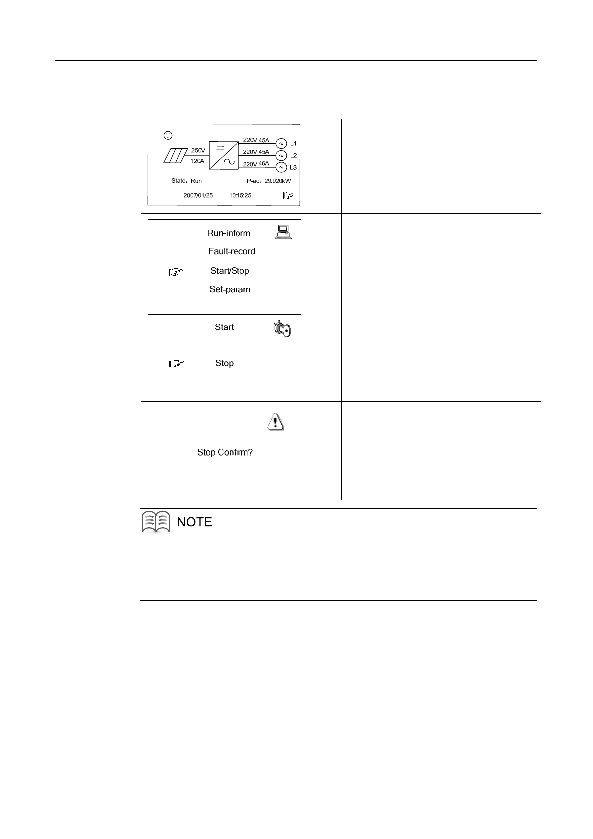
Stop the Inverter
Stop the InverterStop the Inverter
1. In the default menu.
2. Press “ENTER” or “►” to enter the
general control menu
3. Navigate the arrow-pointer to the
“Start/Stop” and press “ENTER”
button.
4. Navigate the arrow-pointer to the
“Stop” and press “ENTER” button.
5. Press “ENTER” button to confirm
the stop command.
To the inverter, the emergency stop button has the same effect as the manual stop
function.
They both disconnect the AC contactor and need manual Start in the LCD menu.
25
Page 34
SG30K3 User Manual
4.3.9 Enter the Password
Enter the Password
Enter the PasswordEnter the Password
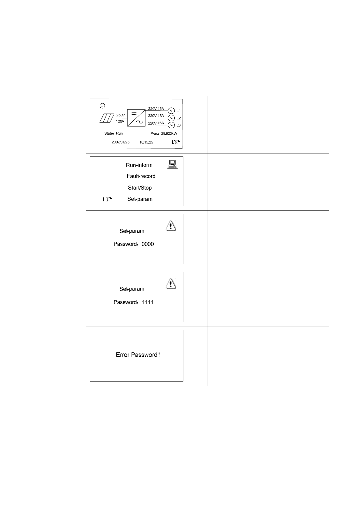
SG30K3 parameters are password protected, which means they can only be adjusted
upon entry of a password. To enter the password, proceed as follows:
1. In the default menu.
2. Press “ENTER” or “►” to enter the
general control menu
3. Navigate the arrow-pointer to the
“Set-param” and press “ENTER”
button.
4. Use “◄”and “►”to choose digits,
employ “▲”and “▼” to increase or
decrease number.
5. Press “ENTER” button to confirm
the password input.
Note that the default password is
1111.
6. NOTE! If the password is not
correct, the hint information “Error
Password!” will display on the LCD.
26
Page 35
Monitoring and Data Interface 4
4.3.10 Change Display Language
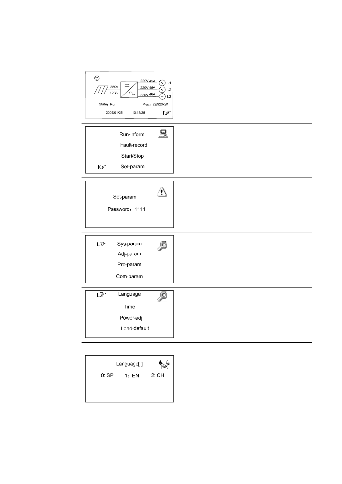
Change Display Language
Change Display LanguageChange Display Language
1. In the default menu.
2. Press “ENTER” or “►” to enter the
general control menu
3. Navigate the arrow-pointer to the
“Set-param” and press “ENTER”
button.
4. Press “ENTER” button to confirm
the password input.
Note that the default password is
1111.
5. Navigate the arrow-pointer to the
“Sys-param” and press “ENTER”
button.
6. Move the arrow-pointer to the
“Language” and press “ENTER”
button.
7. Use “▲”or “▼” to change number
between 0, 1 and 2.
0 represents Spanish and 1 means
English and 2 for Chinese.
Choose the number you want and
press “Enter” to confirm your choice.
27
Page 36
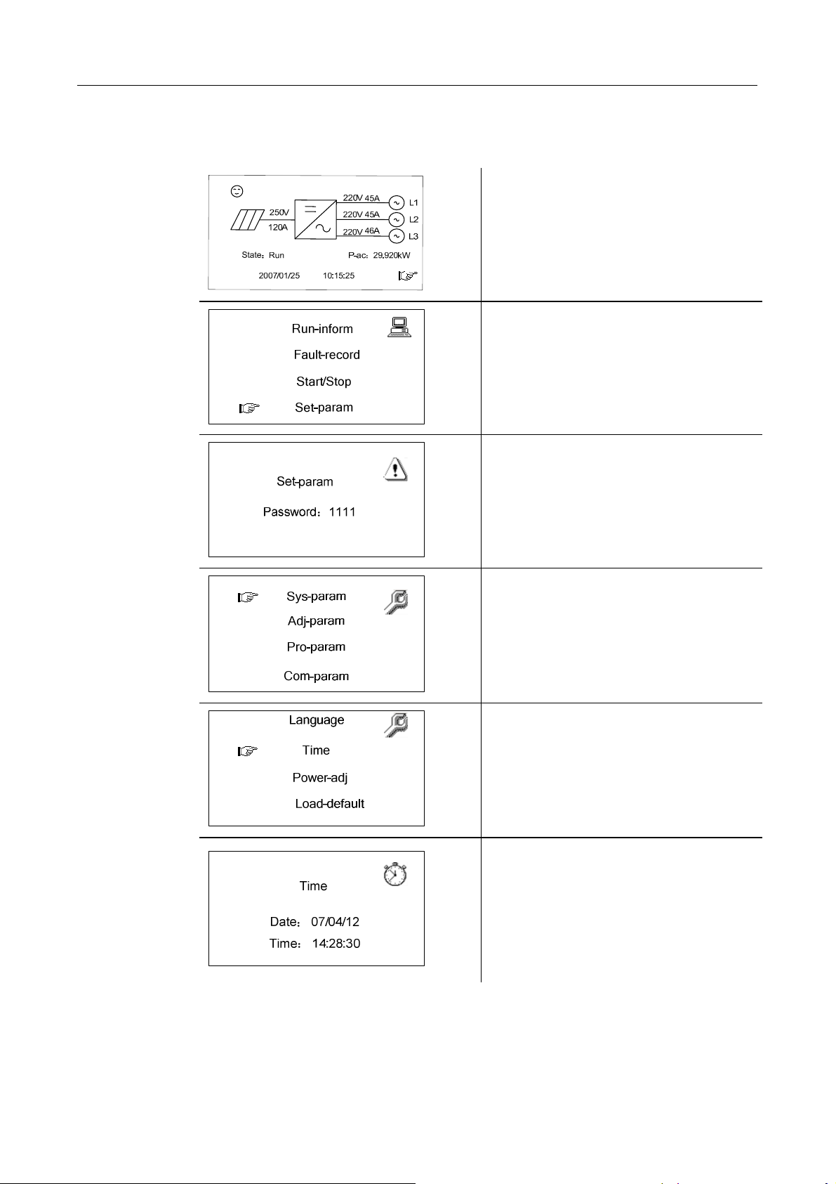
SG30K3 User Manual
4.3.11 Change Date and Time
Change Date and Time
Change Date and TimeChange Date and Time
1. In the default menu.
2. Press “ENTER” or “►” to enter the
general control menu
3. Navigate the hand-pointer to the
“Set-param” and press “ENTER”
button.
4. Press “ENTER” button to confirm
the password input.
Note that the default password is
1111.
5. Navigate the hand-pointer to the
“Sys-param” and press “ENTER”
button.
6. 6. Move the hand-pointer to the
“Time” and press “ENTER” button.
7. Use “◄”and “►”to choose digits,
employ “▲”and “▼” to increase or
decrease number.
8. Input the number you want
according to your local time and
press “Enter” to confirm them.
28
Page 37
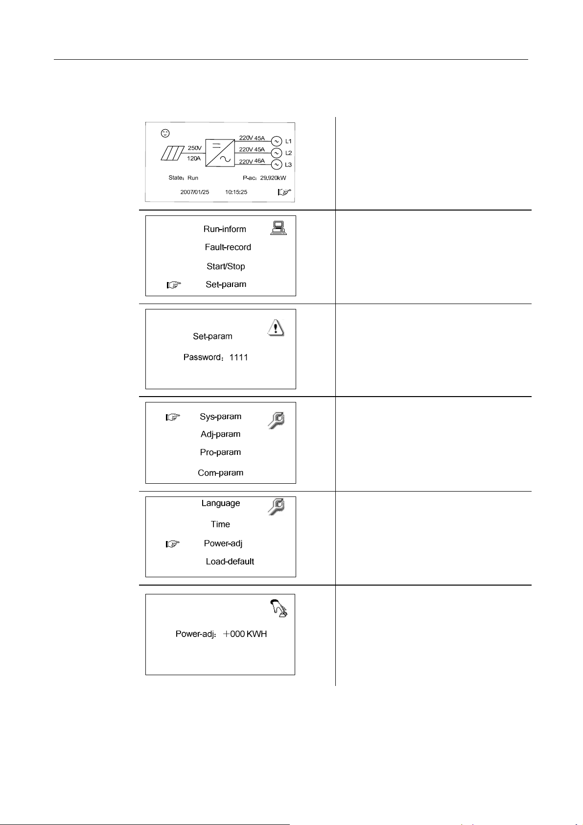
Monitoring and Data Interface 4
4.3.12 Output Energy Value Adjustment
Output Energy Value Adjustment
Output Energy Value AdjustmentOutput Energy Value Adjustment
1. In the default menu.
2. Press “ENTER” or “►” to enter the
general control menu
3. Navigate the hand-pointer to the
“Set-param” and press “ENTER”
button.
4. Press “ENTER” button to confirm
the password input.
Note that the default password is
1111.
5. Navigate the hand-pointer to the
“Sys-param” and press “ENTER”
button.
6. Move the hand-pointer to the
“Power-adj” and press “ENTER”
button.
7. Use “◄”and “►”to choose digits,
employ “▲”and “▼” to increase or
decrease number.
8. Input real value you read from your
electric meter and press “Enter” to
confirm them.
29
Page 38

SG30K3 User Manual
Note that the positive symbol “+” can also be changed to negative symbol “-”.
This generated power adjustment screen is useful in case the total-power displayed
by LCD (E-total) has difference with reading value from the external power measuring
device (like an electrical meter).
The adjustable range is from -999-+999 kWh.
(Power-adj value)= (Real measured value)-(E-total reading value)
30
Page 39
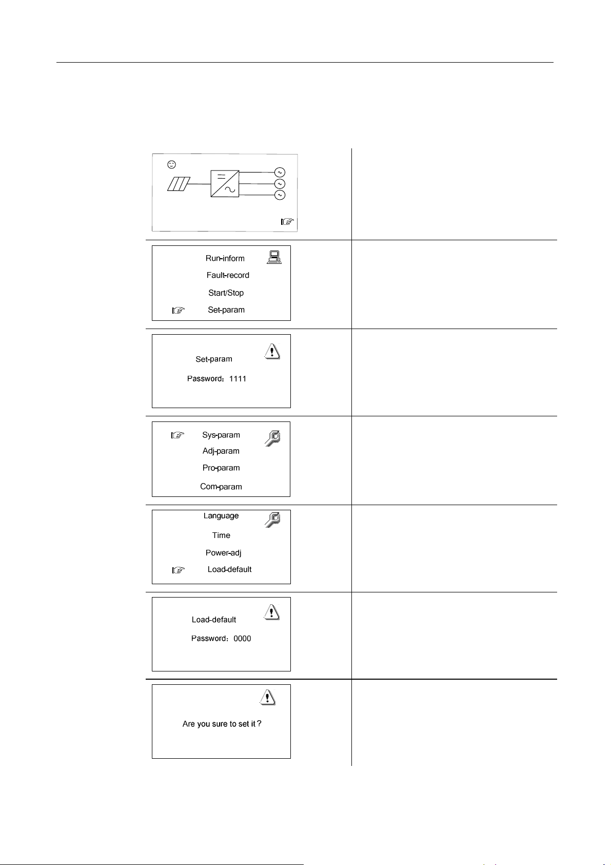
Monitoring and Data Interface 4
4.3.13 Load Default Setting
Load Default Setting
Load Default SettingLoad Default Setting
After load default, all the logged data and fault will be cleared.
2
5
0
V
1
2
0
A
S
t
a
t
e
:
R
u
n
2
0
0
7
/
0
1
/
2
5
1
0
:
1
2
2
0
V
4
5
A
L
2
2
0
V
4
4
2
2
0
V
P
-
a
c
:
5
:
2
5
1
5
A
L
2
6
A
L
3
2
9
.
9
2
W
0
k
2. Press “ENTER” or “►” to enter the
general control menu
3. Navigate the hand-pointer to the
“Set-param” and press “ENTER”
button.
1. In the default menu.
4. Press “ENTER” button to confirm
the password input.
Note that the default password is
1111.
5. Navigate the hand-pointer to the
“Sys-param” and press “ENTER”
button.
6. Move the hand-pointer to the
“Load-default” and press “ENTER”
button.
7. Input correct password 1111 and
press “Enter”.
8. Press “Enter” to re-confirm your
load default command.
31
Page 40
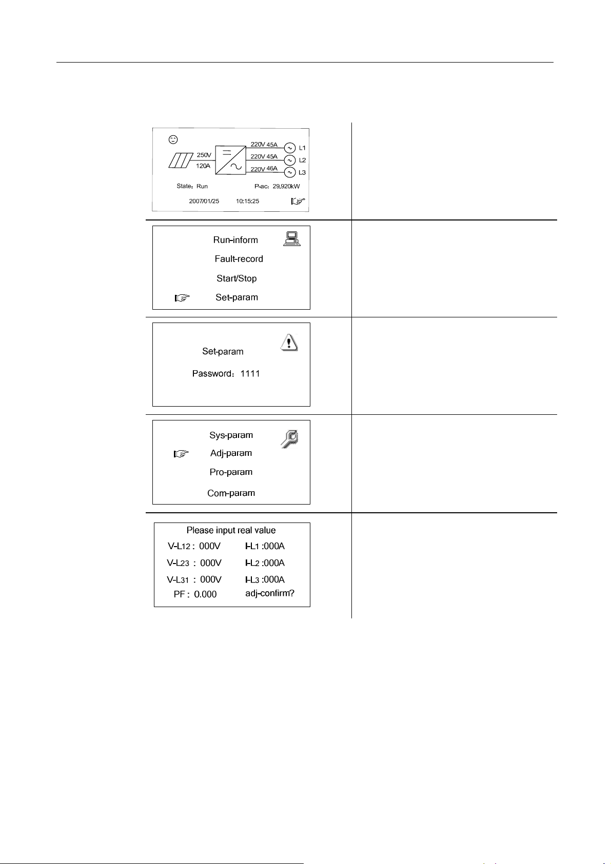
SG30K3 User Manual
4.3.14 Displayed Real
Displayed Real----time Parameters Adjustment
Displayed RealDisplayed Real
time Parameters Adjustment
time Parameters Adjustmenttime Parameters Adjustment
1. In the default menu.
2. Press “ENTER” or “►” to enter the
general control menu
3. Navigate the hand-pointer to the
“Set-param” and press “ENTER”
button.
4. Press “ENTER” button to confirm
the password input.
Note that the default password is
1111.
5. Navigate the hand-pointer to the
“Adj-param” and press “ENTER”
button.
6. Use “◄”and “►”to choose digits,
employ “▲”and “▼” to increase or
decrease number.
7. Input real value you read from your
electric meter and press “Enter” to
The “Adj-param” menu is designed to adjust the difference between the LCD
displayed value and the users measured real value and perform the adjustment of
displayed real data.
“V-L12”,”V-L23”,”V-L31” are the user measured three phase line to line
voltage, ”I-L1”,”I-L2”,”I-L3” are the user measured three phase current. PF is
measured power factor.
confirm them.
32
Page 41
Monitoring and Data Interface 4
4.3.15 Communication Parameters Setting
Communication Parameters Setting
Communication Parameters SettingCommunication Parameters Setting
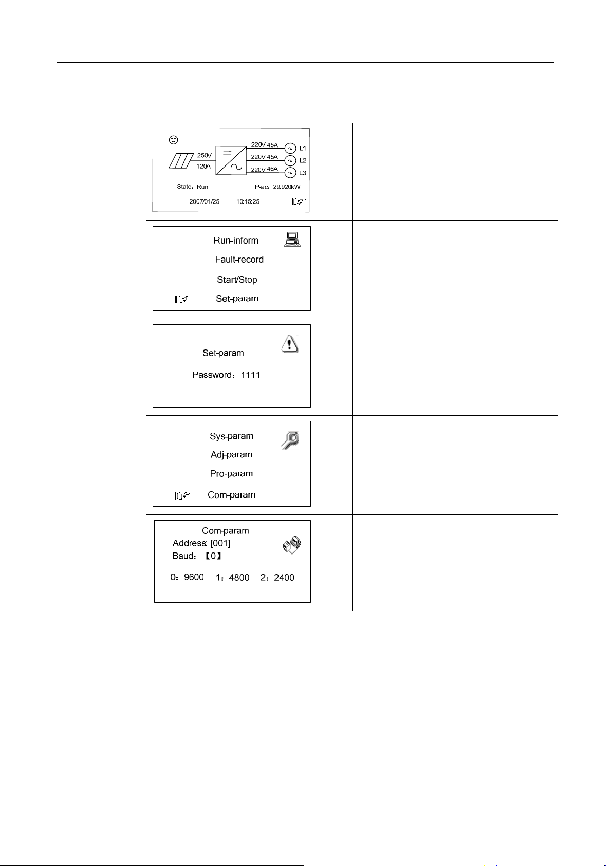
1. In the default menu.
2. Press “ENTER” or “►” to enter the
general control menu
3. Navigate the hand-pointer to the
“Set-param” and press “ENTER”
button.
4. Press “ENTER” button to confirm
the password input.
Note that the default password is
1111.
5. Navigate the hand-pointer to the
“Com-param” and press “ENTER”
button.
6. Use “◄”and “►”to choose digits,
employ “▲”and “▼” to increase or
decrease number.
7. Input the address and baud rate you
“Com-param” menu contains some basic communication parameters of the inverter
when connected to external monitoring device through RS485 serial communication
protocol. The inverter communication address can be in the first line. The range of the
address is 1-255.The serial communication baud rate can be adjusted through
entering 0, 1 and 2 in the second line.0 represents 9600 Baud, 1 means 4800 Baud
and 2 for 2400 Baud.
want.
33
Page 42

SG30K3 User Manual
The address parameter is very important when your solar generation application
contains many inverters and each inverter should have a unique address for serial
communication.
34
Page 43

5 Installation
About This Chapter
Installation
InstallationInstallation
This chapter gives installation instructions for SG30K3.
35
Page 44
SG30K3 User Manual
5.1
Safety Mounting Instructions
Safety Mounting Instructions
Safety Mounting InstructionsSafety Mounting Instructions
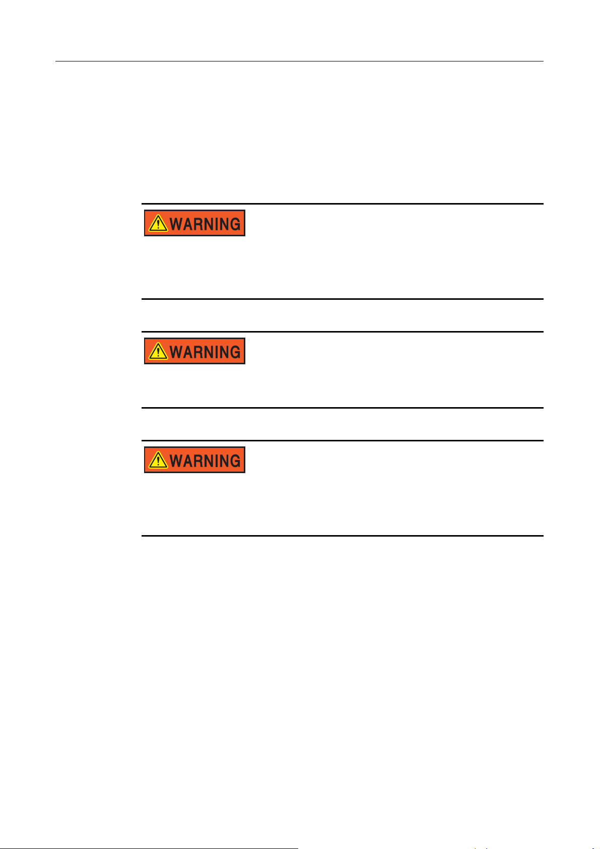
As with any electrical system, touching live components can be hazardous to life and
limb. This device contains DC voltage of up to 450V and the grid voltage up to 450V.
Only a qualified person can work on SG30K3.
This work is only permissible if the AC and DC power supplies are safely
disconnected from the SG30K3.
Before any maintenance, always wait for approx.10 minutes so that the
capacitors in the SG30K3 can discharge. Only then may the cover be opened.
Hot surface!
SG30K3 contains some parts, such as heatsinks of power semiconductors,
remain hot for a while after disconnection from electrical supply.
36
Page 45
5.2
Checking for Shipping Damage
Checking for Shipping Damage
Checking for Shipping DamageChecking for Shipping Damage
The SG30K3 inverters are thoroughly checked and tested rigorously before they are
shipped. Even though they are delivered in a rugged, heavy cardboard box, the
inverters can be damaged in shipping which typically is the shipping company’s fault.
So you should check the inverter before installation.
Please inspect the inverter thoroughly after it is delivered. If any damage is seen
please immediately notify the shipping company. If there is any question about
potential shipping damage, contact Sungrow Power Supply. A photo of the damage
may be helpful.
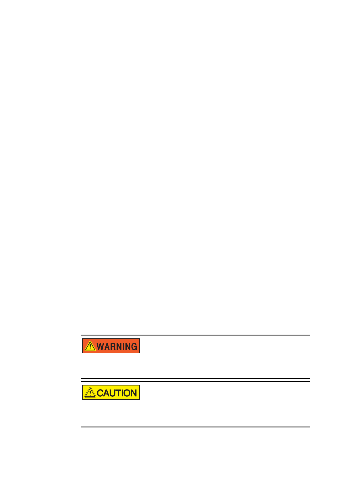
Do not accept unit if visibly damaged or note visible damage when signing shipping
company receipt. Please report the damage immediately to the shipping company. Do
not remove the unit from packaging.
Installation 5
5.3 Basic Installation Requirements
Basic Installation Requirements
Basic Installation RequirementsBasic Installation Requirements
The IP level of SG30K3 is IP20, so it can only be installed indoors. A list of these
requirements is shown below:
It is advised not to install the inverter in living quarters, since the inverter may
produce some operating noise.
Avoid installing the inverter in a location subject to vibrations.
The LED and display should always be legible for users.
Maintain a minimum of 100 mm clearance in back, 1000mm in front and 600mm
on top of the SG30K3 for proper ventilation and installation operation.
The ambient temperature should be within -25°C and +55°C.
The inverter should be mounted in a well-ventilated area.
Avoid mounting the inverter in a dusty area
Never install the SG30K3 in areas that contain explosive atmospheres (battery
rooms, fuel storage rooms etc).
Some parts of the SG30K3 can reach temperature of over 80°C.
Keep a suitable distance from flammable materials!
37
Page 46
SG30K3 User Manual
5.4
Mechanical Mounting
Mechanical Mounting
Mechanical MountingMechanical Mounting
5.4.1 Device Dimensions and Weight
Device Dimensions and Weight
Device Dimensions and WeightDevice Dimensions and Weight
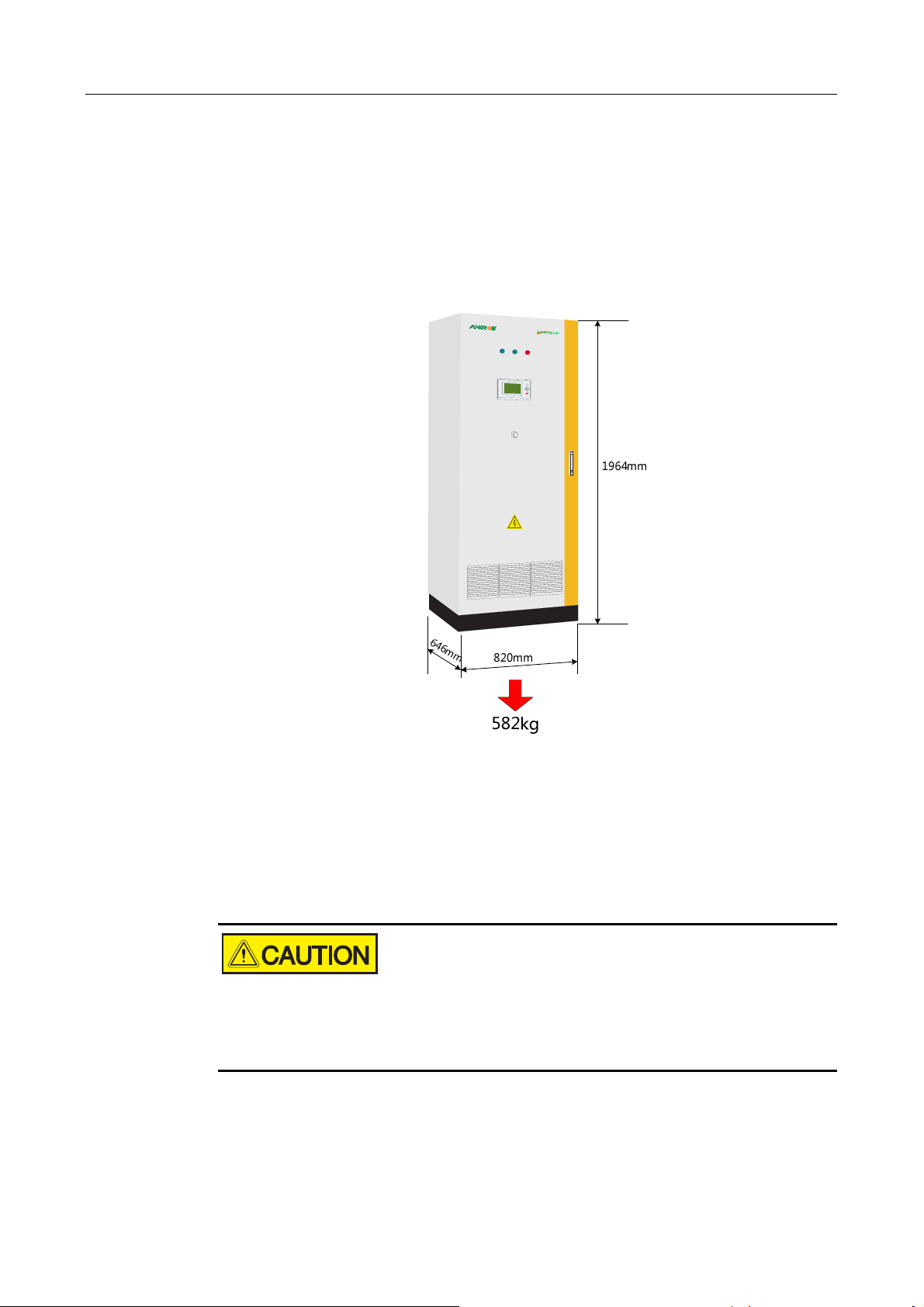
The external dimensions and weight of the SG30K3 is in Fig 5-1.
5.4.2 Moving SG30K3
Moving SG30K3
Moving SG30K3Moving SG30K3
Moving the Wrapped Unit
Crane, fork-lift or pallet truck can be used to move the wrapped unit.
Always remember the weigh of unit.
Pay attention to “CENTER OF BALANCE” and “HEAVE HERE” marking on the
wooden crate.
Unpacking the Unit
To unpack the SG30K3 from the Shipping crate:
Fig 5-1 Dimensions of SG30K3
38
Page 47
1. Remove the crate’s wood side and top panels.
2. Remove the barrier bag material from the inverter.
3. Remove the inverter’s anchor hardware that bolts the inverter to the pallet.
Moving SG30K3 after Unpacking
There are 3 ways to move unpacked SG30K3 to the final position.
Using fork-lift or pallet truck to move the SG30K3:
− Take down the front and rear cover of pedestal.
− Place the two forks below the unit with the gravity center in between,
− Lift the SG30K3 from beneath the enclosure.
Move the SG30K3 on the steel slideway.
If you need to move the SG30K3 using crane, contact SUNGROW to claim lifting
rings for free.
Installation 5
Always keep the SG30K3 upright!
Avoid sudden force!
5.4.3 Fastening the
Fastening the UUUUnit to the
Fastening the Fastening the
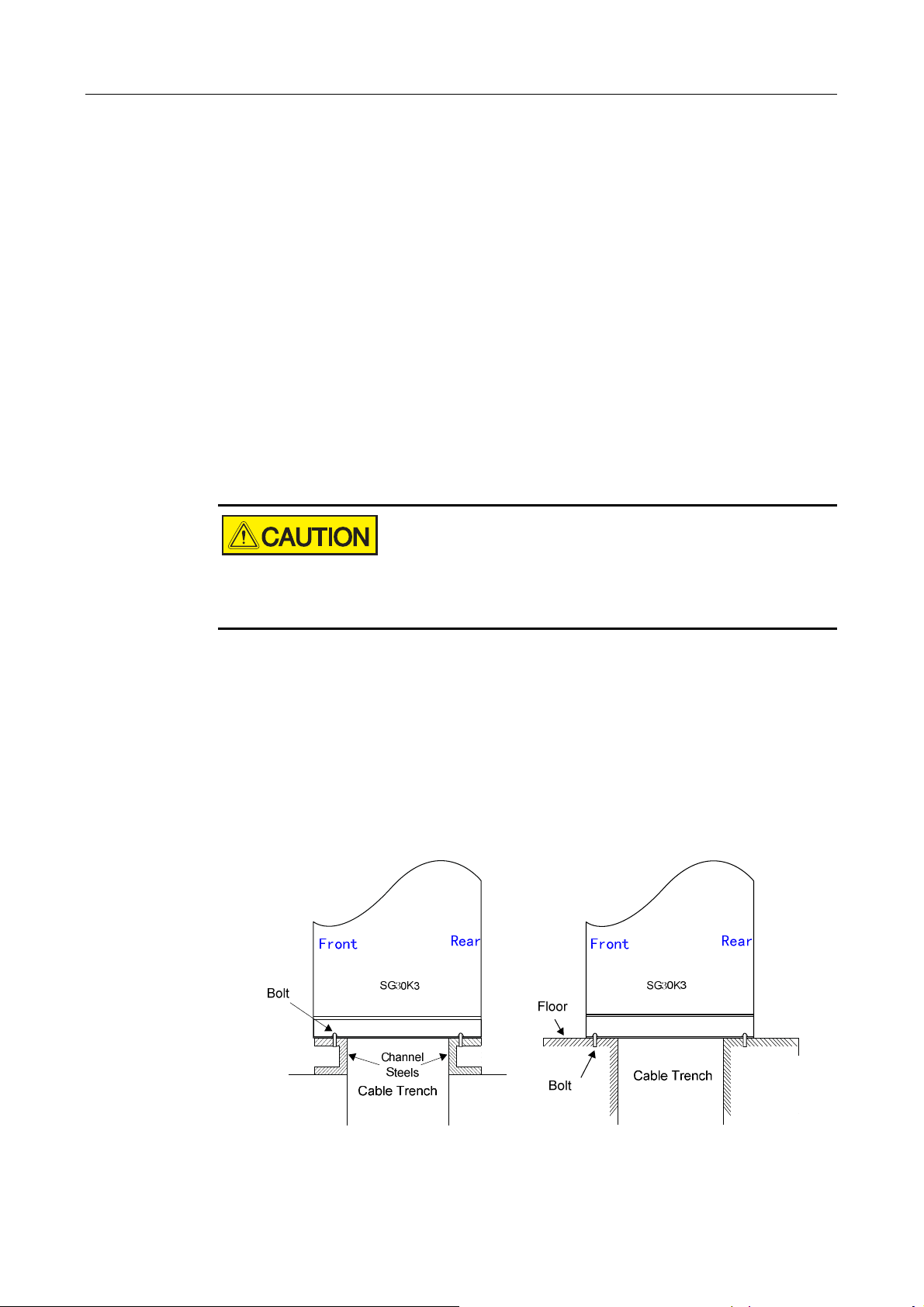
SG30K3 must be fastened to the floor as follows:
1. Remove the front and rear base covers.
2. Fasten the cabinet to the channel steels or roof using M12 bolts and nuts.
3. Reassemble the front and rear cover (or after the electrical connection finished).
nit to the FFFFloor
nit to the nit to the
loor
loorloor
Fig 5-2 Fasten SG30K3
39
Page 48
SG30K3 User Manual
5.5
Electrical Connection
Electrical Connection
Electrical ConnectionElectrical Connection
5.5.1 Electrical Connection Requirements
Electrical Connection Requirements
Electrical Connection RequirementsElectrical Connection Requirements
Grid
The SG30K3 is designed for 400V grid (three phase).The voltage should be
within 310V to 450V and the frequency should be the frequency should be
47~51.5Hz/57~61.5Hz.
Table 5-1 Grid request
Parameter Specification
Grid Voltage Range 310V~450V
Grid Frequency Range 47Hz~51.5Hz/57Hz~61.5Hz
PV array limit
Table 5-2 PV array limit
Parameter Specification
Max. PV Power 33kWp
Max. PV Voltage 450V
Ground
The inverter must be grounded in compliance with local safety codes using
appropriately sized protective conductors.
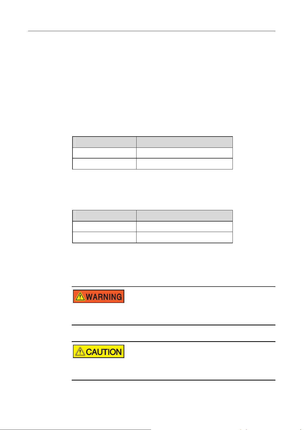
Make sure that the DC input voltage never exceeds 450V.Higher input voltages
will damage the SG30K3.
All electrical installations must comply with all local and national electrical
codes.
40
Page 49
Installation 5
5.5.2 Wires
Wires CCCConnection
Wires Wires
onnection
onnection onnection
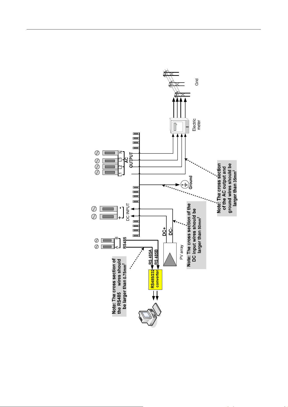
The complete wiring for a SG30K3 is shown schematically in the Fig 5-3.
Fig 5-3 Simplified Electrical Connection Diagram
41
Page 50
SG30K3 User Manual
Connect the AC Terminals
SG30K3 is designed to be installed in Three-phase Three-wire or Three-phase
Four-wire AC Voltage system.
Isolate the grid (switch off the circuit breaker), and secure it against accidental
reactivation.
Connect the wires of the AC cable as follows(through circuit breaker):
− Grid L1 wire to the terminal marked “L1”.
− Grid L2 wire to the terminal marked “L2”.
− Grid L3 wire to the terminal marked “L3”.
− Grid Neutral wire to the terminal marked “N” or leave the terminal vacant
Connect the DC Terminals
Grounding
Isolate the PV array and secure it against accidental reactivation.
Use a multimeter to check DC open circuit voltage less than 450V and confirm
the positive and negative poles.
Connect the wires of the DC cable as follows(through circuit breaker):
− PV array DC + wire to the inverter DC+.
− PV array DC - wire to the inverter DC -.
Please make sure that all wires are firmly connected.
Grounding is required for each SG30K3.
Connect the factory ground to the ground terminal with leaking current detector, to
realize the leaking current detect function.
If PV array DC input grounding is required, please connect DC+ or DC- terminal to
ground copper bar by 16mm2 ground wire as Fig 5-4.
42
Page 51
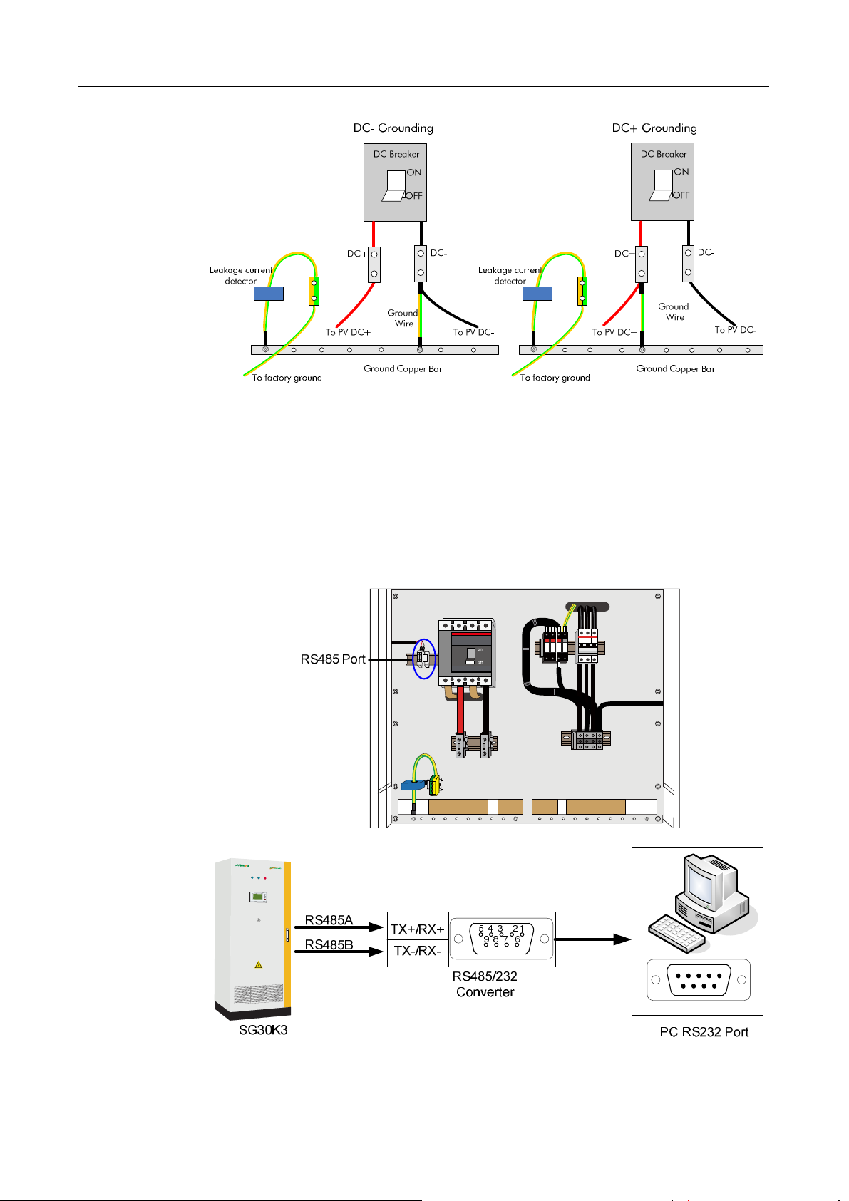
Fig 5-4 DC input connection diagram
5.6 Communication Installation
Communication Installation
Communication InstallationCommunication Installation
Installation 5
Fig 5-5 shows the communication installation of the SG30K3 with the PC by RS485
serial communication port, the wires and converter are optional for additional
purchase.
Fig 5-5 Communication Connection through Optional Converters
43
Page 52
SG30K3 User Manual
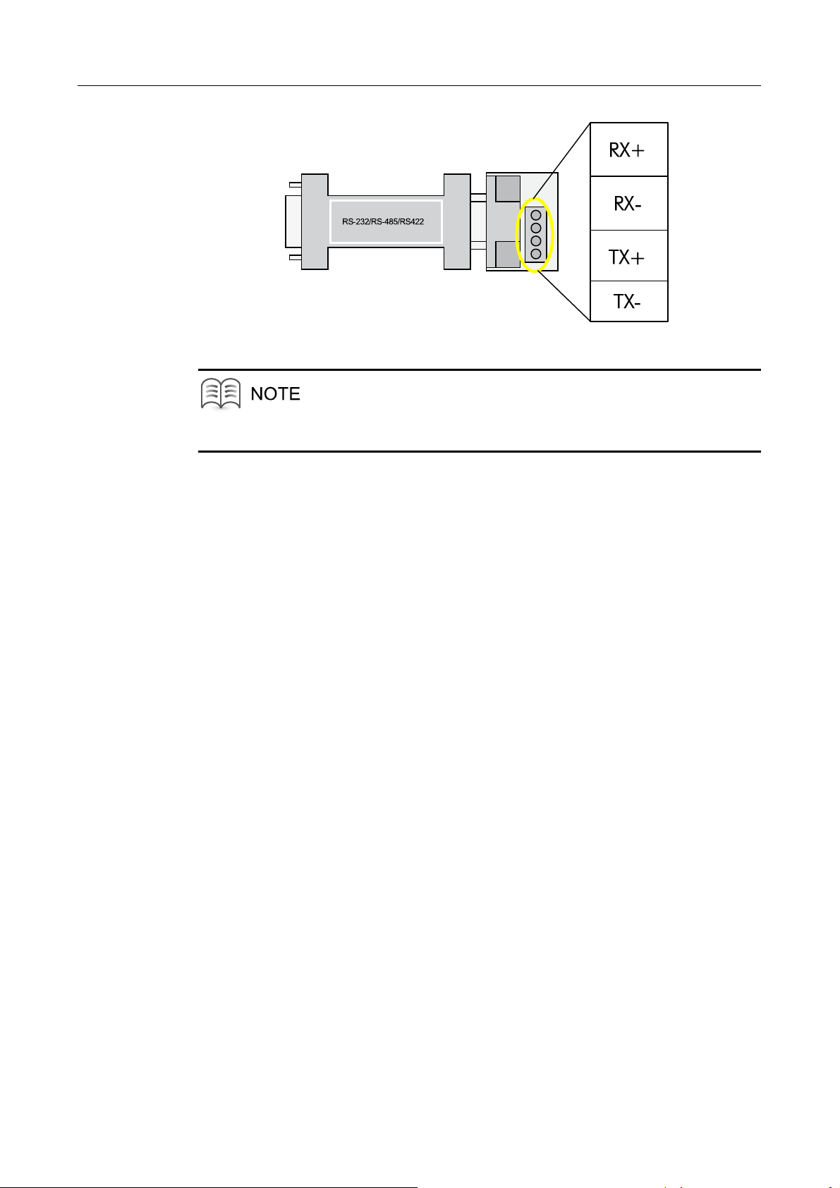
RS485/RS232 converter is optional for additional purchase.
If there are two or more inverters to be monitored, install communication system in
series.
Fig 5-6 RS485/RS232 converter
44
Page 53

6 Installation
About This Chapter
Installation CCCChecklist
Installation Installation
This chapter describes the items needed to verify whether your installation of the
SG30K3 is correct.
hecklist
hecklisthecklist
45
Page 54
SG30K3 User Manual
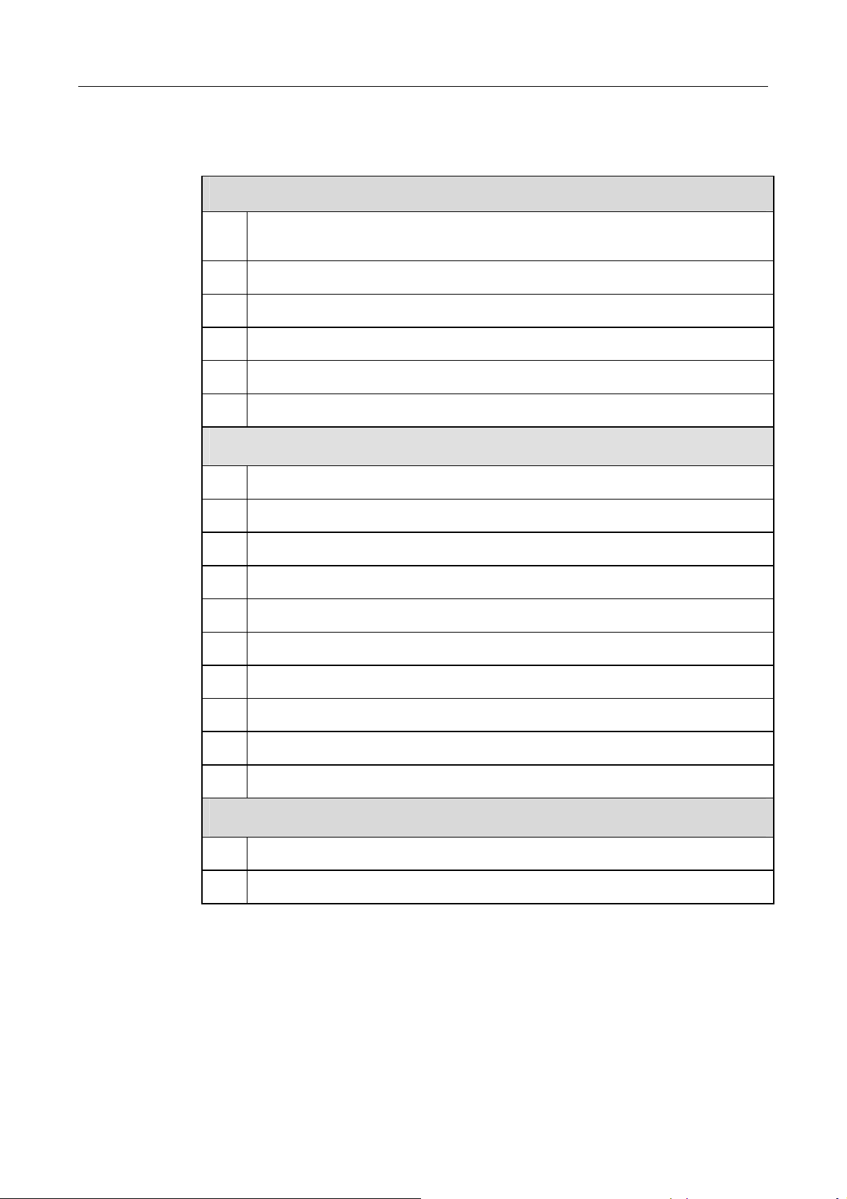
Check the mechanical and electrical installation of the inverter before commissioning.
Go through the checklist below with another person together.
Mechanical Installation
□
□
□
□
□
□
Check all the mechanical connections and make sure there is no damage, scratch or
abnormal parts
The inverter has been fixed properly to floor.
The clearance spaces around the inverter are proper.
The ambient operating conditions are within the allowed limits.
Cooling air circulates smoothly.
Protective enclosure seal is of integrity and reliability
Electrical Installation
□
□
□
□
□
The inverter is grounded properly.
The polarity of PV input connections are correct.
The grid voltage matches the nominal input voltage of the inverter.
The grid connection to the output terminals is OK.
The communication cable connections are correct.
□
□
□
□
□
Other
□
□
The communication cables are routed away from power cables.
Marks on the cables are correct, clear and distinguishable
Insulation shields are integrated and firm.
Warning labels are clear and distinguishable.
Make sure all the bolts that fix the cables are tightened and secured.
There are no tools, foreign objects or dust from drilling inside the inverter.
No condensing or icing in the cabinet.
46
Page 55

7 Commissioning
About This Chapter
Commissioning
CommissioningCommissioning
This chapter describes how to start the SG30K3 for the first time, including
requirements of commissioning, Inspection before start-up, start-up procedures and
completing the commissioning.
47
Page 56
SG30K3 User Manual
7.1
Requirements of Commissioning
Requirements of Commissioning
Requirements of CommissioningRequirements of Commissioning
Before starting the device for the first time, all work performed on the device
should be checked thoroughly.
Check the voltages in both AC and DC sides meet the requirements of SG30K3.
7.2 Inspection
Inspection before Start
InspectionInspection
before Start----up
before Startbefore Start
up
upup
7.2.1 PV Array Check
7.2.2 SG30K3
7.2.3 Ground
PV Array Check
PV Array CheckPV Array Check
Before start-up check the PV array:
1. Check open-circuit voltage of each PV string matches the nominal input voltage.
2. Record the U-I curve if possible.
3. Record the environmental parameters(temperature, radiation intensity)
4. Measure and record the resistance of cables if possible.
SG30K3 Check
SG30K3SG30K3
Ground Con
Ground Ground
Check
Check Check
Before start-up check the SG30K3:
1. Ensure that the mechanical and electrical installation of the inverter has been
checked according to 6 Installation Checklist.
2. Ensure that the DC and AC breaks are in “OFF” position.
3. Ensure that the Emergency Stop Button is released and functional.
Connection
nection Check
ConCon
nectionnection
Check
Check Check
Make sure the ground cable goes through the hole of the ground fault detection
device and is connected to the factory ground securely.
48
Page 57
Commissioning 7
7.2.4 Serial Communication Check (Optional)
7.2.5 Voltages
Serial Communication Check (Optional)
Serial Communication Check (Optional) Serial Communication Check (Optional)
For external communication monitoring, the data cables must be connected. Make
sure that the RS485 A and B cables are connected correctly and tightened to the
RS485/232 converter.
Make sure the RS485/232 converter terminal is correctly connected to the PC serial
port.
Voltages Check
VoltagesVoltages
Check
Check Check
AC Grid Voltage Check
It must be verified that the inverter is connected to the correct grid type and that a
right-hand rotary field exists on L1, L2, L3 and Neutral. The value of the AC line to line
voltage should be about 400 V.
DC Voltage Check
The DC connections are from the DC combiner boxes to the inverter.
The voltage on the individual DC cables should be almost the same value and must
never exceed the allowable maximum DC voltage.
Besides the voltage values, the polarity of the DC inputs must also be verified. All DC
connections should be checked to ensure that they are mechanically tight.
The DC cables to be connected must be rates for minimum of 450V.
7.3 Start the Inverter
Start the Inverter
Start the InverterStart the Inverter
If all tests and measurements have been performed, and all measured values lie
within the acceptable range, then the device can be switched on for the first time.
Before start up the SG30K3, ensure that nobody is working on the inverter.
To start the SG30K3:
1. Verify 400 VAC voltage of the grid line to line voltage.
2. Turn the AC break to the “ON” position.
49
Page 58
SG30K3 User Manual
3. Turn the DC break to the “ON” position.
4. It will take about 10 seconds for the auto-initialization of the power conversion
circuit and the LCD panel. The “POWER” LED indicators will burn.
5. If the DC voltage is below the DC voltage start point (Vpv<240V), then the “state”
of the LCD interface will always show “Start-up”;
6. If the DC voltage exceeds the DC voltage start point (Vpv >240V) for 3 minutes,
the SG30K3 will automatically change to “Run” state, the “OPERATION” LED will
light, with the state of the LCD menu will change to “Run”.
7.4 Complete the Commissioning
Complete the Commissioning
Complete the Commissioning Complete the Commissioning
If all the start procedures have been performed, check the operating condition of the
SG30K3.
1. Check whether the following items normal: noise, heat generation, no smoke or
unusual odor.
2. Measure the grid-connected voltage, current and THD.
3. Check the earthing of cabinet.
4. Check the LCD display and external communication.
So far, the commissioning of the SG30K3 is completed.
SG30K3 don’t need manual control in daily operation.
Keep the door closed and locked.
Key to the door must be stored by appointed personnel.
50
Page 59

8 Operation
About This Chapter
Operation
OperationOperation
This chapter describes the operation of the SG30K3, exclusion of liability and the way
to contact us.
51
Page 60

SG30K3 User Manual
SG30K3 inverter is a fully automated grid-connected solar inverter. Most of the
functions and modes transition are performed automatically.
8.1 Start the Inverter
Start the Inverter
Start the InverterStart the Inverter
To turn on the inverter, please follow the steps below.
1. Switch on the DC side circuit breaker
2. Switch on the AC side breaker
3. The inverter will to check whether that voltage, impedance and frequency
parameters are within operating range.
4. If the parameters check is correct, then the LCD will display the normal working
screen.
5. Then the inverter will export to the grid and the green Power LED will
continuously lit (provided there is enough PV power).
8.2 Stop
Stop the Inverter
StopStop
the Inverter
the Inverter the Inverter
1. If users want to shut down the inverter, please refer to stop command in the LCD
menu.
2. If users want to shut down the inverter immediately in an emergency, please
press down the emergency stop button.
52
Page 61

9 Maintenance
About This Chapter
Maintenance
MaintenanceMaintenance
This chapter describes the maintenance instructions needed to keep SG30K3 at its
optimum performance.
53
Page 62
SG30K3 User Manual
Due to the effect of the ambient temperature, humidity, dust and vibration, the inner
components of the inverter will be aged and worn out. It is necessary to implement
routine and periodic maintenance to the inverter. This section introduces maintenance
items and intervals.
Only qualified personnel can service the inverter!
Before any maintenance work, please do as follows:
Shut off the inverter or disconnect the DC/AC connections
Cut off auxiliary power supply
Wait at least 15 minutes until the inner capacitors to discharge
Open the door and measure the voltage of the terminals and intermediate circuit
terminals. Make sure that there is no lethal voltage.
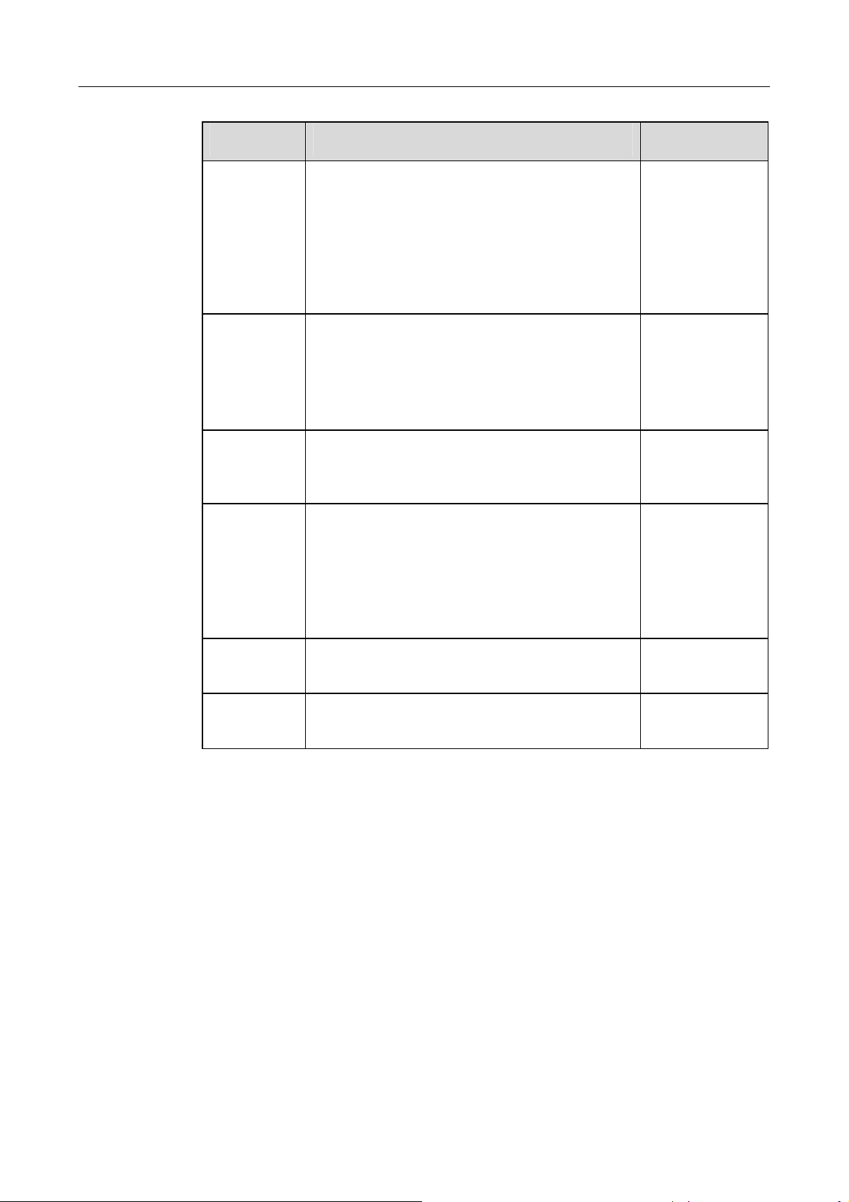
Implement the maintenance work periodically and record the maintenance work in the
maintenance report, specified in the following table.
Items Methods Period
Save data Save the running data, parameters and log to a disk or a
file.
Update software.
General state
of system
Visual check any damage or deformation of the inverter.
Check any abnormal noise during the running of the
inverter.
Check each parameter of inverter operation.
Check the important component.
Check if the temperature of the housing is normal.
Monitor the system using the thermal imager.
Check the humidity and dust of the environment.
Meanwhile check whether the filter function of the air
inlet is ok.
Check the warning labels, and replace if necessary.
Once a month
Twice every year
System clean Check whether the circuit board and the component are
clean.
Check the temperature and dust of the inverter.
Dismantle the fan and clean the module if necessary.
54
Six months to a
year(it depends on
the dust contents in
air.)
Page 63
Maintenance 9
Items Methods Period
Power circuits
connection
Terminals and
cables
Fan Check whether there is crack on fan blades.
Circuit breaker Routine check the corrosion state of metal components
Check whether power cable connections are loose.
Re-tighten them with the torque specified in the manual.
Check whether there are damages in the power cables
and control cables, especially the surface in contact with
the metal.
Check whether the wrap belts of the connection
terminals is strip-off.
Check whether the screws of control terminals are
loose. Re-fasten by screwdriver, wherever necessary.
Check whether the terminals of the main circuit are poor
contact and whether the screws are burnt.
Visual check all connections and cable distributions.
Check whether there is any abnormal noise during the
fan rotating.
(once every half a year).
Check contactors every year (auxiliary switches and
micro switches included).
Check the running parameters (voltage and insulation
especially).
First 6 months after
commissioning and
then once or twice
a year.
Once every year
Once a year
Once or twice a
year
Safety function Check the LCD stop and emergency stop circuit.
Analog shutdown and check stop signal communication.
Software Software optimization.
Check the setting of every parameter.
Once or twice a
year
Once or twice a
year
55
Page 64

SG30K3 User Manual
56
Page 65

10 Troubleshooting
About This Chapter
This chapter gives the basic troubleshooting methods to the customer as a reference.
Troubleshooting
TroubleshootingTroubleshooting
57
Page 66
SG30K3 User Manual
10.1
LED Indicated Fault Troubleshooting
LED Indicated Fault Troubleshooting
LED Indicated Fault TroubleshootingLED Indicated Fault Troubleshooting
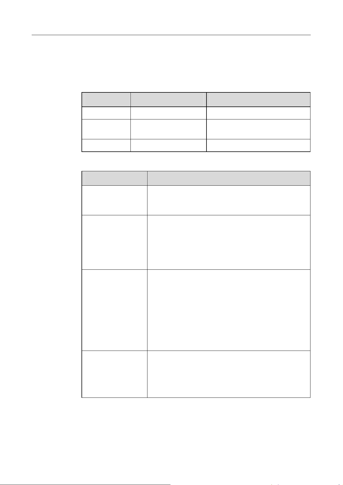
Table 10-1 LED states during normal working
LED Name State Explanation
POWER light The power supply of the inner circuit is OK
OPERATION light The inverter is in correct grid connection
FAULT shut No fault occurs
Table 10-2 LED fault and simple troubleshooting
LED state Explanation
No LED flashes and LCD
screen no display
POWER shut Power supply of the inverter is not working.
Disconnect the AC and DC voltage and keep disconnected for 5 min.
Afterwards, reconnect the DC voltage and then the AC voltage.
If the device does still not run it needs to be exchanged or repaired.
First make sure that the grid is available and grid connection wires
are OK. Disconnect the AC and DC voltage and keep disconnected
for 5 min. Afterwards, reconnect the DC voltage and then the AC
voltage.
If the power LED never light after restart, please contact Sungrow.
working state
Operation shut The inverter is not in the grid connection state.
First check all the AC and DC wires are correctly connected.
Use multimeter to measure the DC input voltage and make sure the
DC input voltage exceeds the start threshold of the inverter
operation.
Make sure the grid is available and parameters are within the
inverter specification.
If all the conditions above are checked OK and this light still not light,
Please contact Sungrow.
FAULT light A fault has occurred and is not solved.
Please refer to the LCD screen fault message for the detailed fault
information and accordingly take troubleshooting. This LED will shut
when the fault disappears.
Please contact Sungrow if this LED keeps light all the time.
58
Page 67
Troubleshooting 10
10.2
LCD
LCD Displayed Fault Troubleshooting
LCDLCD
Displayed Fault Troubleshooting
Displayed Fault Troubleshooting Displayed Fault Troubleshooting
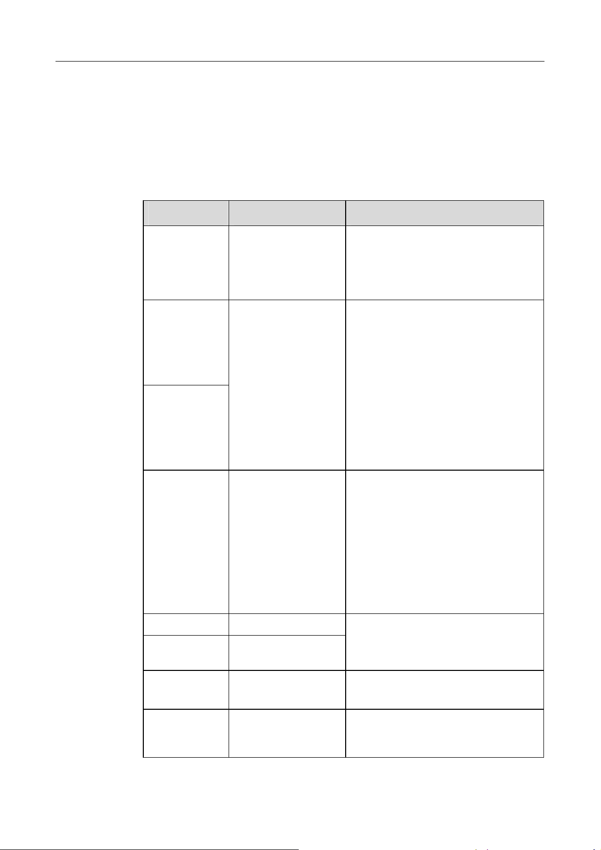
If a fault occurs, the SG30K3 will generate a message and display the message in the
“state:” position.
Table 10-3 Displayed Fault description and troubleshooting
Fault Name Description Troubleshooting
Vdc-high Over voltage on DC input
(>450V)
Vac-high
Vac-low
The grid voltage has
exceeded the permissible
range.
Disconnect the DC input of the SG30K3.
Otherwise the inverter could be severely
damaged! Check the configuration of your
system and measure the DC voltage before
reconnecting the inverter to the DC source.
Check the grid voltage and grid connections of
SG30K3. If the grid voltage lies outside the
range because of local conditions, ask the
electricity provider if the voltage can be
adjusted at the feed-in point or if they agree to
changes in the values of the monitored
operational limits.
If the grid voltage lies within an acceptable
range and “ Vac-high “ or “ Vac-low “ faults are
still being displayed, please contact the
Sungrow.
F-fault The grid frequency has
exceeded the permissible
range.
DSP-flt The DSP malfunction
Ipm-flt The IPM power module
malfunction
Cntr-flt AC side contactor fault This fault is un-recoverable.
Ttp-flt The transformer is
over-heat
Check the grid frequency and grid connections
of SG30K3. If the grid frequency lies outside
the acceptable range because of local
conditions, ask the electricity provider if the
voltage can be adjusted at the feed-in point or
if they agree to changes in the values of the
monitored operational limits.
If the grid frequency lies within an acceptable
range and “F-fault” is still being displayed,
please contact the Sungrow.
Stop the inverter and restart the inverter from
LCD, if this fault happens frequently, Please
contact Sungrow.
Please contact Sungrow if this fault happens.
Check the grid parameters .If all the
parameters are OK and this fault happens
frequently, Please contact Sungrow.
59
Page 68
SG30K3 User Manual
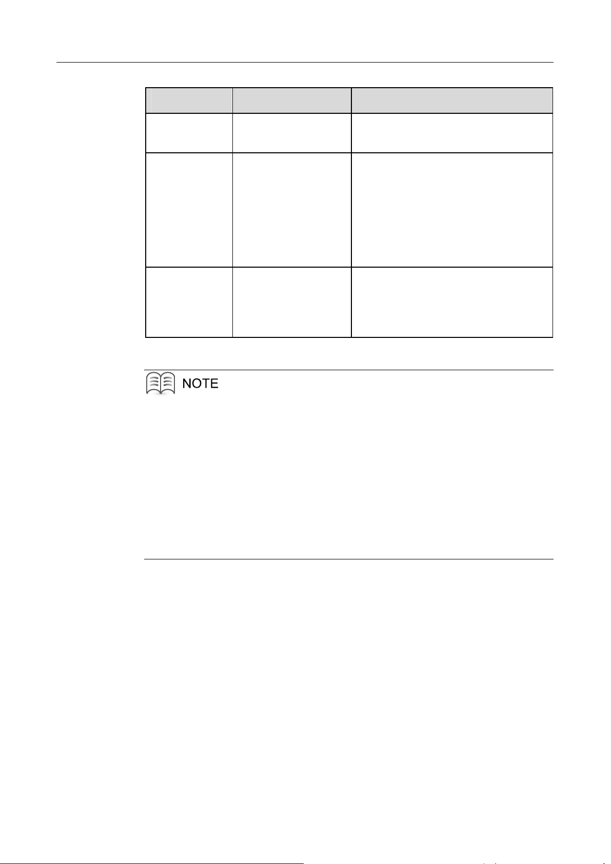
Fault Name Description Troubleshooting
Temp-flt The heatsink of the IPM is
overheat
Com-flt The communication
between the LCD screen
and the DSP
Gnd-flt Ground fault Check the ground wire.
Check whether the output power is too large
Check the cooling fan works OK
An internal communication fault occurs.
Wait for a moment to check whether this fault
will disappear.
Restart the inverter to see whether this fault
happens again.
Please contact Sungrow if this fault happens
frequently.
Check the ground fault detection device.
Normally the system will recover operation
after this fault is removed for 5 minutes.
If you have any problems in operating on the SG30K3, please contact us via service
hotline: +86 551 532 7834/532 7845 or e-mail: [email protected].
We need the following information to provide you the best assistance:
Type of the inverter
Serial number of the inverter
Fault name
Simple description of the fault phenomenon
60
Page 69

11 Appendix
About This Chapter
This chapter gives technical data of the SG30K3, exclusion of liability and the way to
contact us
Appendix
AppendixAppendix
61
Page 70
SG30K3 User Manual
11.1
11.1.1 Electrical Specifications
TTTTechnical Data
echnical Data
echnical Dataechnical Data
Electrical Specifications
Electrical SpecificationsElectrical Specifications
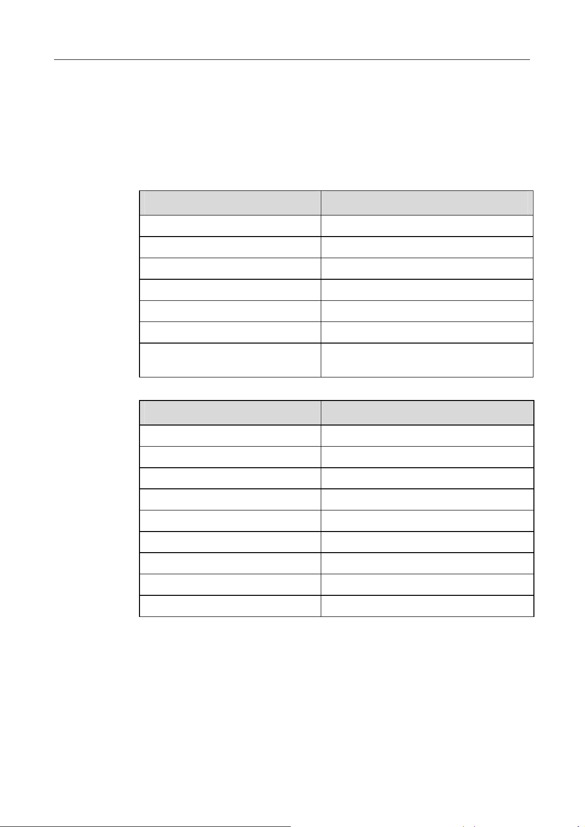
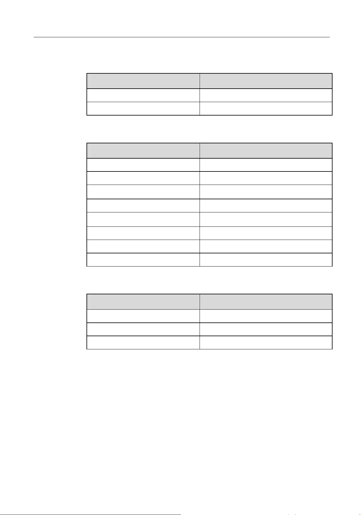
DC SIDE DATA
Parameter Specification
Maximum DC Voltage 450V
Start Voltage 240V
MPP Voltage Range 220~380Vdc
Min. DC Voltage 220V
Max. PV Power 33kWp
Max. Input Current 150A
Number of MPP Trackers/Strings Per MPP
Tracker
AC SIDE DATA
1/1
Parameter Specification
Rated Output Power 30kW
Max. AC Output Current 47A
Rated Grid Voltage 400Vac
AC Voltage Range 310~450Vac
Rated Grid Frequency 50Hz/60Hz
AC Frequency Range 47~51.5Hz/57~61.5Hz
Output Current THD <3% (at nominal power)
DC Current Injection <0.5% of rated inverter output current
Power Factor 0.95(lagging)~0.95(leading)
62
Page 71
Appendix 11
11.1.2 Mechanical Specifications
11.1.3 System
Mechanical Specifications
Mechanical SpecificationsMechanical Specifications
Parameter Specification
Dimensions(W x H x D) 820x1964 x646mm
Weight 582kg
System
SystemSystem
Parameter Specification
Peak Efficiency 94.5%(with transformer)
European Efficiency 93.5%(with transformer)
Protection Degree
Power Consumption at Night 0W
Operating Temperature
Cooling Method controlled forced-air cooling
IP20(indoor)
-25℃~+55℃
Relative Humidity 0~95%, non-condensing
Max. Working Altitude 2000m
11.1.4 Display and Communication
Display and Communication
Display and CommunicationDisplay and Communication
Parameter Specification
Display LCD
Communication(Standard) RS485
Communication(Optional) Ethernet/GPRS
63
Page 72

SG30K3 User Manual
11.2
Exclusion of Liability
Exclusion of Liability
Exclusion of Liability Exclusion of Liability
The content of these documents is periodically checked and revised, when necessary,
please call us or check our website www.sungrowpower.com for the latest information.
However discrepancies cannot be excluded. No guarantee is made for the
completeness of these documents. Please contact our company or distributors to get
the latest version.
Guarantee or liability claims for damages of any kind are excluded if they are caused
by one or more of the following:
Improper or inappropriate use or install of the product
Installing or operating the product in an unintended environment
Installing or operating the product when ignoring relevant safety regulations in
the deployment location
Ignoring safety warnings and instructions contained in all documents relevant to
the product
Installing or operating the product under incorrect safety or protection conditions
Altering the product or supplied software without authority
The product malfunctions due to operating attached or neighboring devices
beyond allowed limit values.
In case of unforeseen calamity or force majeure.
The use of supplied software produced by Sungrow Power Supply Co., Ltd.. is subject
to the following conditions:
Sungrow Power Supply Co., Ltd. rejects any liability for direct or indirect
damages arising from the use of the SunInfoTM software. This also applies to the
provision or non-provision of support activities.
Using the SunInfoTM software for commercial purposes is prohibited.
Decompiling, decoding or destroying the original program, including SunInfoTM
software and the embedded software, is prohibited.
64
Page 73
Appendix 11
11.3
About
About Us
AboutAbout
Us
Us Us
Sungrow power supply is a china-leading manufacturer of various power electronics
products for renewable energy generation systems. Our products include converters,
inverters, battery chargers, and other power supplies for distributable generation
system in both grid-connected and stand-alone applications. The power rating of
Sungrow products covers from several hundred watt to large mega-watt systems.
The pursuit of Sungrow is to help our customers acquire stable and clean power with
minimum cost, maximum reliability and enhanced safety.
Trademarks
Co., Ltd..
Contact Information
If you have any questions about this product, our hotline will be happy to assist you.
Please keep the following data when contacting Sungrow.
is the registered trademark of Sungrow Power Supply
Company: Sungrow Power Supply Co., Ltd.
Website: www.sungrowpower.com
Contact: Mr. Henry (Director of International Trade)
Address:
Zip: 230088
Telephone: +86 551 532 7834, +86 551 532 7845
Fax: +86 551 532 7856
No.2 Tianhu Rd., New & High Technology Industrial Development Zone,
Hefei, P.R.China.
65
Page 74
SG30K3 User Manual
66
 Loading...