

Page 1
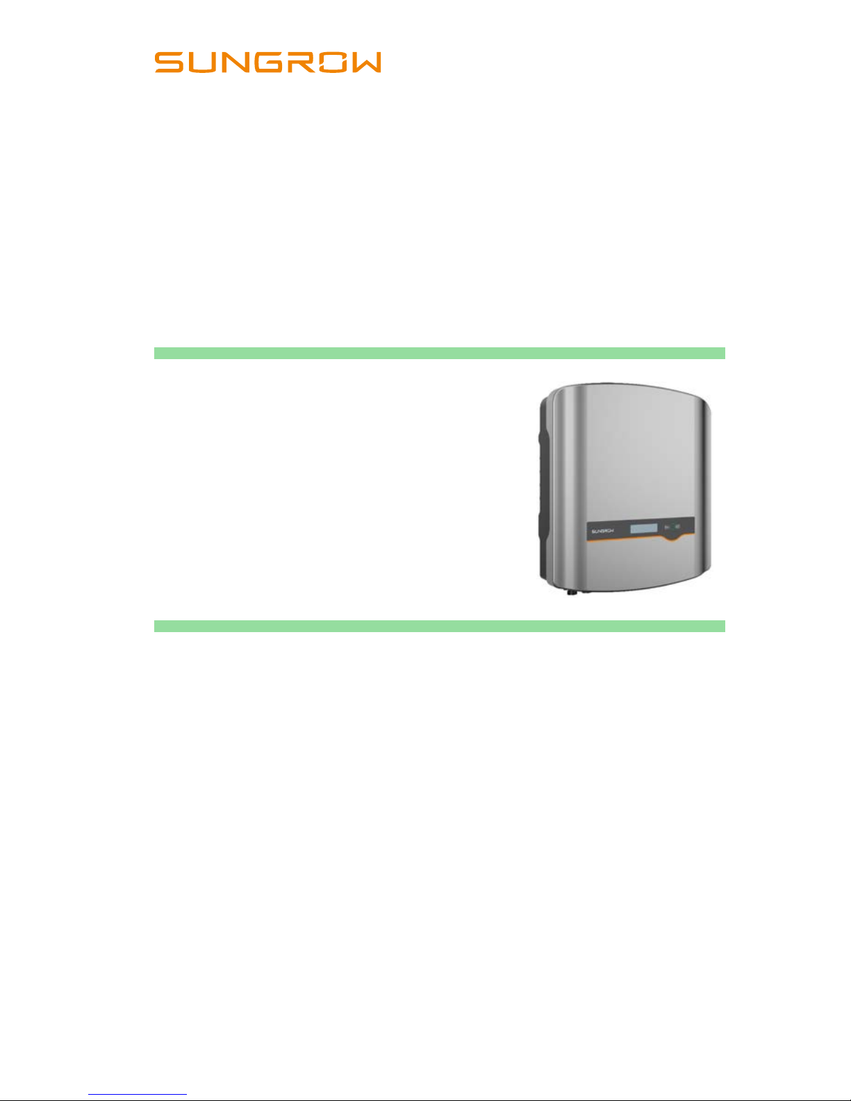
SG2_2.5_3_5_8K-UEN-Ver11 Version:1.1
User Manual
SG2K-S / SG2K5-S / SG3K-S /
SG3K-D / SG5K-D / SG8K-D
PV Grid-Connected
Inverter
Page 2

Page 3

I
About This Manual
The manual mainly describes t he product information, guidelines for installation,
operation and mai ntenance. The manual c annot include complete i nformation
about the phot ovoltaic (PV) system. You can get additional information ab out
other devices at www.sungrowpower.com or on the webpage of the respective
component manufacturer.
Applicability
This manual is applicable to the following inverter types:
SG2K-S
SG2K5-S
SG3K-S
SG3K-D
SG5K-D
SG8K-D
They will be ref erred to as “inverter” hereinafter unless otherwise specifi ed.
Target Group
This manual is intended for:
qualified personnel who are responsible for the installation and
commissioning of the inverter; and
inverter owners who will have the ability to interact with the inverter.
How to Use This Manual
Read the m anual and other r ela ted docum ents bef ore any wor k on the inverter
is carried out. Documents must be stored carefully and be available at all times.
All rights to the content of this manual are owned by Sungrow Power Supply
Co., Ltd. (herei nafter “SUNGROW”). No part of thi s doc ument can b e modified,
distributed, reproduc ed or publis hed in any form or by any means wit hout prior
written per m ission from SUNGROW.
Page 4
II
Contents may be periodical ly updated or revi sed due to product devel opment.
The informati on in this manual is subject to change without noti ce. The latest
manual can be ac quired at www.sungrowpower.com.
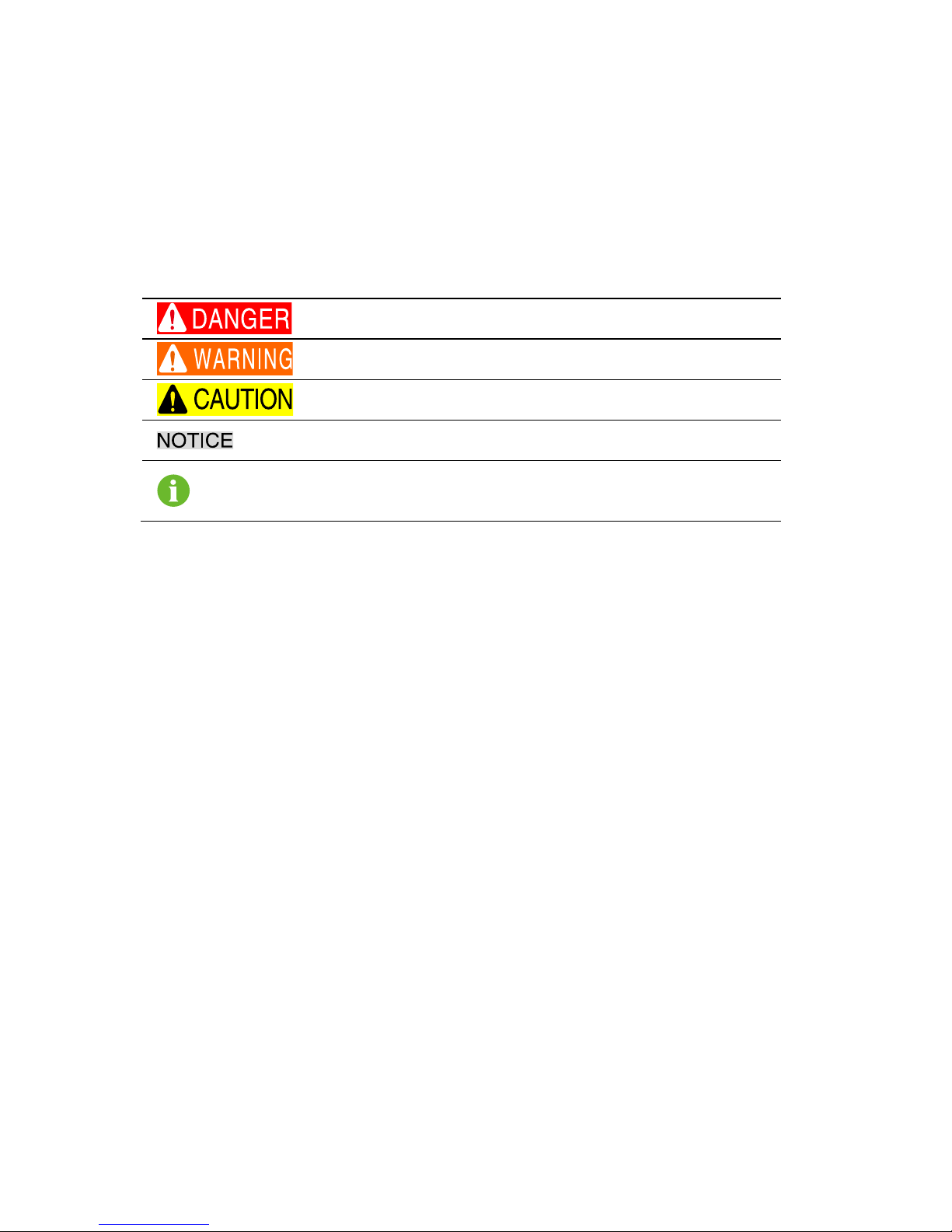
Symbols
Safety inst ructions will be highlighted with the following symbols.
Symbol
Explanation
Indicates a hazard with a high level of risk that, if not
avoided, will result in death or serious injury.
Indicates a hazard with a medium level of risk that, if not
avoided, could result in death or serious injury.
Indicates a hazard with a low level of risk that, if not
avoided, could result in minor or moderate injury.
Indicates a situation that, if not avoided, could result in
equipment or property damage.
Indicates additional information, emphasized contents or
tips that may be helpful, e.g. to help you solve problems or
save time.
Page 5

III
Contents
About This Manu al ..................................................................... I
1 Safety ....................................................................................1
1.1 General Safety .......................................................................... 1
1.2 Inverter ...................................................................................... 2
1.3 Skills of Qualified Personnel ...................................................... 3
2 Product Introduction ...........................................................4
2.1 Intended Use ............................................................................. 4
2.2 Inverter ...................................................................................... 5
2.3 Energy Meter (optional) ............................................................. 7
2.4 Function Description .................................................................. 8
2.4.1 Basic Function ........................................................................... 8
2.4.2 External Demand Response ...................................................... 9
2.4.3 Reactive Power Regulation ..................................................... 10
2.4.4 Power Quality Response ......................................................... 10
3 Unpa cki ng and S tor a ge .................................................... 11
3.1 Unpacking and Inspection ....................................................... 11
3.2 Identifying the Inverter ............................................................. 12
3.3 Delivery Contents .................................................................... 13
3.4 Storage of Inverter ................................................................... 14
4 Mechanic al Mou nti ng ........................................................15
4.1 Safety during Mounting ........................................................... 15
4.2 Location Requirements ........................................................... 15
4.3 Tools ........................................................................................ 17
4.4 Installing the Inverter ............................................................... 19
4.5 Installing the Energy Meter ...................................................... 21
5 Electrical Conne ct i on .......................................................22
5.1 Terminal Description ................................................................ 23
5.2 Grounding the Inverter ............................................................ 24
Page 6

IV
5.3 Grid Connection ....................................................................... 25
5.3.1 AC Side Requirements ............................................................ 25
5.3.2 Assembling the AC Connector ................................................. 26
5.3.3 Instal ling the AC Connect or ..................................................... 27
5.4 PV Connection ......................................................................... 28
5.4.1 PV Input Configuration ............................................................ 28
5.4.2 Assembling the PV Con nector ................................................. 31
5.4.3 Installing the PV Connector ..................................................... 32
5.5 RS485 Connection ................................................................... 33
5.6 Meter Connection..................................................................... 33
5.6.1 On the Meter Side ................................................................... 34
5.6.2 On the Inverter Side ................................................................ 36
5.7 DRM Connection to an External Device ................................... 37
6 Commissioning ................................................................. 39
6.1 Inspection before Commi ss ion ing ............................................ 39
6.2 Button Function ........................................................................ 39
6.3 Commissioning Procedure ....................................................... 40
7 LCD Operation ................................................................... 41
7.1 Button Function ........................................................................ 41
7.2 Main Screen ............................................................................. 41
7.3 Menu Structure ........................................................................ 43
7.4 Viewing Running Info ............................................................... 44
7.5 Advanced Settings ................................................................... 44
7.5.1 Inputt ing the Password ............................................................ 44
7.5.2 Setti ng P rotective Parameters ................................................. 44
7.5.3 Zero-e xport Setting ................................................................. 48
7.5.4 Adding the Existing Inverter ..................................................... 48
7.5.5 PF Setting ............................................................................... 48
7.5.6 Parameter Reset ..................................................................... 49
7.5.7 DRM Switch Setting ................................................................ 49
7.5.8 GND Detection ........................................................................ 49
7.5.9 Energy Adjustment .................................................................. 49
Page 7

V
7.5.10 Setti ng C om munication Par am eter ........................................ 49
7.5.11 Ethernet Configuration ........................................................... 50
7.6 Starting/Stopping the Inverter .................................................. 50
7.7 Viewing the Error Record ........................................................ 50
7.8 Setting the T ime ...................................................................... 50
7.9 Setting the Country .................................................................. 51
7.10 Viewing Device Info ................................................................. 53
8 T r oubl es ho otin g and Ma int ena nc e ..................................54
8.1 Troubleshooting ....................................................................... 54
8.1.1 LED Indicator .......................................................................... 54
8.1.2 Errors on the App or LCD Screen ............................................ 54
8.2 Routine Maintenance .............................................................. 60
9 System Decomm i ssi oning ...............................................62
9.1 Disconnecting the Inverter ....................................................... 62
9.2 Dismantling the Inverter .......................................................... 63
9.3 Disposing of the Inverter ......................................................... 63
10 Appendix ............................................................................64
10.1 Technical Data ......................................................................... 64
10.1.1 –S Seri es ............................................................................... 64
10.1.2 –D Series .............................................................................. 66
10.2 Quality Assurance ................................................................... 68
Page 8

Page 9
1
1 Safety
The inverter has been designed and tested strictly according to international
safety regul ations. Read all safety i nstructions careful ly prior to any work and
observe them at all times when working on or with the invert er.
Incorrect operation or work may cause:
injury or death to the operator or a third party; or
damage to the inver ter and other properties belonging to the operator or a
third party.
All detailed work -related safet y warnings and notes wi ll be specif ied at critical
points in this m anual.
1.1 General Safety
PV Panels
Please foll ow the safety instr uctions related to the PV strings.
Lethal voltage!
PV strings will produce elect rical power when exposed t o sunlight and
can cause a lethal voltage and an electric sho ck.
Only qualified personnel can perform the wiring of the PV panels.
Utility Grid
Please foll ow the regulations related to the utility grid.
All electrical connections must be in accordance with local and
national standards.
Only with the permission of the utility grid, the inverter can be
connected to the utility grid.
Page 10
1 Safety User Manual
2
1.2 Inverter
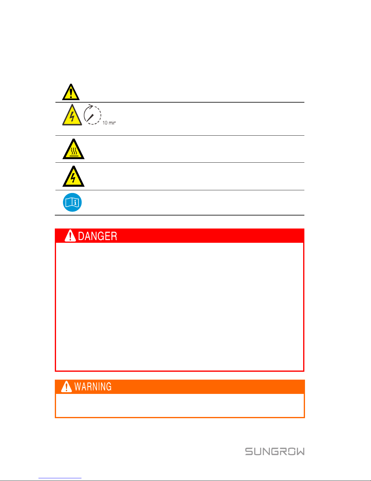
There is a warning label on the inverter body.
Disconnect the inverter from all the external power sources
before service!
Do not touch live parts until 10 minutes after disconnection
from the power sources.
There is a danger from a hot surface that may exceed
60°C.
Danger to life due to high voltages!
Only qualified personnel can open and service the inverter.
Check the user manual before service!
Danger to life from electric shocks d ue to live voltage
Do not open the enclosure at any time. Unauthorized opening will void
guarantee and warranty claims and in most cases terminate the operating
license.
When the enclosure lid is removed, live components can be touched
which can result in death or serious injury due to electric shock.
Danger to life from electric shock du e to damaged inverter
Only operate the inverter when it is technically faultless and in a safe
state.
Operating a damaged i nverter can lead t o hazardous situat ions that can
result i n death or serious injuries due to electric s hock.
All the warning labels and nameplate on the inverter body
must be
clearly visib le and must not be removed, covered or pasted.
Page 11
User Manual 1 Safety
3
Risk of inverter damage or personal injury
Do not pull out the PV connectors and AC connector when the inverter
is running. Disconnect the AC circuit breaker and set the DC load-break
switch o
f the inverter to OFF. Wait 10 minutes for the internal
capacitors to discharge. Verify that there is no voltage or current before
pulling any connector.
Risk of burns due to hot comp onents!
Do not touch any hot parts (such as heat sink) duri ng operation. Only
the buttons and the optional DC switch can safely be touched at an y
time.
Only qualified personnel can perform the country setting.
Unauthorized alter ation of the country setting may cause a breach of
the type-certificate marking.
Risk of inverter damage due to electrostatic discharge (ESD ).
By touching the el ectroni c components, yo u may damage t he invert er.
For inverter handli ng, be sure to:
avoid any unnecessary touching; and
wear a grounding wristband before touching any connectors.
1.3 Skills of Qualified Personnel
Qualified per sonnel must have the following skills :
training in the installation and commissioning of the electrical system, as well
as the dealing with hazards;
knowledge of the manual and other related documents; and
knowledge of the local regulations and directives.
Page 12
4
2 Product Introduction
2.1 Intended Use
The inverter s, which are single-phase string inver ters without trans former, are
the crucial units between the PV strings and the utility grid in a PV power
system.
The inverter converts DC power from the PV array into grid-compliant AC power
and feeds it into the utility gri d.
Any use other than the intended use is not permitted.
The inverter m ust only be operated wit h PV strings of protection class
II in accordanc e wit h IEC 61730, applicati on clas s A. It is not permitted
for the positive pole or the negative pole of the PV strings to be
grounded. This can cause the inverter to be destroyed.
Damages to the pr oduct due t o a fault y or dam aged P V install ation ar e
not covered by warranty.
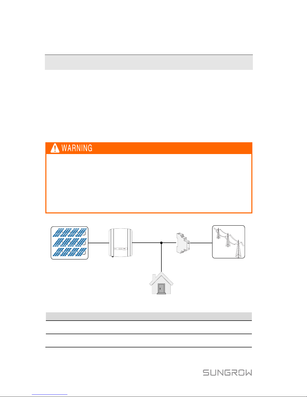
The intended use example is shown in Fig. 2-1.
A B C D
E
Export powerOutput powerPV power
Load power
Fig. 2-1 Application in a PV Power System
Item
Description
Remarks
A PV strings
Monocrystalline silicon, polycrystalline silicon
and thin-film without grounding.
B Inverter
SG2K-S, SG2K5-S, SG3K-S, SG3K-D,
SG5K-D and SG8K-D.
Page 13
User Manual 2 Product Introduction
5
Item
Description
Remarks
C
Sungrow single-phase
or three-phase meter
(optional)
Measures the export power and communicates
with the inverter via an RS485 connection.
D
Utility grid
Grid earthing system types: TT, TN.
E
Household load
Devices that consume energy.
For the TT utility grid, the N line voltage to ground must be 30 V or less.
2.2 Inverter
Type Description
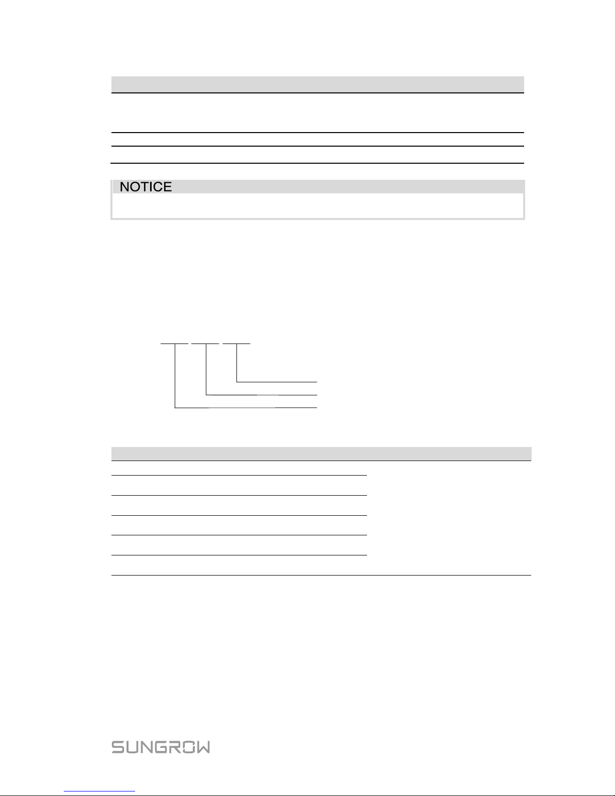
The type description is as foll ow s (take SG3K-S as an example):
SG 3K S
-
S: single MPPT, D: dual MPPTs
Code of power level
Code of PV grid-connected inverter
Tab. 2-1 Power Level Description
Appearance
The image shown here is for reference only. The actual product you receive
may differ.
Type
Nominal Output Power
Nominal Grid Voltage
SG2K-S
2000 W
230 Vac (single phase)
SG2K5-S 2500 W
SG3K-S 3000 W
SG3K-D 3000 W
SG5K-D 4990 W
SG8K-D 8000 W
Page 14
2 Product Introduction User Manual
6
2
3
4
5
61
7
8
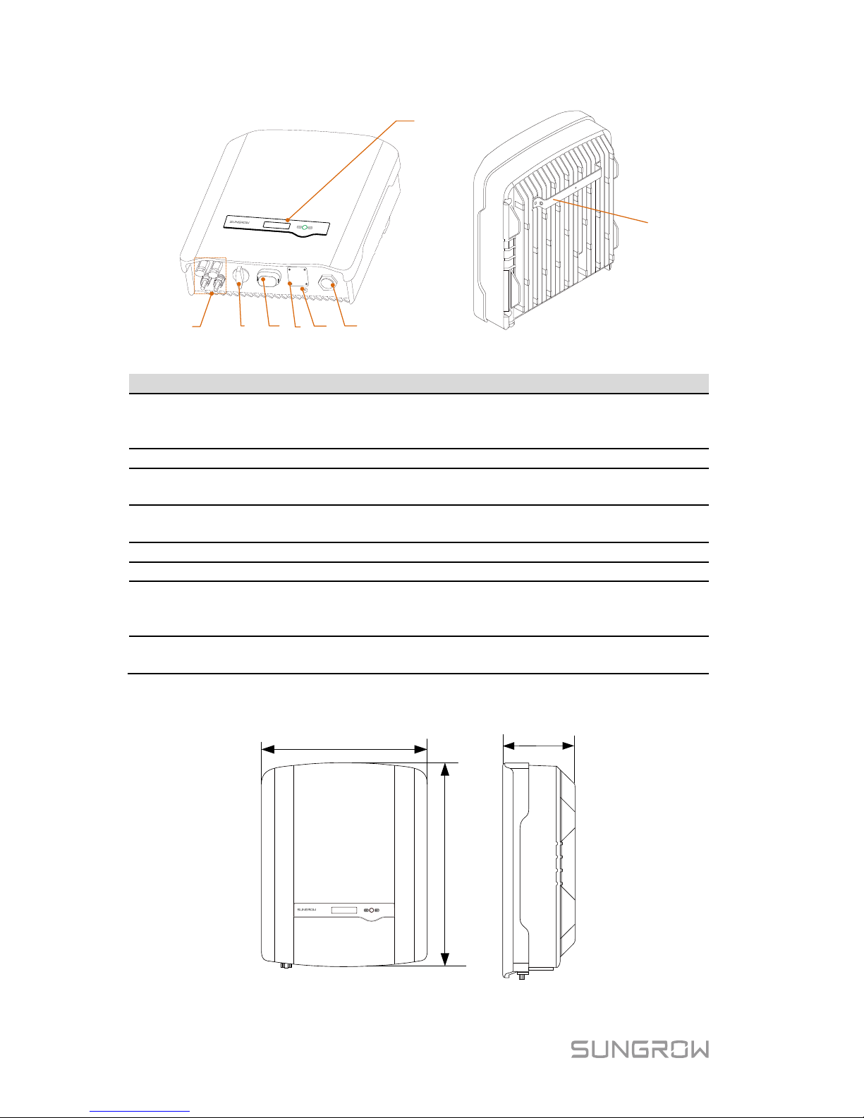
Fig. 2-2 Inverter Appearance (SG5K-D for reference)
Item
Name
Description
1 PV terminals
Positive and negative DC input connectors.
One or two or three pairs, depending on inverter
type.
2
DC switch (optional)
To disconnect the DC current safely.
3 RS485 terminal
To connect the communication module, suc h as
Wi-Fi module.
4
Meter | DRM
terminal
Connections to the energy meter and external
Demand Response Enabling Device (DRED).
5
Second PE terminal
For reliable grounding.
6
AC terminal
To feed power into the utility grid.
7 LCD panel
The display and two buttons can be used to
access current operating data or change inverter
settings.
8 Mounting rack
For mounting the inverter to the wall mounting
bracket.
Dimensions and Weight
W
D
H
Fig. 2-3 Dimensions of the Inverter
Page 15
User Manual 2 Product Introduction
7
Tab. 2-2 Dimensions and Weight
Type
W (mm)
H (mm)
D (mm)
Weight (kg)
SG2K-S / SG2K5-S /
SG3K-S
300 370 125 8.5
SG3K-D / SG5K-D
360
390
133
11.5
SG8K-D
360
390
148
15.5
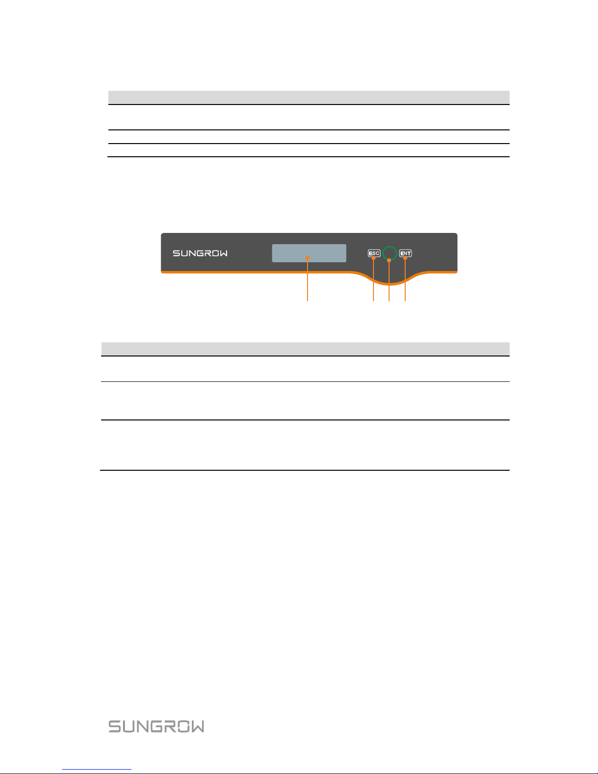
LCD Panel
The LCD panel with a s creen, an indicator and tw o buttons is on the front of t he
inverter.
31 2 2
Fig. 2-4 LCD Panel
No.
Name
Description
1
LCD
screen
Display and access current operating data or change inverter
settings.
2
Buttons
ESC / ENT.
View or set parameters
via the buttons. For detailed
functions, see Tab. 6-1.
3
Indicator
Green / red.
User can observe the colour and blinking frequency to get
the current state of the inverter. For detailed definition, see
Tab. 6-2.
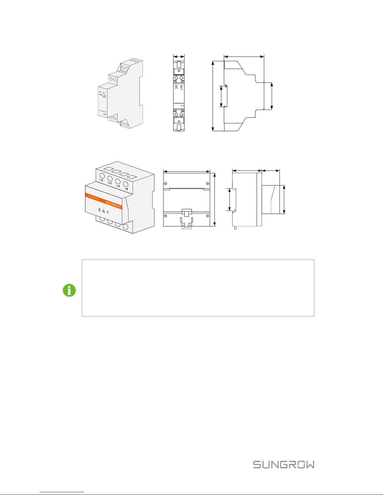
2.3 Energy Meter (optional)
The SUNGROW Ener gy Met er is installed next t o the mai n s wi tc h t o detec t the
electrical measured values at the grid-connected point. It communicates with
the inverter via an RS485 connection. The dimensi ons are shown below.
Page 16
2 Product Introduction User Manual
8
Front view Side view
18
65
117
35
45.3
Fig. 2-5 single-phase Meter Dimensions (unit: mm)
Back view Side view
72
85
45 27
45
35
Fig. 2-6 Three-phase Meter Dimensions (unit: mm)
The single -phase Energy Meter and the three-phase E ner gy Meter
are alternati ve and delivered separatel y. The meter figures in this
document have been created for the single-phase Energy Meter
unless otherwise specified.
More detailed i nf ormat i on on t h e Energy Meter can be found in the
respective Quick Installation Guide.
2.4 Function Description
2.4.1 Basic Function
Conversion function
The inverter converts DC power from the PV array into grid-compliant AC
power and feeds it into the utili ty grid.
Data storage
Inverter logs essential data including running information and error records.
Parameter configuration
Page 17
User Manual 2 Product Introduction
9
Inverter provides various parameter configurations for optimal operation. You
can set the country via t he iSolarCloud App or the cloud server, in case you
require fur ther, please contact Sungrow.
Communicati on interface
You can choose the RS485 terminal for connecting a communication module
to the PV system, such as Wi-Fi module.
It is recommended to use the communication module from
Sungrow. Using a
device from other companies may lead to
communicat ion failure or other unexpected damage.
Further information on the communication module can be found in
the respective Quick Installati on G uide.
Earth fault alarm
If an earth faul t occ urs, the error code will be displayed o n the LCD s creen.
The buzzer inside the inverter wi ll beep to signal an external alarm.
Protective function
The protecti ve functions are integrated in the i nverter, including short c ircuit
protection, grounding insulation resistance surveillance, residual current
protection, anti-islanding protection, DC overvoltage / over-current protection,
etc.
2.4.2 External Demand Response
The inverter provides a RJ45 port for connecting to a demand response
enabling devi ce (DRED) . The DRED ass erts demand respond modes (DR Ms).
The inverter detects and initiates a response to the supported demand
response com mands within 2 s. The f ollowing table lis ts the DRMs support ed
by the invert er.
Tab. 2-3 Demand Respons e Modes (DRMs)
Mode
Explanation
DRM0
The inverter is in the state of standby.
DRM5
The export power to the grid is 0.
DRM6
The export power to the grid is no more than 50% of the rated power.
DRM7
The export power to the grid is no more than 75% of the rated power.
DRM8
The export power to the grid is 100% of the rated power, but subject
to the constraints from other active DRMs.
Page 18

2 Product Introduction User Manual
10
2.4.3 Reactive Power Regulation
The inverter i s capable of opera ting in reac tive power r egulation modes for the
purpose of providing support to the grid. These various operating modes can be
enabled or disabled via the LCD menu.
PF: Fixed power factor mode.
Qt: Fixed reactive power mode.
Q(p): The PF of t he inverter output varies in response to the output power of
the inverter.
Q(u): The reac tive power output of the inverter var ies in response to t he grid
voltage.
2.4.4 Power Quality Respons e
The inverter supports two power quali ty response modes.
Power response for voltage variations
Define the res ponse curve with f our reference voltages , which can be set via
the LCD menu. The power output will vary in response to the voltage curve.
Refer to “7.5.2 Setting Protect ive Parameters” for detail s.
Power response for frequency variat ions
The inverter provides built -in over/under frequency protective threshold values.
Refer to “Tab. 7-7 Protective Parameters of Grid Standards” for details.
When the grid f requency is lower t han the under-f requency l imit or hi gher than
the over-frequency limit, the inverter will be disc onnected from the grid.
When there is an increase in grid frequency which exceeds 50.25 Hz, the
inverter wi ll r educe t he power output l inear ly w it h an incr eas e of freque nc y unti l
the end value (52.00 Hz) is reached.
Page 19
11
3 Unpacking and Storage
3.1 Unpacking and Inspection
The inverter is thoroughly tested and strictly inspected before delivery. Damage
may still occ ur during shipping. Cond uct a thorough inspecti on after receiving
the device.
1. Check the pack aging for any visible damage.
2. Check the inner contents for damage after unpac king.
3. Check the delivery contents for completeness according to the
packaging list.
Contact SUNGROW or the distributor in case of any damaged or missing
components.
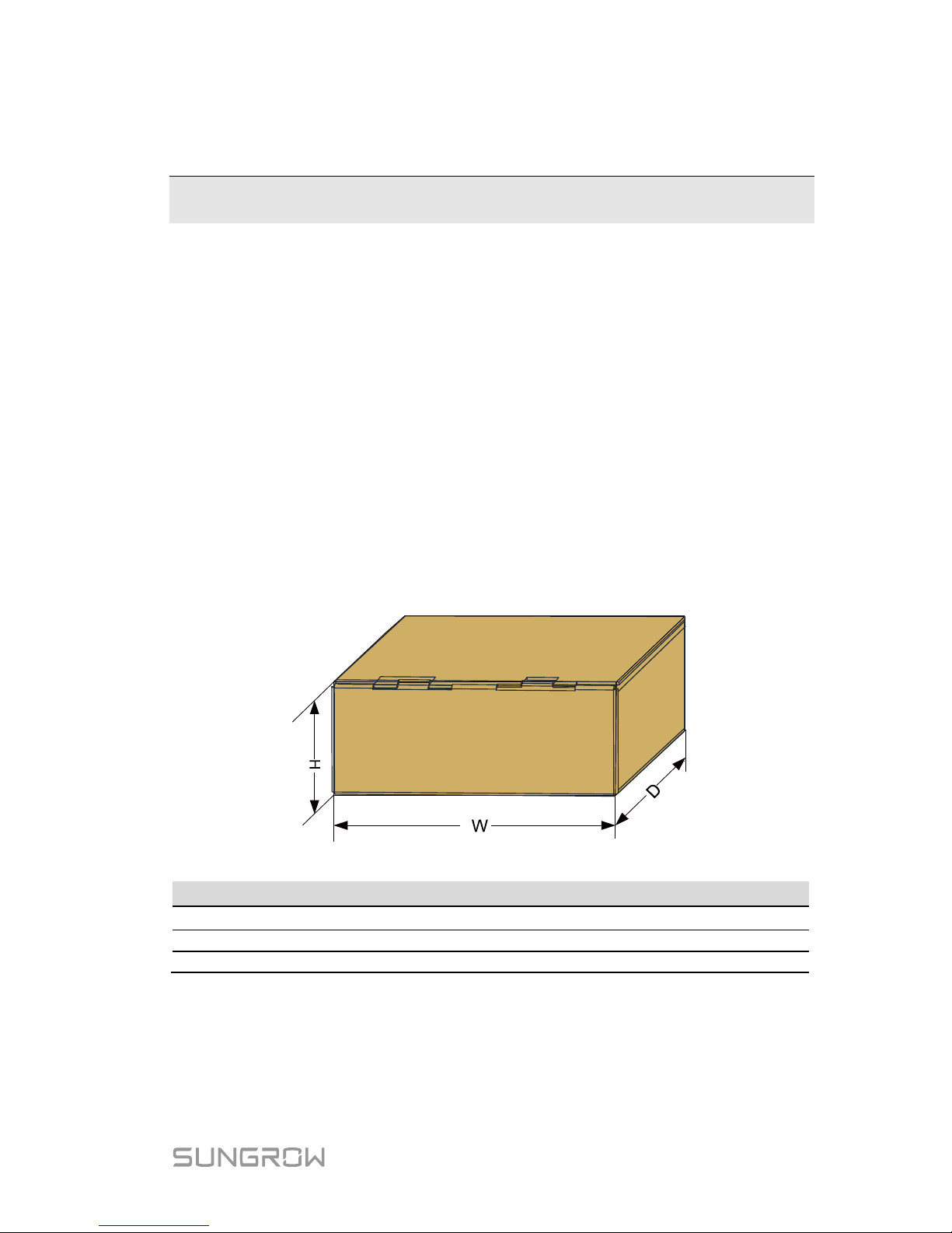
It is the best choic e to store the inverter in the origi nal packaging. So, do not
dispose of i t.
Fig. 3-1 Single Inverter Packaging
Inverter Type
W (mm)
H (mm)
D (mm)
SG2K-S / SG2K5-S / SG3K-S
500
235
375
SG3K-D / SG5K-D
530
235
435
SG8K-D
530
250
435
Page 20
3 Unpacking and Storage User Manual
12
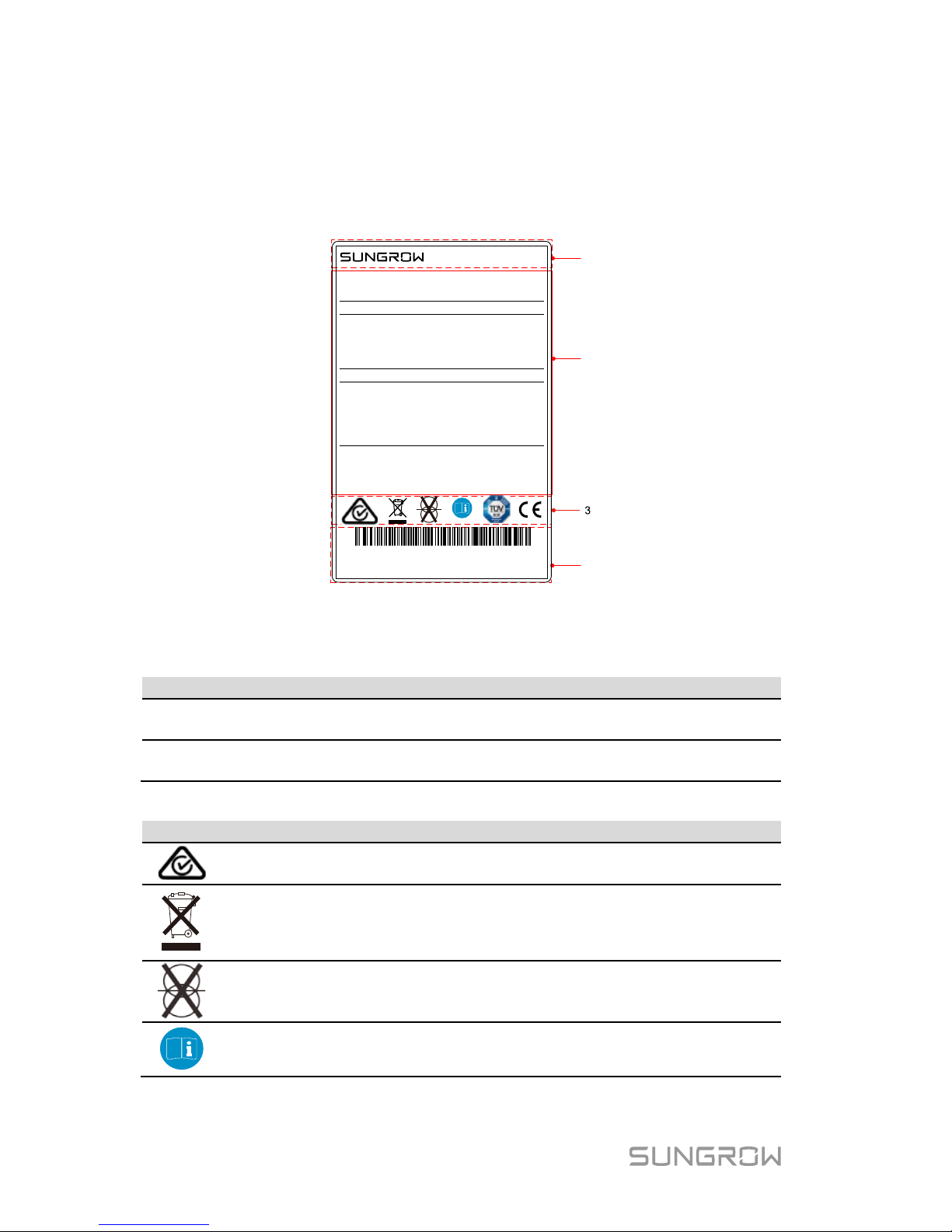
3.2 Identifying the Inverter
The nameplate clearly identifies the product. It is attached to the side of the
inverter.
1
2
4
工 作 温 度 范 围
型号
M od e l
S/ N
序列号
D C -I np ut
直流输入
最大输入电压
Min. MPP Voltage
最小 MPP 电压
Max. MPP Voltage
最大 MPP 电压
Max. Input Current
最大输入电流
Isc PV
最大短路电流
A C-Output
交流输出
额定输出电压
额定输出频率
Rated Output Power
额定输出功率
Max. Output Current
最大输出电流
Max. Apparent Power
最大视在功率
Power Factor Range
功率因数范围
安全等级
过压等级
防护等级
w ww. s un g ro w po w er. co m
S U N GR O W P O W E R S U P PL Y CO . ,L T D.
中 国 制 造
M ad e i n C h in a
阳 光 电 源 股 份 有 限 公 司
SG5K-D
D C
D C
D C
D C
II I[A C ], I I[ D C]
D C
A**********
Password
密码
********
600 V
90 V
560 V
20(10/10)A
24(12/12)A
230 V
50 Hz
AC 21.7 A
4.99 kW
4.99 kVA
I
IP65
-25℃…60℃
光 伏 并 网 逆 变 器
G R ID - C O N NE C T E D IN VE R T E R
0.8 Lead...0.8 Lag
Max. Input Voltage
Rated Output Voltage
Rated Output Frequency
Safety Class
Overvoltage Category
Enclosure
Ambient Temperature
P V
Fig. 3-2 Nameplate of Inverter
* The image shown her e is for referenc e only. The actual pro duct you rec eive
may differ.
Item
Description
Item
Description
1
SUNGROW logo and product
type
3
Marks of certification
institutions
2 Technical data 4
Barcode, company name and
origin
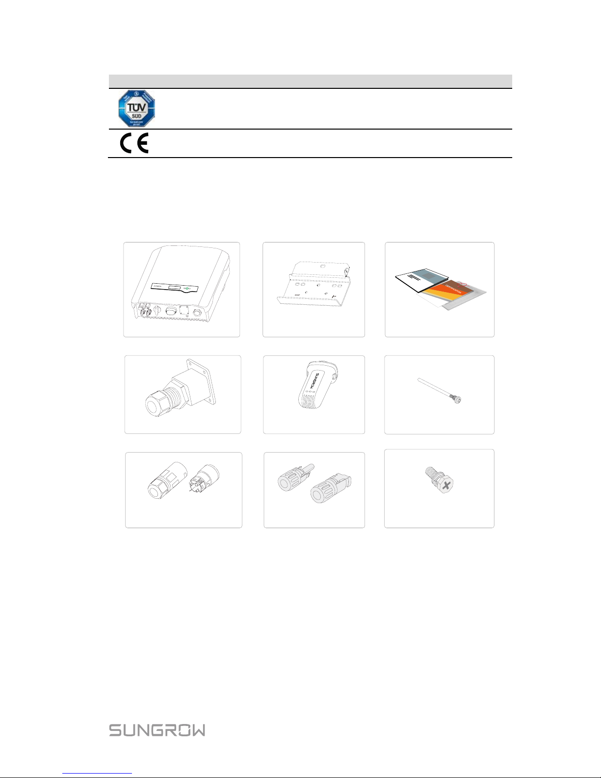
Tab. 3-1 Descri ption of Icons on the Nameplate
Icon
Description
Regulatory compliance mark.
Do not dispose of the inverter together with household waste.
The inverter does not have a transformer.
Refer to the corres pondi ng i nst ructions .
Page 21
User Manual 3 Unpacking and Storage
13
Icon
Description
TÜV mark of conformity.
CE mark of conformity.
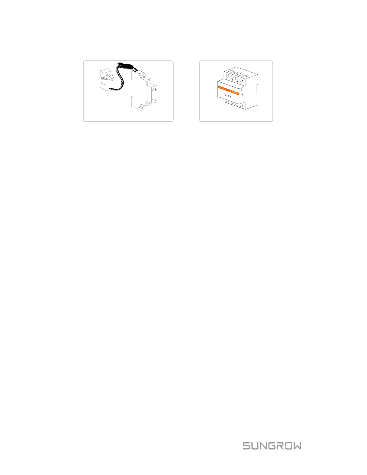
3.3 Delivery Contents
Standard Delivery
Inverter
Wall-mounting bracket
Communication connector
Documents
M4x80 screw set
b
PV connector set
b
AC connector set
Wi-Fi module
M4x10 grounding screw
c
a
Fig. 3-3 Delivery Contents
a) The inverter figures in this document have been created for SG5K-D
unless otherwise specified.
b) The documents include the Quick User Manual, quality certificates,
packaging lis t and product test reports.
c) One or tw o or three pairs, dependi ng on inverter type.
Page 22
3 Unpacking and Storage User Manual
14
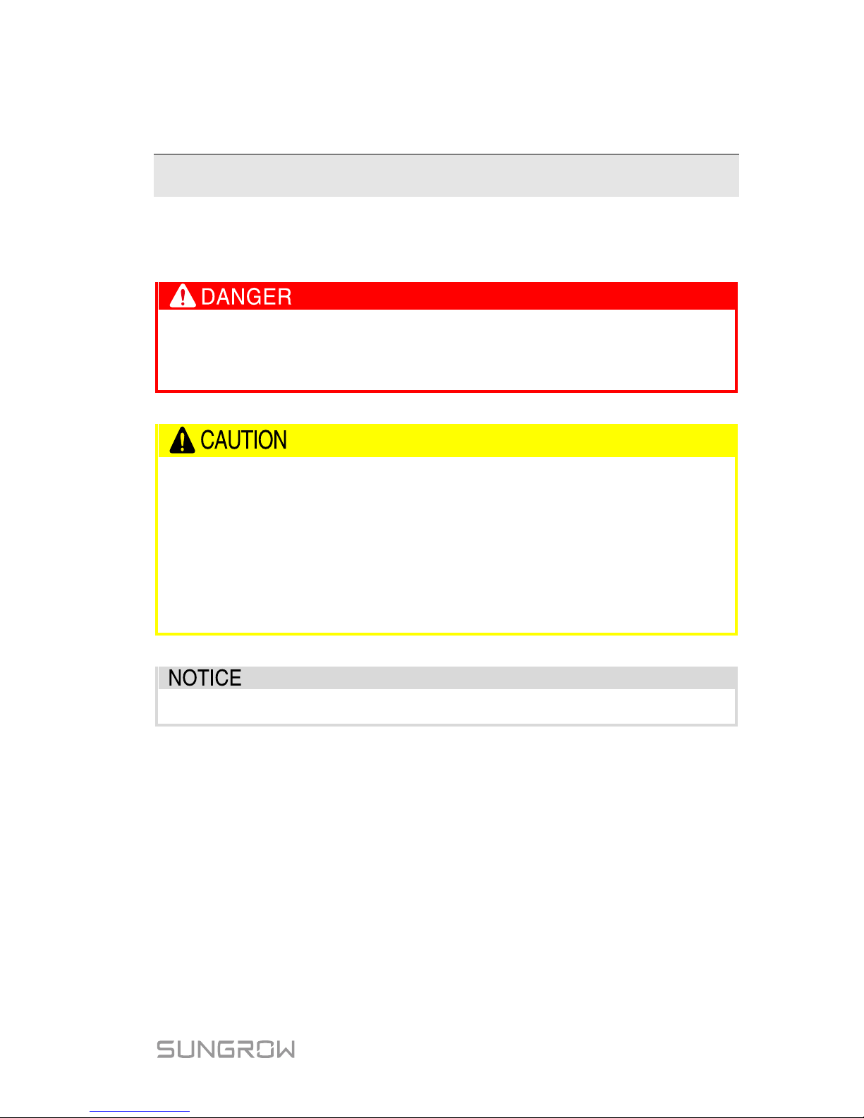
Optional Accessory
Single-phase meter
Three-phase meter
The single-phase Energy Meter and the three-phase Energy Meter are
optional. The meter figures in this document have been created for the
single-phase E nergy Meter unless otherwise specified.
The Energy Meter is not included in the i nverter packaging but, if ordered,
delivered separ ately.
3.4 Storage of Inverter
If you do not install the i nverter imm ediately, choose an appro priate l ocation t o
store it.
Store the inverter in the original packaging with the desiccant inside.
The storage t emperature should be alw ays between -30°C and +85°C, and
the storage relative humidity should be always between 0 and 100 %,
non-condensing.
When storing inverters, do not stack more than 8 inverter packages on top of
each other.
The packaging should be upright.
Page 23
15
4 Mechanical Mounting
4.1 Safety during Mounting
Make sure ther e is no electrical connection before installati o n.
In order to avoid electric shock or other injury,
be sure there is no
electricity or plumbing installations before drilling holes.
Risk of injury due to im proper handling
The weight can cause injuries, serious wounds, or bruise.
Always follow the instructions when moving
and positioning the
inverter.
System perfor mance loss due to bad ventilation!
The inverter requires good ventilation during operation. Keep it
upright and nothing co vering the heat sink.
Wear gloves to avoid scratches when mounting the inverter.
4.2 Location Requirements
The inverter with IP65 can be installed indoors or outdoors.
Selecting an optimal location for the inverter is critical for its operating safety as
well as the e xpected effi ciency and s ervice l ife. Considerations for the locat ion
include:
1. The structure should be capabl e of withstanding a f orce of four times the
weight of the inverter and be suitable f or the dimensions of the inverter.
2. Install the inverter where it is convenient for installation, cable connection
and service.
Page 24
4 Mechanical Mou nt in g User Manual
16
3. Do not install the inverter in the living area or bedrooms. The noise
during its operation may affect daily l ife.
4. The location should be not accessible to children.
5. The ambient temperature and relative humidity should meet the following
requirements.
Max.
+60°C
Min.
-25°C
Max. RH
+100%
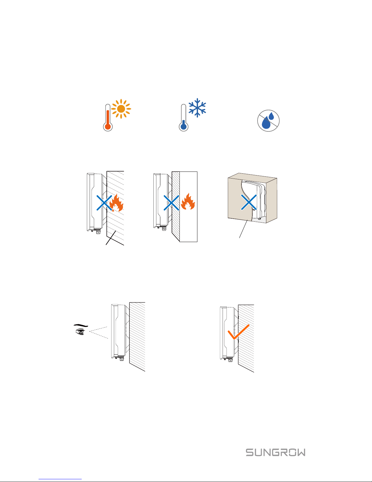
6. Only mount the inverter on a non-flammable surface or a wooden
structur e. Keep away from flamm able materials or gas. Do not enclose
the inverter into a tight confinem ent.
Enclosed cabinet
Flammable wall
Flammable material or
gas near the installation
7. The shaded side of the building woul d be better to preve nt the inverter
from exposure to the sun, rain, and s now.
8. Install at eye level for easy
inspection.
9. Install vertically for good heat
dissipation.
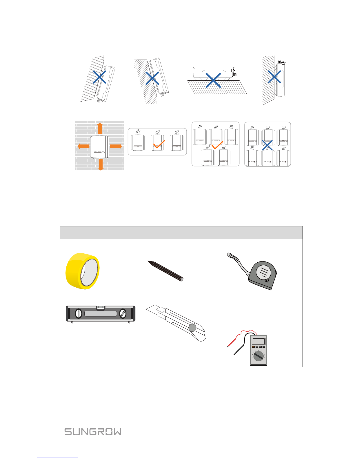
10. Never install the inverter horizontally, or with a forward tilt or with a
backward ti lt or even with upside down. T he horizontal installat ion can
result i n dam age to the inverter.
Page 25
User Manual 4 Mechanical Mou nt in g
17
Forward tilt Backward tilt
Horizontally
Upside down
11. Clearance requirement and multiple installation:
400 mm 400 mm
400 mm
800 mm
For multi-r ow i ns tall ation, the di s tance bet we en two ad jac ent r ow s shoul d be at
least 400 mm.
4.3 Tools
General tools (recommended)
Packaging tape
Marker
Measuring tape
Level
Utility knife
Multimeter
Measurement range: ≥
1100Vdc
880.0
Page 26
4 Mechanical Mou nt in g User Manual
18
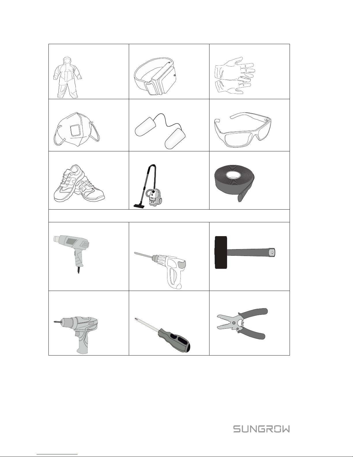
Protecti ve clothing
Wrist st rap
Protecti ve gloves
Dust mask
Earplugs
Goggles
Insulated s hoes
Vacuum cleaner
Heat shrink tubing
Installation tools (recommended)
Heat gun
Hammer dril l
Drill bit: φ10
Rubber mallet
Electric screwdriver
Tool bit: M4
Phillips sc rewdriver
Specification: M4
Wire stripper
Page 27
User Manual 4 Mechanical Mou nt in g
19
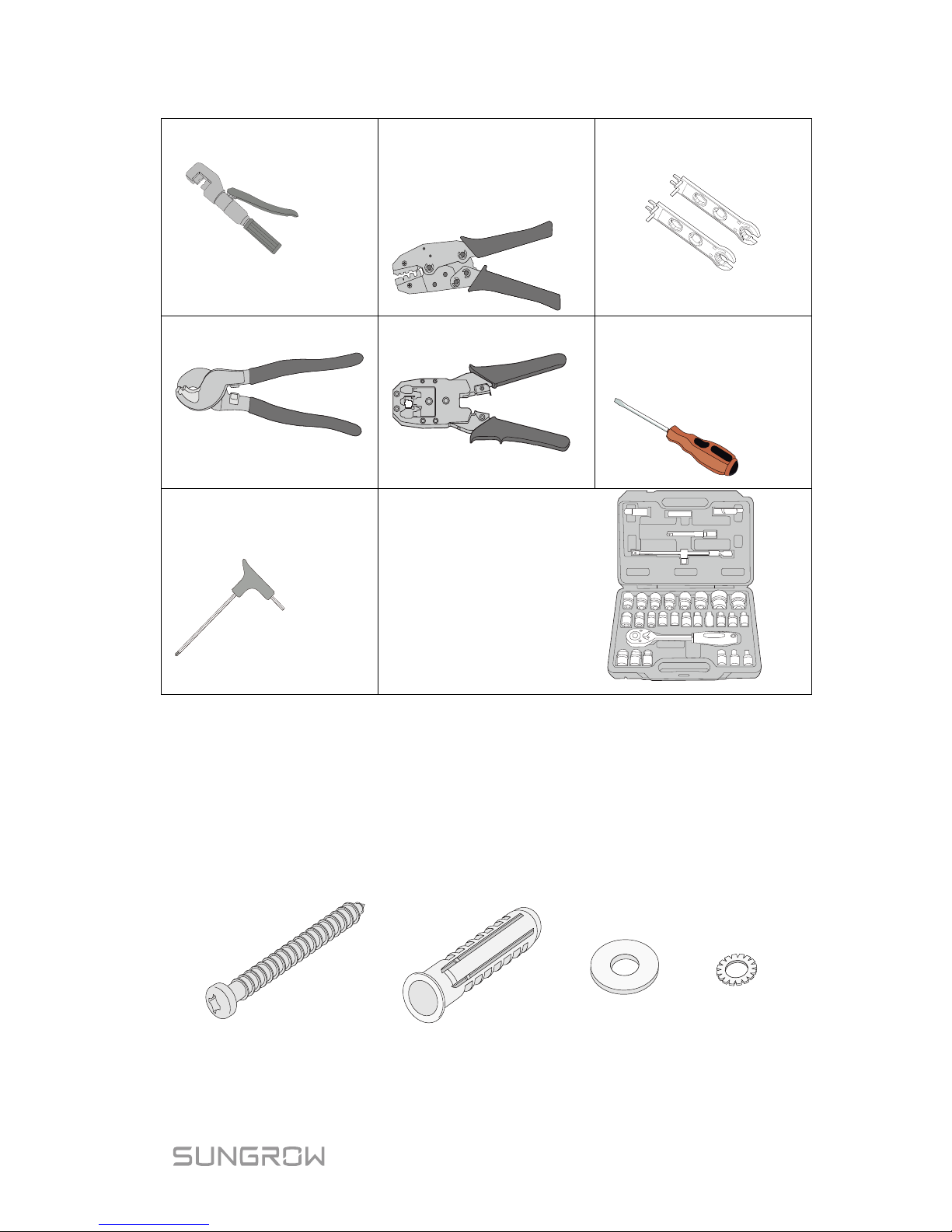
Hydraulic pl ier
Wire crim per
Crimping range:
2.5-6mm²
Wrench for MC4
terminal
Wire clipper
RJ11 crimping tool
Flat-blade screwdriver
M4
Torx screwdriver
TX30
Socket wrench
Open end:
10mm (for
M6 bolts)
13mm (for M8 bolts)
16mm (for M10 bolts)
4.4 Installing the Inverter
Inverter is installed on the wall by means of wall-mounting bracket and the
expansion plug sets.
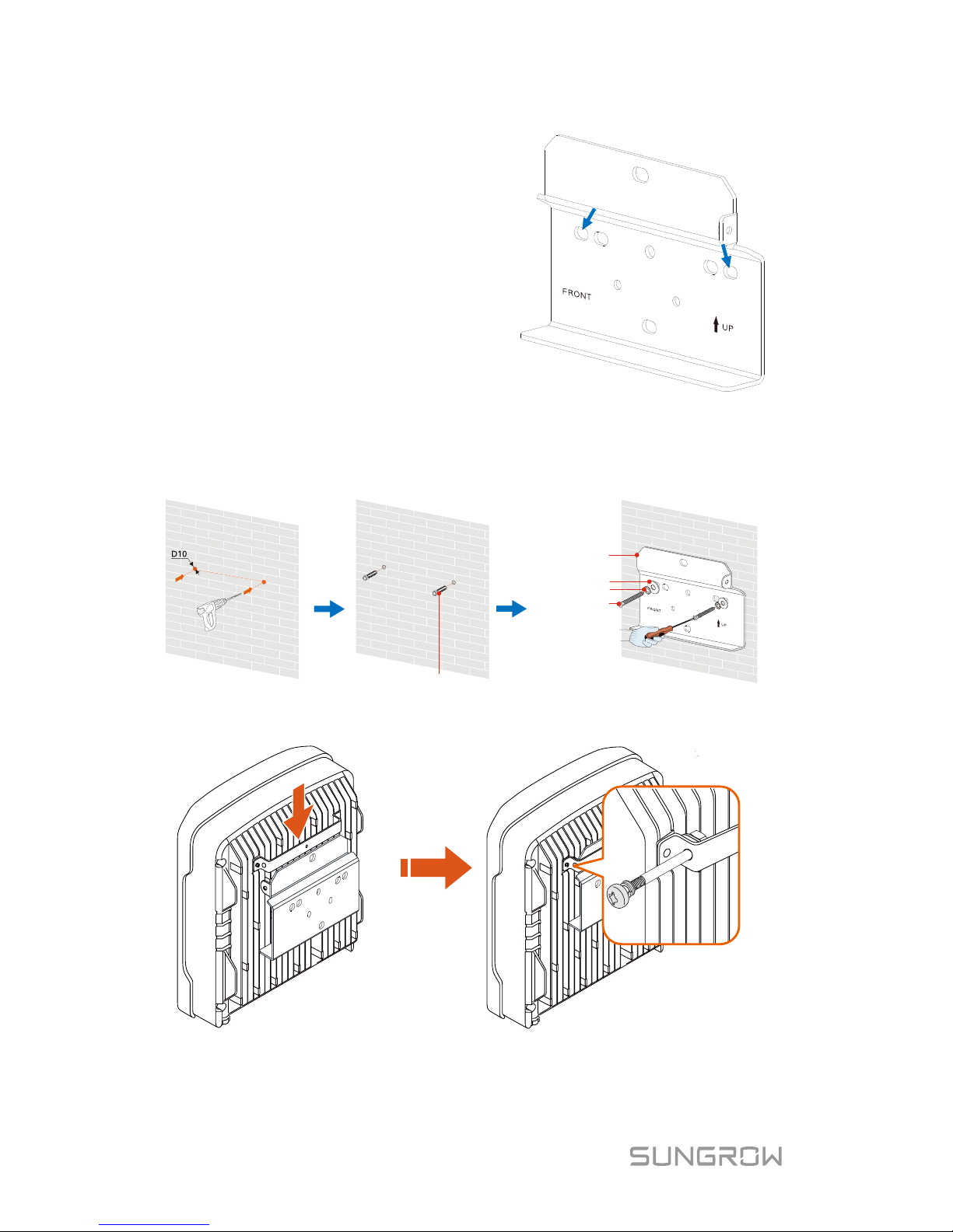
The expansion plug set s hown below i s r ec ommended f or t he install ati on. They
are not incl uded in the delivery sc ope.
Stainless steel screw M6 Spring washerFender washerExpansion tube
Page 28
4 Mechanical Mou nt in g User Manual
20
1. Align the wall mo unti ng brac k et
horizontally on t he wall with the
arrow upwards. M
ark the
position of the drill holes. Use
at least one hole on the rightand left-hand side of the wall
mounting bracket.
Tip: When mounting on a post,
use the upper and lower central
holes of the wall mounting
bracket.
2. Set the wall mounting bracket aside and drill the marked holes. The
depth of the holes should be about 70 mm. Install the wall-mounting
bracket.
Wall-mounting bracket
Fender washer
Spring washer
Self-tapping screw
Expansion tube
3. Mount the inverter to the bracket, and secure it with an M4x80 screw
(torque: 1.5 Nm).
Page 29
User Manual 4 Mechanical Mou nt in g
21
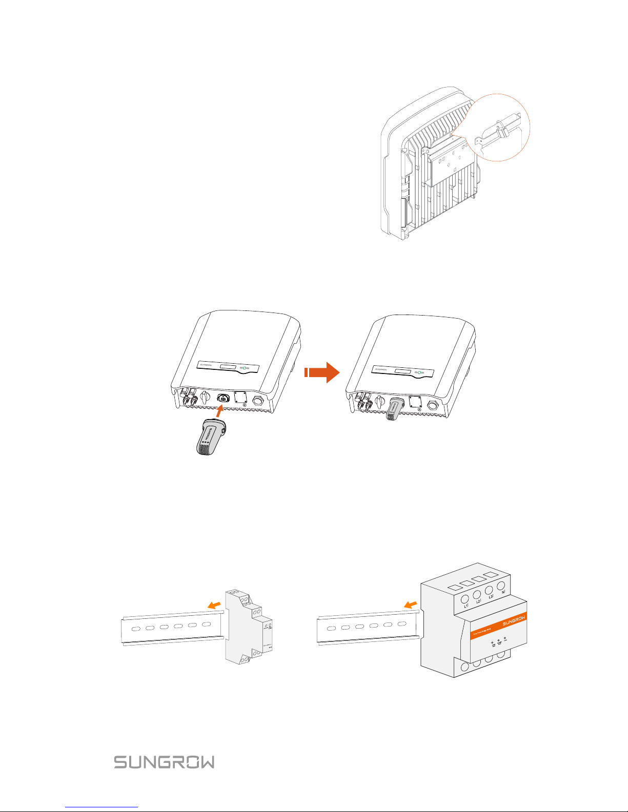
4. To protect the inverter from
theft, you can lock it with a
padlock. The padlock is
purchased by the user if
necessary. The hole diameter
is about 8 mm.
5. Remove the waterproof lid from RS485 terminal and install the
communication module to the inverter. The following figure takes the
Wi-Fi module as an example. Refer to the manual delivered with the
module for details.
4.5 Installing the Energy Meter
The SUNGROW Energy Meter should be installed between the grid and the
load. It supports a 35 mm DIN-rail installation, as shown in the following figure.
Single-phase Energy Meter
Three-phase Energy Meter
Fig. 4-1 Installing the Meter to the Rail
Page 30
22
5 Electrical Connection
Prior to any electrical connections, keep in mind that the inverter has dual
power supplies. It is mandatory for the technical personnel to wear personal
protecti ve equipments (PPE) duri ng the electrical w ork.
Danger to life due to a high voltage inside the inverter
Make sure that the cables are not live before electrical connection.
Do not turn on the AC circuit breaker until all the electrical
connections ar e completed.
Improper operation dur ing the wir ing process can caus e fatal injury to
the operators o r unrecoverable damage to the inverter.
Only qualified personnel can perform the wiring wor k.
All cables must be fi rm ly attached, undam age d, pr operly insulated and
adequately dim ensioned.
Comply with t he safety instructions relat ed to the PV strings and the
regulations relat ed to the utility grid.
All electrical connections must be in accordance with local and
national standards.
Only with the permission of the utility grid, the inverter can be
connected to the utility grid.
Electrical connections of the inverter include grounding, PV connection, AC
connection and communication c onnection.
Page 31
User Manual 5 Electrical Connection
23
A
B
C
D
L
N
PE
PE
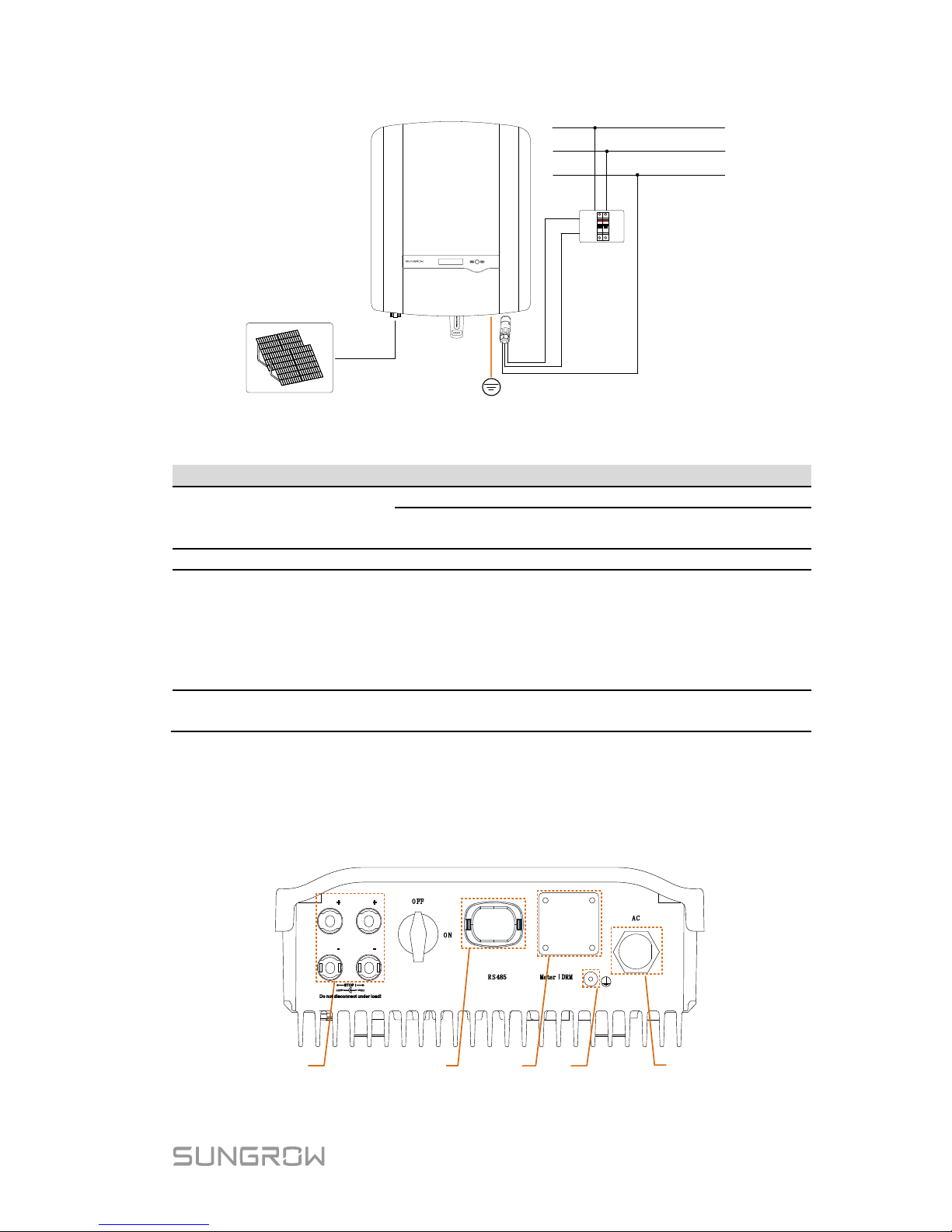
Fig. 5-1 Electrical Connection Diagram
Item
Name
Remarks
A PV strings
-S series: one pair of PV terminals.
-D series: three pairs for SG8K-D and two pairs for
other –D inverters.
B
Wi-Fi module
RS485 communication.
C
AC circuit
breaker
Used as a protective device during electrical
connection. User equips this device according to
the maximum output voltage and current.
The PE wire of the AC terminal must be directly
connected to the grounding bar. Do not connect it to
protection devices such as the circuit breaker.
D Utility grid
Nominal line-to-neutral voltage of the utility grid is
230 Vac.
5.1 Terminal Description
All elect rical terminals ar e located at the bottom of the inverter.
1 2
53
4
PV2
PV
2
PV1
PV1
Fig. 5-2 Terminal Description
Page 32
5 Electrical Connection User Manual
24
* Image shown here is for r eference only. The actual product you r eceive may
differ.
Tab. 5-1 Terminal Descriptions
Item
Terminal
Description
1 PV terminals
MC4 terminals for PV inputs.
-S series: one pair of PV terminals.
-D series: t hree pairs for SG8K-D and two pairs
for other –D inverters.
2
RS485 terminal
To connect a Wi-Fi module.
3
Meter | DRM
terminal
The left hole is for meter communication and the
right is for DRED communication.
4
Second PE terminal
For reliable grounding.
5
AC terminal
The AC terminal to the utility grid.
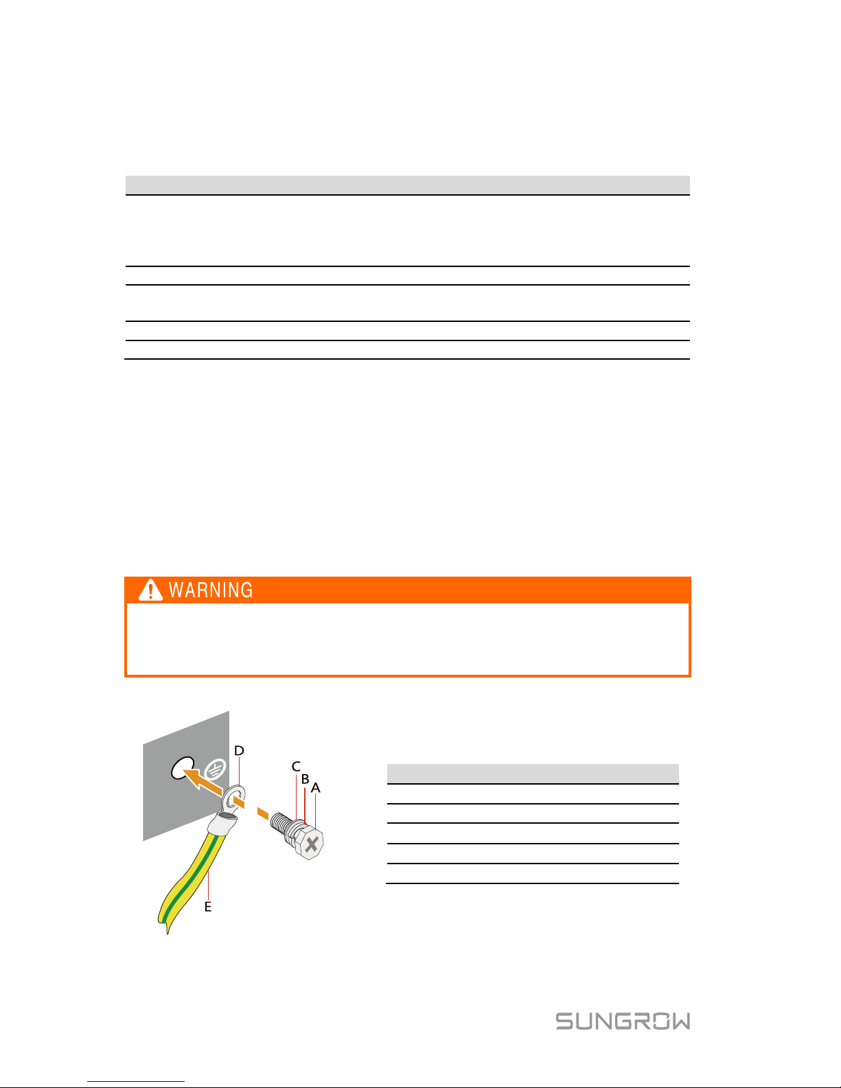
5.2 Grounding the Inverter
All non-current carrying exposed metal parts of the equipment and other
enclosures in the PV power s ystem s hould b e ground ed, e.g. PV s tr ings frame
and inverter enclosure.
A second Protective Earth (PE) terminal is equipped at the bottom of the
inverter. Be sure to connect this PE terminal for reliabl e grounding and ensure
that the groun ding resistance is less than 10 Ohm.
Correct grounding connection of the second PE terminal and the AC
terminal is mandatory. Not properly connecting both PE will void any or
all product warranty.
Item
Description
A
Screw (M4×10 mm, 1.5 Nm)
B
Spring washer
C
Washer
D
Cable socket
E
Grounding cable
Fig. 5-3 Second PE Connection
Page 33
User Manual 5 Electrical Connection
25
* The second PE conductor should be of the same cross-sectional area as the
original PE c onductor in the A C connec tor. The cable and cable soc ket are not
included in the delivery scope.
5.3 Grid Connection
The inverter is connected to the grid via 3 wires (L , N and PE).
Inverter is equipped with the waterproof direct plug-in connector which matches
the AC terminal at the bottom of the inverter.
5.3.1 AC Side Requirements
AC Circuit Breaker
An independent t wo-pole AC circui t br eak er for the inverter must be ins tall ed at
the output s ide f or saf e disconnection. The recommended speci fi c ati ons are as
follows:
Inverter Type
Specification
SG2K-S / SG2K5-S / SG3K-S / SG3K-D
25 A
SG5K-D
32 A
SG8K-D
50 A
In PV systems with multiple inverters, protect each inverter with a
separate circuit breaker. This will
prevent any residual voltage from
being present at the corresponding cable after disconnection.
Residual Current Device
With an integrated universal current-sensitive r esidual current monitoring unit
inside, the i nverter will disconnect immediately fr om the mains power as soon
as a fault c urrent with a value exceedi ng the limit has been detected.
However if an e xternal res idual c urrent device ( RCD) is mandatory, the switc h
must be triggered at a residual current of 300 mA or higher.
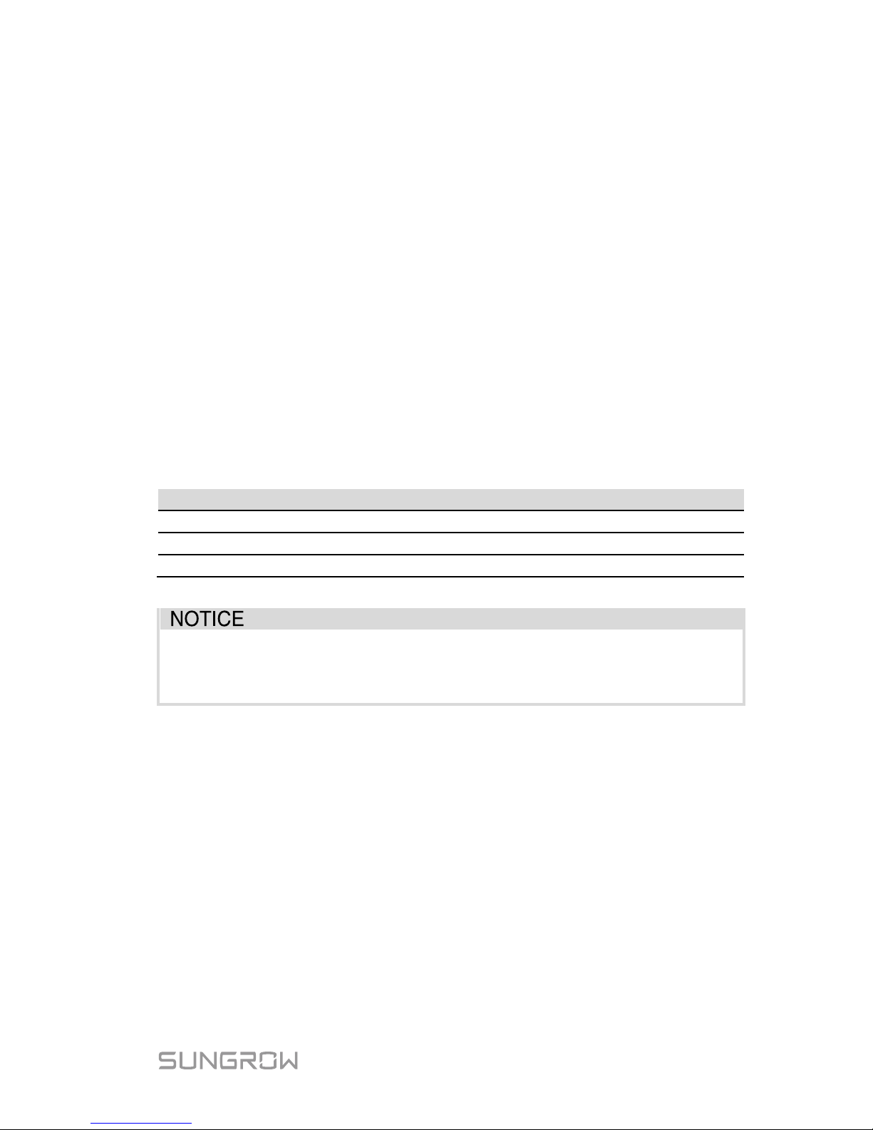
AC Cable Requirements
The recommended specifications are shown in the fol lowing table
Page 34
5 Electrical Connection User Manual
26
Type
Cross-section (mm²)
Cable diameter (mm)
Range Recommended Range
Recommende
d
SG2K-S / SG2K5-S /
SG3K-S / SG3K-D
4…6 4 10…14 14
SG5K-D
4…6
6
10…14
14
SG8K-D
- 6 -
15
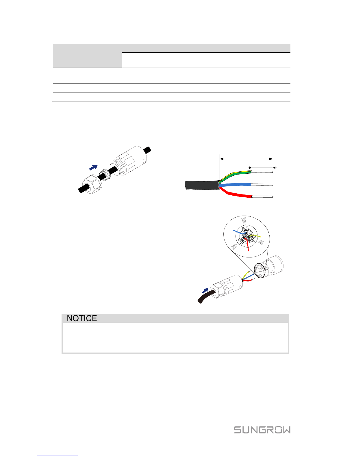
5.3.2 Assembling the AC Connector
1. Lead the AC cable t hrough the
cable gland and the housing.
2. Remove the cabl e jacket by
40 mm, and strip the wire
insulation by 8-15 mm.
8-15 mm
PE
L
N
40 mm
3. Fully insert the conductors to
the corresponding terminal
and tighten the screws with
the torque 0.8 Nm
. Pull
cables outward to check
whether they are firmly
installed.
Observe the terminal layout of AC connector. Do not connect the
phase lines to “PE” terminal, otherwise the inverter will not function
properly and the loss of any or all the warranty rights may follow.
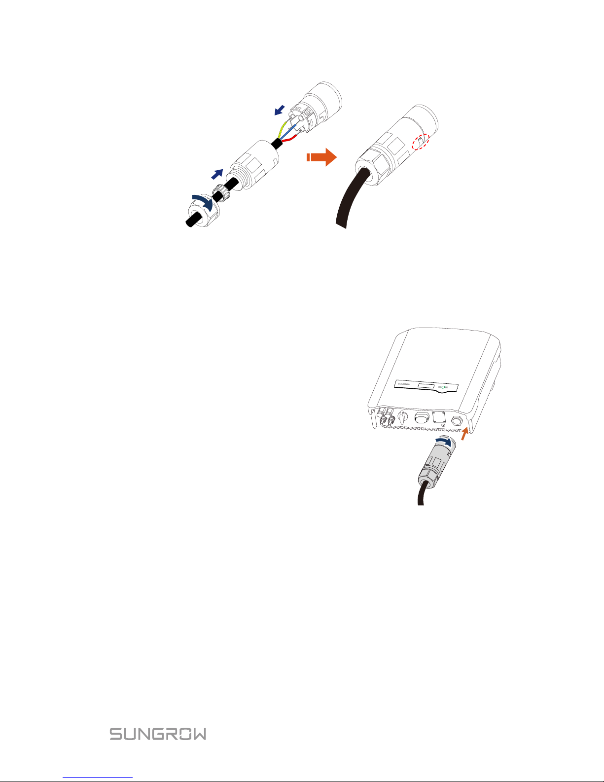
4. Assemble the housing, the terminal block and cable gland. Make sure
that the rib of the terminal block and the groove on the housing
engage perfectly until a “Click” is heard or felt.
Page 35
User Manual 5 Electrical Connection
27
5.3.3 Installing the AC Connector
1. Disconnect the AC circuit breaker and secure it agains t reconnection.
2. Measure the voltage and frequency of the grid-connected point to ensure
that they are wi thin the specified range listed in “10.1 Technical Data”.
3. Align the AC connector and the AC
terminal and mate them together by
hand.
Tighten the connector to the
terminal until a “Click” is heard or felt.
4. Connect the other ends. Connect “PE” conductor to the grounding
electrode. Connect “L” and “N” conductors to the AC circuit br eaker.
5. Pull all the lines outward to check whether they are fir m ly installed.
Page 36
5 Electrical Connection User Manual
28
5.4 PV Connection
There is a ri sk of inverter damage! T he following r equirements should
be met. Fail ure to do so will void guarantee and warranty claims.
Make sure that the maximum sho rt circuit current of each DC input is
less than inverter allowable limit.
Make sure t hat the m axim um open v ol tage of each st r ing is l ess than
600 V. Voltage over 600 V can d am age the inverter.
Make sure that the impedances between the posi tive terminal of the
PV string and Earth, and the impedances between the negative
terminal of the PV string and Earth are larger than 200 kΩ in any
case.
5.4.1 PV Input Configuration
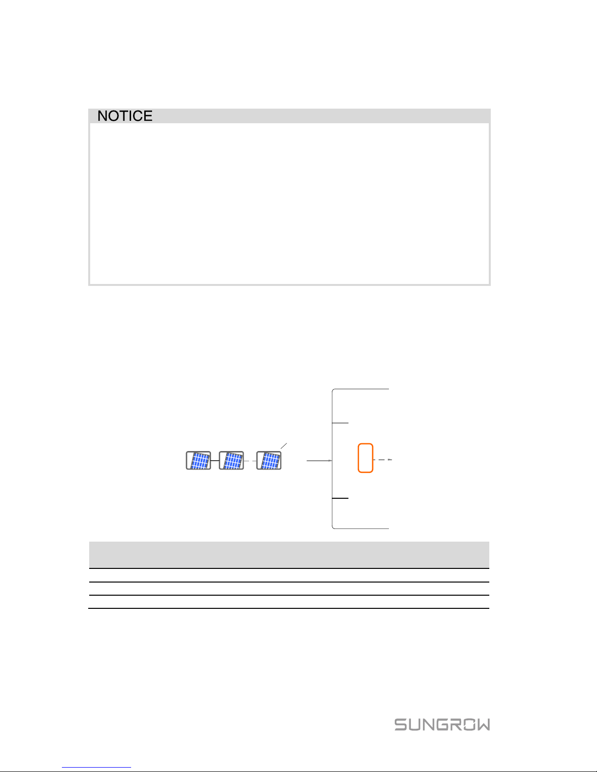
-S Series
There is one input area with one MPP tracker. Only one input can be connected,
as shown in the following figure.
PV input
MPPT
Inverter inside
Type
Total PV Input
Power Limit
Open-circuit
Voltage Limit
Short-circuit
Current Limit
SG2K-S
3000 W
600 V
12 A
SG2K5-S
3200 W
600 V
12 A
SG3K-S
4000 W
600 V
12 A
-D Series
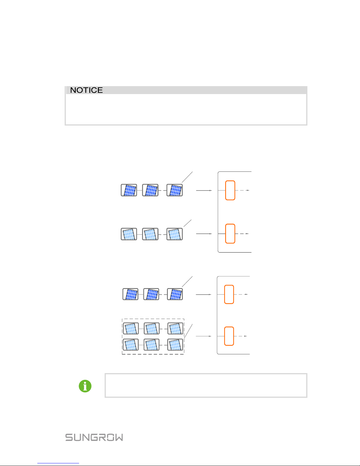
For –D inverter s except SG8K-D, there are two pairs of PV terminals, each with
its MPP tracker.
Page 37
User Manual 5 Electrical Connection
29
The inverter SG8K-D has three pairs of PV terminals. The PV1 has an
independent MPP tracker. The PV2 has two pairs of PV terminals , which are
internal paralleled and with one MPP tracker.
The PV1 and PV2 c an be configured in inde pendent mode or parallel mode.
For SG8K-D, the PV strings to PV2 input
should have the same PV
module type, the same string length, identic
al tilt and identical
orientation.
Independent Mode
The two PV inputs wor k independently, each with its own MPPT. The two PV
inputs can be different from each other in PV module types, numbers of PV
panels in PV string, tilt angles and orientation angle of PV modules.
MPPT2MPPT1
Inverter Inside
PV input 1
PV input 2
Fig. 5-4 Independent Mode for –D inverters except SG8K-D
MPPT2MPPT1
Inverter Inside
PV input 1
PV input 2
Fig. 5-5 Independent Mode for SG8K-D
Only the current is limited for a single input and the power is not
limited.
Prior to connec ting the invert er to PV inputs, the spec ifications in t he following
table should be met:
Page 38
5 Electrical Connection User Manual
30
Type
Total PV Input
Power Limit
Open-circuit
Voltage Limit
(PV1 / PV2)
Short-circuit
Current Limit
(PV1 / PV2)
SG3K-D
4000 W
600 V/600 V
12 A/12 A
SG5K-D
6500 W
600 V/600 V
12 A/12 A
SG8K-D
10400 W
600 V / 600 V / 600 V
15 A / 15 A / 15 A
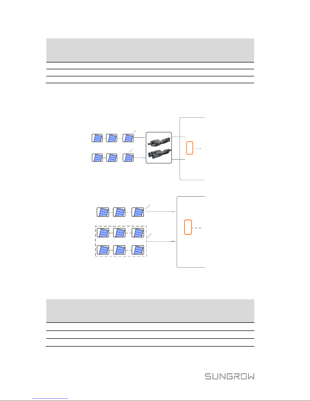
Parallel Mode
All PV str ings should have t he same PV module t ype, the sam e string l ength,
identical tilt and identical orientation for optimum results.
PV input 1
PV input 2
MPPT
Inverter inside
Fig. 5-6 Parallel Mode for –D inverters except SG8K-D
PV input 1
PV input
2
MPPT
Inverter inside
Fig. 5-7 Parallel Mode for SG8K-D
Prior to connec ting the invert er to PV inputs, the spec ifications in the following
table should be met:
Type
Total PV Input
Power Limit
Open-circuit
Voltage Limit
Short-circuit
Current Limit
SG3K-D
4000 W
600 V
24 A
SG5K-D
6500 W
600 V
24 A
SG8K-D
10400 W
600 V
45 A
Page 39
User Manual 5 Electrical Connection
31
To avoid the
input power unbalance of the two inputs or input
load-restriction, ensure the two PV input cables are of the same type.
5.4.2 Assembling the PV Connector
All PV cables are equipped wi th the water-proof direct plug-in connectors which
match the PV t erminals at the bottom of the inverter.
The PV cables mu st be multi-stranded wires.
To ensure the protection degree IP65, only use the connectors
delivered or connectors with the same degree of protection.
The requirements of PV cables are as follows.
Cross-section
Cable Diameter
Max. Withst and
Voltage
Max. Withst and
Current
4 mm2–6 mm2 6 mm–9 mm 600 V
Same with
short-circuit
current
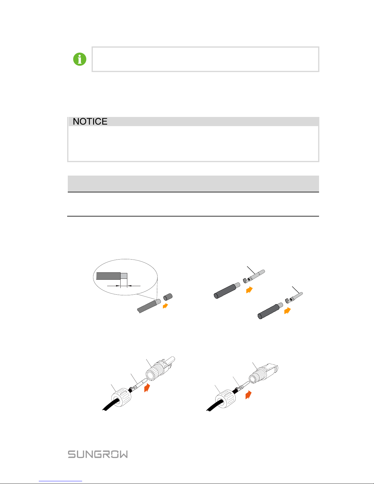
Procedure:
1. Strip the insulation from the cables
by 7 mm.
7
mm
2. Assemble the cable ends
by crimping pliers.
Positive Crimp Contact
Negative Crimp Contact
3. Lead the cable throug h cable gl and, and ins ert into t he insul ator unti l it
snaps into place. Then tighten the cable gland (torque 2.5 Nm to 3
Nm).
Crimp Contact
Positive Insulator
Cable Gland
Crimp Contact
Negative Insulator
Cable Gland
4. Make sure that the cable polarity of each PV string is correct before
connecting i t to the inverter.
Page 40
5 Electrical Connection User Manual
32
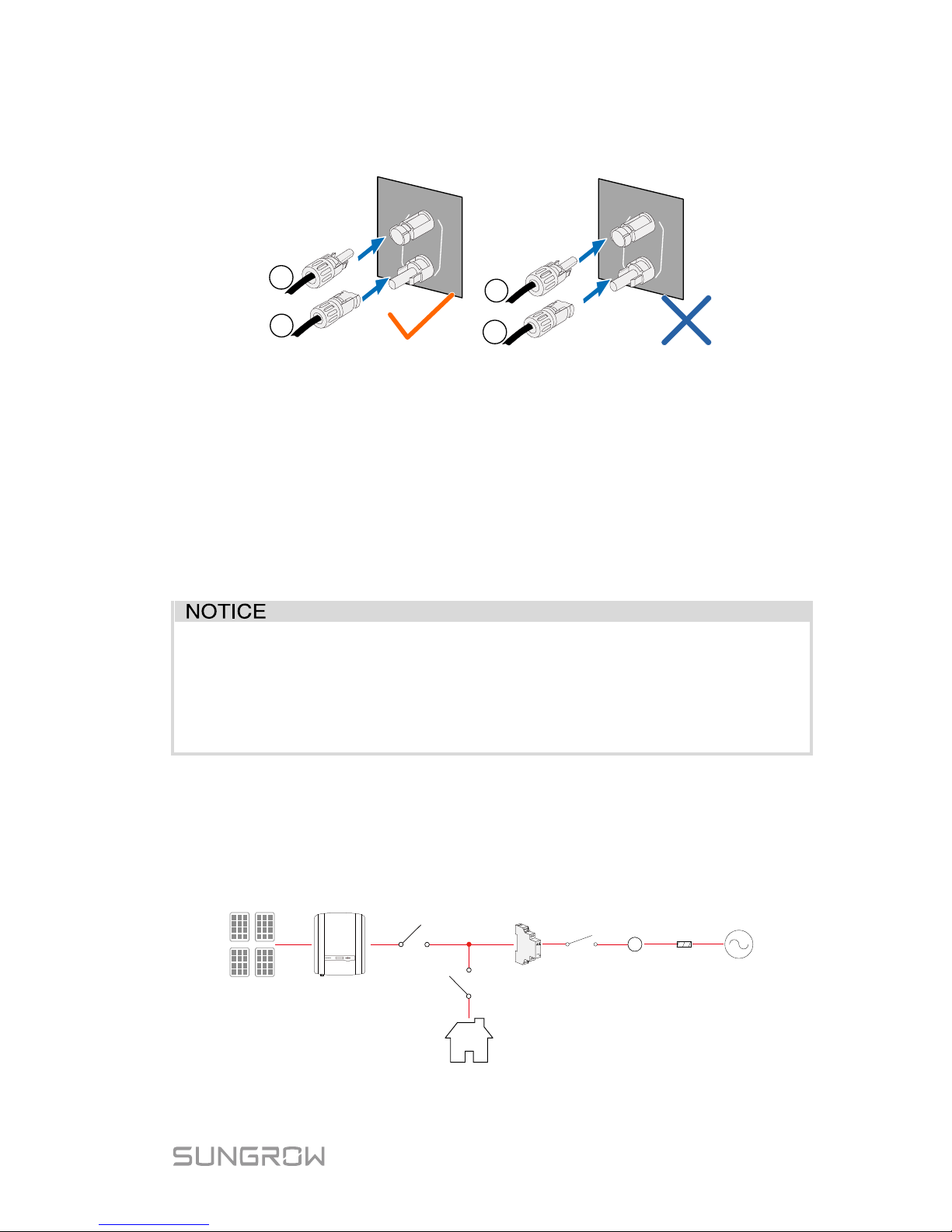
The inverter will not function properly if any PV polarity is reversed.
If the PV connectors are not assembled into place, it may cause an arc
or overheat. The loss caused by thi s issue will void the warranty.
5.4.3 Installing the PV Connector
Connect the inverter to PV strings ac cording to the foll ow ing procedure.
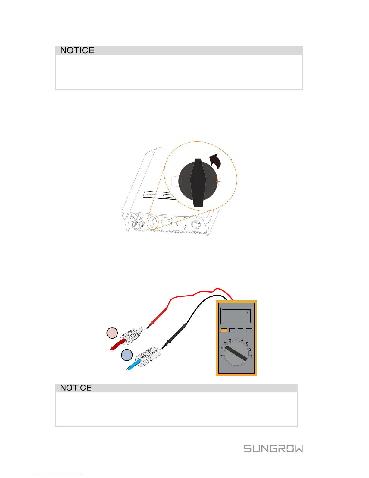
1. (Optional) If you purchase the DC switch, rotate it to “OFF”.
ON
OFF
2. Check the conn ection c able of the PV st ring for t he correct polarity and
that the open-c ircuit voltage does not exceed the invert er input limit of
600 V, even under the lowest operating temperature. Refer to the module
specification supplied by the module manufacturer for detailed
information.
480.0
.
0
The inverter will not function properly if any PV polarity is reversed.
Check the positive and negative polaritiy of the PV strings before
installation.
Page 41
User Manual 5 Electrical Connection
33
3. Plug the positive and the negative PV connectors into corresponding
terminal unt il there is an audible click.
+
-
PV
+
-
-
+
PV
+
PV
-
PV
* The image shown her e is for referenc e only. The act ual product you receive
may differ.
4. (-D series) Seal the unused PV termi nals with the terminal caps.
5.5 RS485 Connection
For the Wi-Fi installation, see the last step in section “4.3 Installing the
Inverter”. More detailed infor mation on the RS485 c ommunic ation modul e can
be found in the r espective manual.
The RS485 terminal can also be used to connect an external RS485
device. For the pin def inition and waterproof procedure, pl ease contact
SUNGROW.
Failure to comply with t he requir ements of wiring or wat erproofing will
void the warran ty.
5.6 Meter Connection
The SUNGROW single-phase energy meter should be installed next to the
main switch.
Sungrow meter
Home Appliance
PV strings
A
Meter
link
Network
meter
Main
switch
Utility
grid
Solar switch
Inverter
Page 42
5 Electrical Connection User Manual
34
5.6.1 On the Meter Side
For Single-phase Energy Meter
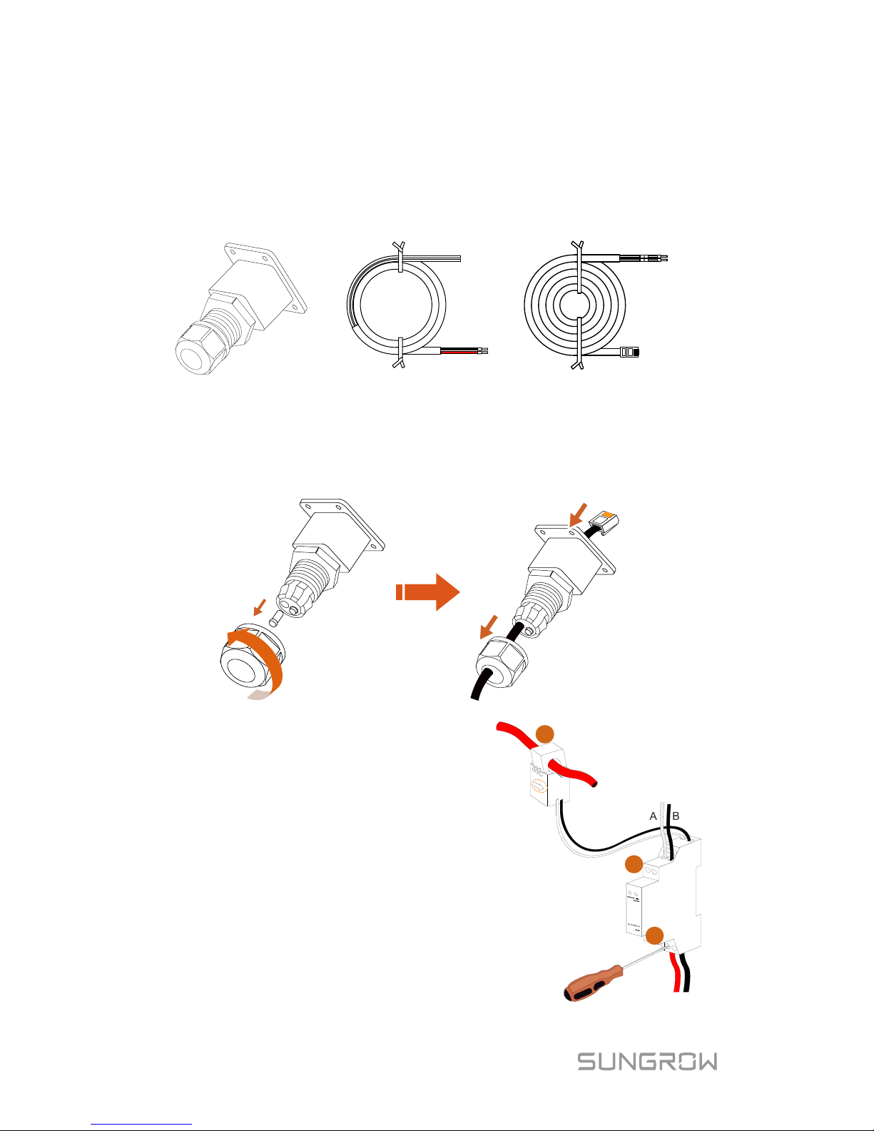
1. Take out the communication connector from inverter’s packaging, and
the meter (w ith 1-phase sensor) and cables from the meter’s packaging.
L
N
B
A
Power supply cable Meter RS485 cable
Communication connector
2. Unscrew t he swivel nut from the cabl e gland and rem ove the wat erpr oof
plug from the left inlet. Lead the A and B plugs from inside out through
the connector. This will result in the cable with the RJ45 plug on the
inside end, and the A and B plugs on the outside.
3. Connect the cables to the meter.
− (a) Tighten the
power supply
wires to terminal 3 (L) and
terminal 6 (N).
−
(b) Tighten the RS485 wires to
terminal 2 and terminal 5.
− (c) Place the 1-phase sensor
around the phase wire (L
) from
the main switch.
The CT clamp of 1-phas e sensor
can be placed b efore or after the
main switch.
N
Grid
Load
L
c
a
b
Page 43
User Manual 5 Electrical Connection
35
Make sure that th e CT clamp of 1-phase sensor is installed in the right
direction: the arrow on the sensor must point away from the grid
towards the lo ad.
For Three-phase Energy Meter
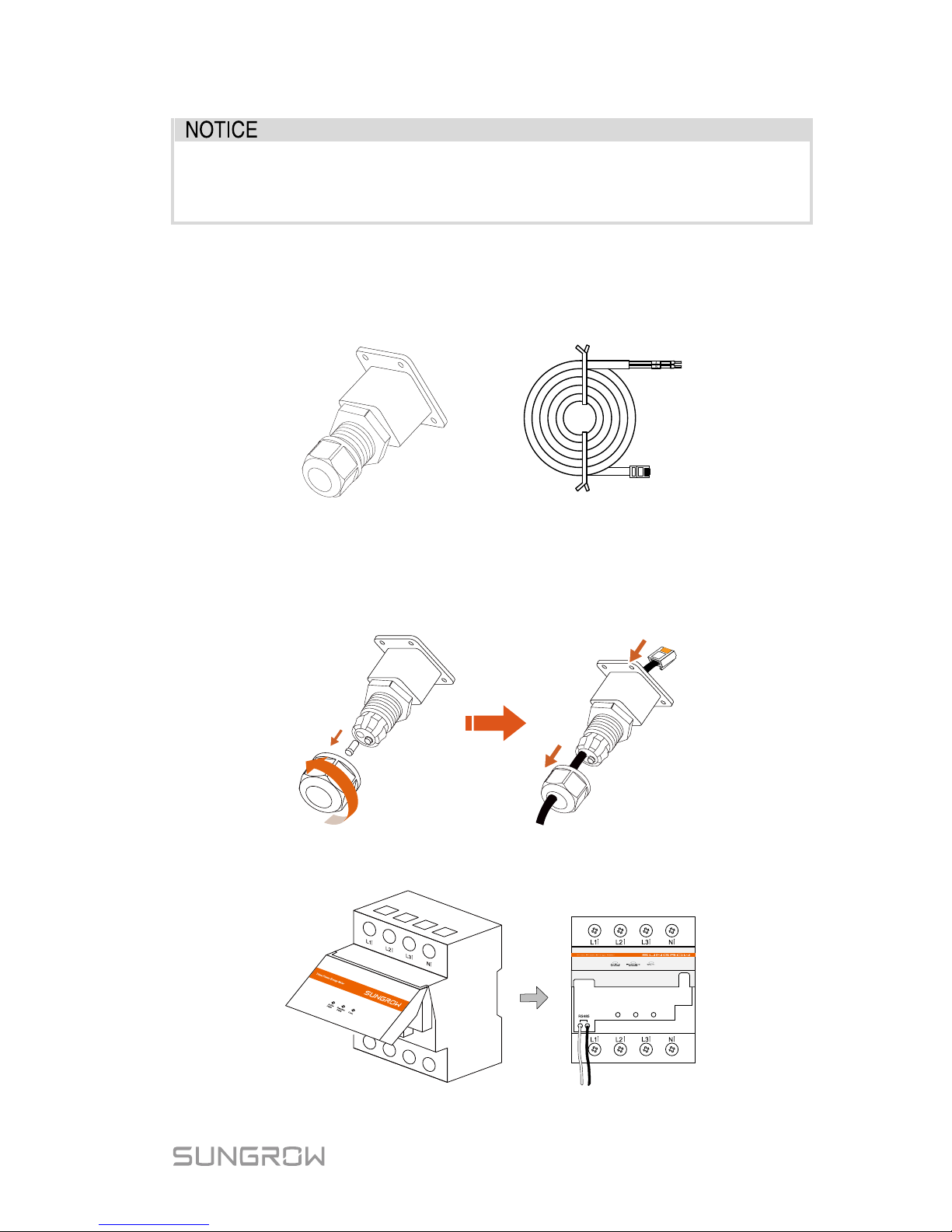
1. Take out the communication connector from inverter’s packaging, and
the meter and RS485 cable from the meter’s packaging.
B
A
Meter RS485 cableCommunication connector
2. Unscrew t he swivel nut from the cabl e gland and rem ove the wat erpr oof
plug from the left inlet. Lead the A and B plugs from inside out through
the communic ation connec tor. This will res ult in the c able with the RJ 45
plug on the inside end, and the A and B plugs on the outside.
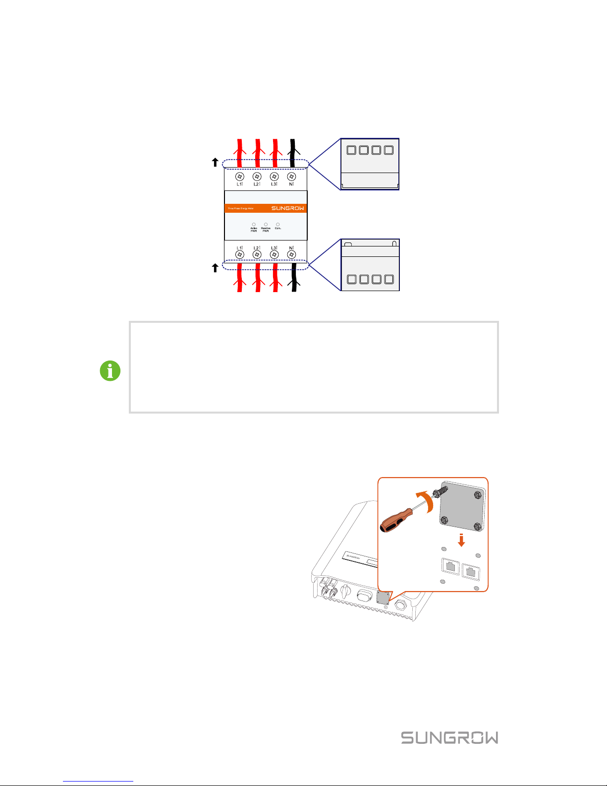
3. Connect the A and B plugs to terminals A and B on the Energy Meter, as
shown below.
AB
Page 44
5 Electrical Connection User Manual
36
4. Strip the insulation from the power wires by 10 mm. Then connect the
wires to the terminals on the Energy Meter, as shown below.
(Cross-section: 10 mm
2
to 25 mm2)
OUT
IN
Load side
Grid side
The line c onduc tor L1 s uppli es power to t he Ener gy Met er. At least
the line conduc tor L1 and the neutral conductor must be connected
to the Energy Meter.
Just connec t the l ine cond uct or L1 and t he ne utral conduc tor, then
the three-phase Energy Meter can be used as a single-phase
meter.
5.6.2 On the Inverter Side
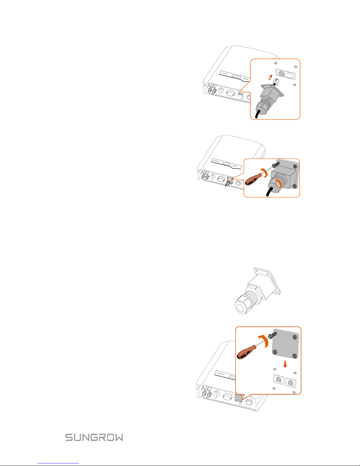
Proceed as follows to connect the RS485 wires to the inver ter.
1. Loosen the screws and
remove the waterproof lid
from the RS485|DRM
terminal.
Note:
Retain the screws for later
installation.
Page 45
User Manual 5 Electrical Connection
37
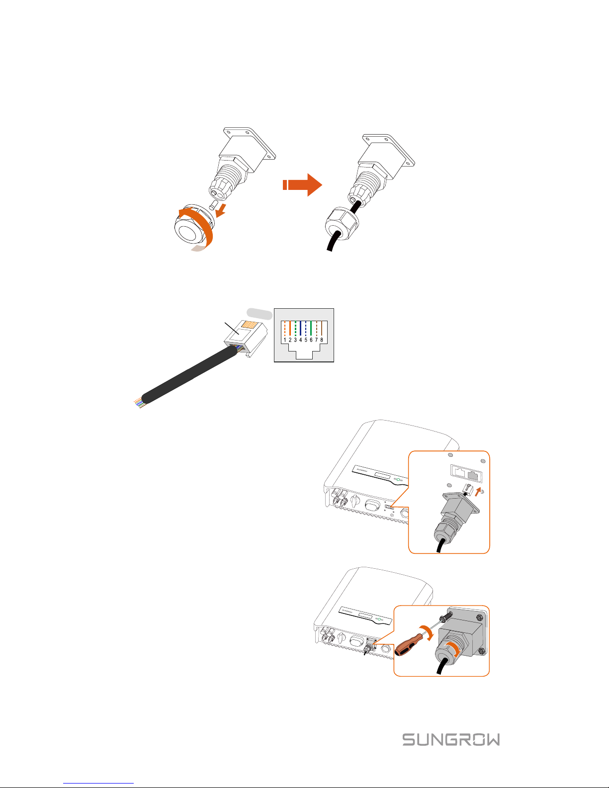
2. Insert the RJ45 plug into the
left (Meter) port until it
makes a clicking sound.
3. If no external demand
response enabling device
connected, secure the
waterproof l id t o the i nver ter
bottom with four screws and
then fasten t he cable gland.
5.7 DRM Connection to an External Device
The cable for connecting to the DRED is not included in the delivery.
Use a TIA/EIA 568B standard network cable with a diameter of 3 mm
–5.3 mm.
1. Take out the communication
connector from the
packaging, as s hown on t he
right.
2. Loosen the screws and
remove the waterproof lid
from the RS485|DRM
terminal.
Note:
Retain the screws for later
installation.
Page 46
5 Electrical Connection User Manual
38
3. Unscrew t he swivel nut from the cabl e gland and rem ove the wat erpr oof
plug from the right inlet. Lead the c abl e thr ough the c abl e gland t hen the
right inlet.
4. Use the Ethernet crimper to crimp the cable and carefully push all 8
unstripped c olored wires into t he RJ45 plug accor ding to TIA/EIA 568B
standard, as shown below.
Corresponding Relationship Between
Cables and Pins
:
Pin 1: White-orange; Pin
2: Orange;
Pin 3:
White-green;
Pin 4: Blue;
Pin
5: White
-blue;
Pin 6:
Green;
Pin 7: White-brown; Pin 8: Brown.
RJ45 Port
RJ45 plug
4
0000;
5. Insert the RJ45 plug into the
right port (DRM)
until it
makes a clicking sound.
6. Secure the water proof lid to
the inverter bot t om wi th f our
screws and then fasten the
cable gland.
7.
Connect the other end to
the external d evice.
Page 47

39
6 Commissioning
Proper commissioning is essential for the system, to protect it against fires,
injury and elec tric shock.
6.1 Inspection before Commissioning
Check the following items before s tarting the inverter:
1. All the installation sites are convenie nt for operation, maintena nce and
service.
2. Check and confirm that the invert er is firmly installed.
3. Space for ventilation is sufficient for one inverter or multiple inverters.
4. Nothing is l eft on the top of the inverter or battery pack.
5. The inverter and accessories are correctly connected.
6. Cables are routed in a safe place or protected against mechanical
damage.
7. The selecti on of the AC circ uit breaker is in ac cordance to this manual
and all applicable local standards.
8. All unused ter m inals at the bottom of the inverter are proper ly sealed.
9. Warning signs and label s are suitably affixed and durable.
6.2 Button Function
Inverter offer s two but tons wit h multipl e functi ons. Pleas e refer to t he followi ng
table before any o peration of the inverter.
Tab. 6-1 Butt on functi on
Button
Operation
Description
ESC
≤1.2 s
Navigate up / down or change the setting values.
Hereinafter referred to as “Touch ESC”.
>1.2 s
Return to a previous menu or cancel the settings.
Hereinafter referred to as “Press ESC”.
ENT
≤1.2 s
Move left or right, or turn pages, or view the active
error/warning from the main screen.
Hereinafter referred to as “Touch ENT”.
>1.2 s
Enter the sub-menu or confirm a selection or settings.
Hereinafter referred to as “Press ENT”.
Page 48
6 Commissioning User Manual
40
6.3 Commissioning Procedure
Make sure all the above mentioned item s meet the requirements.
1. Connect the external AC circuit breaker.
2. Rotate the optional DC switch to “ON”.
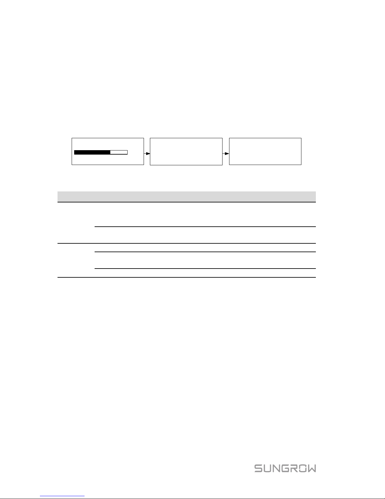
3. If ther e is s ufficient sunl ight, the inverter will enter the runni ng state an d
start to feed A C power to the grid. The LCD screen will be activat ed 5s
later.
Pac:
Status:
3456W
Running
Startup
80%
3456W
Standby
Pac:
Status:
4. Observe the status of the indicator.
Tab. 6-2 Indicator Status Description
Status
Description
Green
Steady on.
The inverter is running norm ally, or with a
warning, or with power limitation.
Inverter status: Running, DRMx.
Flash once every 1s.
The inverter is in the status of standby,
startup or Turn off (via LCD menu).
Red
Steady on.
Inverter faults.
Flash quickly every
0.2s.
Grid faults.
Flash slowly every 1s.
PV faults.
Indicator lights of the communication module are described in the respective
manual.
5. Visit www.isolarcloud.com or iSolarCloud App to view inverter
information. More detailed information on the indicator of the
communicat ion module can be found in the respective Quick Guide.
Page 49
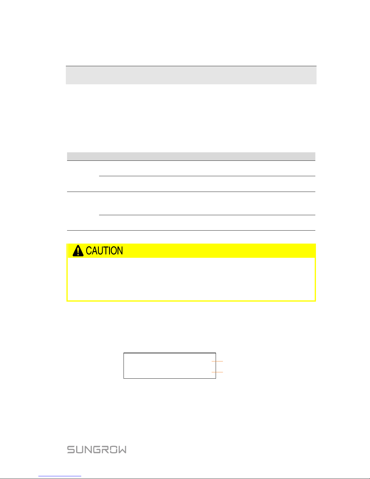
41
7 LCD Operation
7.1 Button Function
The inverter offers two buttons with multiple functions. Please refer to the
following table before any operati on of the inverter.
Tab. 7-1 Butt on functi on
Button
Operation
Description
ESC
≤1.2 s
Navigate up / down or change the setting values.
Hereinafter referred to as “Touch ESC”.
>1.2 s
Return to a previous menu or cancel the settings.
Hereinafter referred to as “Press ESC”.
ENT
≤1.2 s
Move left or right, or turn pages, or view the active
error/warning from the main screen.
Hereinafter referred to as “Touch ENT”.
>1.2 s
Enter the sub-menu or confirm a selection or settings.
Hereinafter referred to as “Press ENT”.
Risk of burns due to hot comp onents!
Do not touch any hot parts (such as heat sink) during operation. Only
the buttons and the optional DC switch can safely be touched at an y
time.
7.2 Main Screen
After successful commissioning, the LCD screen will enter the main screen.
Pac
:
Status:
3456W
Running
Inverter power
Inverter status
If there is no button operation for:
1 minute, LC D backlight will be automatically deacti vated;
2 minutes , system will return to the default menu (mai n screen).
Page 50
7 LCD Operation User Manual
42
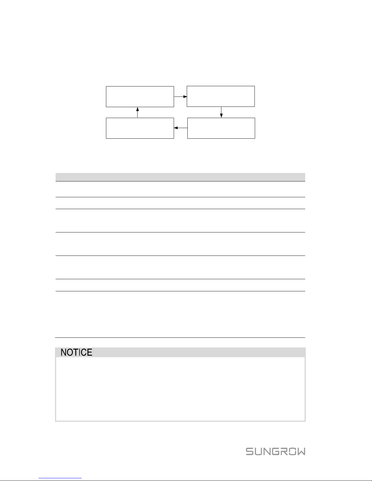
When there is no button operation for more than 8 seconds on the main screen,
the displaye d information wi ll automati cally cycle t hrough to provide addi tional
data: Main screen, energy, PV data, utility grid data. The screen will cycle every
2 seconds. Press any button to quit this mode.
E
-total: 1999kWh
E-today: 20.0kWh
Ipv
: 2.9A
Grid Vtg:
Grid Frq:
221.7V
50.0Hz
Vpv: 250.0V
Pac
:
Status:
3456
W
Running
* The images shown here are for your reference only. For –D series, all PV
input inform ation will be displayed.
Tab. 7-2 Status Description
State
Description
Standby
The inverter waits for sufficient sunlight, then the DC voltage
recovers.
Startup The inverter is initializing and synchronizing with the grid.
Running
After being energized, the inverter tracks the PV strings’
maximum power point (MPP) and feeds the AC power to grid.
This mode is the normal mode.
DRMx
The inverter is connected to an external demand response
enabling devic e and the DRM switch is set to ON via the LCD
menu.
Turn off
The inverter will stop running by manual “OFF” via the LCD
menu or with the DRM0 command from external DRED. Set to
“ON” if you want to restart the inverter.
Upgrading The DSP or LCD firmware is upgrading.
Error xxx
If an error occurs, the inverter will automatically stop operation,
trigger the AC relay and show “Error xxx” on the LCD with the
indicator red (xxx is the error code).
Once the error is cleared in recovery time, the inverter will
automatically try to resume normal operation. The recovery
time can be set via the App.
If the device is in standby mode for more than 10 minutes, please
check:
Whether the i nsolation is sufficient and the PV connection is correct.
If no anomaly is found, di sconnect and reconn ect the DC swi tch and
the main swit ch to restart.
If it still does not wor k, contact SUNGROW.
Page 51
User Manual 7 LCD Operation
43
Viewing the Active Error/Warning
If the status on t he main sc reen is “Error xxx”,
Touch ENT to vi ew the active error code.
If the inverter is running with a warning, Touch
ENT to view the active warning code.
Only one error or warning can be displayed on
this screen. Refer to “8.1 Troubleshooting”
for a solut ion.
Error
010
Warning
514
or
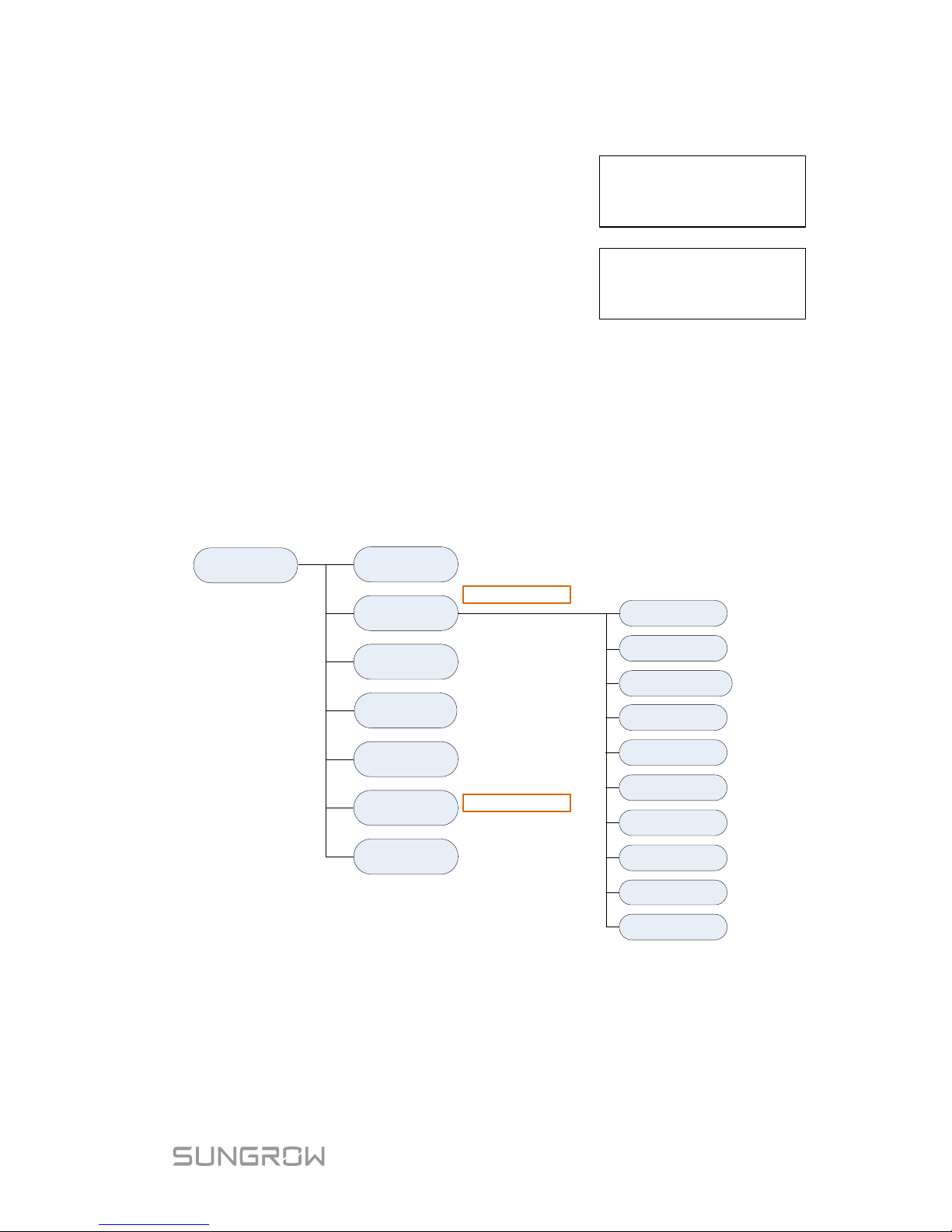
7.3 Menu Structure
For the running i nformatio n, the power valu e indicated r epresents the aver age
value during t he time interval.
The energy yields displayed are indicative only. For the actual yields, please
refer to the energy meter of electric utility company.
Run Info
Settings
Time
Country
Error Record
Grid Prot. Param
Main Menu
Zero-export
Password: 111
Device Info
ON/OFF
Existing Inverter
Password: 111
DRM Switch
Param Reset
Energy Adj.
GND Detect
Comm. Param
Ethernet Config
PF
* Reserved
Fig. 7-1 LCD Menu Tree
Page 52
7 LCD Operation User Manual
44
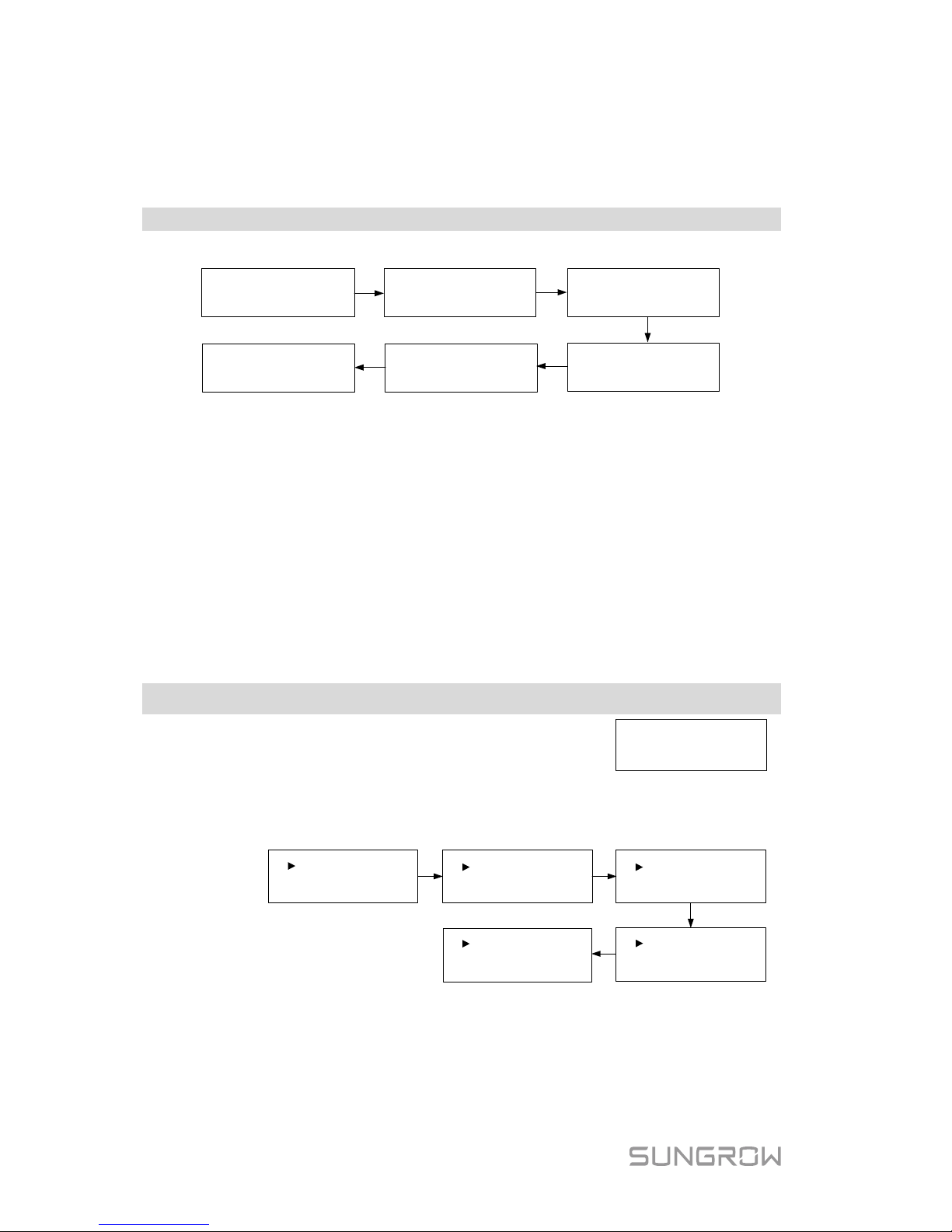
7.4 Viewing Running Info
Proceed as follows to look through the detailed running information.
Main Screen ( P ress ENT)→Menu→Run Info (Press ENT)
Scroll pages by touching ENT / ESC.
E-
total
: 1999
kWh
E
-
today:
20
.
0
kWh
Ipv1
: 2
.
9A
Grid Vtg
:
Grid Frq:
221.
7
V
50
.
0
Hz
Vpv
1:
250
.0
V
Ipv2:
2.
6
A
Vpv2:
244
.
4V
Pac
:
Iac
:
1338.5W
6.0A
Meter Power:
2210W
P
max
Limit:
100%
Meter power:
+ (omitted): The inverter is sourcing power to the grid.
-: The inverter is sinking power from the grid.
P
max
limit: only indicated for the derating in the event of over-temperature,
overvoltage or over-frequency.
7.5 Advanced Settings
7.5.1 Inputting the Password
The parameter s ettings are prot ected with a password. If you want to set t he
inverter’s parameters, you hav e to input the correc t password.
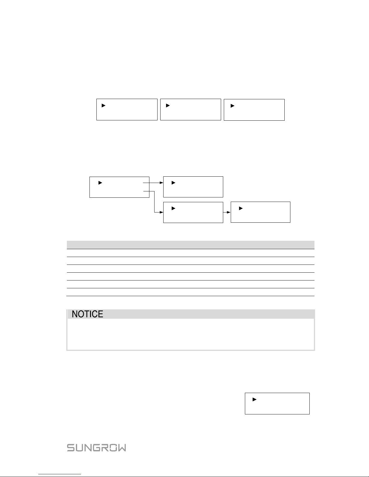
Main Screen (P ress ENT)→Menu (Touch ESC)→Settings ( P ress ENT)
Touch ESC to add the value and
Touch ENT to move the cursor.
Input the password 111.
Password: 1 1 1
Press ENT to confirm the password and enter the submenu.
Touch ESC to navigate down and Press ENT to confirm.
Grid Prot. Param
Param Reset
DRM Switch
Zero-export
PF
Energy Adj.
Ethernet Config
Comm. Param GND Detect
Existing Inverter
7.5.2 Setting Protective Parameters
Protective parameters are designed for the threshold values that can trigger the
protecti ve function of the inver ter. The thr eshold values are compli ant with the
requirements of local safety standar ds and the utility grid.
Page 53
User Manual 7 LCD Operation
45
If the protection func tion is triggered, the inverter wi ll automatical ly disconnect
from the grid with the ”Error xxx” state displayed on t he LCD main sc reen. After
the grid voltage or f requency recovers to the specified range, t he inverter will
start running norm ally and can reconnect t o the grid.
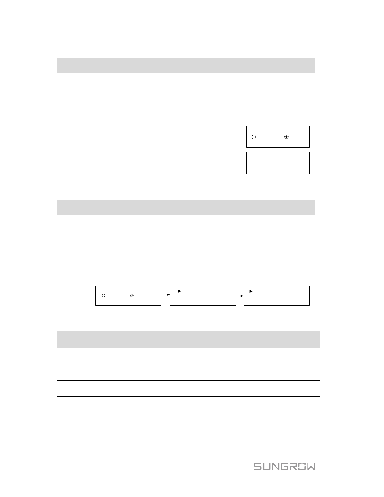
Touch ESC to choose the item and press ENT to enter the setting i nterface.
Volt-watt
Single/Mul Prot.
Prot. Recover
Grid Prot. Adj.10 Min Over Vtg En.
Single/Multiple Protection
Touch ESC to change the value and touch ENT to move the cursor.
Confirm settings by pressing ENT.
Confirm settings and scroll pages by pressing ENT.
2
-Vmax:
265.0V
2-
Vmin: 180
.0V
1-Vmax: 260.0V
1-Vmin: 180.0V
Multi. stage
Single
stage
Vmin:
180.
0
V
Vmax
: 260.
0V
Tab. 7-3 Protective Parameters and the Range
Parameter
Explanation
Range
V
max
Grid over-voltage
230.0 V–277.0 V
V
min
Grid under-voltage
179.0 V–230.0 V
1-V
max
Grid over-voltage 1 (V>)
230.0 V–277.0 V
2-V
max
Grid over-voltage 2 (V>>)
230.0 V–277.0 V
1-V
min
Grid under-voltage 1 (V<)
179.0 V–230.0 V
2-V
min
Grid under–voltage 2 (V<<)
179.0 V–230.0 V
* Refer to Tab. 7-7 for the default values of the parameters.
Too high grid voltage may affect the normal usage and the
life of
household loads. The loss of any or all the warranty rights may follow if
the protection set-point is beyond the specified range.
Protection Recover
Vmax-rec (230.0 V–277.0 V):
Recovery value for over-voltage error. Inverter will start
operating when the grid voltage falls below this value.
Vmin-rec (179.0 V–230.0 V):
Recovery value for under-voltage error. Inverter w ill start
operating when the grid voltage is above this value.
Vmax
-rec: 253.0V
Vmin-rec: 205.0V
Page 54
7 LCD Operation User Manual
46
Tab. 7-4 Default Parameters for Grid Standards
Parameter
Other
(Default)
AG EE EG PN PC WP
V
max-rec
(V)
253.0
253.0
253.0
253.0
253.0
253.0
253.0
V
min-rec
(V)
205.0
205.0
182.0
182.0
205.0
205.0
205.0
10-Minute Over-voltage Protection
ON: enables t he protection fun ction by default. The
inverter will automatically disconnect from the grid
within 3 s when the average voltage for a 10 min
period exceeds the set-point of 10 Min Over Vtg.
OFF: disables the function.
Range: 244.0 V–258.0 V
10
Min Vtg
: 255
.0
V
OFF
ON
The default val ue of 10 Mi n Vtg is 248. 0 V for New Zeala nd (code “NZ”). Refer
to the following table for different gr id standards in Australia.
Parameter
Other
(Default)
AG EE EG PN PC WP
10 Min Vtg
255.0
255.0
255.0
257.0
258.0
255.0
258.0
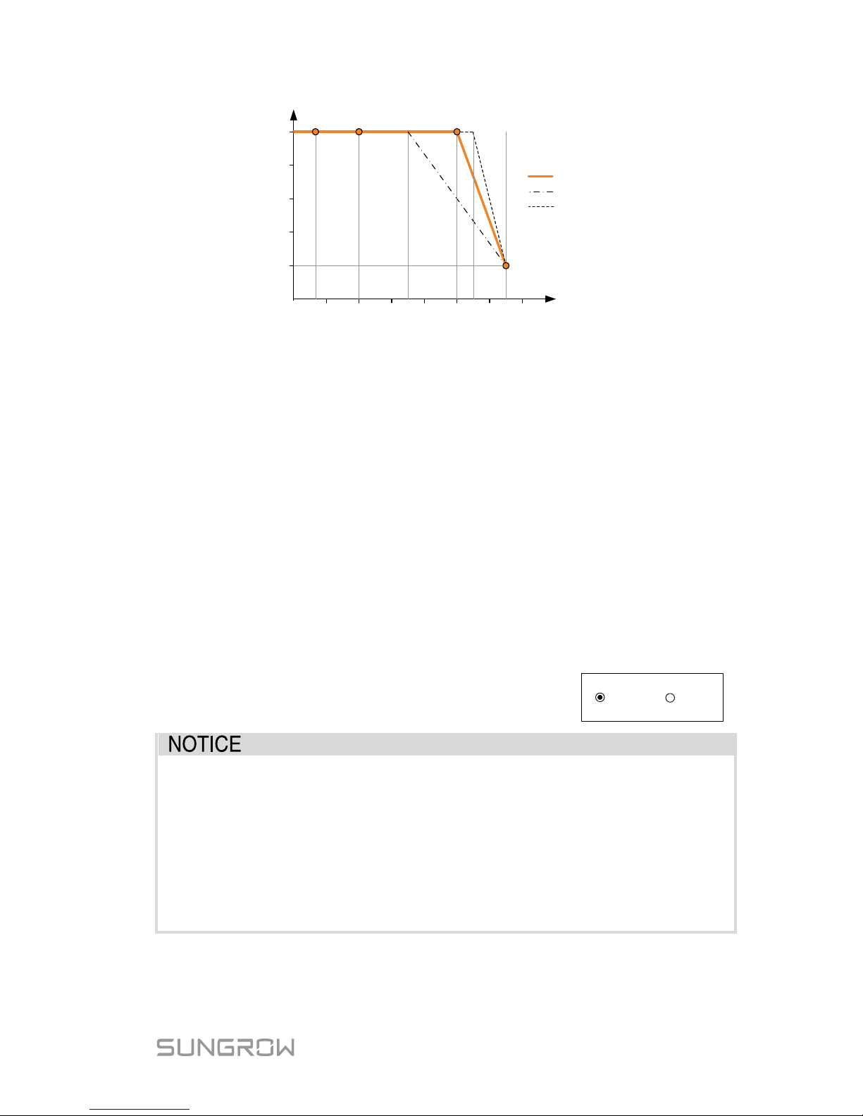
Volt-watt Response
The Volt-watt response mode is enabled by default.
Set four grid voltage reference values. The output power of the inverter will vary
in response to the grid voltages.
OFF ON
V1 Ref.: 207.0V
V2 Ref.: 220.0V
V4 Ref.: 265.0V
V3 Ref.: 250.0V
Tab. 7-5 “Volt-watt” Mode Parameter Explanations
Parameter Explanation
Default
Range
AU
NZ
V1 Ref.
Grid voltage reference
value 1
207.0 V 207.0 V
Not
applicable
V2 Ref.
Grid voltage reference
value 2
220.0 V 220.0 V 216 V–230 V
V3 Ref.
Grid voltage reference
value 3
250.0 V 244.0 V 235 V–255 V
V4 Ref.
Grid voltage reference
value 4
265.0 V 255.0 V 244 V–265 V
The response curve is defined by the voltage reference values and
corresponding power levels.
Page 55
User Manual 7 LCD Operation
47
Power, P/P
rated
%
200
Inverter Voltage, V
V2
V3 V4
210
220
230
240
250
260
270
40%
60%
20%
80%
0%
V1
100%
Default characteristic
Range (lower limit)
Range (upper limit)
Fig. 7-2 Volt-watt Response Curve (“AU” for example)
Grid Protection Voltage Adjusting
All Sungrow’s inverters are compliant with the standard AS/NZS 4777 related to
grid protection requirements. In order to work with unstable utility grids,
inverters are equipped with automatic protection voltage adjusting function
(disabled by default). This mode can be enabled via the LCD.
OFF (default setting): the function is disabled. The grid protection voltage
cannot automatically adjust.
ON: enables t he protection func tion. The inverter wi ll automatically adjus t the
protection threshold to a higher value so as to be normally connected to the grid
in the event of gr i d ov er-voltage. The V
max-rec
will be ad jus ted t he sam e wit h t he
V
max
, with an upper limit value not higher than V
max
.
If the setting is changed from ON to OFF, you should
set the protection voltage as specified in Tab. 7-3
according to local protection requirements.
OFF ON
If the automatic prot ection voltage adjusting function i s set to ON, t he
volt-watt response and the 10-m inute over-voltage protection f unction
will be automatically disabled.
If the line voltage or frequency goes outside pre-determined
parameters, the inverter must shut down for safety purposes, which
means it is not a f aulty inverter in t hese instances. High line voltages
may damage home appliances and Sungr ow is not held r esponsible or
liable for these issues.
Page 56
7 LCD Operation User Manual
48
7.5.3 Zero-export Setting
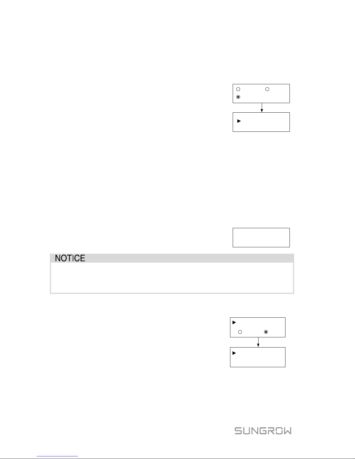
Touch ENT / ESC to select and press ENT to confirm.
Touch ESC to change the value and touch ENT to move the cursor. Press
ENT to confirm the export power per centage.
OFF: all the power w ill be expor ted to the grid. (by
default)
ON: no power will be exported to the grid.
Partial: part of t he export power will be expor ted to
the grid.
Total Export: the ex por t power upper limit of the whole
system.
ON
OFF
Total Export
: 1000W
Partial
(0W–5000
W)
The range of export power will automatically change:
When the exis ting inverter is disabled: 0 to (rated pow er of the inverter)
When the existing inverter is enabled:
The lower limit is the rated power of existing inverter.
The upper limi t is ([rated power of the exist ing inverter] + rat ed power of
the inverter ).
For example, retrofit an existing PV system (rated power: 2000 W) with SG5K-D
(rated power: 5000 W). The total export range will be 2000 W – 7000 W.
A prompt will appear when you s et it for the s econd
time.
Set by solar
professionals only!
With the password 111, the zero-export setting can only be done at the
first time. The later modification can be performed by professionals only,
please contact SUNGRO W.
7.5.4 Adding the Existing Inverter
Rated-P: rat ed pow er of the existi ng inverter.
This function is OFF by default.
If the existing
inverter is s et to ON, its rated power is the lower
limit for export power setting.
ON
OFF
Rated-P:
Existing Inverter
(
0W~30000W)
2000
W
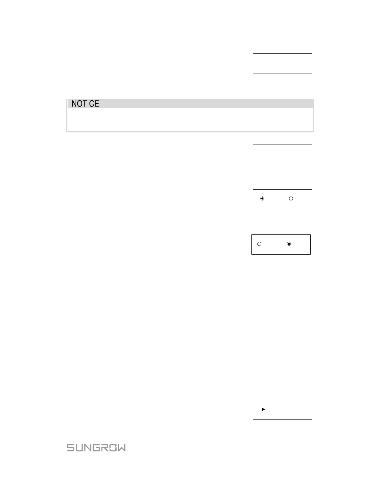
7.5.5 PF Setting
The inverter is capable of operating with fi xed power factor. The PF ranges from 0.8
leading (+) to 0.8 lagging (-).
Page 57
User Manual 7 LCD Operation
49
+ (Leading): the inverter is sourcing reactive power to
the grid.
- (Lagging): the inverter is sinking reactive power from
the grid.
PF
:
+
1
.
000
7.5.6 Parameter Reset
All settable
parameters will return to the default values once the
“Param Reset” operation is performed.
Press ENT to confirm the operation.
Press ESC to discard the operation.
Confirm resume
setting?
7.5.7 DRM Switch Setting
Touch ENT / ESC to select and press ENT to confirm.
ON: enable the DRM function.
OFF: disable the DRM function. (By default)
OFF ON
7.5.8 GND Detection
Touch ENT / ESC to select and press ENT to confirm.
Select ON to enable the GND Detection.
If the
enclosure of the inverter is not grounded, the error
code 106 will be shown on the main screen. The
buzzer inside will sound at the same time.
OFF
ON
7.5.9 Energy A djus tment
If the accumul ative val ue “E-total” displayed on invert er scr een is different fr om
the value indicated on the metering device, you should adjust the energy
deviation.
(Energy Adj. value) = (Real m easured value) - (E-total reading value)
Touch ESC to add the value and Touch ENT t o m o ve
the cursor. Press ENT to confirm the setting.
The “+” can be changed to “-” by touching ESC.
The adjustment rangs from -9999 kWh to +9999 kWh.
+0000 kWh
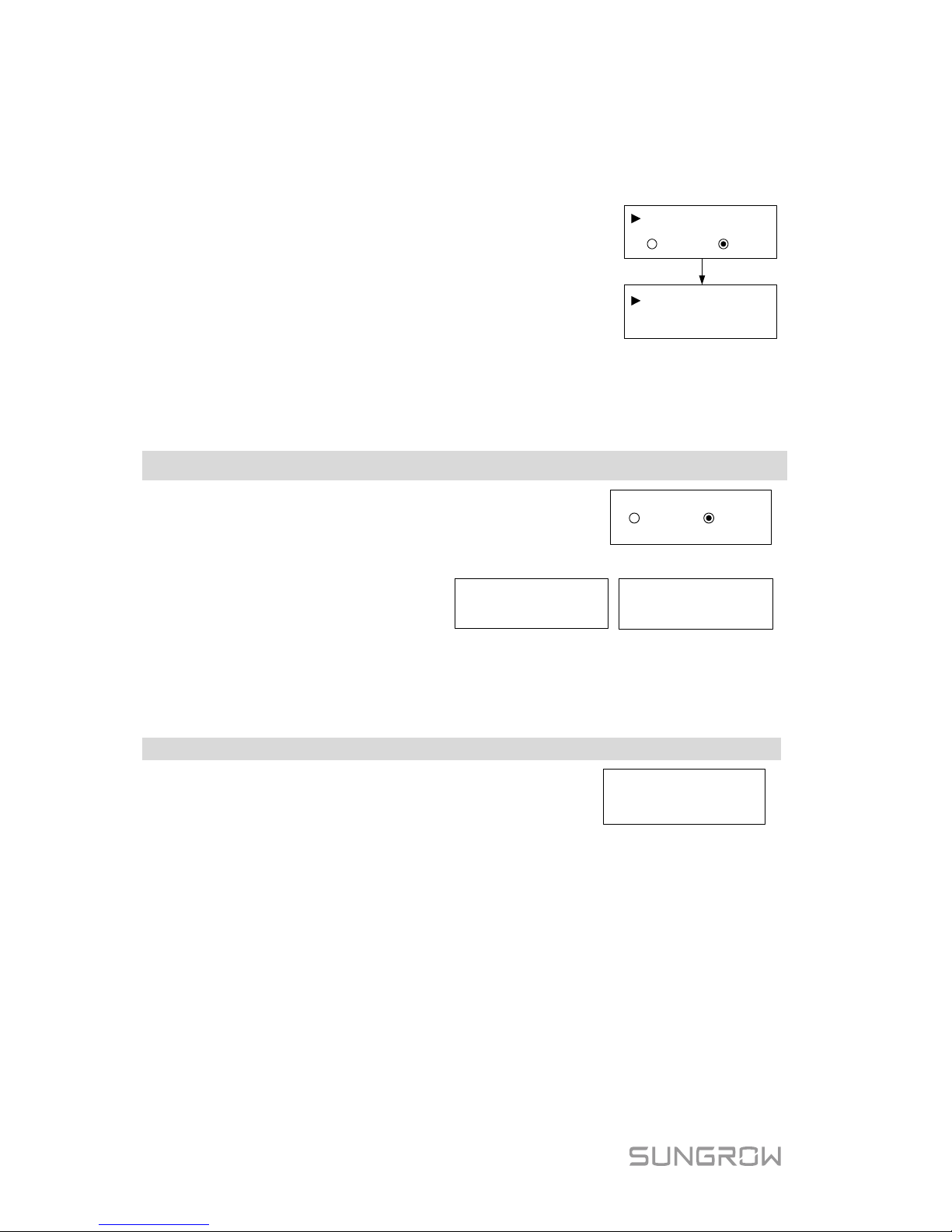
7.5.10 Setting Communication Parameter
Touch ESC to set the appropriate value and
touch ENT to move the cursor. Confirm settings
by pressing ENT.
Device address range: 1-247.
Modbus ID
: 031
Page 58
7 LCD Operation User Manual
50
7.5.11 Ethernet Configu ra tion
The Ethernet setting is reserved for later usage.
Touch ENT to select and press ENT to confirm.
OFF: The IP address should be assigned manually.
ON: Automatically assign IP address from the home
router.
Touch ESC to switch between the DHCP and the IP
interfaces.
ONOFF
IP:
DHCP:
192.
168.001
.100
7.6 Starting/Stopping the Inverter
Main Screen (Press ENT)→Menu (Touch ESC)→ON/OFF (Press ENT)
Touch ENT / ESC to select and press ENT to
confirm.
ON OFF
Confirm your selection by pressing ENT.
Confirm turn on? Confirm turn off?
7.7 Viewing the Error Record
Main Screen (Press ENT)→Menu (Touch ESC)→Error Record (Press ENT)
Scroll pages by touching ENT / ESC.
3 records can be displayed on each page and 20
records at most for all.
Press ESC to exit.
2 15/01
/21 09:10:08 004
1 15/01/21 09:10:12 010
3 15/01/21 09:11:08 005
P1/7
7.8 Setting the Time
The correct system time is very important. If there is deviation between the
system time and t he l ocal t ime, the inver t er w il l not operat e nor m all y. The clock
is in 24-hour format.
Page 59
User Manual 7 LCD Operation
51
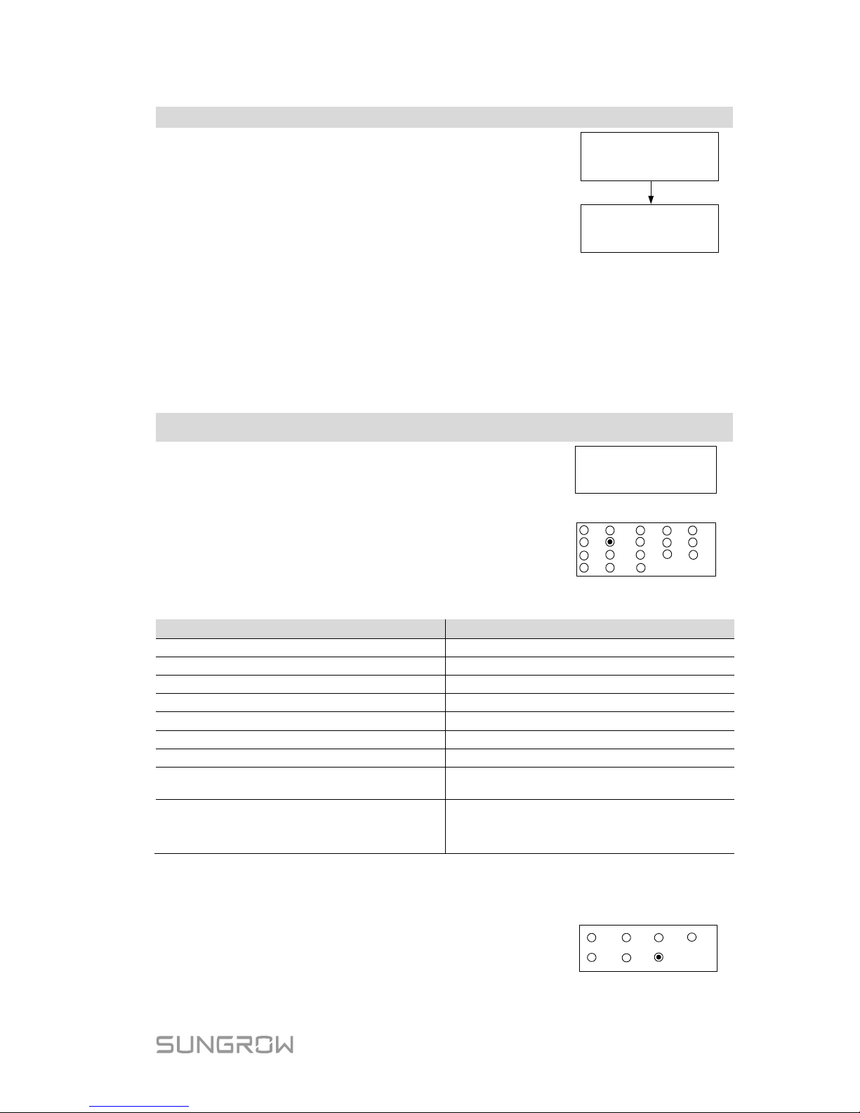
Main Screen (Press ENT)→Menu (Touch ESC)→Time (Press ENT)
DD, MM, and YY stand for day, month, and year
respectively.
hh, mm, and ss stan
d for hour, minute, and
second respectively.
Scroll pages by pressing ENT.
Date: 05 / 01 / 17
Time: 10 : 30 : 05
DD / MM / YY
hh : mm : ss
7.9 Setting the Country
To mak e t he prot ec tion paramet er s set t ing conveni ent , inver ter provi des bui l t -in
protection parameters for certain countries. The country setting is protected
with a password.
Main Screen (P ress ENT)→Menu (Touch ESC)→Country (Press ENT)
Touch ESC to add the value and Touch ENT to m ov e
the cursor. Input the password 111.
Password: 1 1 1
Touch ENT / ESC to choose the country and press
ENT to confirm.
If the country selected is not in t he list, please choose
Other and then set the protection parameters manually.
GB
DE
FR
ES
BE
NL
AT
AU
CN
CZ
SE
KR
TH
LUX
Other
NZ
BRA
IT
Tab. 7-6 Country Code Description
Code
Full Name
Language
Code
Full Name
Language
GB
Great Britain
English
BRA
Brazil
Portuguese
DE
Germany
German
CN
China
Chinese
FR
France
French
SE
Sweden
English
IT
Italy
Italian
TH
Thailand
English
ES
Spain
English
KR
Korea
English
AT
Austria
German
LUX
Luxemburg
German
AU
Australia
English
NZ
New Zealand
English
CZ Czech English NL Netherlands English
BE Belgium English Other
Country not
included
above
English
* The countr y code “Other” repr esents 50 Hz grid and 6 0 Hz gri d. The inver ter
will automatically choose 50 Hz or 60 H z according to the local grid frequency.
If the country code is set to “AU”, the grid company
setting will appear. Touch ENT / ESC to choose the
grid standard and press ENT to confirm.
EE
AG
PN
PC
WP
EG
Other
Page 60
7 LCD Operation User Manual
52
When the grid is set to “ EE” or “EG”, t he r eacti ve power regul at ion wi ll be i n PF
mode with the pow er factor of +0.90 (0.90 lagging).
Tab. 7-7 Grid Standard Description
Grid company Code
Company
AG
AusGrid , NSW
EE
Ergon Energy, QLD
PN
SA Power Networks,SA
PC
Powercor,VIC
WP
Western Power,WA
EG
Energex, QLD
Other
Company not mentioned above
Each grid standard c ode represents cor responding protecti ve parameters that
have been preset before deli very. The parameters for “Other” are applicable t o
Australi an and compliant with the standard AS/NZS 4777.
The values listed in the following table are for your reference only. Please follow
the requirements of local grid standard.
Tab. 7-8 Protective Parameters of Grid Standards
Parameter
Other
(Default)
AG EE EG PN PC WP
Over-voltage
1-V
max
(V)
260.0
260.0
260.0
260.0
260.0
260.0
260.0
1-Time (s)
2.0
2.0
2.0
2.0
2.0
2.0
2.0
2-V
max
(V)
265.0
265.0
265.0
265.0
265.0
265.0
265.0
2-Time (s)
0.20
0.20
0.20
0.20
0.20
0.20
0.20
Under-voltage
1-V
min
(V)
180.0
200.0
180.0
180.0
180.0
180.0
180.0
1-Time (s)
2.0
2.0
2.0
2.0
2.0
2.0
2.0
2-V
min
(V)
180.0
200.0
180.0
180.0
180.0
180.0
180.0
2-Time (s)
2.0
2.0
2.0
2.0
2.0
2.0
2.0
Over-frequency
1-F
max
(Hz)
52.00
52.00
52.00
52.00
52.00
52.00
51.50
1-Time (s)
0.20
0.20
0.20
0.20
0.20
0.20
0.20
2-F
max
(Hz)
52.00
52.00
52.00
52.00
52.00
52.00
51.50
2-Time (s)
0.20
0.20
0.20
0.20
0.20
0.20
0.20
Under-frequency
1-F
min
(Hz)
47.00
48.00
47.00
47.00
47.00
47.00
47.00
1-Time (s)
1.50
1.50
1.50
1.50
1.50
1.50
1.50
2-F
min
(Hz)
47.00
48.00
47.00
47.00
47.00
47.00
47.00
2-Time (s)
1.50
1.50
1.50
1.50
1.50
1.50
1.50
10-min voltage
1-V
10-min
(V)
255.0
255.0
255.0
257.0
258.0
255.0
258.0
Page 61
User Manual 7 LCD Operation
53
Refer to Tab. 7-3
for the parameter explanation and range. If you
(qualified personnel only) need to modify the voltage protective
parameters, please refer to “Single/Multiple Protection”.
7.10 Viewing Device Info
Main Screen (Press ENT)→Menu (Touch ESC)→Device Info (Press ENT)
These interfaces show the read-only information.
Scroll pages by touching ENT / ESC.
Press ESC to exit.
SG3K-S
Device Type:
SN:
A1610090001
Country:
AU
Version
:
CrysG2-V31_FW_V22
Page 62

54
8 Troubleshooting and
Maintenance
8.1 Troubleshooting
8.1.1 LED Indicator
See “Tab. 6-2 Indicator Status Description” for the defi nition.
Fault Type
Troubleshooting
LED indicator
cannot be lit.
1. Disconnect the AC circuit breaker.
2. Rotate the optional DC switch to “OFF”.
3. Check the polarity of DC input.
Green indicator
goes out.
1. Disconnect the AC circuit breaker.
2. Rotate the optional DC switch to “OFF”.
3. Check the inverter electrical connection. Refer to “5
Electrical Connection”.
4. Check whether the voltage of DC input exceeds the
inverter start-up voltage.
5. If all the above conditions are OK, please contact
SUNGROW.
8.1.2 Errors on the App or LCD Screen
If an error occurs, the “Error” state will be show n on the main s creen. We need
the following information to provide you with the best assistance:
inverter type (e.g. string, central, grid-connected, hybrid, transformerless,
single phase, triple phase, si ngle MP PT, multiple MPPTs),
product name,
serial number of the inverter,
error code / name, and
a brief description of the problem.
Page 63
User Manual 8 Troubleshooting and Maintenance
55
Code
Description
Troubleshooting
002
Grid over-voltage.
The grid voltage
exceeds the protective
value. (stage I)
1. Check the voltage of the grid.
2. If the grid voltage exceeds the
permissible range of inverter protection
parameters, ask utility grid company for
solution.
3. If the grid voltage is within the
permissible range, contact Sungrow Service
Dept.
003
Transient over-voltage.
The g
rid transient
voltage exceeds
inverter allowable
upper limit.
1. This is a short-term fault due to grid
condition. Wait a
moment for inverter
recovery.
2. If the fault persist
s, please contact
Sungrow Service Dept.
004
Grid under-voltage.
The grid voltage is
below
the protective
value. (stage I)
1. Check the grid voltage.
2. If the grid voltage exceeds the
permissible range
of inverter protection
parameters, ask utility grid company for
solution.
3. If the grid voltage is within the
permissible range, contact Sungrow Service
Dept.
005
Grid under-voltage.
The grid voltage is
below
the protective
value, which is lower
than the protective
value of error 004.
(stage II)
1. This is a short-term fault due to grid
condition. Wait a moment for inverter
recovery.
2. If the fault persist
s, please contact
Sungrow Service Dept.
006
AC over-current.
The AC output current
exceeds inverter
allowable upper limit.
1. The inverter will resume if the output
current falls below the protection value.
2. If the fault persists, please contact
Sungrow Service Dept.
007
Transient AC
overcurrent.
1. The inverter will self-recover after several
seconds.
2. If the fault persists, please contact
Sungrow Service Dept.
008
Grid over-frequency.
The grid frequency
exceeds the protective
value. (stage I)
1. Check the grid frequency.
2. If the grid frequency exceeds the
permissible range of inverter protection
parameters, ask utility grid company for
solution.
3. If the grid frequency is within the
permissible range, contact Sungrow Service
Dept.
009
Grid under-frequency.
The grid frequency is
below
the protective
value. (stage I)
Page 64
8 Troubleshooting and Maintenance User Manual
56
Code
Description
Troubleshooting
010 Grid failure (Islanding)
1. Check whether AC circuit breaker is
triggered.
2. Check whether AC cables are all firmly
connected.
3. Check whether grid is not in service.
4. If all conditions are OK and this fault still
occurs in the LCD screen, contact Sungrow
Service Dept.
011
DC injection
over-current.
The DC current
injection of AC current
exceeds the upper
limit.
1. Wait a moment for inverter recovery.
2. If the fault occurs repeatedly, contact
Sungrow Service Dept.
012
Leakage current
over-current.
The leakage current
exceeds inverter
allowable upper limit.
1. Check the PV strings for ground fault.
2. If the fault occurs repeatedly, contact
Sungrow Service Dept.
014
10-
minute grid
over-voltage.
The average grid
voltage in
10 minutes
exceeds the
permissible range.
1. Check whether the inverter selected
country code is the country you are in.
2. Wait a moment for inverter recovery.
3. Check the voltage of the grid. If the grid
voltage exceeds the permissible range of
inverter protection parameters, ask utility
grid company for solution.
4. If the fault occurs repeatedly, contact
Sungrow Service Dept.
015
Grid over-voltage
The grid voltage
exceeds the protective
value, which is higher
than the protective
value of error 002.
(stage II)
1. Check the model of the AC cables.
2. Wait a moment for inverter recovery.
3. If the grid voltage exceeds the
permissible range, ask utility grid company
for solution.
4. If the fault occurs repeatedly, contact
Sungrow Service Dept.
016
The bus voltage or
power is high.
1. Wait a moment for inverter recovery.
2. If the fault occurs repeatedly, contact
Sungrow Service Dept.
019
Bus transient
over-voltage.
The transient bus
voltage exceeds
inverter allowable
upper limit.
1. Wait a moment for inverter recovery.
2. If the fault occurs repeatedly, contact
Sungrow Service Dept.
020
Bus over-voltage.
The bus voltage
exceeds inverter
allowable upper limit.
1. Wait a moment for inverter recovery.
2. If the fault occurs repeatedly, contact
Sungrow Service Dept.
Page 65
User Manual 8 Troubleshooting and Maintenance
57
Code
Description
Troubleshooting
021 PV1 input over-current.
Check the layout and the wiring of PV1
input.
022 PV2 input over-current.
Check the layout and the wiring of PV2
input.
028
PV1 reverse
connection.
Check the cable connections of PV1.
029
PV2 reverse
connection.
Check the cable connect i ons of PV2.
036
The temperature of
radiator is too high.
1. Check whether the ambient temperature
shown on the screen is too high. Wait a
moment for inverter recovery.
2. Check whether there is enough space for
convection.
3. Check whether the inverter is in direct
sunlight.
4. Check whether the fan is normal.
Replace it if necessary.
5. Clean the air inlets.
6. If the fault persists, please contact
Sungrow.
037
The internal
temperature of inverter
is too high.
038
Relay fault on the grid
side.
1. Wait a moment for inverter recovery.
2. If the fault occurs repeatedly, contact
Sungrow Service Dept.
039
The insulation
resistance
of PV to
earth is low. (ISO-flt)
1. Check whether there is a reliable inverter
grounding line.
2. Check whether one of the P V strings is
short-circuited with ground.
3. Wait a moment for inverter recovery.
4. If the fault occurs repeatedly, contact
Sungrow Service Dept.
041
Leakage current
sampling fault.
1. Wait a moment for inverter recovery.
2. If the fault occurs repeatedly, contact
Sungrow Service Dept.
043
Inner
under-temperature
fault.
The ambient
temperature inside the
inverter is too low.
The inverter will recover once the ambient
temperature rises above -25℃.
044
Inverter self-test fault.
1. Wait a moment for inverter recovery.
2. If the fault occurs repeatedly, contact
Sungrow Service Dept.
045
PV1 boost circuit
fault.
046
PV2 boost circuit
fault.
048
Phase current
sampling fault.
Page 66
8 Troubleshooting and Maintenance User Manual
58
Code
Description
Troubleshooting
053
The slave DS P detects
that the
grid voltage
exceeds inverter
allowable upper limit.
1. Check the grid voltage.
2. If the grid voltage exceeds the
permissible range of inverter protection
parameters, ask utility grid company for
solution.
3. If the grid voltage is within the
permissible range, contact Sungrow Service
Dept.
054
The slave DS P detects
that the grid frequency
exceeds inverter
allowable upper limit.
1. Check the grid frequency.
2. If the grid frequency exceeds the
permissible range of inverter protection
parameters,
ask utility grid company for
solution.
3. If the grid frequency is within the
permissible range, contact Sungrow Service
Dept.
056
The slave DS P detects
that the leakage
current exceeds
inverter allowable
upper limit.
1. Check whether there is a grounded fault
of the PV string.
2. If the fault occurs repeatedly, contact
Sungrow Service Dept.
059
Communication alarm
between master DSP
and slave DSP.
1. Wait 1 minute for inverter recovery.
2. If the fault persists, contact Sungrow
Service Dept.
061
Alarm for no inverter
type setting.
Contact Sungrow Service Dept.
070 Fans are defective
Stop the inverter and disconnect the AC &
DC cables. Check whether the fan duct has
been blocked. If not, replace fans.
084
Warning for reverse
cable connecti on of the
Sungrow Meter.
1. Check whether the power cable
connections are correct.
2. If “Existing Inverter” is set to “ON” via
LCD menu, check and ensure that its rated
power is correctly set.
3. For Sungrow single-phase meter, check
whether the CT clamp of the 1-phase
sensor is correctly placed. Refer to “5.6.1
On the Meter Side”.
085
Mismatched software
version.
Please contact Sungrow Service Dept.
100
The AC output current
exceeds the upper
limit.
1. The inverter will resume if the output
current falls below the protection value.
2. If the fault
persists, please contact
Sungrow Service Dept.
Page 67

User Manual 8 Troubleshooting and Maintenance
59
Code
Description
Troubleshooting
101
Grid over-frequency.
The grid frequency
exceeds the protective
value, which is higher
than the protective
value of error 008.
(stage II)
1. Check the grid frequency.
2. If the grid frequency exceeds the
p
ermissible range of inverter protection
parameters, ask utility grid company for
solution.
3. If the grid frequency is within the
permissible range, contact Sungrow Service
Dept.
102
Grid under-frequency.
The grid frequency is
below
the protective
value,
which is lower
than the protective
value of error 009.
(stage II)
106
Abnormal grounding.
Neither the PE terminal
on the AC connection
block nor the second
PE terminal on the
enclosure is reliably
connected.
Check whether there is a reliable inverter
grounding line, if there is access to the
ground, and the fault persists, please
contact Sungrow Service Dept.
200
Bus hardware
over-voltage fault.
The bus voltage
exceeds the protective
value.
1. Wait for inverter recovery after bus
voltage lower.
2. If the fault occurs repeatedly, contact
Sungrow Service Dept.
201
The bus voltage is too
low.
1. Wait a moment for inverter recovery.
2. If the fault occurs repeatedly, contact
Sungrow Service Dept.
202
PV hardware
over-current fault.
The PV1 or PV2
current exceeds the
protective value.
If the fault occurs repeatedly, contact
Sungrow Service Dept.
203
The PV input voltage
exceeds the bus
voltage.
Check the functionality of the PV
connection terminals.
306
Input and output power
mismatching fault.
If the fault occurs repeatedly, contact
Sungrow Service Dept.
315
PV1 current sampling
fault.
Channel sampling anomaly.
Contact Sungrow Service Dept.
316
PV2 current sampling
fault.
320
Leakage current
sensor fault.
Contact Sungrow Service Dept.
409
All temperature
sensors fail.
If the fault occurs repeatedly, contact
Sungrow Service Dept.
Page 68
8 Troubleshooting and Maintenance User Manual
60
Code
Description
Troubleshooting
503
Ambient temperature
sensor
open circuit
warning.
504
Ambient temperature
sensor
short circuit
warning.
505
Radiator temperature
sensor
open circuit
warning.
506
Radiator temperature
sensor
short circuit
warning.
501
External memory
reading/writing
warning.
1. Inverter can normally be connected to the
grid.
2. Power on the inverter again. If the fault
persists, cont act Sungrow Servic e Dept.
514
Abnormal
communication
warning of the
Sungrow Meter.
(Inverter can be
normally
connected to
the grid.)
1. Check whether the power cable
connections of the meter are correct.
2. Check whether the RS485 connection is
correct.
8.2 Routine Maintenance
Risk of inverter damage or personal injury due to incorrect service!
Always keep i n mind that t he inverter is powered b y dual sources: PV
strings and utility grid.
Before any ser vice work, observe t h e following procedure.
Disconnect the AC circuit breaker and then set the DC load-break
switch if the inverter to OFF;
Wait at least 10 minut es for inner capacitors to discharge completely;
Verify that there is no voltage or current before pulling any connector.
Page 69
User Manual 8 Troubleshooting and Maintenance
61
Keep non-related persons away!
A temporary warning sign or barrier must be posted to keep
non-related perso ns away while performing electrical connecti on and
service work.
Risk of inverter damage if it is improperly serviced.
Use accessories and spare parts approved by the inverter
manufacturer only. Never modify the inverter or other components of
the inverter.
Unauthoriz ed alterations will void g uarantee and warrant y claims and
in most cases term inate the operat ing license. SUNGROW shal l not be
held liable f o r any damage caused by such changes.
Any malfuncti on that ma y impair the inver ter saf ety operati on must be
repaired immediately before the inverter is restarted.
Inverter contains no customer servicea ble parts inside. Ple ase contact
local authorized personnel if an y service work is required.
Servicing of the device in ac cordance with t he manual should n ever
be undertaken in t he absenc e of proper tools, test equipm ents or t he
more recent revision of the manual which has been clearly and
thoroughly understood.
Items
Methods
Period
System
clean
Check the temperature and dust of the
inverter. Clean the inverter enclosure.
Check the humidity and dust of the
environment. Meanwhile check whether
the filter function of the air inlet is ok.
Six months to a year (it
depends on the dust
contents in air.)
Page 70
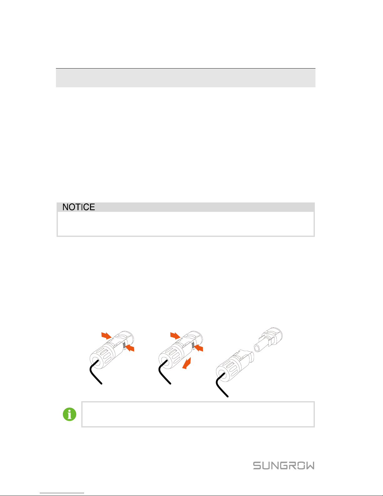
62
9 S yst em Decommission ing
9.1 Disconnecting the Invert er
For maintenance or other service work, the inverter must be switched off.
Proceed as follows to disconnect the inverter from the AC and DC power
sources. Lethal voltages or damage to the inverter will follow if otherwise.
1. Stop the inverter via the LCD menu. For details, see “7.6
Starting/Stopping the Invert er”.
2. Disconnect the AC circuit breaker and secure it agai nst reconnection.
3. Rotate DC switch to “OFF”. Disconnec t the external DC circuit breaker.
Please stri ctly follow the sequence of the above procedures. Inverter
will not work normally if otherwise.
4. Wait about 10 mi nutes unt il t he c apacitor s insi de the inver ter c omplet ely
discharge.
5. Measure to confirm that the AC output at the AC circuit breaker is voltage
free.
6. Remove the AC connector. Lay the tool in the location of snap and press
the tool down. Then snap can be pushed from the AC terminal.
7. Release the loc king part of PV connectors by press ing on the ribbing of
the locki ng hooks with nipper plier s and pull it outwards.
Press the ribbing Pull outwards Disconnect DC connectors
For further disconnection and conductor reconnection instruction,
please visi t the webpage of respective component manufacturer.
Page 71
User Manual 9 System Decommissioning
63
9.2 Dismantling the Inverter
Risk of burn injuries and electric shock!
Do not touch any inner live parts until at least 10 minutes after
disconnecting the inverter from the utility grid and the PV input.
1. Refer to “5 Electrical C onnection” for the inver ter disconnection of al l
cables in reverse steps.
2. Dismantle t he inverter referr ing to “4 Mechanical Mounting” in reverse
steps.
3. If necessary, remove the wall-mount ing bracket from the wall.
4. If the inverter will be reinstalled in the future, please refer to “3
Unpacking and Storage” for a proper conservation.
9.3 Disposing of the Inverter
Users take the responsibility for the disposal of the inver ter.
Some parts and devices of the inverter, such as the capacitors, may
cause environment pol lution.
Do not dispose of the product together with household waste but in
accordance with the disposal regulations for electronic waste
applicable at the installation site.
Page 72
64
10 Appendix
10.1 Technical Data
10.1.1 –S Series
Parameters
SG2K-S
SG2K5-S
SG3K-S
Input Data
Max. PV input power
3000 W
3200 W
4000 W
Max. PV input voltage
600 V
Startup voltage
120 V
Nominal input voltage
360 V
MPP voltage range
90 V–560 V
MPP voltage range for nominal
power
210 V–480 V 260 V–480 V 310 V–480 V
No. of MPPTs
1
Max. number of PV strings per
MPPT
1
Max. PV input current
10 A
Max. current for input
connector
12 A
Short-circuit current of PV
input
12 A
Max. inverter backfeed current
to PV string
0 A
Output Data
Nominal AC output power
2000 W
2500 W
3000 W
Max. AC output apparent
power
2000 VA 2500 VA 3000 VA
Max. AC output current
9.1 A
11.3 A
13.7 A
Max. inrush current
(peak value / duration)
8 A / 12 ms
Max. output fault current
(peak value / duration)
80 A / 3.2 ms
Max. output over-current
protection
25 A
Nominal AC voltage
230 Vac (single phase)
AC voltage range
180 Vac–276 Vac
(this may vary with grid standards)
Nominal grid frequency
50 Hz / 60 Hz
Grid frequency range
45 Hz–55 Hz / 55 Hz–65 Hz
(this may vary with grid standards)
Total harmonic distortion
<3% (of nominal power)
Page 73
User Manual 10 Appendix
65
Parameters
SG2K-S
SG2K5-S
SG3K-S
(THD)
DC current injection
<0.5% (of nominal current)
Power factor
>0.99 at default value at nominal power
(adj. 0.8 leading to 0.8 lagging)
Protection
PV reverse connection
protection
Yes
AC short circuit protection
Yes
Leakage current protection
Yes
Anti-islanding protection
Yes (frequency shift)
DC switch
Optional
Overvoltage category
III [AC], II [DC]
Overvoltage protection
II [AC]
Safety protection class
I
System Data
Max. efficiency
98.2 %
98.2 %
98.2 %
Max. European efficiency
97.2 %
97.5 %
97.7 %
Isolation method
Transformerless
Ingress protection rating
IP65
Pollution degree outside the
enclosure
3
Pollution degree inside the
enclosure
2
Power loss in night mode
< 1 W
Operating ambient
temperature
-25℃ to +60℃
Allowable relative humidity
0–100 % (non-condensing)
Cooling method
Natural cooling
Max. operating altitude
4000 m (derating when > 2000 m)
Display
Graphic LCD
Communication
Wi-Fi
PV connection type
MC4
AC connection type
Plug and play connector
Certification
IEC 62109-1, IEC 62109-2, IEC 62116, IEC
61727, EN 61000-6-2, EN 61000-6-3,
AS4777.2, ABNT NBR 16149, ABNT NBR
16150, VDE-AR-N-4105, CEI 0-21,
VDE0126-1-1, UTE C15-712, VFR-2014,
EN50438, C10/11, G83/2, G59/3
Mechanical Dat a
Dimensions (W x H x D)
300 mm x 370 mm x 125 mm
Mounting method
Wall-mounting bracket
Weight
8.5 kg
Page 74
10 Appendix User Ma nu al
66
10.1.2 –D Series
Parameters
SG3K-D
SG5K-D
SG8K-D
Input Data
Max. PV input power
4000 W
6500 W
10400 W
Max. PV input voltage
600 V
Startup voltage
120 V
Nominal input voltage
360 V
MPP voltage range
90 V–560 V
90 V–560 V
90 V–540 V
MPP voltage range for nominal
power
160 V–480 V 260 V–480 V 275 V–480 V
No. of MPPTs
2
Max. number of PV strings per
MPPT
1 / 1 1 / 1 1 / 2
Max. PV input current
10 A / 10 A
10 A / 10 A
12.5 A / 25 A
Max. current for input
connector
12 A / 12 A 12 A / 12 A 15 A / 30 A
Short-circuit current of PV
input
12 A / 12 A 12 A / 12 A 15 A / 30 A
Max. inverter backfeed current
to PV string
0 A
Output Data
Nominal AC output power
3000 W
4990 W
8000 W
Max AC output apparent
power
3000 VA 4990 VA 8000 VA
Max. AC output current
13.7 A
21.7 A
34.8 A
Max. inrush current
(peak value / duration)
10 A / 12 ms 10 A / 12 ms 25 A / 12 ms
Max. output fault current
(peak value / duration)
100 A / 3.2 ms
100 A / 3.2
ms
93 A / 3.2
ms
Max. output over-current
protection
25 A 32 A 40 A
Nominal AC voltage
230 Vac (single phase)
AC voltage range
180 Vac–276 Vac
(this may vary with grid standards)
Nominal grid frequency
50 Hz / 60 Hz
Grid frequency range
45 Hz–55 Hz / 55 Hz–65 Hz
(this may vary with grid standards)
Total harmonic distortion
(THD)
< 3 % (of nominal power)
DC current injection
< 0.5 % (of nominal current)
Power factor
> 0.99 at default value at nominal power
(adj. 0.8 leading to 0.8 lagging)
Protection
PV reverse connection
protection
Yes
AC short circuit protection
Yes
Page 75
User Manual 10 Appendix
67
Parameters
SG3K-D
SG5K-D
SG8K-D
Leakage current protection
Yes
Low voltage fault ride through
(LVFRT)
No No Yes
Anti-islanding protection
Yes (frequency shift)
DC switch
Optional
Overvoltage category
III [AC], II [DC]
Overvoltage protection II [AC] II [AC]
II [AC], II
[DC]
Safety protection class
I
System Data
Max. efficiency
98.4 %
98.4 %
98.5 %
Max. European efficiency
97.7 %
98.0 %
98.0 %
Isolation method
Transformerless
Ingress protection rating
IP65
Pollution degree outside/inside
the enclosure
3 / 2
Power loss in night mode
< 1 W
Operating ambient
temperature
-25℃ to +60℃
Allowable relative humidity
0–100 % (non-condensing)
Cooling method
Natural cooling
Max. operating Altitude
4000 m (derating when > 2000 m)
Display
Graphic LCD
Communication
Wi-Fi
PV connection type
MC4
AC connection type
Plug and play connector
Certification
IEC 62109-1, IEC 62109-2, IEC 62116, IEC
61727, EN 61000-6-2, EN 61000-6-3,
AS4777.2, ABNT NBR 16149, ABNT NBR
16150, VDE-AR-N-4105, CEI 0-21,
VDE0126-1-1, UTE C15-712, VFR-2014,
EN50438, C10/11, G83/2, G59/3
Mechanical Dat a
Dimensions (W x H x D) 360 mm x 390 mm x 133 mm
360 mm x
390 mm x
148 mm
Mounting method
Wall-mounting bracket
Weight
11.5 kg
15.5 kg
Page 76

10 Appendix User Ma nu al
68
10.2 Quality Assurance
When produc t faults occ ur during the war ranty peri od, SUNGROW will provide
free servi ce or replace the product with a new one.
Evidence
During the warranty period, the customer shall provide the product purchase
invoice and date. In addition, the trademark on the product shall be undamaged
and legible. O therwis e, SUNGROW has the right t o refuse to honor t he qualit y
guarantee.
Conditions
After replac em ent, unqualified products shall be processed by SUNGROW.
The customer s hal l gi ve SUNGROW a reasonable p eri od to r e pair t he f ault y
device.
Exclusion of Liability
In the following circums tances, SUNGROW has the right to ref use t o hon or the
quality guar antee:
If the free warranty period for the whole m achine/components have expired.
If the device i s damaged during trans port.
If the device was incorrectly i nstall ed, refitted, or used.
If the device is oper ated in a very improper envir onment, as described in this
manual.
If the fault or damage was caused by installation, repairs, modification, or
disassembly performed by a service provider or personnel other than this
company.
If the fault or damage was caused by the use of non-standard or
non-SUNGROW com ponents or software.
If the installation and use range are beyond stipulations of relevant
international standards.
If the damage was caused by an abnormal natural environment.
For faulty products in any of above cases, if the customer requests
maintenance, paid maintenance service may be provided based on the
judgment of SUNGROW.
Page 77

User Manual 10 Appendix
69
Software Licenses
It is prohibited t o use data contained in firmware or software develo ped by
SUNGROW, in part or in full, for commercial purposes by any m eans.
It is prohibited t o reverse engineer, crack, or per form any other operations
that comprom ise the original program design of t he software develo ped by
SUNGROW.
Contact Information
Should you have any question about t his product, please contact us.
We need the following information to provide you the best assistance:
Type of the inverter
Serial number of the inverter
Error code/name
Brief description of the problem
China (HQ)
Sungrow Power Supply Co., Ltd
Hefei
+86 551 6532783 4
Australia
Sungrow
Australia Group Pty.
Ltd.
Sydney
+61 2 9922 1522
Brazil
Sungrow Do Brasil
Sao Paulo
+55 11 2366 1957
France
Sungrow France – Siege Social
Paris
Page 78

10 Appendix User Ma nu al
70
Germany
Sungrow Deutsc hland GmbH
München
+49 89 324 914 761
Greece
Service Partner – Survey Digital
+30 2106044212
India
Sungrow (India) Private Limited
Gurgaon
+91 080 41201350
Italy
Sungrow Italy
Milano
Japan
Sungrow Japan K.K.
Tokyo
+81 3 6262 9917
Korea
Sungrow Power Korea Limited
Seoul
+82 70 7719 1889
Malaysia
Sungrow SEA
Selangor Darul Ehsan
+60 19 897 3360
Philippines
Sungrow Power Supply Co., Ltd
Mandaluyong Ci ty
+63 9173022769
Thailand
Sungrow Thailand Co., Ltd.
Bangkok
+66 891246053
Spain
Sungrow Ibérica S.L.U.
Navarra
Page 79

User Manual 10 Appendix
71
Romania
Service Partner - Elerex
+40 241762250
Turkey
Sungrow
Deutschland GmbH
Turkey Istanbul Representative
Bureau
Istanbul
+90 212 731 8883
UK
Sungrow Power UK Ltd.
Milton Keynes
+44 (0) 0908 414127
U.S.A, Mexico
Sungrow USA Corporation
Phoenix Arizona
+1 833 747 6937
Vietnam
Sungrow Vietnam
Hanoi
+84 918 402 140
-
 Loading...