

Page 1
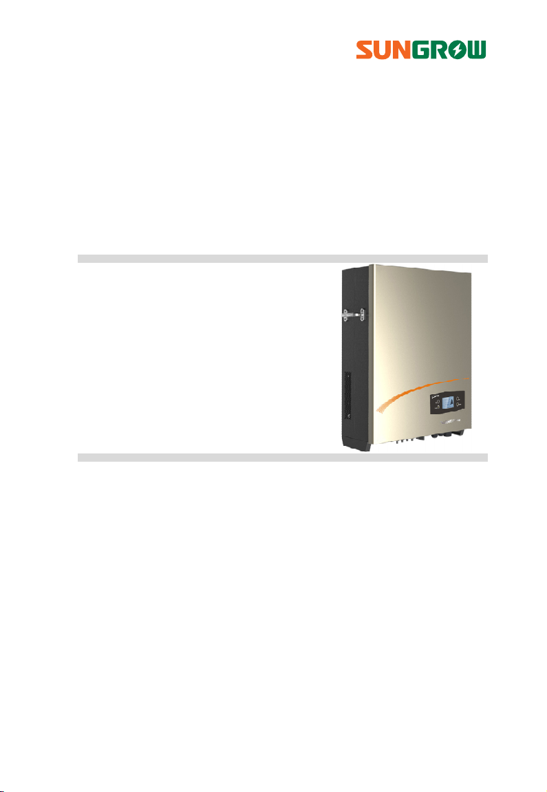
Quick User Manual
SG8KTL-EC/SG10KTL-EC/
SG12KTL-EC
PV Grid-Connected Inverter
SG8_10_12KTL-ECV11-QUEN-Ver15-201508 Version: 1.5
Page 2

Page 3

All Rights Reserved
No part of this document may be reproduced in any form or by any means without
the prior written permission of Sungrow Power Supply Co., Ltd.
Trademarks
and other Sungrow trademarks used in this manual are owned by
Sungrow Power Supply Co., Ltd.
All other trademarks or registered trademarks mentioned in this document owned
by their respective owners
Notice
The contents of the manual will be periodically updated or revised due to the
product development. Specifications are subject to changes without advance
notice!
The latest manual can be acquired via www.sungrowpower.com.
Contact Information
Should you have any question about this product, please contact us.
Company: Sungrow Power Supply Co., Ltd.
Website: www.sungrowpower.com
Email: [email protected], [email protected]
Address:
Zip: 230088
Telephone: +86 551 6532 7834, +86 551 6532 7845
Fax: +86 551 6532 7856
No.1699 Xiyou Rd., New & High Technology Industrial Development
Zone, Hefei, P. R. China.
I
Page 4
About this manual
This quick user manual provides a general instruction required for installing, wiring,
commissioning and operating the SG8KTL-EC, SG10KTL-EC and SG12KTL-EC
inverters.
SG8KTL-EC, SG10KTL-EC and SG12KTL-EC will be referred to as inverter hereinafter
unless specified otherwise.
For further instructions on installing or operating, please refer to the
detailed user manual which you can require on the package CD or via
www.sungrowpower.com.
To prevent personal injury or material damage, the inverter must only be installed,
operated, maintained and serviced by qualified personnel:
They must be trained specially;
They have already read over and understood the manual and other related
documents;
They have been familiar with safety requirements for electrical system and local
safety-related guidelines.
The contents of the manual will be periodically updated or revised due to the
product development. Specifications are subject to changes without advance
notice!
The latest manual can be acquired via www.sungrowpower.com.
In no case shall this quick user manual substitute for the user manual or
related notes on the devices.
Any violation could result in personal death or injury or device damage.
II
Keep this manual in a convenient place for future reference.
Page 5

Contents
About this manual .......................................................................... II
1 Safety Instructions ................................................................... 1
1.1 Symbols Explanation ............................................................................................ 1
1.2 Symbols on the Inverter Body ........................................................................... 2
1.3 Important Safety Instructions ........................................................................... 2
2 Product Introduction ............................................................... 6
2.1 Inverter Appearance ............................................................................................. 7
2.2 Unpacking and Inspecting ................................................................................. 8
3 Mechanical Installation ........................................................... 9
3.1 Select an Optimal Installation Position .......................................................... 9
3.2 Installation ............................................................................................................. 11
4 Electrical Connection ............................................................. 12
4.1 Cables Selection .................................................................................................. 12
4.2 Meter Connection (optional) .......................................................................... 13
4.3 AC Connection ..................................................................................................... 13
4.4 DC Connection ..................................................................................................... 15
4.4.1 PV Mode Configuration ....................................................................................... 15
4.4.2 DC Cables Connection ......................................................................................... 16
4.5 Second Protective Earth Terminal ................................................................. 17
4.5.1 Second PE Terminal ............................................................................................... 17
4.5.2 Second PE Connection ......................................................................................... 17
4.6 Communication Connection .......................................................................... 18
4.6.1 Interfaces Overview .............................................................................................. 18
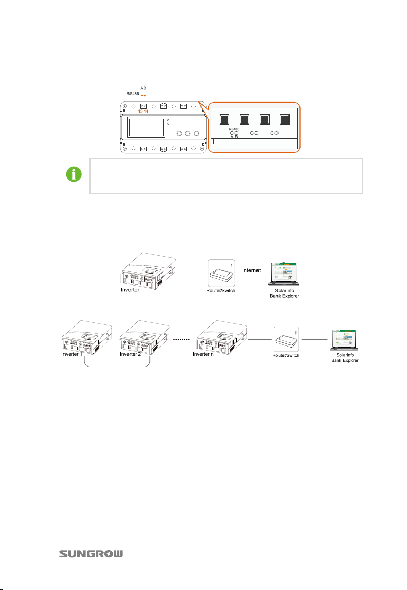
4.6.2 RS485 Communication Connection ................................................................ 18
4.6.3 Ethernet Communication Connection ........................................................... 19
4.6.4 Power Control Configuration ............................................................................. 20
III
Page 6

5 Commissioning....................................................................... 23
5.1 Description of Button Function ..................................................................... 23
5.2 Commissioning Procedure .............................................................................. 23
6 Viewing PV Plant Information ............................................... 26
6.1 SolarInfo Bank Connection ............................................................................. 26
6.2 Registration and Adding PV Plant ................................................................ 27
6.3 Viewing Information via the APP .................................................................. 31
6.3.1 Acquisition and Installation of the APP .......................................................... 31
6.3.2 SolarInfo Home APP Online Registration ...................................................... 33
6.3.3 Visit in “Remote [Login]”mode ........................................................................... 34
7 Appendix ................................................................................ 35
IV
Page 7
1 Safety Instructions
1.1 Symbols Explanation
Important instructions contained in this manual should be followed during
installation, operation and maintenance of the inverter. And they will be highlighted
by the following symbols.
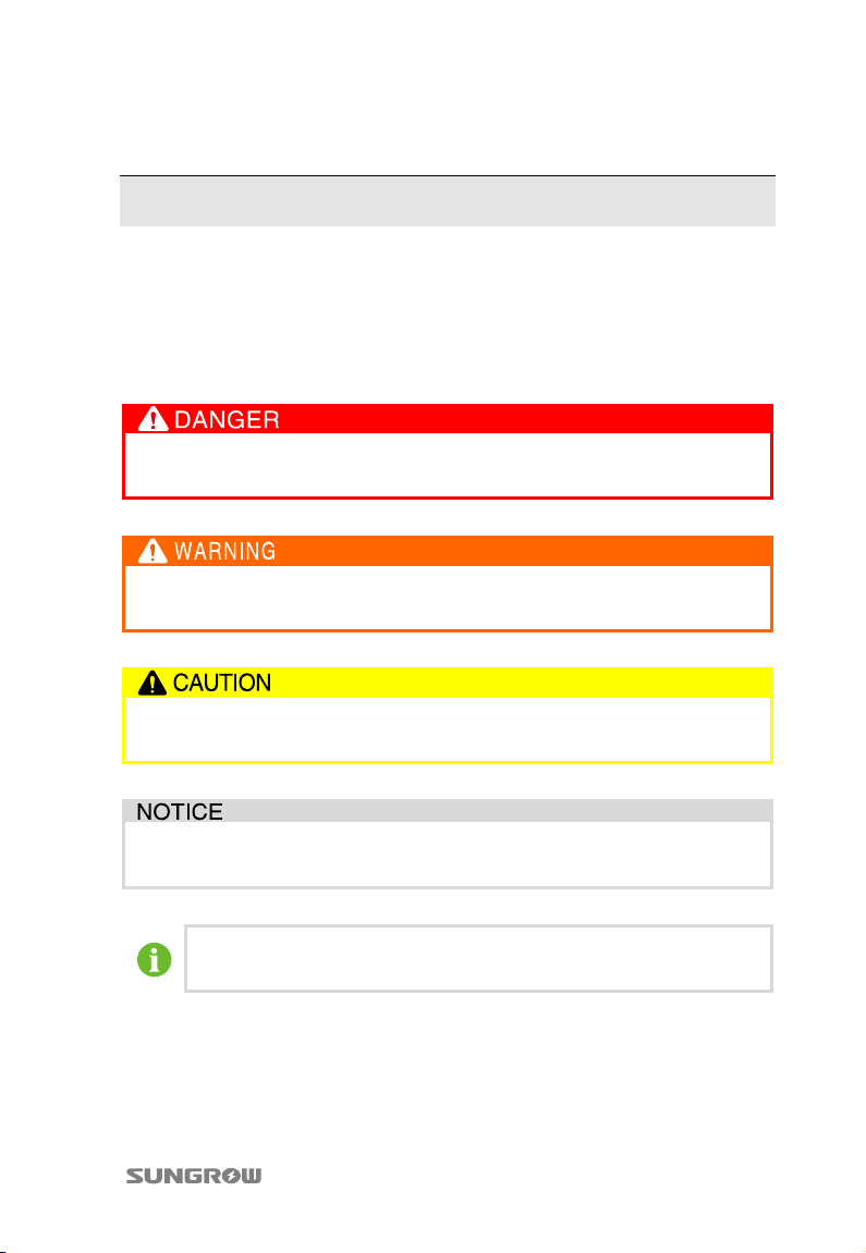
DANGER indicates a hazard with a high level of risk which, if not avoided,
will result in death or serious injury.
WARNING indicates a hazard with a medium level of risk which, if not
avoided, could result in death or serious injury.
CAUTION indicates a hazard with a low level of risk which, if not avoided,
could result in minor or moderate injury.
NOTICE indicates a situation which, if not avoided, could result in
equipment or property damage.
NOTE indicates additional information, emphasized contents or tips to
help you solve problems or save time.
1
Page 8
1 Safety Instructions Quick User Manual
1.2 Symbols on the Inverter Body
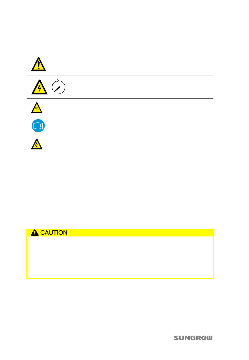
Disconnect the inverter from mains and PV generator before
service!
Do not touch any inner live parts until 10 minutes after
disconnection from the utility grid and the PV input.
Hot surface! In order to reduce the risk of burns, do not touch the
hot surface when the device is running.
Look over the user manual before any operation on the inverter!
The installation and service of the inverter unit can only be
performed by qualified personnel.
1.3 Important Safety Instructions
The inverter has been designed and tested strictly according to the international
safety regulations. As electrical and electronic equipment, safety instructions related
to them must be complied with during installation, operation and maintenance.
The following safety instructions must be read and kept in mind prior to any work.
Before Installation
There is a risk of injury due to improperly handling the device!
Always follow the instructions contained in the manual when moving and
positioning the inverter.
The weight of the device can cause injuries, serious wounds, or bruise if
improperly handled.
2
Page 9
Quick User Manual 1 Safety Instructions
During Installation
Prior to installing the inverter onto the wall, it is crucial to make certain that
the inverter is not electrically connected.
System performance loss due to bad ventilation!
The device requires good quality ventilation during operation. It is essential
to keep the unit upright and nothing covering the heat sink in order to
ensure that the device interior is well cooled down.
During Electrical Connection
PV arrays will produce electrical energy when exposed to sunlight and thus
can create an electrical shock hazard.
Wiring of the PV arrays should be performed only by qualified personnel.
All electrical connections must be in accordance with local and national
standards.
Only with the permission of the local energy sector, the inverter can be
connected into the utility grid.
All cables must be firmly attached, undamaged, properly insulated and
adequately dimensioned.
3
Page 10
1 Safety Instructions Quick User Manual
During Inverter Operation
Do not open the enclosure when the inverter is under voltage. There is an unlikely
but possible risk of explosion in very specific cases of malfunction. The enclosure
will protect persons and property from such an explosion, only if it is correctly
sealed.
There is a risk of inverter damage or personal injury!
DO NOT disconnect DC connectors while the inverter is under AC load! First
de-energize the device from dual power sources and then verify that there is
no voltage present.
There is a risk of burn!
DO NOT touch the device hot parts (such as heat sink) during operation.
Only LCD display panel and DC switch can be touched during inverter
operation.
Maintenance and Service
Before any service work, you should obey the following procedures.
Disconnect inverter from the utility grid first and then PV arrays;
Wait at least 10 minutes until the inner capacitors discharge completely;
Verify that no voltage or current is present with appropriate testing
device.
Keep non-related persons away!
A temporary warning sign and barrier must be posted to keep non-related
persons away in any period while performing electrical connection and
service work.
4
Page 11
Quick User Manual 1 Safety Instructions
Any malfunction that may impair the inverter safety functions must be
repaired immediately before the inverter is restarted.
Inverter contains no owner serviceable parts inside. Please contact local
authorized personnel if any service work is required.
Servicing of the device in accordance with the manual should never be
undertaken in the absence of proper tools, test equipments or more
recent revision of the manual which is clearly and thoroughly
understood.
There is a risk of inverter damage if it is improperly serviced.
Use only accessories and spare parts approved by the inverter
manufacturer. Never modify the inverter or its components. Otherwise it
will cause loss of any or all warranty rights.
Others
The selected country settings can be changed only by qualified personnel!
Unauthorized modification to country settings should be prohibited.
Alternation of the country settings may cause a breach of the
type-certificate marking.
All safety instructions, warning labels and nameplate on the inverter body:
Must be clearly visible;
Must not be removed, covered and pasted.
5
Page 12
2 Product Introduction
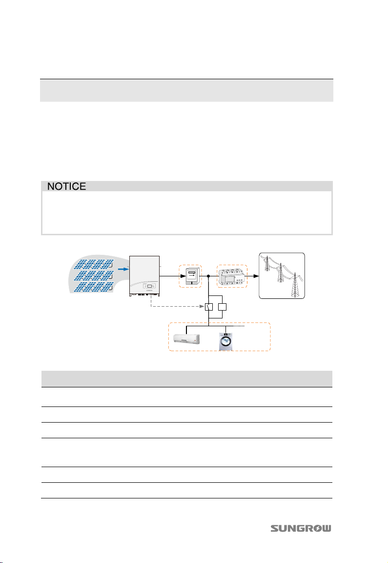
The inverters, which are 3-phase string inverters without transformer, are crucial
units between the PV strings and utility grid in the small-scaled PV power system.
The intended usage of the inverter is illustrated in Fig.2-1.
By setting the upper limit of feed power, the inverter will run with power derating
once the meter detects that the output power is greater than the set value.
Any other or additional usage is not permitted except the intended usage.
Where the positive or negative terminal of PV strings needs to be grounded,
inverter cannot be connected to PV modules.
Grid Dispatch Center
CD
AB
Control signal
K
E
Household Load
Fig. 2-1 Inverter Application in the PV Power System
F
Item Description Remark
A PV strings
Monocrystalline silicon, polycrystalline silicon, and
thin-film of protection class II without grounding
B Inverter SG8KTL-EC, SG10KTL-EC and SG12KTL-EC
C Metering device Meter cupboard with power distribution system
D Smart energy
meter (optional)
Three-phase electronic energy meter, used to measure
the active power output. Communicate with the
inverter via RS485 port.
E Utility grid TT, TN-C, TN-S, TN-C-S.
F Household load Household appliances.
6
Page 13
Quick User Manual 2 Product Introduction
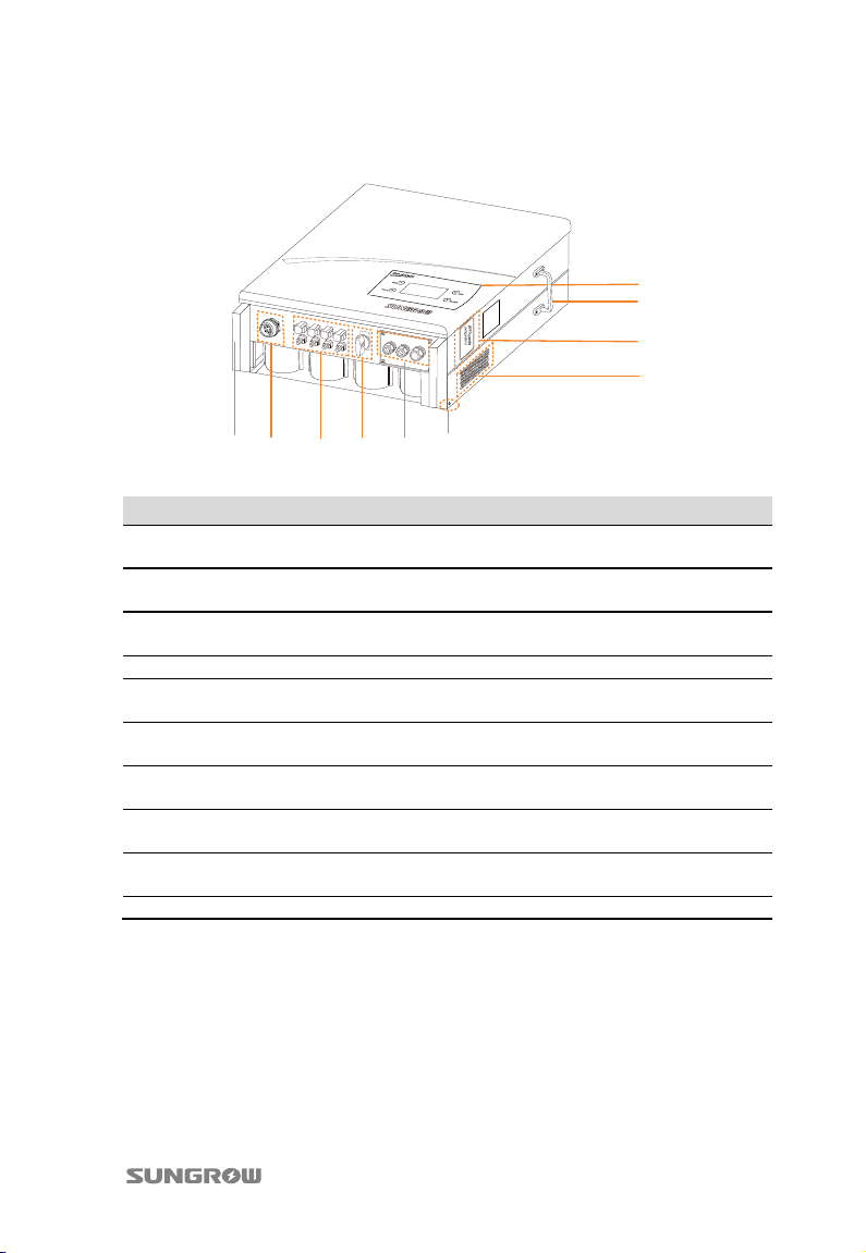
2.1 Inverter Appearance
1
2
3
4
1065 7 8 9
Fig. 2-2 Inverter Appearance
No. Name Description
1 LCD display panel Human-computer interaction interface for looking up
2 Side grips The side grips are designed for holding the unit when
3 PV input parallel lid
(SG12KTL-EC)
4 Ventilation holes To ensure sufficient heat dissipation.
5 Handles The handles are designed for transporting, installing
6 AC connection
terminal
7 DC terminals There are four pairs of DC terminals for PV inputting
8 DC switch During normal operation it is in “ON” state. It can shut
9 Communication
connection terminals
10 Second PE terminal As specified in EN 50178.
running information and configuring parameters.
mounting, moving or servicing the inverter.
There are two parallel blocks for PV input mode
configuration under the lid.
and dismantling the inverter.
Inverter feeds power to utility grid via this terminal.
on the bottom of the inverter.
down the inverter immediately in “OFF” position.
They are RS485 communication ports, Ethernet
communication ports and DI/DO ports.
7
Page 14
2 Product Introduction Quick User Manual
2.2 Unpacking and Inspecting
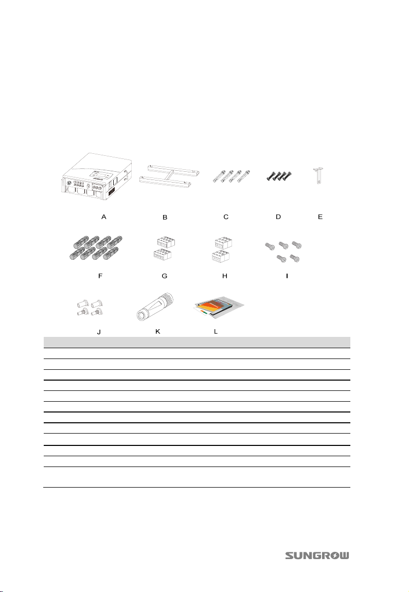
1. Unpack the carton and take out all the accessories.
2. Inspect the inverter for visible damages and check the completeness of the
delivery contents according to the inner packing list.
3. Contact your supplier if the delivery is incomplete or damaged. The inverter
is unavailable if any damage is detected.
Item Description
A Inverter.
B Wall bracket used to mount inverter onto the wall.
C Expansion bolts for fastening wall bracket onto concrete wall.
D Fastener set for installing wall bracket onto metal frame.
E Theft-proof device used to lock the inverter to the wall bracket.
F PV input connectors, including positive and negative connectors.
G Four-pole plugs for DI connection.
H Three-pole plugs for DO connection.
I Five M4 screws for second PE connection and spare.
J Two pairs. Seal the unplugged PV connectors with sealing caps.
K AC connector.
L Related documents, including quality certificates, quick user manual, CD,
8
packing list and product test reports.
Page 15
3 Mechanical Installation
3.1 Select an Optimal Installation Position
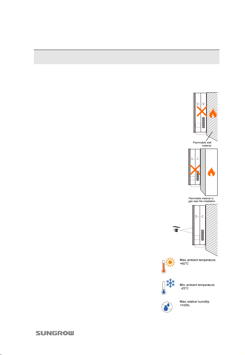
The inverter must be mounted in a vertical site.
This requires a firm wall or metal frame.
Mount the inverter at an appropriate site without
flammable material and flammable gas nearby.
Install the inverter vertically with upside up at eye
level for easily buttons operation and display
reading.
The inverter unit with IP65 can be installed indoors
or outdoors where the ambient temperature and
relative humidity meet the requirements.
9
Page 16
3 Mechanical Installation Quick User Manual
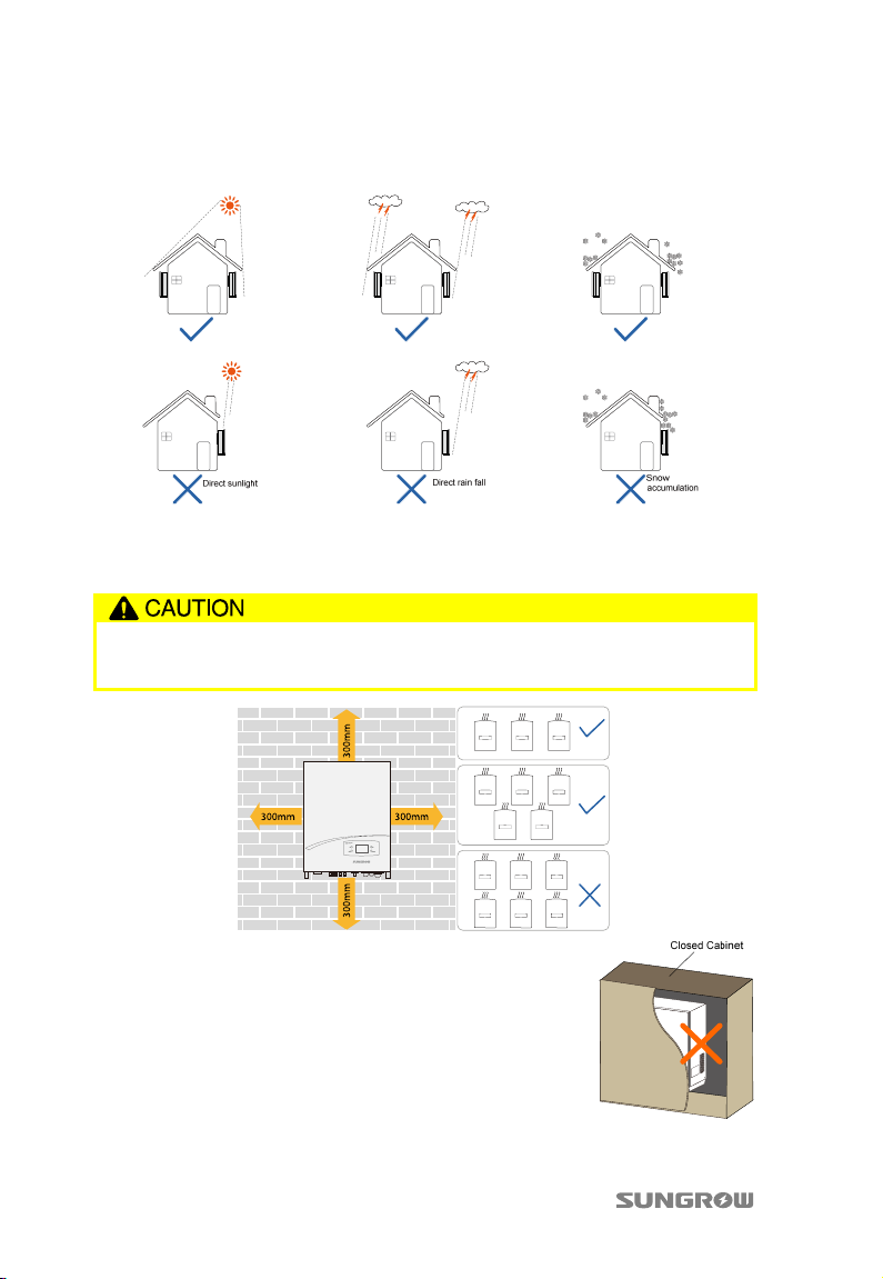
Avoid exposing the inverter to direct sunlight or rain or snow! Shaded site of the
building would be better.
Take enough space for convection into consideration during installing multiple
inverters. It is suggested to position the multiple inverters in a staggered way if
necessary.
The device requires good quality ventilation during operation. System
performance loss due to bad ventilation!
Do not install the inverter in a enclosed cabinet.
10
Page 17
Quick User Manual 3 Mechanical Installation
T
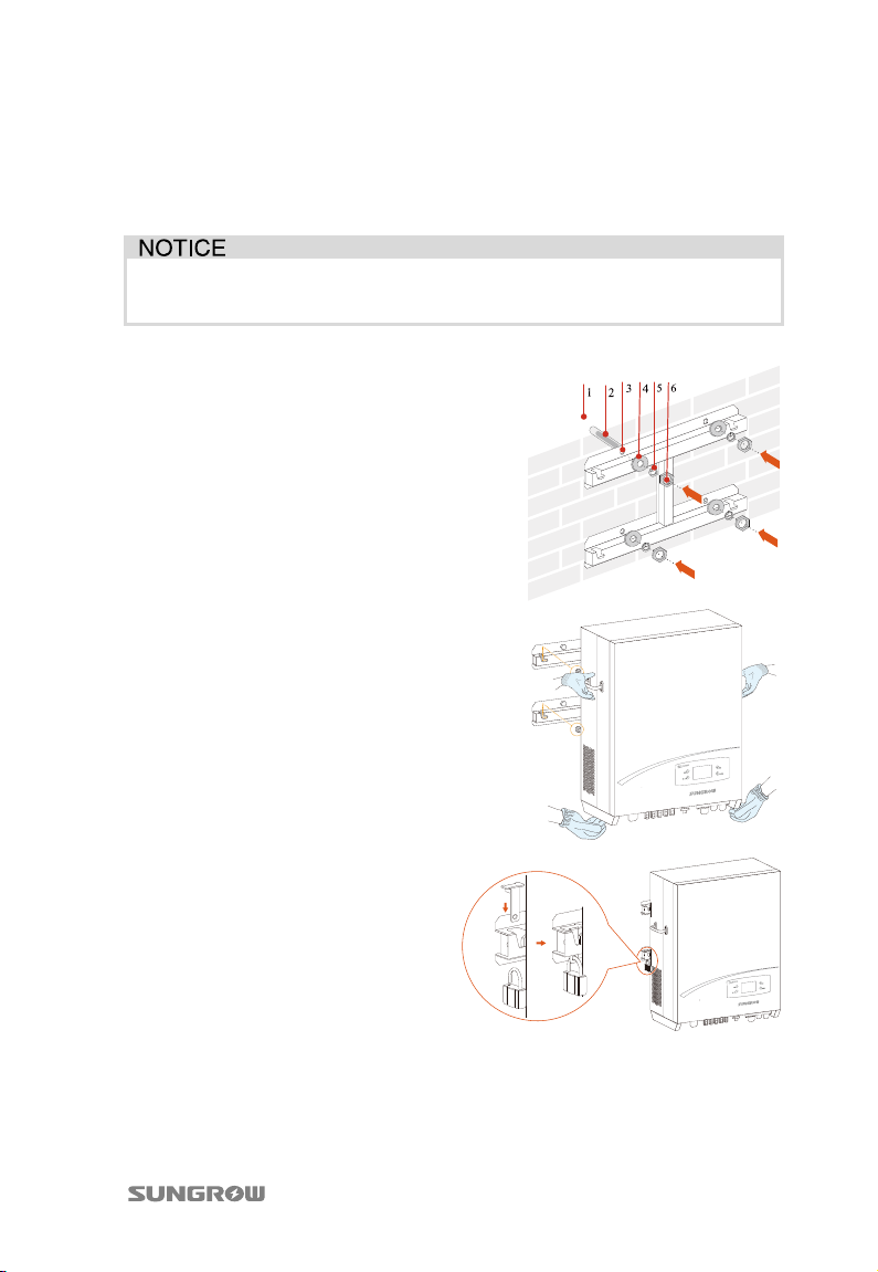
3.2 Installation
1. Move the inverter to the installation site with the help of another person or
the lifting device by means of the side grips.
Always keep in mind the weight of the inverter! The Installers should wear
gloves to avoid scratches when moving and mounting the inverter.
2. Fix the backplate on the wall
with appropriate fixing sets.
3. Mount the inverter onto the
backplate and secure it with a
M6×16 theft-proof screw.
4.
o protect the inverter from
theft, you can lock it to the wall
bracket with a theft-proof
device and a padlock.
11
Page 18
4 Electrical Connection
Death hazards due to high voltage inside the inverter!
Make sure that all the DC and AC cables to the inverter are not live before
the electrical work.
Do not turn on the AC or DC circuit breaker until all inverter electrical
connections have completed.
Do not open the enclosure when the inverter is under voltage.
There is a risk of inverter damage or personal injury!
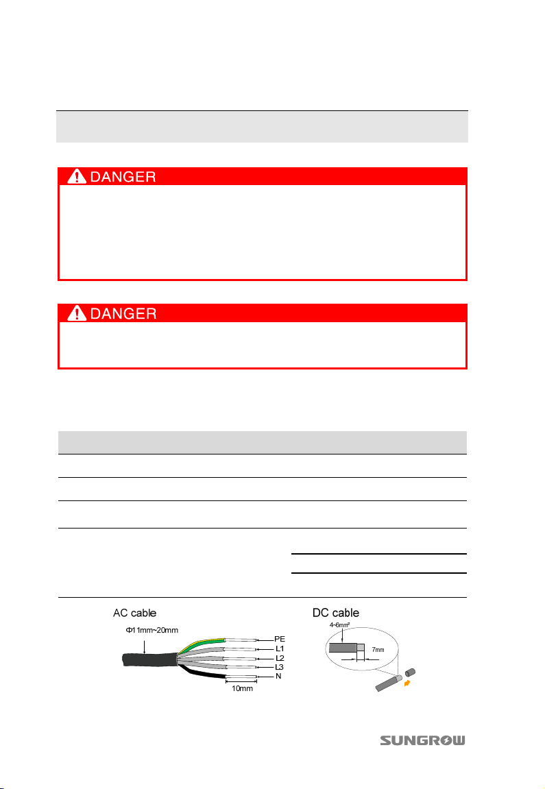
4.1 Cables Selection
Cable Type Single Conductor size Recommended conductor size
AC cable 4…10 mm²(AWG11…AWG7) ---
DC cables 4…6 mm²(AWG11…AWG9) ---
Second PE
Cable
Comm. cables
12
--- 6 mm
Shielded network cable ---
DI connection cable 5 cores cable(5×0.94 mm2)
DO connection cable 4 cores cable(4×2.5 mm2)
2
Page 19
Quick User Manual 4 Electrical Connection
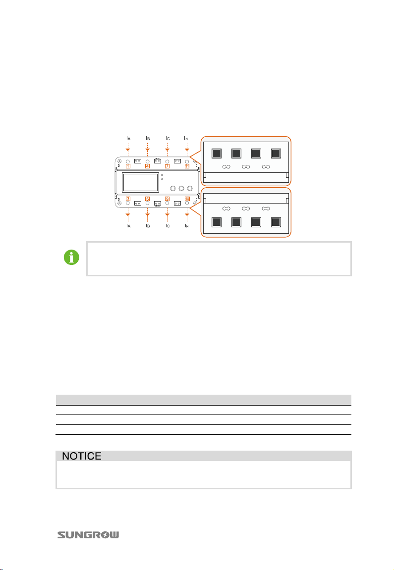
4.2 Meter Connection (optional)
The smart energy meter is installed between the air breaker and the grid. It
measures the feed-in power and communicates with the inverter through RS485
connection. This section describes the power cables connection of the meter.
The following figure shows the cable requirements and connection.
The recommended cross-section area of conductor is 16 mm2.
The length of insulation to be stripped off is 10 mm~13 mm.
*Image shown here is for reference only. For the detailed information, see the user
manual of meter.
4.3 AC Connection
AC Circuit Breaker
An independent three or four-pole circuit breaker for the inverter must be installed
at the output side to ensure that the inverter can be securely disconnected under
load.
Inverter Type Specification for AC Circuit Breaker
SG8KTL-EC 30A
SG10KTL-EC 30A
SG12KTL-EC 32A
It is not allowed for several inverters to use the same circuit breaker.
It is not allowed to connect loads between inverter and circuit breaker.
13
Page 20
4 Electrical Connection Quick User Manual
Connecting Inverter to AC Grid
Danger to human life due to high voltage inside the inverter!
Make sure that all the DC and AC cables to the inverter are not live before
the electrical work.
Do not turn on the AC circuit breaker until all inverter electrical connections
have completed.
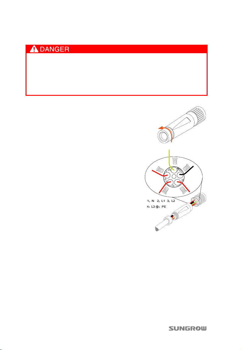
1. Unscrew the water-proof terminal in the
following direction.
2. Insert appropriate size AC cables into the
water-proof terminal.
3. Strip off insulation layer of all AC cables.
The length of strip insulation is
approximately 10 mm.
4. Fix all cables ends to the corresponding
terminals with the torque of 1 Nm
according to markings on the connector,
especially “PE” cable. If a phase wire is
connected to the “PE” terminal, the
inverter may not function properly.
5. Pull cables outwards to confirm whether they are installed firmly.
6. Combine the two front-end parts together with the torque of 2 Nm.
7. Tighten the water-proof terminal with the torque of 5 Nm in opposite
direction.
8. Make sure the AC and DC circuit breakers are disconnected.
9. Connect phase cables and “N” cable to AC circuit breaker.
− Plug AC connector to corresponding AC terminal.
− Screw AC cables except the “PE” cable to the AC circuit breaker.
10. Connect AC circuit breaker to utility grid.
11. Make sure all AC cables are firmly installed.
14
Page 21
Quick User Manual 4 Electrical Connection
4.4 DC Connection
4.4.1 PV Mode Configuration
The two PV inputs can be configured in independent mode or parallel mode. Refer
to the user manual for an appropriate mode selection.
In independent mode, when there is only one PV input, the other input may
produce induced voltage. DO NOT touch the unused DC terminals.
Independent Mode
For independent mode, the two PV inputs work independently, each with its own
MPPT. Therefore the two PV inputs can be different from each other in PV module
types, numbers of PV panels in PV string, tilt angles and orientation angles of PV
modules.
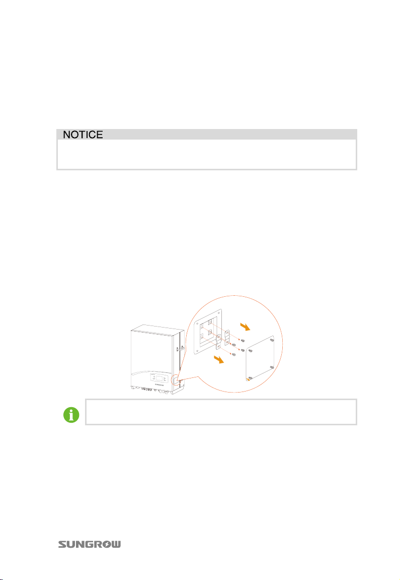
SG12KTL-EC is set in parallel mode by default. If you want to configure it to
independent mode, please remove copper bars between the two terminal blocks
and tighten the PV input parallel lid back to the inverter. Meanwhile refer to “5.2
Commissioning Procedure” to modify the configuration mode.
Keep the copper bars in a convenient place for future use.
Parallel Mode
For parallel mode, all PV strings with the same type, the same number, identical tilt
and identical orientation in series can be connected to each single input area. Two
trackers are configured in parallel by Y-type cable connector terminal to handle
power and/or current levels higher than those a single tracker can handle.
15
Page 22
4 Electrical Connection Quick User Manual
For SG8KTL-EC and SG10KTL-EC, the default configuration mode of the LCD screen is
independent mode. If you want to configure it to parallel mode, please refer to “5.2
Commissioning Procedure” to modify the configuration mode.
4.4.2 DC Cables Connection
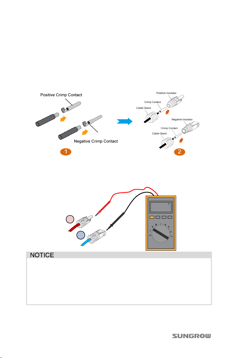
1. Assemble the DC plug-in connectors and connect them to the bottom
terminals.
2. Check the polarity of the PV input before PV input connection and that the
open-circuit voltage does not exceed the inverter input limit 1000 V, even
under the lowest operating temperature. Refer to module specification
supplied by module manufacturer for detailed information.
480.0
+
-
The inverter will not function properly if the DC polarities are reversed.
Check the positive and negative polarity of the PV cells. After confirmation,
you can insert the DC connectors into the input terminals on the bottom of the
inverter.
For the same MPPT, reverse connection of a single string is prohibited. A
permanent failure of the system or inverter may follow if otherwise.
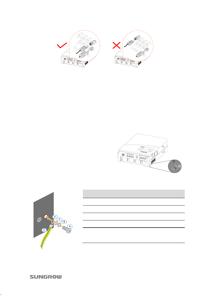
3. Plug the positive and negative DC connectors into PV terminals underneath
the connection cabinet until there is an audible sound.
16
Page 23
Quick User Manual 4 Electrical Connection
T
4. One pair of DC terminals in DC1 input and DC2 input must be short-circuited
by Y-type cable connector terminal. (For SG8KTL-EC and SG10KTL-EC)
5. Seal the unused DC terminals with the terminal caps.
4.5 Second Protective Earth Terminal
The inverter is equipped with second protective earth terminal as specified in EN
50178.
4.5.1 Second PE Terminal
here is a second PE terminal on the right
side of the inverter. You may choose to
connect PE connection.
4.5.2 Second PE Connection
Item Description Specification
A Screw M4
B Spring washer -
C Washer D Cable socket -
Yellow-green
E
cable
*The connection parts are not included in the delivery scope.
6-10 mm
10-16 mm
wire
2
copper wire or
2
aluminum
17
Page 24
4 Electrical Connection Quick User Manual
4.6 Communication Connection
4.6.1 Interfaces Overview
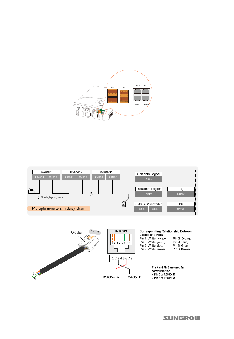
All communication terminals are located on the bottom of the inverter.
4.6.2 RS485 Communication Connection
Where there is more than one inverter, all inverters can be connected in a “daisy
chain”. The very first and last inverters in the chain must be terminated with a
resistor of 120 Ω. The shielding layer of network cable should be single-point
grounded.
For RJ45 Connection the pins definitions are shown below:
18
Page 25
Quick User Manual 4 Electrical Connection
The following figure shows the RS485 connection to the three-phase smart energy
meter.
The length of insulation to be stripped off is 5 mm~7 mm.
The wires 3 and 6 are connected to terminals A and B respectively.
4.6.3 Ethernet Communication Connection
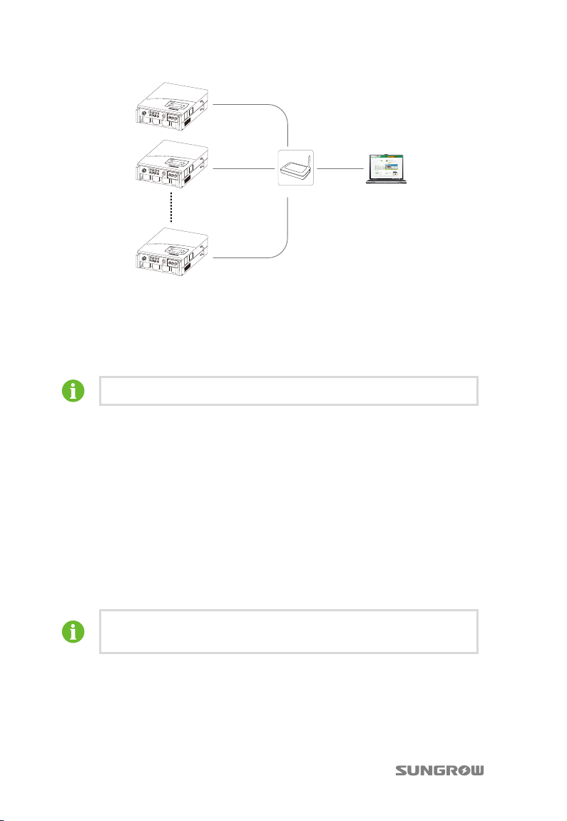
The Ethernet communication can be connected either in single, daisy chain or star
topology.
Fig. 4-1 Single inverter network connection
Fig. 4-2 Inverters network connection in daisy chain topology
The network communication of the daisy chain is done via the inverter in-built
switching chip. Therefore, when the inverter is damaged or enters the low power
consumption status, the switching chip cannot work normally and the daisy chain
communication will be interrupted.
19
Page 26
4 Electrical Connection Quick User Manual
Inverter 1
Inverter 2
Inverter n
Router/Switch
Fig. 4-3 Inverters network connection in star topology
SolarInfo
Bank Explorer
The star topology network connection is recommended for optimal operation.
The maximum number of inverters connected depends on switch, router and other
factors. Please refer to switch’s or router’s manual to obtain the limit.
The Network cable should be less than 100 m.
4.6.4 Power Control Configuration
There are two terminals located on the bottom of the inverter for power control
configuration: DI and DO.
Power Control Settings
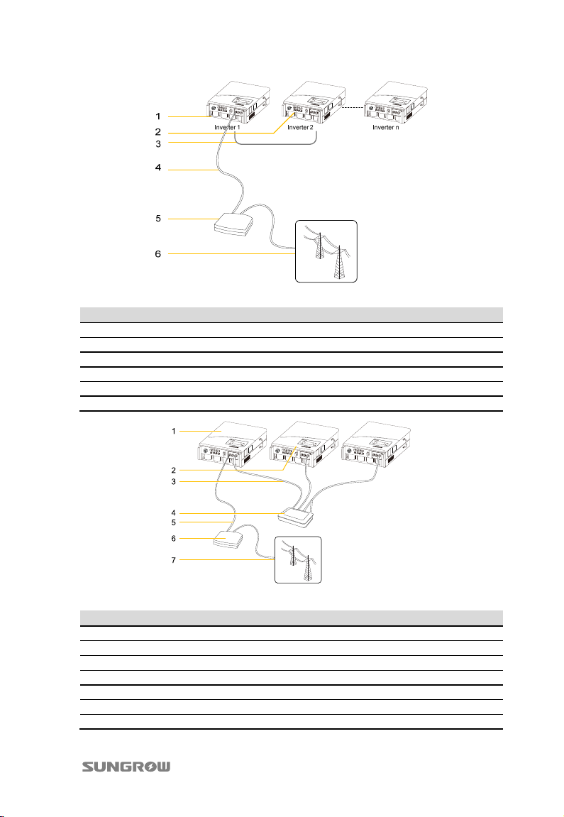
The inputs of DI can be used to connect a ripple control receiver for active power
control.
The inverters then can be linked via Ethernet/RS485 so that the inverter connected
to the ripple control receiver can transmit the information received to the other
inverters.
In the Ethernet communication connection, only one inverter can be
set as master inverter, others shall be set as slave inverters.
20
Page 27
Quick User Manual 4 Electrical Connection
Fig. 4-4 Connecting the ripple control receiver for inverters with RS485 connections
Item Description
1 Master inverter
2 Slave inverter
3 RS485 connection
4 5-conductor connection at digital input
5 Ripple control receiver
6 Grid
Fig. 4-5 Connecting the ripple control receiver for inverters with Ethernet connections
Item Description
1 Master inverter
2 Slave inverter
3 Ethernet cable
4 Router
5 5-conductor connection at digital input
6 Ripple control receiver
7 Grid
21
Page 28
4 Electrical Connection Quick User Manual
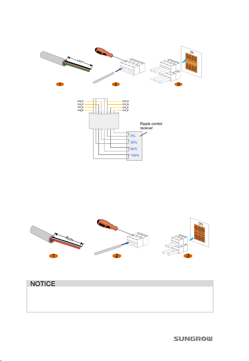
Connect the cables to DI terminal block according to the terminal assignment:
Connect the ripple control receiver to the inverter.
DO Relay Configuration
The inverter has two DO relays, with functions as follows:
− DO1: Grounding fault alarm (not configurable)
− DO2: Consumer load control
Connect the cables to DO terminal block according to the terminal assignment:
The DO2 relay can be configured as NO (by connecting COM and OFF) or NC (by
connecting COM and ON) contact. The DO1 is not configurable.
You must install an external load relay between the inverter and the
consumer load. Do not connect any consumer load directly to the switch
output.
22
Page 29
5 Commissioning
Before starting the inverter, make sure all installation and connections are
completed and verified.
5.1 Description of Button Function
Inverter offers two buttons for the user to look up the running information and
configure parameters settings. The two buttons have multiple functions. Please refer
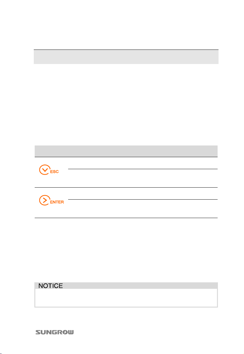
to Tab. 5-1before any operation onto inverter.
Tab. 5-1 Button Function
Button Operation Description
Press less than
one second
Press more than
one second
Press less than
one second
Press more than
one second
Move upwards or downwards, or increase setting
value. Hereafter, it is referred to as “Press ”.
Return to the previous menu or cancel the
command. Hereafter, it is referred to as “Press
ESC”.
Move left or right, or turn pages. Hereafter, it is
referred to as “Press ”.
Enter into the sub-screen or confirm the
command. Hereafter, it is referred to as “Press
ENTER”.
5.2 Commissioning Procedure
1. Connect the external AC circuit breaker.
2. Rotate DC switch to the “ON” position.
3. Supposed that there is sufficient sunlight and DC power, the inverter begins
to initialize and the LCD is activated to setup the interface. Press buttons to
configure initial inverter parameters.
Only qualified personnel are allowed to adjust or set parameters related to
system protection functions.
23
Page 30
5 Commissioning Quick User Manual
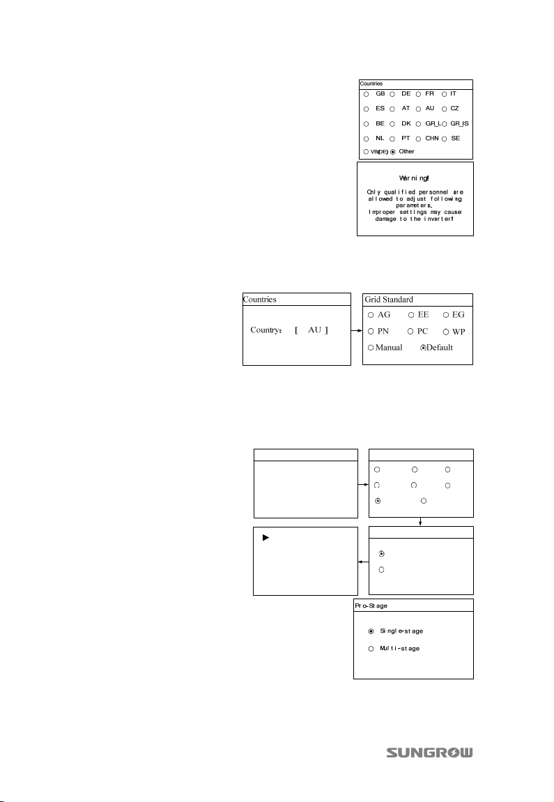
4. Perform country settings with the right
two buttons. Confirm the settings by
Pressing
ENTER.
5. Each country code represents
corresponding local protective
parameters that have been preset
before delivery. After country setting,
there is the warning screen.
6. (Optional) When the country code “AU” is selected, Press ENTER to enter
the “Grid Standard” interface. Press
/ to choose the correct grid standard.
Press ENTER to confirm the choice.
7. (Optional) When the country code “AU” and the grid standard “Manual” are
selected, Press ENTER to enter the “Pro-Stage” interface. Press
/ to
choose the correct stage. Press to move cursor and Press to scroll up
time value. Confirm the settings by Pressing ENTER. The following figure
shows the settings of single-stage protection parameters.
Countries
Country:
[ AU ]
Grid Standard
AG EE EG
PN PC
Manual Default
WP
Vgrid-max 260.0V
Vgrid-min 210.0V
Fgrid-max 52.00Hz
Fgrid-min 47.00Hz
Pro-Stage
Single-stage
Multi-stage
8. For other countries except “AU”,
configure the protective parameters
settings.
24
Page 31
Quick User Manual 5 Commissioning
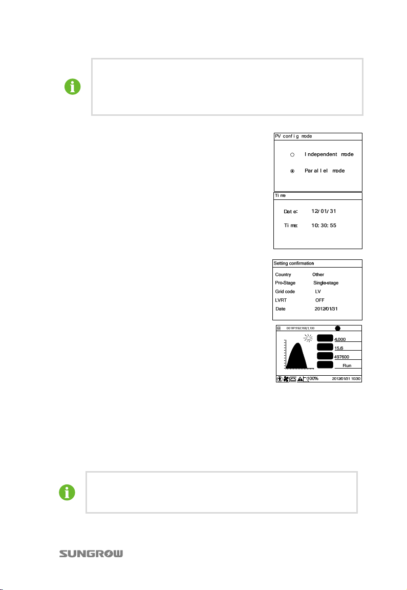
Single-stage protection: There is only one protection threshold range
for each grid voltage protection parameter.
Multi-stage protection: The protection parameters for each grid
voltage protection can be set with two threshold ranges.
9. Set PV configure mode on LCD according to
the actual PV string configuration.
10. Configure time according to the local time.
The date format is YY/MM/DD. YY, MM, and
DD stand for year, month, and day
respectively. The time format is hh/mm/ss.
hh, mm, and ss stand for hour, minute, and
second respectively.
11. After configuring all parameters, there will be
a “setting confirmation” screen. Check
whether all above-mentioned parameters are
correct. Confirm by Pressing
by Pressing
ESC and reset.
ENTER. Cancel
12. When the initial configuration is
completed, inverter will enter into startup
process. Observe the status of LED
indicators and the LCD main screen. If
inverter’s commissioning succeeds, the
“RUN” indicator will be lit and “RUN” will be
displayed on the “State” area. If inverter’s
commissioning fails, the “FAULT” indicator
will be lit and “FAULT” will occur on the
display. Press to view “current fault”
information. Refer to the user manual for
troubleshooting. Repeat the above
procedures for inverter commissioning.
If you need to modify the parameters after successful commissioning,
re set them t hroug h the “Set- param” menu w ith the p a ssword 111111.
For details, see the user manual.
25
P(%)
110
50
0
5 8 11 14 2017 23
B
P-ac
E-day
E-tot
State
t
kW
kWh
kWh
kW
h
kW
h
Page 32
6 Viewing PV Plant Information
After registering on the webpage www.solarinfobank.com, users can view PV plant
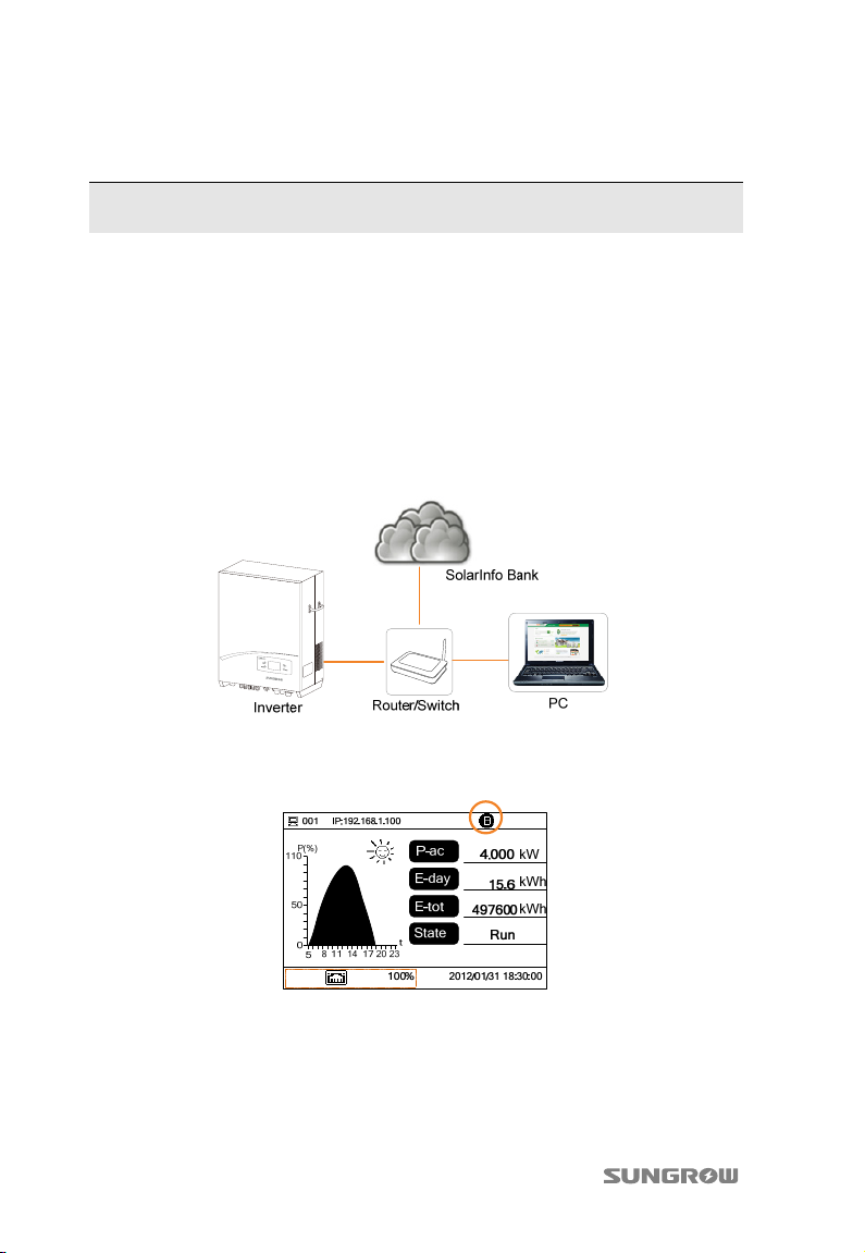
information through the computer or smartphone. Users can also view PV plant
information through the APP of SolarInfo Home installed into the smartphone.
6.1 SolarInfo Bank Connection
1. Connect the communication cable between router and inverter, and connect
the communication cable between router and PC.
2. Wait for about 10 minutes and the icon as shown in the figure below will
appear on the main LCD display interface. The SolarInfo Bank connects to the
inverter successfully.
3. Open the explorer, input the webpage www.solarinfobank.com in the
address bar. Register and then visit SolarInfo Bank. For details, see “6.2
Registration and Adding PV Plant”.
4. View the plant information via SolarInfo Home APP, see “6.3 Viewing
Information via the APP”.
26
Page 33
Quick User Manual 6 Viewing PV Plant Information
6.2 Registration and Adding PV Plant
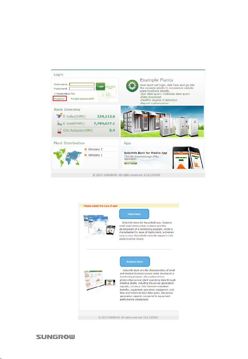
1. Open a browser and enter the URL www.solarinfobank.com to view the
homepage of SolarInfo Bank. Register a new user by clicking “Register”.
2. The registration interface as shown below will appear. User can select Home
users or Business users according to real situation. Select Home users for
residential use. Select Business users for commercial use.
27
Page 34
6 Viewing PV Plant Information Quick User Manual
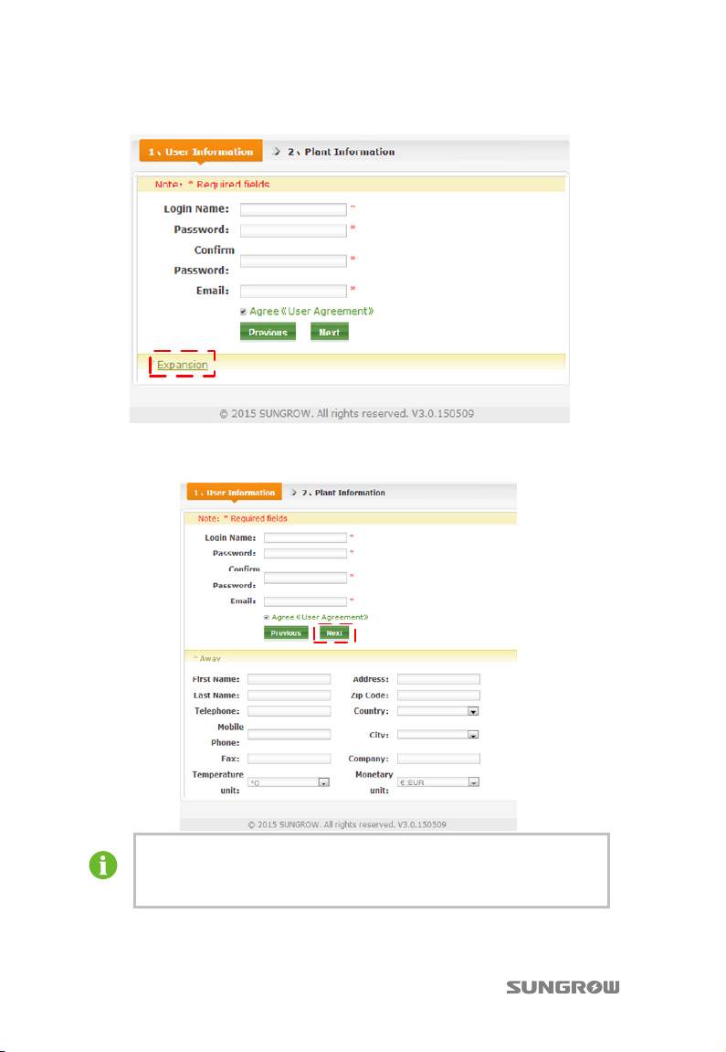
3. Fill in the user information in the following interface.
Click Expansion to fill in more information in the following interface. Then click
Next.
The Country, City, Monetary unit and Temperature unit can be
selected from the drop-down list. For other items, user must fill in
manually.
28
Page 35
Quick User Manual 6 Viewing PV Plant Information
T
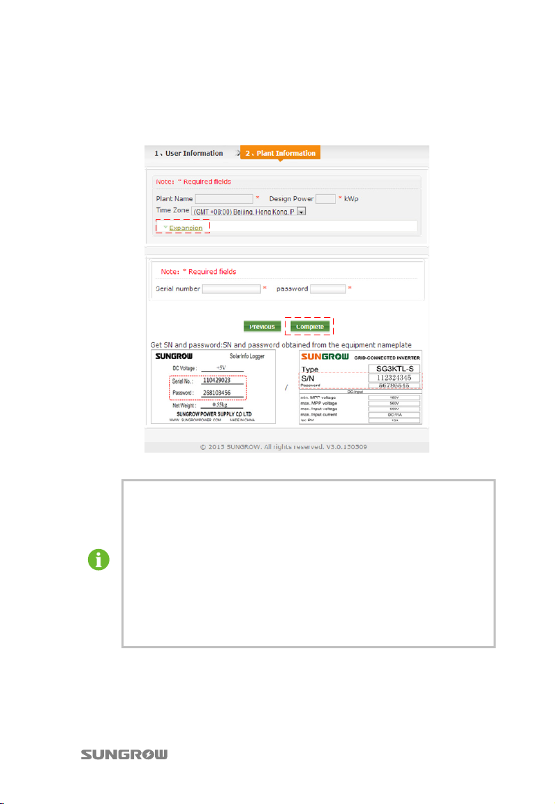
4. Fill in the plant information in the following interface. Click Expansion to fill
in more information. Click Complete to finish the registration and click
Previous to return to the previous page to modify information. If the Home
users is selected in step 2, the registration process is finished by now.
*The nameplate in the figure is for reference only.
ime Zone must be selected according to the installation place of the
inverter. If user does not know the local time zone, please check in
Google Map.
If new devices are added, please fill in the pertinent information in the
following format:
− Serial number: the serial number shown on the device nameplate.
− Password: the same as the serial number and should be input
manually.
− Device name: the same as the device serial number by default and
can be changed by the user.
29
Page 36
6 Viewing PV Plant Information Quick User Manual
T
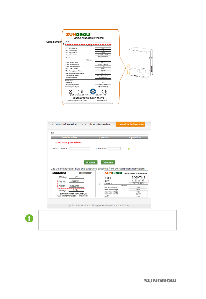
5. Proceed as follows to fill in the Device Information if the Business users is
selected in step 2.
he format of Serial number, Password, and Device name are the same
as that in Step 4. Click Complete to finish the registration and click
Previous to return to the previous page to modify information.
6. Refresh the webpage www.solarinfobank.com, then you can see the data of
the corresponding PV plant. For detailed information about the items, see
“SolarInfo Bank User Manual”.
30
Page 37
Quick User Manual 6 Viewing PV Plant Information
6.3 Viewing Information via the APP
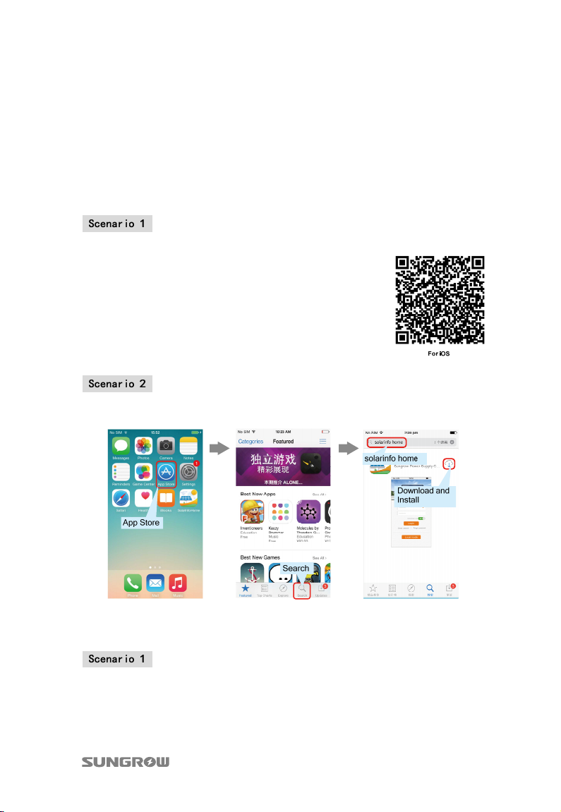
6.3.1 Acquisition and Installation of the APP
Download the SolarInfo Home APP and install it into your smartphone. You can
select the APP version for iOS or Android.
For iphone (iOS)
The address for downloading SolarInfo Home APP
is
https://itunes.apple.com/us/app/solarinfo-home/i
d906260039?l=zh&ls=1&mt=8. You can also use
your smartphone to scan the OR code as shown
on the right to download and install it.
Search for SolarInfo Home in your APP Store. Download and install it.
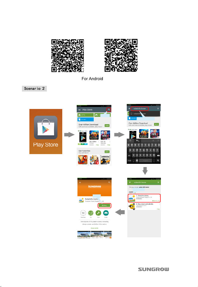
For other smartphones (Android)
The address for downloading SolarInfo Home APP is
https://play.google.com/store/apps/details?id=com.sungrow.home.or
Http://www.solarinfobank.com/app/SolarInfoHome_v1.0.apk. You can also use your
31
Page 38
6 Viewing PV Plant Information Quick User Manual
smartphone to scan the following OR codes to download and install it.
Search for SolarInfo Home in your Play Store. Download and install it.
Search
Install
solarinfo home
Download
32
Page 39
Quick User Manual 6 Viewing PV Plant Information
T
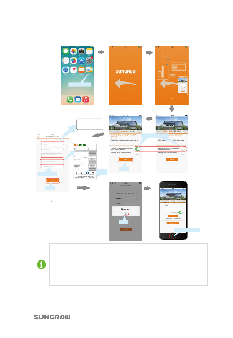
6.3.2 SolarInfo Home APP Online Registration
The same as the SN
SolarInfo Home
NOTE
Please enter your e-mail
account and the password.
Inverter
Nameplate
Submit
he username and password of the APP and webpage
Slide left
Next
OK
Slide left
Slide right(Yes)
Press HOME button
www.solarinfobank.com are generic.
You can use the registration information of webpage to login APP only
when the user type selects “Home Users” during registration.
Inquire the inverter SN and password from the nameplate. If the
password is not displayed on nameplate, it’s the same as the SN.
33
Page 40
6 Viewing PV Plant Information Quick User Manual
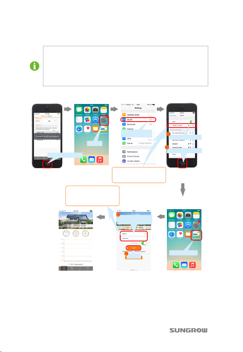
6.3.3 Visit in “Remote [Login]”mode
The SolarInfo Home APP can be visited only in “Remote [Login]” mode.
In “Remote [Login]” mode, you need configure the inverter to connect it
to your router and complete registration. Then you can log into SolarInfo
Home via the Internet to view the device running information anywhere.
Make sure that the inverter can access to the Internet.
If you want to check the running information via Internet in “Remote [Login]” mode,
please follow the steps below.
Press HOME button
NOTE
The account and password are
what you have registered.
Settings
Change Off to On
NOTE
The router must be connected
to the Internet.
1
Input your account
and password
2
Login
1
Select your router
2
Press HOME button
SolarInfo Home
34
Page 41
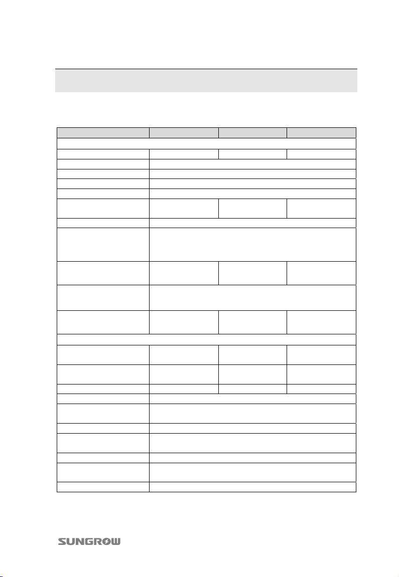
7 Appendix
Technical Data
Parameters SG8KTL-EC SG10KTL-EC SG12KTL-EC
Input Side Data
Max. PV input power
Max. PV input voltage 1000 V
Startup voltage 250 V
Nominal input voltage 610 V
MPP voltage range 200...900 V
MPP voltage range for
nominal power
No. of MPPTs 2
Max. number of PV
strings per MPPT
(DC1/DC2)
Max. PV input current
(DC1/DC2)
Max. current for input
connector
Short-circuit current of
PV input(DC1/DC2)
Output Side Data
Nominal AC output
power
Max. AC output
apparent power
Max. AC output current 11.6 A 15.3 A 19.3 A
Nominal AC voltage 3/N/PE, 230/400 Vac
AC voltage range
Nominal grid frequency 50 Hz
Grid frequency range
THD <3% (Nominal power)
Power factor
DC current injection <0.5% In
8440 W 10550 W 12650 W
320...800 V 320...800 V 350...800 V
3/1
33 A(22 A/11 A) 33 A(22 A/11 A) 36 A(24 A/12 A)
12 A
42 A(28 A/14 A) 42 A(28 A/14 A) 45 A(30 A/15 A)
8000 W 10000 W 12000 W
8000 VA 10526 VA 13300 VA
310...450 Vac
(May vary as per corresponding country’s grid standard)
45...55 Hz
(May vary as per corresponding country’s grid standard)
>0.99 @default value at nominal power, (adj. 0.8
overexcited to 0.8 underexcited)
35
Page 42
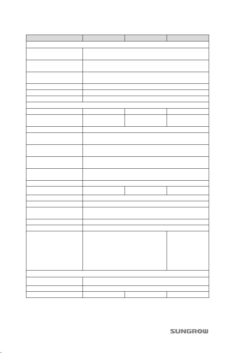
7 Appendix Quick User Manual
Parameters SG8KTL-EC SG10KTL-EC SG12KTL-EC
Protection
Anti-islanding
protection
AC short circuit
protection
Leakage current
protection
DC switch Integrated
DC fuse No
Overvoltage protection III
Yes
Yes
Yes
System
Max. efficiency 98.0% 98.0% 98.0%
Max. European
efficiency
Isolation method Transformerless
Ingress protection
rating
Night power
consumption
Operating ambient
temperature range
Allowable relative
humidity range
Cooling method Natural cooling
Noise
Max. operating altitude 2000 m
Display Graphic LCD
Communication
DC connection type MC4
AC connection type Plug and play connector
Certification
97.5% 97.6% 97.5%
IP65
<1 W
-25℃...60℃(>45℃ derating)
0...100%
≤29 dB ≤29 dB ≤35 dB
2×Ethernet, 2×RS485(RJ45 connector), 4×Digital Inputs,
VDE0126-1-1, EN62109-1, EN62109-2,
G83/1, VDE-AR-N-4105, CEI 0-21
2×Digital Outputs
VDE0126-1-1,
EN62109-1,
EN62109-2,
G59/2,
VDE-AR-N-4105,
CEI 0-21
Mechanical Data
Dimensions(W×H×D) 535 mm×710 mm×220 mm
Mounting method Wall bracket
Weight 36 kg 36 kg 45 kg
36
Page 43
Sungrow Power Supply Co., Ltd.
Add: No.1699 Xiyou Rd.,New & High Technology Industrial Development Zone, 230088,Hefei, P. R. China.
Post Zip: 230088
Web: www.sungrowpower.com
E-mail: [email protected]
Specifications are subject to changes without advance notice.
Tel: +86 551 6532 7834/6532 7845
Fax: +86 551 6532 7856
 Loading...