

Page 1
eShow V21-UEN-Ver11-201608 Version:1.1
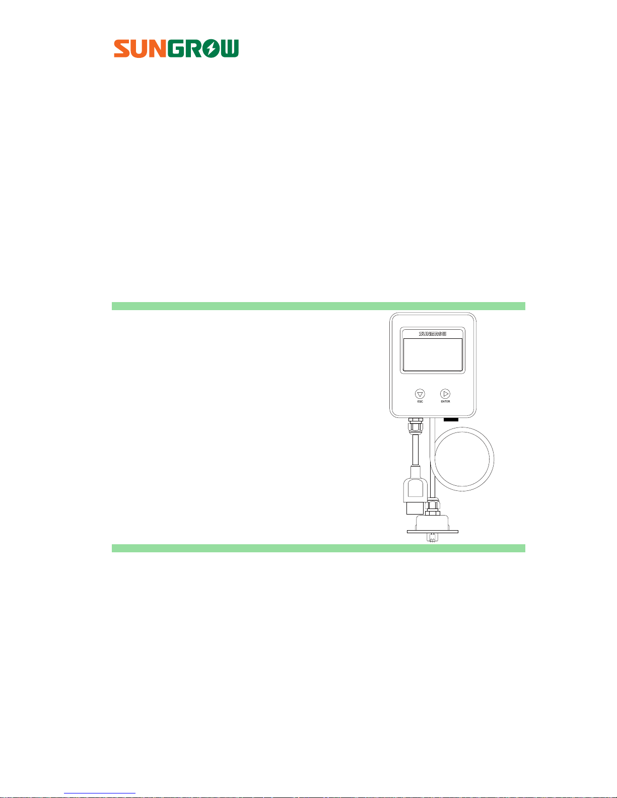
User Manual
eShow
LCD module
Page 2

Page 3

I
Contents
1 InstallationandConnection ................................................ 1
1.1 Connecting the eShow to the Inverter .......................................................... 1
1.2 Connecting the eShow to the DRED ............................................................... 2
2 LCD Operation .......................................................................... 5
2.1 Description of Button Function ........................................................................ 5
2.2 Menu Tree ................................................................................................................. 6
2.3 Main Screen ............................................................................................................. 7
2.4 Contrast Adjustment ............................................................................................. 8
2.5 Checking Running Information ........................................................................ 9
2.6 Setting the Country Code ................................................................................ 10
2.7 Setting the Time .................................................................................................. 11
2.8 Starting/Stopping the Inverter ...................................................................... 11
2.9 Setting the Running Parameters ................................................................... 12
2.10 Settings ................................................................................................................... 14
2.10.1 Password Entry ..................................................................................................... 14
2.10.2 Setting the Protective Parameters ................................................................ 14
2.10.3 GND Detection ..................................................................................................... 15
2.10.4 Total Energy Deviation Adjustment .............................................................. 15
2.10.5 Load Default .......................................................................................................... 16
2.10.6 Setting the Power Derating Parameters ..................................................... 16
2.10.7 Setting Other Parameters ................................................................................. 17
2.11 Setting the Communication Parameters .................................................... 17
2.12 Viewing Fault Records ....................................................................................... 18
3 Appendix ................................................................................ 19
3.1 Troubleshooting .................................................................................................. 19
3.2 Exclusion of Liability .......................................................................................... 24
3.3 About Us ................................................................................................................ 25
Page 4

Page 5
1
1 InstallationandConnection
1.1 Connecting the eShow to the Inverter
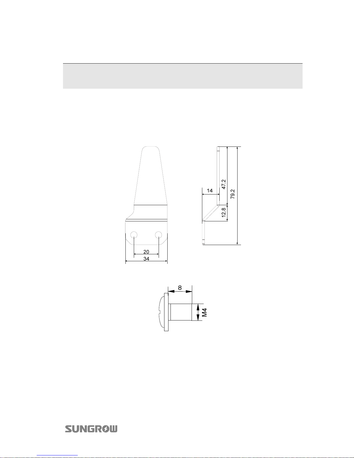
The eShow is installed onto the inverter by means of the bracket and the M4 screw
in the packaging.
Fig. 1-1 Dimensions of the Bracket (unit: mm)
Fig. 1-2 Dimensions of the Fastener (unit: mm)
Page 6
1 InstallationandConnection User Manual
2
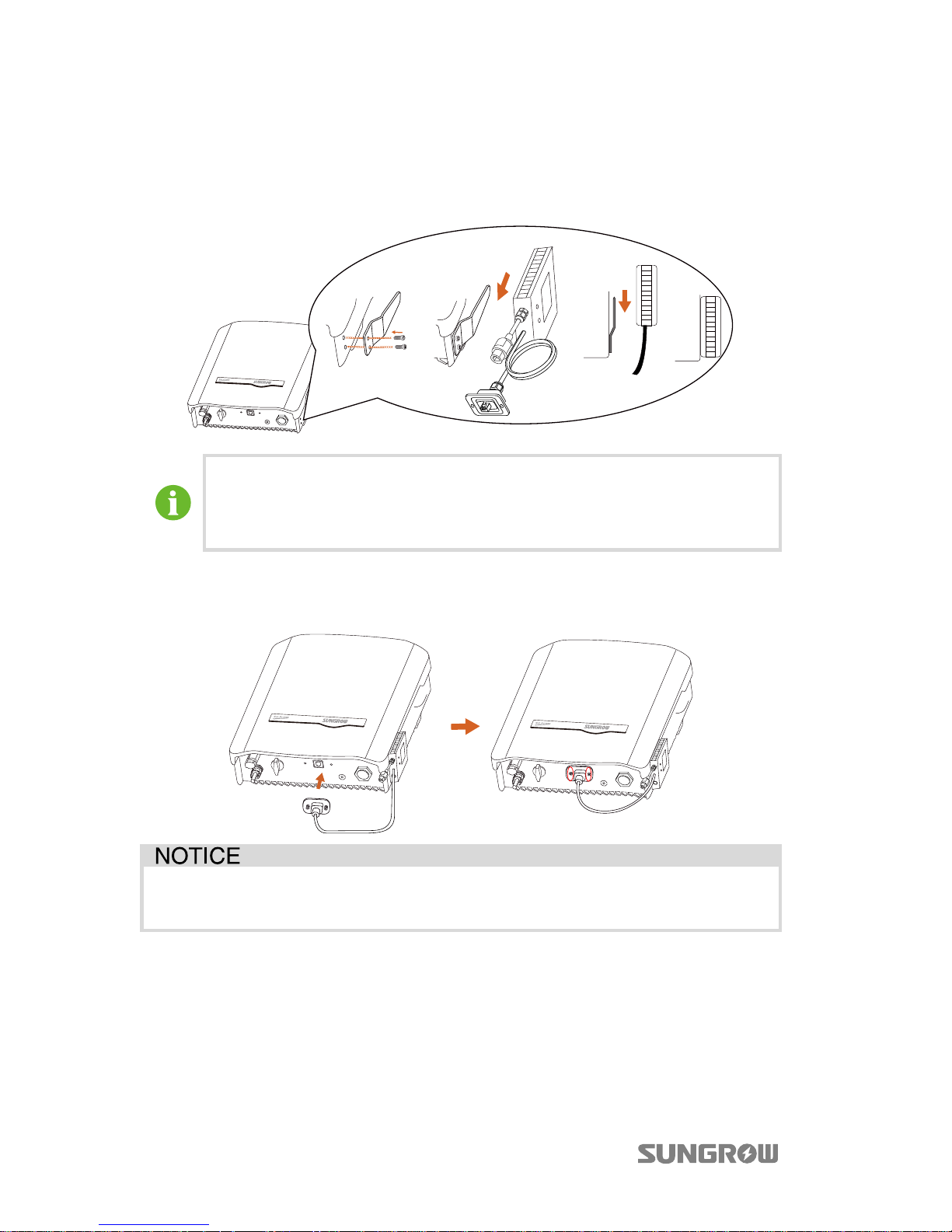
Procedure
Step 1 Secure the bracket to the inverter with the supplied screws and then hang
the eShow onto the bracket.
The eShow can also be mounted to the wall next to the inverter.
Make sure that the space between the eShow and the inverter is proper
for the cable connection.
Step 2 Connect the RJ45 plug to the RJ45 port on the bottom of the inverter. Fasten
the screws on the RJ45 plug.
Do not extend the communication cable. The loss of any or all rights may
follow if otherwise.
1.2 Connecting the eShow to the DRED
The eShow provides a DRM (Demand Response Mode) port for connecting to a
demand response enabling device (DRED). The DRM port is a standard Ethernet
port.
Page 7
User Manual 1 InstallationandConnection
3
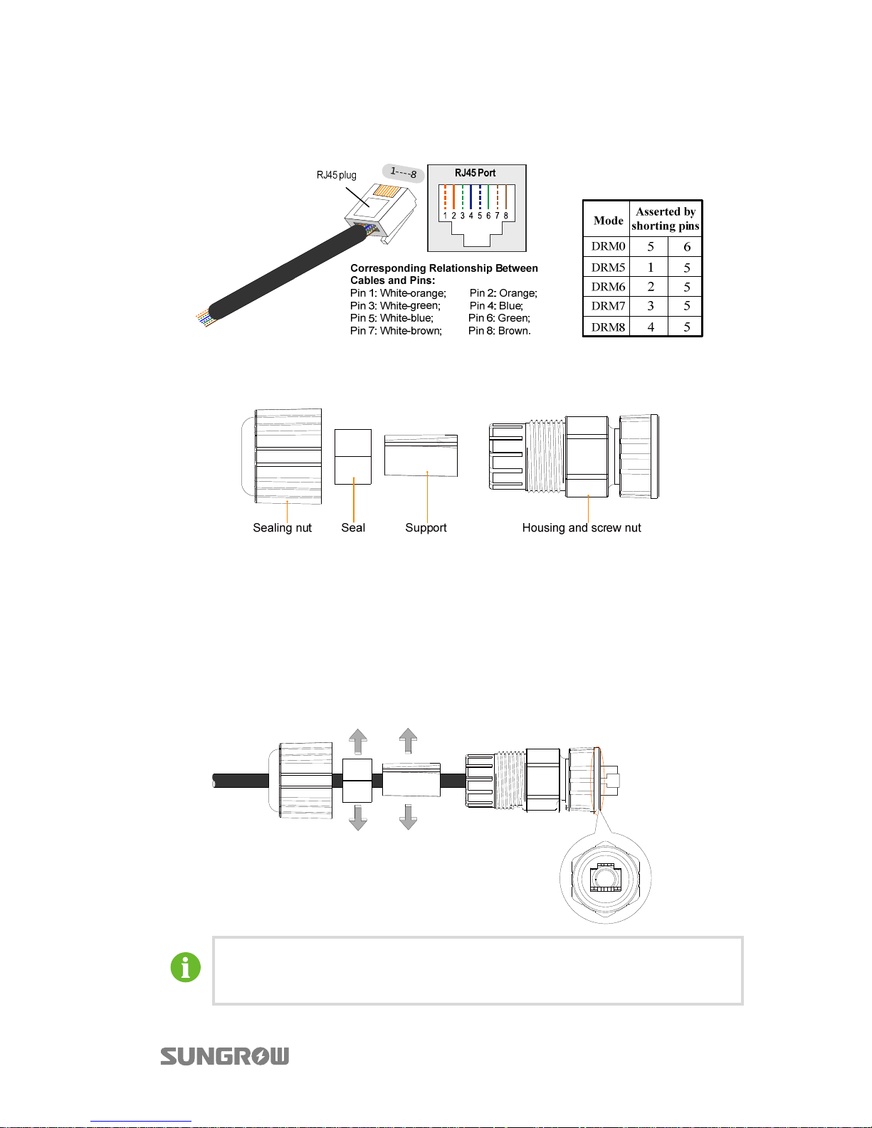
The following figure shows the DRM mode and the corresponding shorting pins of
the RJ45 plug.
The components of the DRM connector are included in the delivery scope, as shown
in the following figure.
Fig. 1-3 DRM Connector Components
* The seal and the support are not closed. So, you can use the standard network
cable with the RJ45 plug to assemble the DRM connector.
Procedure
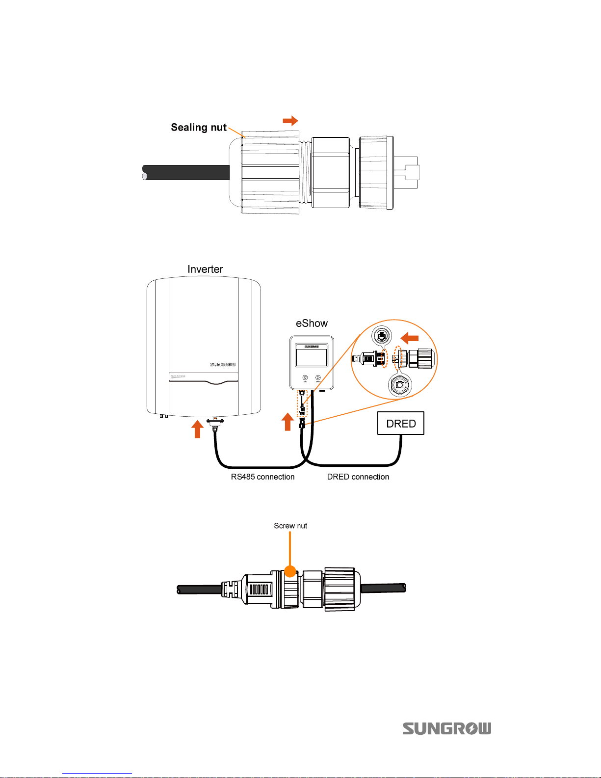
Step 1 Lead the network cable through the components according to the following
sequence.
The seal and the support can be opened to place the cable body.
Align the RJ45 plug and the slot to lead the cable through the housing.
Page 8
1 InstallationandConnection User Manual
4
Step 2
Push the support and the seal into the housing. Then tighten the sealing nut
to the housing.
Step 3 Align the DRM connector and the DRM terminal on the eShow. Plug the
connector and make them engage perfectly.
Step 4 Tighten the screw nut of the connector to the DRM terminal.
Page 9
5
2 LCD Operation
2.1 Description of Button Function
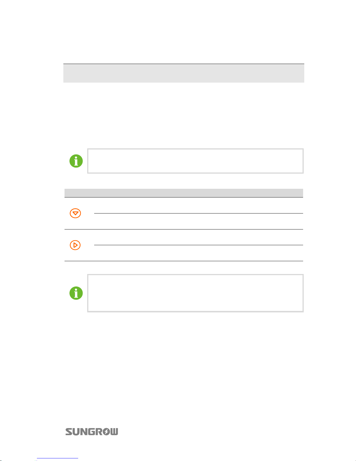
Inverter offers two buttons for users to look up the running information and
configure parameters. The two buttons have multiple functions. Please refer to Tab.
2-1 before any operation of the inverter.
Please wait about 15s for eShow startup after completing the
connection.
Tab. 2-1 Button function
Button Operation Description
≤2 s
Move upwards or downwards or scroll among set values.
Hereinafter, it is referred to as “Touch”.
>2 s
Return to a previous menu or cancel the settings.
Hereinafter, it is referred to as “Press ”.
≤2 s
Move left or right, or turn pages.
Hereinafter, it is referred to as “Touch ”.
>2 s
Enter the sub-menu or confirm the settings.
Hereinafter, it is referred to as “Press ”.
If there is no button operation for:
1 minute, LCD backlight will be automatically deactivated;
2 minutes, system will return to the default menu (main screen).
Page 10
2 LCD Operation User Manual
6
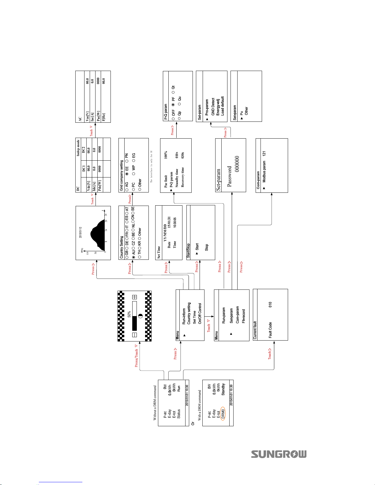
2.2 Menu Tree
Fig. 2-1 Menu tree
Page 11
User Manual 2 LCD Operation
7
2.3 Main Screen
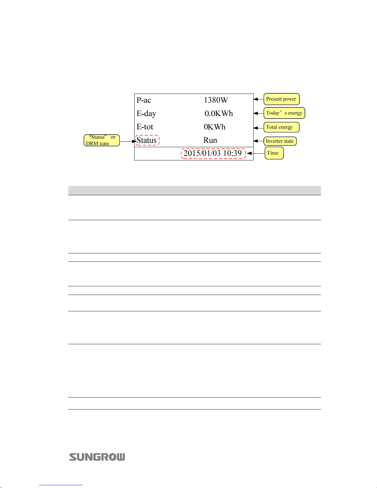
The LCD display will enter the main screen after successful commissioning, as shown
in Fig. 2-2.
Fig. 2-2 Main screen
Tab. 2-2 Description of the main screen
Status Description
Run
After being energized, inverter tracks the PV arrays’ maximum power
point (MPP) and converts the DC power into AC power. This is the
normal operation mode.
Standby
Inverter enters Standby mode when DC input is insufficient or with the
DRM0 command from the DRED. In this mode inverter will wait within
the Standby duration (set by user, refer to “2.9 Setting the Running
Parameters”).
Stop Inverter is stopped.
Key-stop
Inverter will stop running by manual “stop” via the LCD menu. In this
way, inverter internal DSP stops. To restart the inverter, manually start
via the LCD menu.
Startup The inverter is initializing and synchronizing with the grid.
Dispatch
Inverter output power can be adjusted via the LCD menu. The value of
Pac limit is lower than 100%.
Derating
Output derating is a way to protect the inverter form overload or
potential faults.
Situations require inverter power derating are too high internal
temperature, too low grid voltage and so on.
Fault ххх
If a fault occurs, inverter will automatically stop running, disconnect the
AC relay, and display the fault information on the LCD display with the
“FAULT” indicator on. “ххх” is the fault code, e.g. “010”.
Once the fault is removed in recovery time (set by user, refer to “2.9
Setting the Running Parameters”), inverter will automatically resume
running.
Warn ххх Warning information is detected. “ххх” is the warning code, e.g. “070”.
Page 12
2 LCD Operation User Manual
8
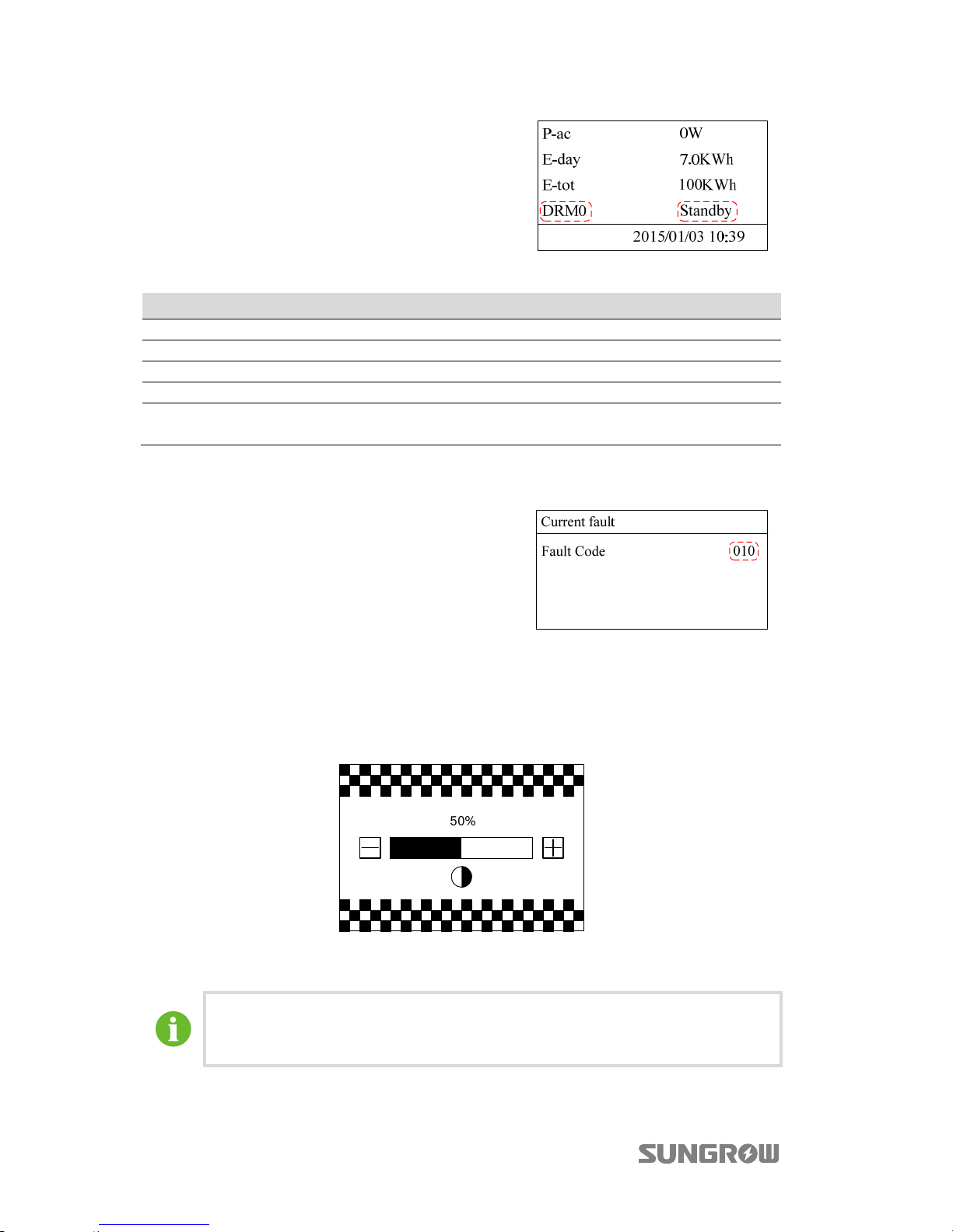
If a DRED is connected to the eShow and the
DRED activates a DRM command, the DRM
state will be shown on the main screen, as
shown in the figure.
Tab. 2-3 Demand Response Modes (DRMs)
Mode Explanation
DRM0 The inverter is in the state of standby.
DRM5 The export power to the grid is 0%.
DRM6 The export power to the grid is no more than 50% of the rated power.
DRM7 The export power to the grid is no more than 75% of the rated power.
DRM8
The export power to the grid is 100%, but subject to the constraints from
other active DRMs.
Viewing Current Fault
If inverter is in “Fault”state, touch to
view “Current fault” information. To know
the meaning of the fault code, please
refer to “3.1 Troubleshooting”.
2.4 Contrast Adjustment
Step 1 Press/touch on the main screen to enter the contrast adjustment screen.
Step 2 To uc h to increase the setting value and touch to decrease the value.
Step 3 Press to confirm the contrast setting.
Contrast adjustment range: 0…100%
Recommended value: 50% or 60%.
Page 13
User Manual 2 LCD Operation
9
2.5 Checking Running Information
The main screen displays some basic information about the inverter. For more
detailed information, please operate as follows:
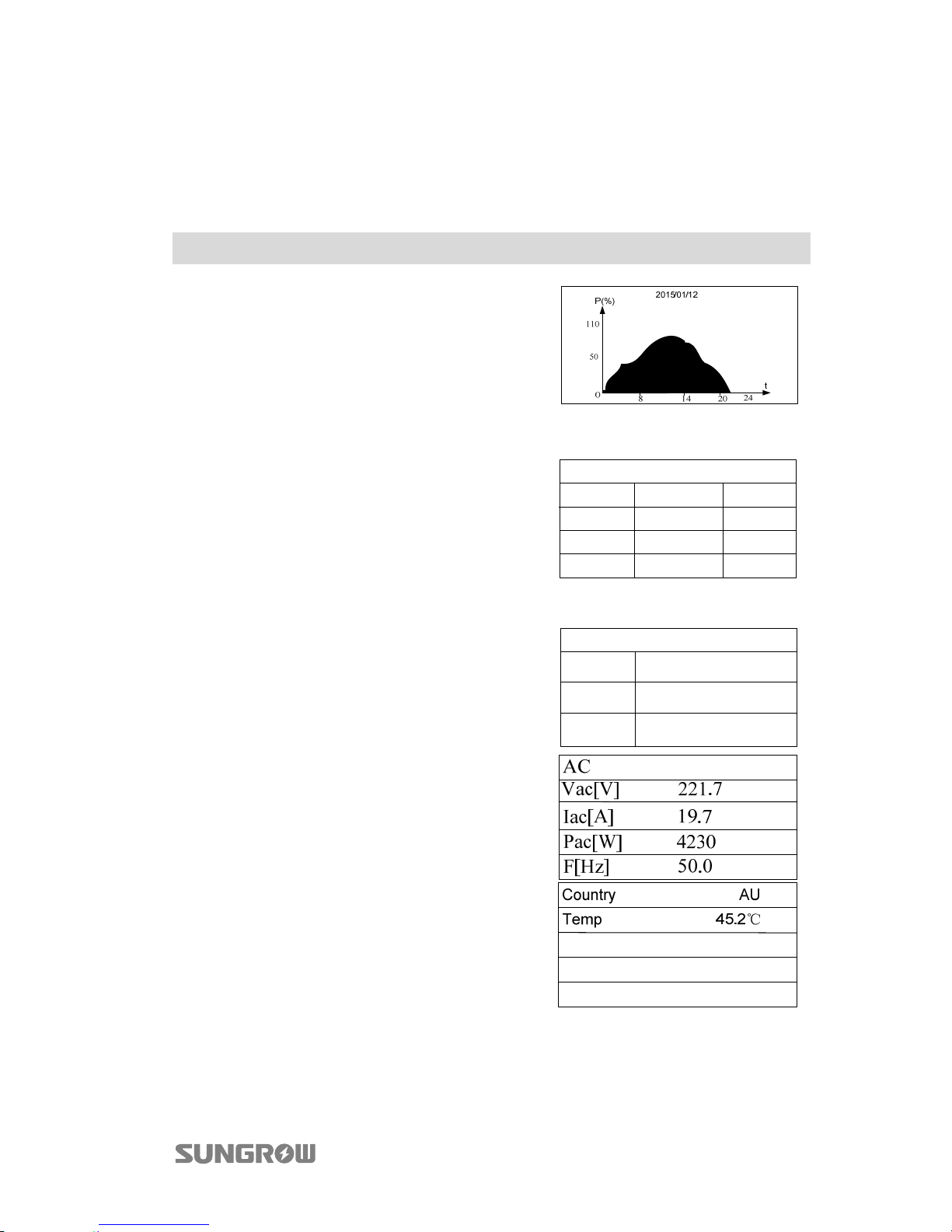
Main Screen (Press )→Menu→Run-inform (Press )
Scroll pages by touching .
T
he power curve shows the daily power
output. Each point in the curve is the
percentage of the present power to the
nominal power.
If the inverter has two pairs of DC terminals, the DC information will be as shown in
the figure.
Vdc[V]: DC voltage of each input.
Idc[A]: DC current of each input.
Pdc[W]: DC power of each input.
Indep mode/Paral mode:
The PV configuration mode of the two PV
inputs. Refer to "5.5.1 PV Inputs
Configuration" in the User Manual of inverter.
DC Paral mode
Pdc[W] 2142 2177
Idc[A] 6.2 6.3
Vdc[V] 345.6 345.6
DC1 DC2
If the inverter has a pair of DC terminals, the DC
information will be as shown in the figure.
Vdc[V]: DC voltage.
Idc[A]: DC current.
Pdc[W]: DC power.
DC
Pdc[W] 0000
Idc[A] 0.0
Vdc[V] 00.0
Vac[V]: AC output voltage.
Iac[A]: AC output current.
Pac[W]: AC output power.
F[Hz]: Frequency of AC output.
Country: Country code.
Temp: The internal temperature of the inverter.
Page 14
2 LCD Operation User Manual
10
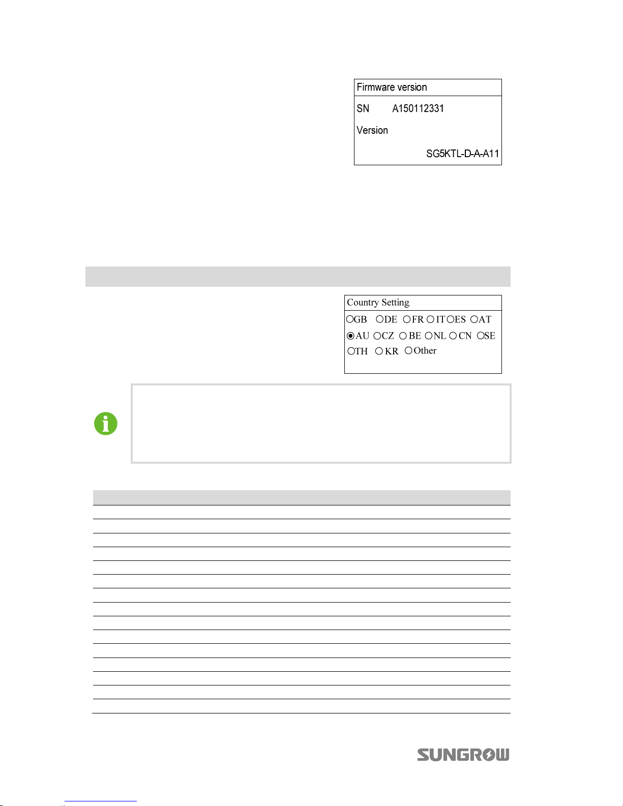
Inverter shows detailed device information,
including the SN and the firmware version.
The firmware version information is read only.
2.6 Setting the Country Code
To make the protection parameters setting convenient, inverter provides in-built
protection parameters for certain countries.
Main Screen (Press )→Menu (Touch ×1)→Country setting (Press )
Touch / to choose countries and press to
confirm.
If the country selected is not in the list, please
choose Other and then input the protection
parameters manually.
Tab. 2-4 Country code description
Country Code Country Language
GB Great Britain English
DE Germany German
FR France French
IT Italy Italian
ES Spain English
AT Austria German
AU Australia English
CZ Czech English
BE Belgium French
NL Netherlands English
CN China Chinese
SE Sweden English
TH Thailand English
KR Korea Korean
Other Country not mentioned above English
After setting the Country, please set other parameters of the inverter in
accordance with the specific requirements of the local grid. Check the
parameters thoroughly before commissioning.
SUNGROW assumes no liability for direct or indirect damage arising from
the parameters exceeding the permissible range of the utility grid.
Page 15
User Manual 2 LCD Operation
11
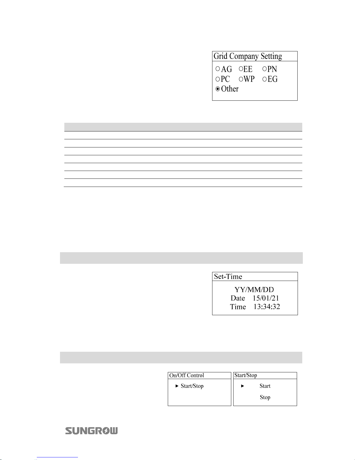
If the country code is set to AU, the grid
company setting will appear. Touch / to
choose grid code and press to confirm.
Tab. 2-5 Grid company code description
Grid company Code Company
AG AusGrid, NSW
EE Ergon Energy, QLD
PN SA Power Networks,SA
PC Powercor,VIC
WP Western Power,WA
EG Energex, QLD
Other Company not mentioned above
2.7 Setting the Time
The correct system time is very important. If there is deviation between the system
time and the local time, the inverter will not operate normally. The clock is in
24-hour format. Proceed as follows to set the correct time.
Main Screen (Press )→Menu (Touch ×2)→Set Time(Press )
Touch to move the cursor and touch to
change value. Press to confirm setting.
2.8 Starting/Stopping the Inverter
Main Screen (Press )→Menu (Touch ×3)→On/Off Control (Press )
Touch to choose and press
to confirm the choice.
Press to confirm.
Page 16
2 LCD Operation User Manual
12
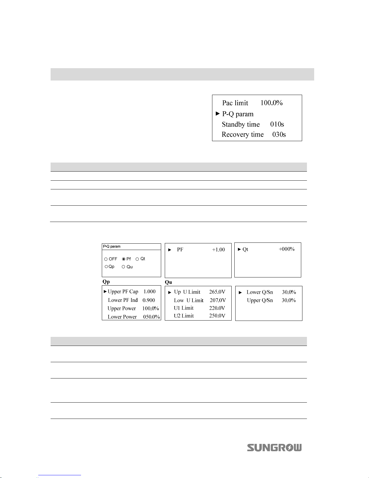
2.9 Setting the Running Parameters
Main Screen (Press )→Menu (Touch ×4)→Run-param (Press )
On the “Run-param” screen, touch to select one
item and press to enter the setting interface.
For each item, touch to move the cursor and
touch to set the appropriate value.
Confirm settings by pressing .
Tab. 2-6 Description of Running Parameters
Parameter Description Default Range
Pac limit Inverter active power limitation 100.0% 0~100%
P-Q param Power factor param - -
Standby time
Time from inverter standby to
startup
10s 20~255s
Recovery time
Time from inverter fault is
removed to standby
30s
[IT: 300s]
0-900s
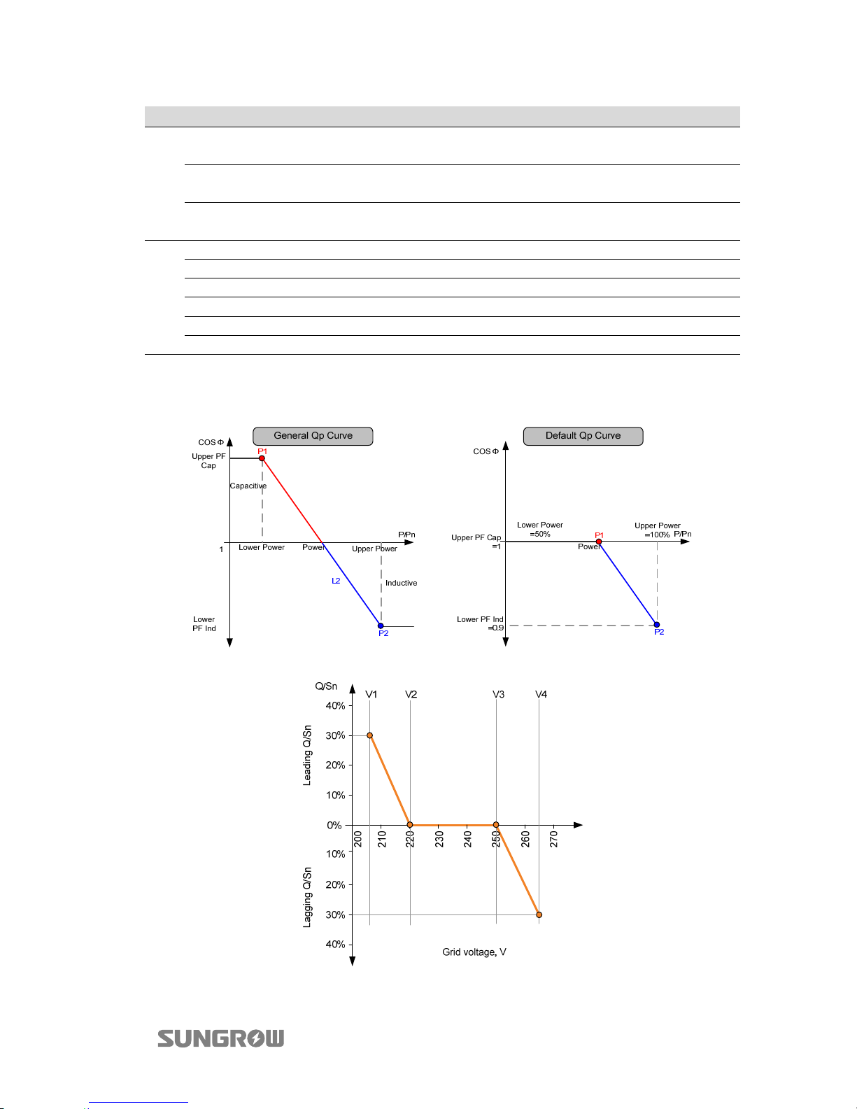
Select P-Q param and touch to select the mode. Press to enter the submenu.
Tab. 2-7 Description of P-Q param
Parameter Description Default Range
OFF
Disable the function of
reactive power regulating.
- -
PF Inverter output power factor +1.000
-1.000~-0.800/
+0.800~+1.000
Qt
The maximum ratio of reactive
power to rated apparent
power as %.
-060%...+060%
Qp Upper PF Cap
Power factor of point P1 in the
Qp mode curve
1.000 0.9…1
Page 17
User Manual 2 LCD Operation
13
Parameter Description Default Range
Lower PF Ind
Power factor of point P2 in the
Qp mode curve
0.900 0.9…1
Upper Power*
Output power of point P2 in
the Qp mode curve (in %)
100.0% 50%...100%
Lower Power*
Output power of point P1 in
the Qp mode curve (in %)
050.0% 0%...50%
Qu
Up U Limit Grid voltage reference value 4 265.0 V 244 V...265 V
Low U Limit Grid voltage reference value 1 207.0 V U1 Limit Grid voltage reference value 2 220.0 V 216 V... 230 V
U2 Limit Grid voltage reference value 3 250.0 V 235 V... 255 V
Upper Q/Sn Q/Sn value of voltage V1 30.0% 0%...60%
Lower Q/Sn Q/Sn value of voltage V4 30.0% 0%...60%
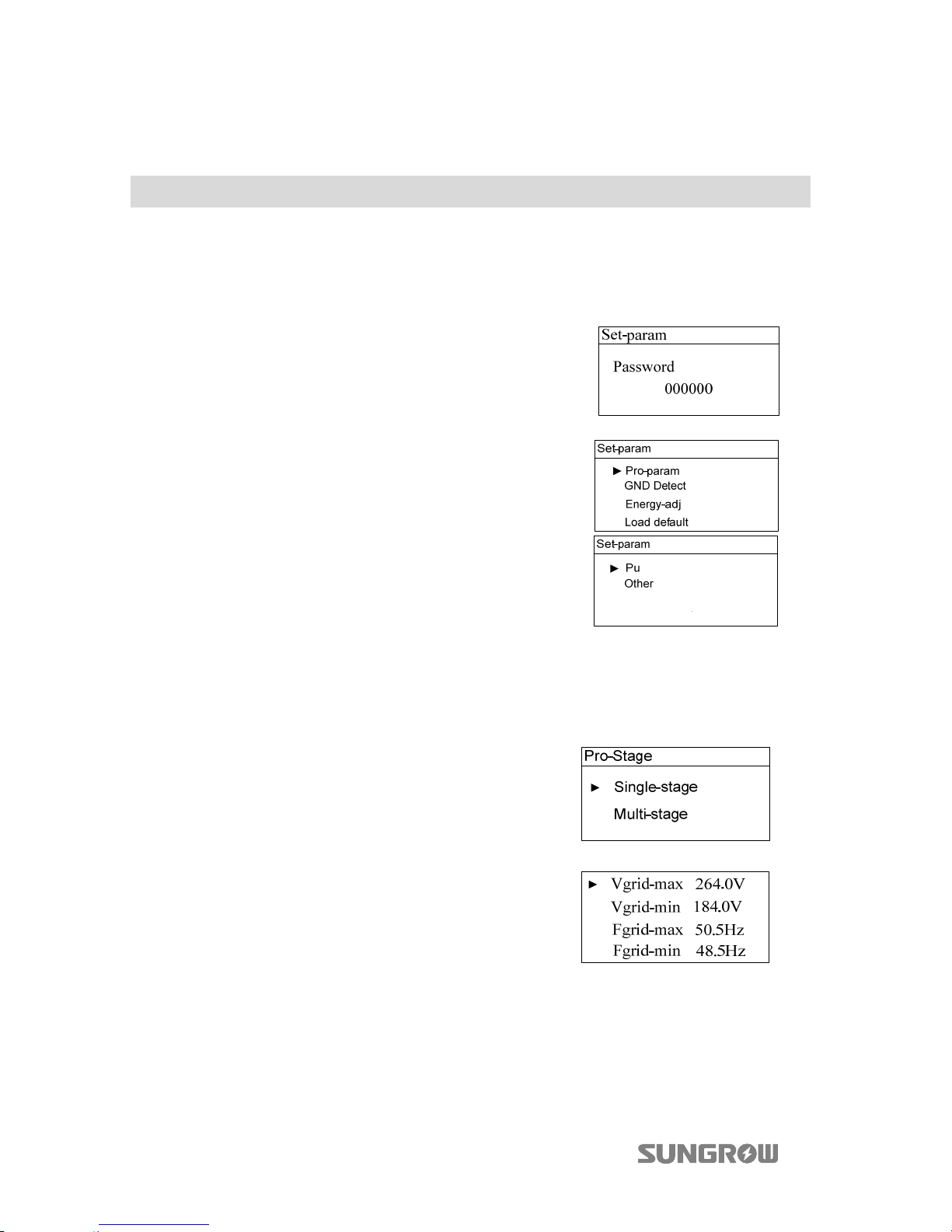
*Lower Power <Upper Power
“
+”: the current leads the voltage, ”-”: the current lags the voltage”
Fig. 2-3 Reactive Power Regulation Curve in Q(p) Mode
Fig. 2-4 Reactive Power Regulation Curve in Q(U) Mode
Page 18
2 LCD Operation User Manual
14
2.10 Settings
Main Screen (Press )→Menu (Touch ×5)→Set-param (Press )
2.10.1 Password Entry
Set-parameter setting is password-protected. To set the parameters, you should
input the correct password.
Step 1 A password confirmation screen will occur.
To uc h to move cursor right and touch
to inpu t the passw o rd 111111.
Step 2 Press to confirm the password and enter
the “Set-param” submenu.
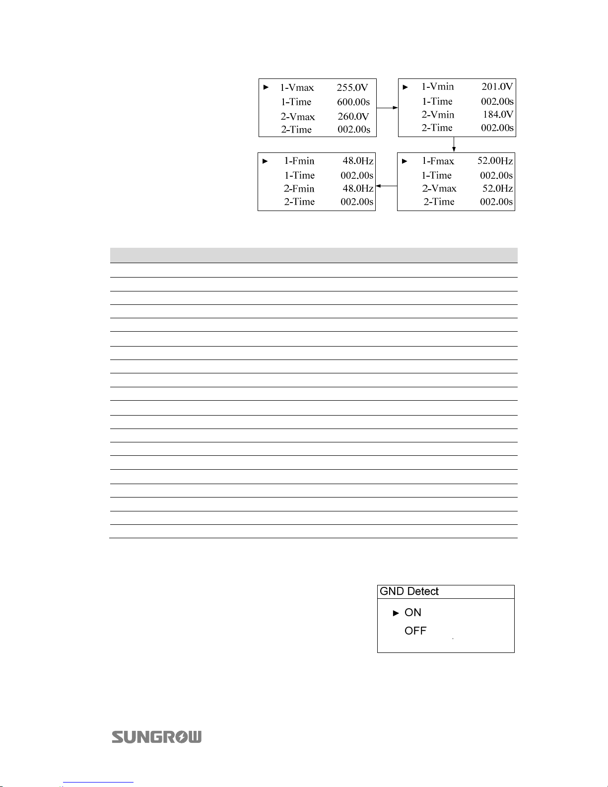
2.10.2 Setting the Protective Parameters
Protective parameters are designed for the threshold values that can trigger the
protection function of the inverter.
T
he single-stage and multi-stage protection
parameter setting interface will appear.
Single-stage Protection Parameter Setting:
Touch to select parameter, touch to move the
cursor and touch to set the appropriate value.
Confirm settings by pressing .
Page 19
User Manual 2 LCD Operation
15
Multi-stage Protection
Parameter Setting:
To uc h to select
parameter, touch to
move cursor and touch
to set the appropriate
value. Confirm settings
by pressing .
Tab. 2-8 Multi-stage Protection Parameters Explanation
Parameter Explanation
Max-V. prot
Over-voltage protection
1-Vmax Stage 1 Grid over-voltage (U>)
1-Time Stage 1 Grid over-voltage (U>) tripping time
2-Vmax Stage 2 Grid over-voltage (U>>)
2-Time Stage 2 Grid over-voltage (U>>) tripping time
Min-V. prot
Under-voltage protection
1-Vmin Stage 1 Grid under-voltage (U<)
1-Time Stage 1 Grid under-voltage (U<) tripping time
2- Vmin Stage 2 Grid under–voltage (U<<)
2-Time Stage 2 Grid under–voltage (U<<) tripping time
Max-F. prot
Over-frequency protection
1- Fmax Stage 1 Grid over-frequency (f>)
1- Time Stage 1 Grid over-frequency (f>) tripping time
2- Fmax Stage 2 Grid over-frequency (f>>)
2- Time Stage 2 Grid over-frequency (f>>) tripping time
Min-F. prot
Under-frequency protection
1- Fmin Stage 1Grid under-frequency (f<)
1- Time Stage 1 Grid under-frequency (f<) tripping time
2- Fmin Stage 2 Grid under-frequency (f<<)
2- Time Stage 2 Grid under-frequency (f<<) tripping time
2.10.3 GND Detection
To uc h to select ON/Off and confirm settings by
pressing .
Select ON to enable the GND Detect function.
When the enclosure of the inverter is not grounded, the code 106 will be shown on the
main screen and the buzzer inside will sound at the same time.
Page 20
2 LCD Operation User Manual
16
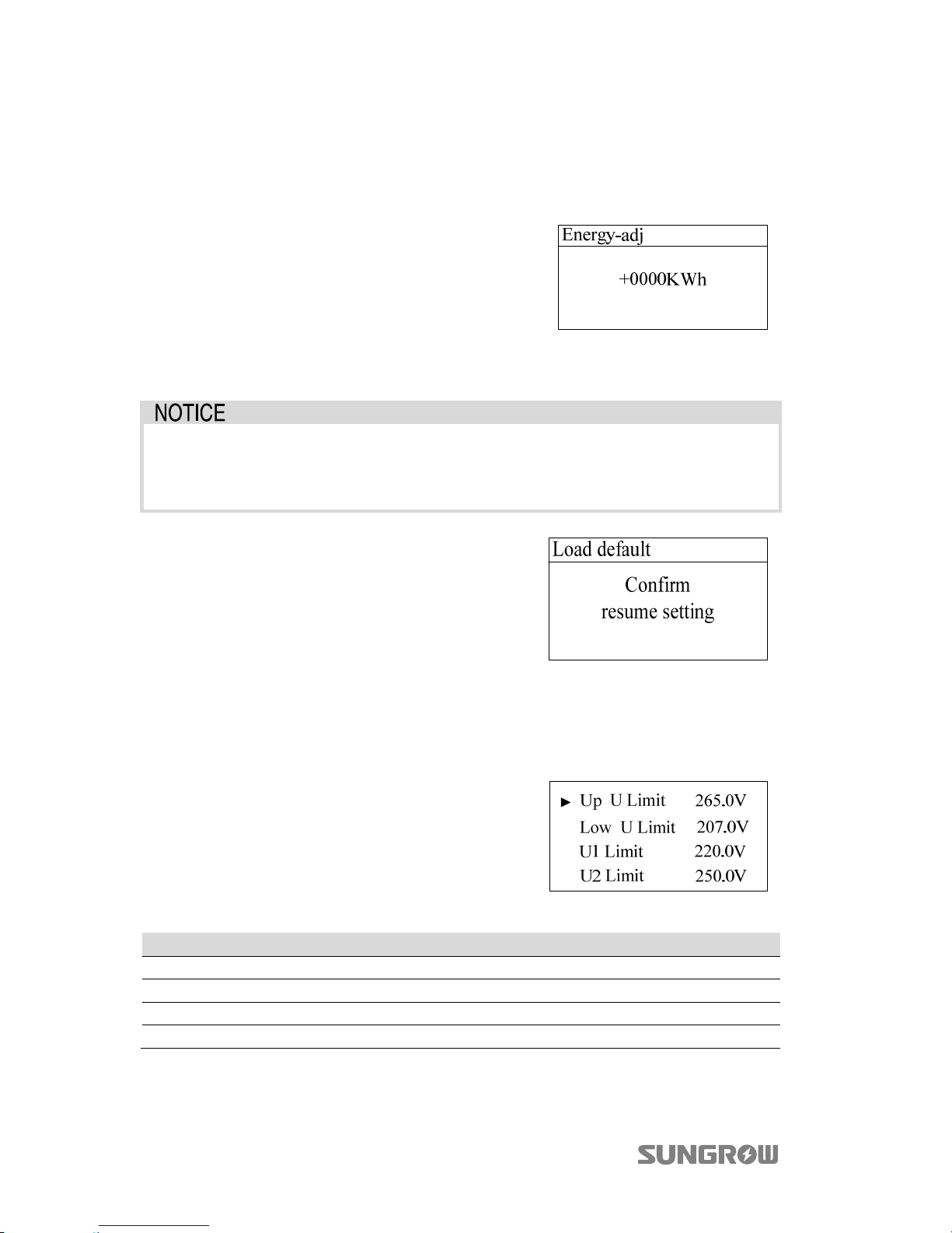
2.10.4 Total Energy Deviation Adjustment
If the accumulative value “E-total” in the inverter is different from the value in the
external metering device, you should adjust energy by “Energy-adj” setting.
Touch to move the cursor and touch to
change the value. Press to confirm the setting.
The “+” can be changed to “-”.
The adjustment rangs from -9999 to +9999 kWh.
(Energy-adj value)=(Real measured value) - (E-tot
reading value).
2.10.5 Load Default
All history information will be unrecoverable and all parameters will return
to the default value except the protective parameters and time once the
“load default” operation is performed.
Press to confirm “load default”.
2.10.6 Setting the Power Derating Parameters
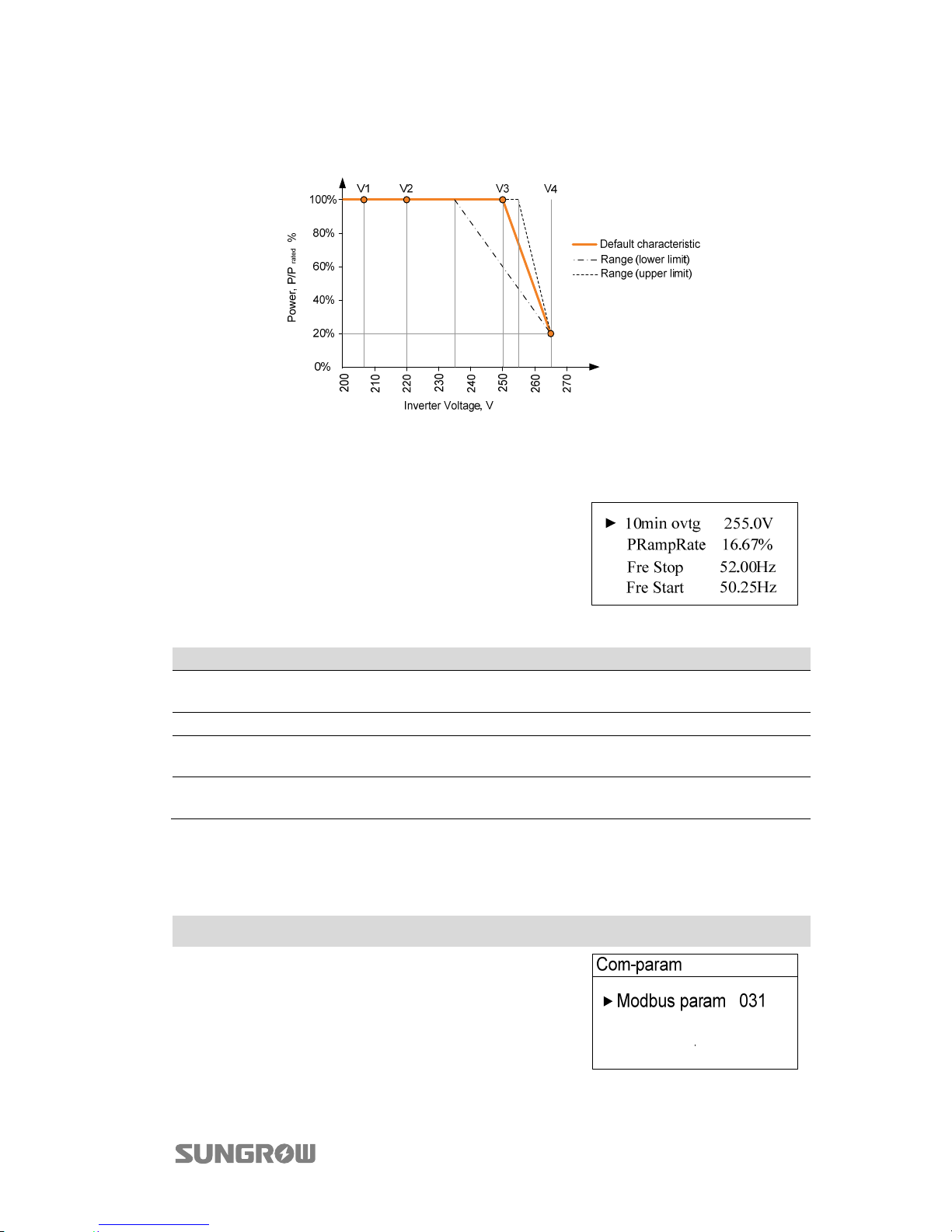
Set four grid voltage reference values. The output power of the inverter varies in
response to the grid voltage.
Touch to move the cursor and touch to
change value. Press to confirm setting.
Tab. 2-9 Description of Power Derating Parameters
Parameter Description Default Range
Up U Limit Grid voltage reference value 4 265.0 V 244 V...265 V
Low U Limit Grid voltage reference value 1 207.0 V U1 Limit Grid voltage reference value 2 220.0 V 216 V... 230 V
U2 Limit Grid voltage reference value 3 250.0 V 235 V... 255 V
Page 21
User Manual 2 LCD Operation
17
The response curve is defined by the voltage reference values and corresponding
power levels.
Fig. 2-5 Power Response Curve in P(u) Mode
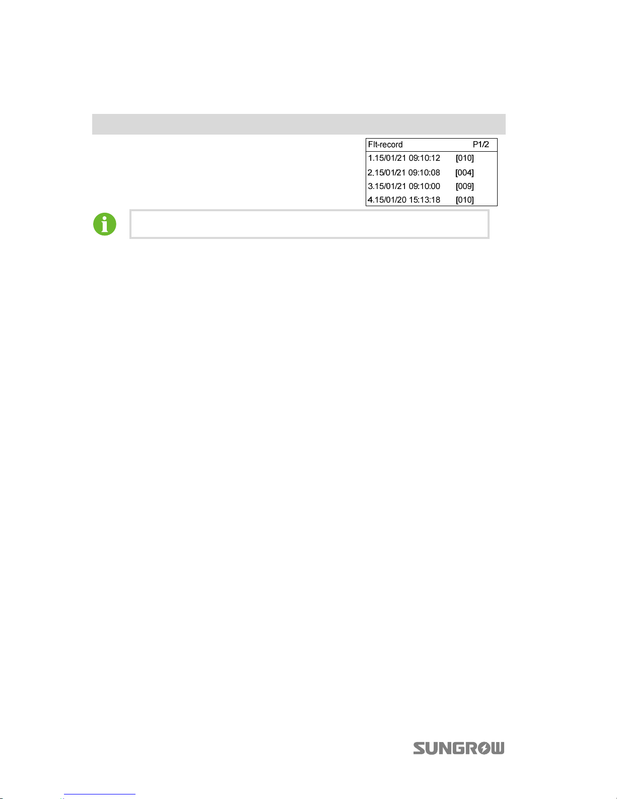
2.10.7 Setting Other Parameters
Touch to move the cursor and touch to
change value. Press to confirm setting.
Tab. 2-10 Description of Other Parameters
Parameter Description Default Range
10min ovtg
10-minute overvoltage protective
value
255.0 V 244 V...258 V
PRampRate The ramp rate of power variation 16.67% 5% ~100%
Fre Stop
The Stop frequency value for
over-frequency derating
52.00 Hz 51.00Hz...52.00Hz
Fre Start
The Start frequency value for
over-frequency derating
50.25 Hz 50.25Hz...52.00Hz
2.11 Setting the Communication Parameters
Main Screen (Press )→Menu (Touch ×6)→Com-param (Press )
Touch to move the cursor and touch to set the
appropriate value. Confirm settings by pressing .
Device address range: 1-247.
Page 22
2 LCD Operation User Manual
18
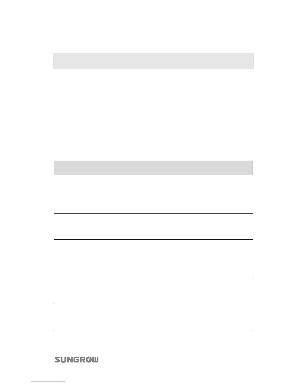
2.12 Viewing Fault Records
Main Screen (Press )→Menu (Touch ×7)→Flt-record (Press )
Inverter shows fault record pages.
Scroll pages by touching .
The inverter can only store at most 20 latest fault records.
Page 23
19
3 Appendix
3.1 Troubleshooting
When the data on the screen of eShow cannot be refreshed on time, please follow
the procedure below for a solution.
Step 1 Disconnect the external AC circuit breaker firstly.
Step 2 Turn off the upstream DC circuit break or pull off the MC4 terminal.
Step 3 check whether the communication cable of the eShow is firmly connected
Step 4 If the fault still exists, contact Sungrow Service Dept.
When faults occur, the “Fault” state will be shown on the main screen.
Fault
Code
Description Troubleshooting
002
The grid voltage exceeds
the inverter allowable
upper limit.
1. Check the voltage of the grid.
2. If the grid voltage exceeds the permissible
range of inverter protection parameters, ask
the local utility grid authority for solution.
3. If the grid voltage is within the permissible
range, contact Sungrow Service Dept.
003
Grid transient voltage
exceeds the permissible
range
1. This is a short-term fault due to grid
condition. Wait a moment for inverter recovery.
2. If the fault still exists, please contact
Sungrow Service Dept.
004
The grid voltage is below
inverter’s allowable lower
limit.
1. Check the grid voltage.
2. If the grid voltage exceeds the permissible
range of inverter protection parameters, ask
utility grid company for solution.
3. If the grid voltage is within the permissible
range, contact Sungrow Service Dept.
005
The grid voltage is too
low.
1. This is a short-term fault due to grid
condition. Wait a moment for inverter recovery.
2. If the fault still exists, please contact
Sungrow Service Dept.
006
The AC output current
exceeds inverter
allowable upper limit.
1. The inverter will resume if the output current
falls below the protection value.
2. If the fault still exists, please contact
Sungrow Service Dept.
Page 24
3 Appendix User Manual
20
Fault
Code
Description Troubleshooting
007 Transient AC overcurrent
1. The inverter will self-recover after several
seconds.
2. If the fault still exists, please contact
Sungrow Service Dept.
008
The grid frequency
exceeds inverter
allowable upper limit.
1. Check the grid frequency.
2. If the grid frequency exceeds the permissible
range of inverter protection parameters, ask
utility grid company for solution.
3. If the grid frequency is within the permissible
range, contact Sungrow Service Dept.
009
The grid frequency is
below the inverter
allowable lower limit.
010 Islanding
1. Check whether AC circuit breaker is
triggered.
2. Check whether AC cables are all firmly
connected.
3. Check whether grid is not in service.
4. If all conditions are OK and this fault still
occurs in the LCD screen, contact Sungrow
Service Dept.
011
The DC component of AC
current exceeds inverter
limit.
1. Wait a moment for inverter recovery.
2. If the fault occurs repeatedly, contact
Sungrow Service Dept.
012
A failure current is
detected.
1. Check the PV strings for ground fault.
2. If the fault occurs repeatedly, contact
Sungrow Service Dept.
014
The average grid voltage
exceeds the permissible
range for over 10
minutes.
1. Check whether the inverter selected country
code is the country you are in.
2. Wait a moment for inverter recovery.
3. Check the voltage of the grid. If the grid
voltage exceeds the permissible range of
inverter protection parameters, ask utility grid
company for solution.
4. If the fault occurs repeatedly, contact
Sungrow Service Dept..
015
The grid voltage exceeds
the permissible range
1. Check the model of the AC cables.
2. Wait a moment for inverter recovery.
3. If the grid voltage exceeds the permissible
range, ask utility grid company for solution.
4. If the fault occurs repeatedly, contact
Sungrow Service Dept.
016
The bus voltage or power
is high.
1. Wait a moment for inverter recovery.
2. If the fault occurs repeatedly, contact
Sungrow Service Dept.
019
The transient bus voltage
is high.
1. Wait a moment for inverter recovery.
2. If the fault occurs repeatedly, contact
Sungrow Service Dept.
Page 25
User Manual 3 Appendix
21
Fault
Code
Description Troubleshooting
020 The bus voltage is high.
1. Wait a moment for inverter recovery.
2. If the fault occurs repeatedly, contact
Sungrow Service Dept.
021
PV1 input overcurrent is
detected
Check the layout and the wiring of PV1 input.
022
PV2 input overcurrent is
detected
Check the layout and the wiring of PV2 input.
036
The temperature of
radiator is too high
1. Check whether the placement of inverter is
correctly.
2. Check whether the inverter operating
ambient temperature is more than the range
indicated in the specification.
3. Check whether AC output power exceeds
the nominal power.
4. If the fault still exists, please contact
Sungrow.
037
The internal temperature
of inverter is too high
038 Relay fault is detected
1. Wait a moment for inverter recovery.
2. If the fault occurs repeatedly, contact
Sungrow Service Dept.
039
The insulation resistance
is low. (ISO-flt)
1. Check whether there is a reliable inverter
grounding line.
2. Check whether the positive and negative of
PV panels is short-circuited with ground lead.
3. Wait a moment for inverter recovery.
4. If the fault occurs repeatedly, contact
Sungrow Service Dept.
041
Leakage current self-test
abnormality
1. Wait a moment for inverter recovery.
2. If the fault occurs repeatedly, contact
Sungrow Service Dept.
047
Two PV inputs are
connected and their
configurations are
different. (Only for
SG4KTL-S)
1. Rotate the DC switch to OFF and disconnect
the PV connections.
2. Check and ensure that the two PV inputs are
of the same configurations in PV module types,
numbers of PV panels, tilt angles and
orientation angles.
3. Measure the open-circuit voltages to check if
they are the same.
048 Sampling channel failure
1. Wait a moment for inverter recovery.
2. If the fault occurs repeatedly, contact
Sungrow Service Dept.
Page 26
3 Appendix User Manual
22
Fault
Code
Description Troubleshooting
053
Auxiliary DSP detects grid
voltage exceeds set
protection value
1. Check the grid voltage.
2. If the grid voltage exceeds the permissible
range of inverter protection parameters, ask
utility grid company for solution.
3. If the grid voltage is within the permissible
range, contact Sungrow Service Dept.
054
Auxiliary DSP detects grid
frequency exceeds set
protection value
1. Check the grid frequency.
2. If the grid frequency exceeds the permissible
range of inverter protection parameters, ask
utility grid company for solution.
3. If the grid frequency is within the permissible
range, contact Sungrow Service Dept.
056
Auxiliary DSP detects
leakage current exceeds
set protectino range
1. Check whether there is a grounded fault of
the PV string.
2. If the fault occurs repeatedly, contact
Sungrow Service Dept.
057
Auxiliary DSP AC current
sampling channel
anomaly
1. Wait a moment for inverter recovery.
2. If the fault occurs repeatedly, contact
Sungrow Service Dept.
058
Auxiliary DSP detects AC
current DC injection
exceeds inverter set
protection range
1. Wait a moment for inverter recovery.
2. If the fault occurs repeatedly, contact
Sungrow Service Dept.
059
Main and auxiliary DSP
communication anomaly
1. Wait a moment for inverter recovery.
2. If the fault occurs repeatedly, contact
Sungrow Service Dept..
060
Main and auxiliary DSP
sampling difference
1. Wait a moment for inverter recovery.
2. If the fault occurs repeatedly, contact
Sungrow Service Dept.
070 Fans are defective
Stop the inverter and disconnect the AC & DC
cables. Check whether the fan duct has been
blocked. If not, replace fans.
074
Communication fault of
LCD
1. Check whether communication cable of the
eShow is firmly connected.
2. If the communication cable is firmly
connected, a fault has occurred in the internal
communication of the inverter. However, the
inverter continues feeding into the grid.
Contact Sungrow Service Dept.
087
Arc self-detection
anomaly warn
Wait a while. Contact Sungrow if device is still
in self-detection warn state.
Page 27
User Manual 3 Appendix
23
Fault
Code
Description Troubleshooting
088 Arc anomaly fault
1. Stop the inverter and disconnect the AC &
DC cables. Check cable connection for aging
and looseness. Re-power on and remove the
arc warn manually.
2. Contact Sungrow if this fault still occurs.
089 Arc detection OFF warn
Remove the warn by enable arc detection
function or keep the warn by closing arc
detection function.
100
The AC output current
exceeds inverter
protection limit.
1. The inverter will resume if the output current
falls below the protection value.
2. If the fault still exists, please contact
Sungrow Service Dept.
101
The grid frequency
exceeds inverter
allowable upper limit.
1. Check the grid frequency.
2. If the grid frequency exceeds the permissible
range of inverter protection parameters, ask
utility grid company for solution.
3. If the grid frequency is within the permissible
range, contact Sungrow Service Dept.
102
The grid frequency is
below the inverter
allowable lower limit.
106
The inverter is not
grounded.
Neither the PE terminal
on the AC connection
block nor the second PE
terminal on the enclosure
is reliably connected.
Check whether there is a reliable inverter
grounding line.
If there is access to the ground, and the fault
still exists, please contact Sungrow Service
Dept.
200 The bus voltage is high.
1. Wait for inverter recovery after bus voltage
lower.
2. If the fault occurs repeatedly, contact
Sungrow Service Dept.
201
The bus voltage is too
low.
1. Wait a moment for inverter recovery.
2. If the fault occurs repeatedly, contact
Sungrow Service Dept.
202 PV current overcurrent
1. Wait for inverter recovery after DC current is
reduced.
2. If the fault occurs repeatedly, contact
Sungrow Service Dept.
205
AC output relay
abnormal
1. Wait a moment for inverter recovery.
2. If the fault occurs repeatedly, contact
Sungrow Service Dept.
307 DC power is too high
Check whether the configuration of PV is in the
range indicated in the specification. If the fault
occurs repeatedly, contact Sungrow Service
Dept.
Page 28

3 Appendix User Manual
24
3.2 Exclusion of Liability
The content of the document is periodically checked and revised when necessary.
Discrepancies therefore may exist. Readers are cautioned that Sungrow reserves the
right to make changes without notice. Please call us or visit our website at
www.sungrowpower.com for the latest information. No guarantee is made for the
completeness of the document. Please contact our company or distributors to get
the latest version.
Guarantee or liability claims for damage of any kind are excluded if they are caused
by one or more of the followings:
improper or inappropriate use or install of the product;
installing or operating the product in unintended environment;
installing or operating the product without observing relevant safety regulations
in the deployment location;
ignoring the safety warnings or instructions contained in all documents relevant
to the products;
installing or operating the products under incorrect safety or protection
conditions;
altering the products or supplied software without authority;
the product malfunctions due to operating attached or neighboring devices
running out of the allowed limit values; and
damage caused by the natural environment beyond the rated operating range of
the inverter.
The use of supplied software produced by Sungrow Power Supply Co., Ltd. is subject
to the following conditions:
Sungrow Power Supply Co., Ltd. assumes no liability for direct or indirect damage
arising from the use of SolarInfo software. This also applies to the provision or
non-provision of support activities.
SolarInfo software used for commercial purposes is prohibited.
Decompiling, decoding or destroying the original program, including SolarInfo
software and the embedded software, is prohibited.
Page 29
User Manual 3 Appendix
25
3.3 About Us
SUNGROW is a China-leading manufacturer of various power electronic products for
renewable energy generation systems. Our products include converters, inverters,
battery chargers and other power supplies for distributable generation systems in
both grid-connected and stand-alone applications. The power rating of SUNGROW
products covers from hundred watt to mega-watt systems.
The vision of SUNGROW is to help our customers acquire stable and clean power
with minimum cost, maximum reliability and enhanced safety.
Contact Information
Should you have any problems, please contact us through the following information.
We will be more than happy to assist you!
Company: Sungrow Power Supply Co., Ltd.
Website: en.www.sungrowpower.com
Email: [email protected](China), [email protected](Overseas)
Add: No.1699 Xiyou Rd., New & High Technology Industrial Development
Zone, Hefei, P. R. China.
Post Zip: 230088
Serviceline: 400 880 5578 (China), +86 551 65327834(Overseas)
Fax: +86 551 65323478
Page 30
Specifications are subject to changes without advance notice.
Sungrow Power Supply Co., Ltd.
Add: No.1699 Xiyou Rd.,New & High Technology Industrial Development Zone, 230088,Hefei, P. R. China.
Post Zip: 230088
Web: www.sungrowpower.com
E-mail: [email protected]
Tel: +86 551 6532 7834/6532 7845
Fax: +86 551 6532 7856
UEN M-H-000501
 Loading...