

Page 1

EMS200
Local Controller
User Manual
EMS200-V12-UEN-Ver11-201812
Page 2

Page 3

Contents
1 About this Manual ...............................................................1
1.1 Target Group ............................................................................. 1
1.2 How to Use this Manual ............................................................ 1
1.3 Symbol Explanations ................................................................. 1
2 Safety Instructions ..............................................................3
3 Product Description ............................................................5
3.1 Function Introduction ................................................................. 5
3.2 Appearance ............................................................................... 5
3.3 Dimension and Weight .............................................................. 6
4 Installation Procedure .........................................................7
5 Mechanical Installation .......................................................8
5.1 Unpacking and Inspection ................................ ......................... 8
5.2 Requirements for Installation Location ...................................... 9
5.3 Installation ................................................................................. 9
5.3.1 Rack Mounting .......................................................................... 9
5.3.2 Wall Mounting .......................................................................... 10
6 Electrical Connection .......................................................12
6.1 General Safety Regulations .................................................... 12
6.2 Terminal Introduction ............................................................... 12
6.3 Communication Device Connection ........................................ 14
6.3.1 COM Port Connection ............................................................. 14
6.3.2 Internet Port Connection.......................................................... 15
6.4 Connection to System EMS .................................................... 15
6.5 Protection Earthing Connection ............................................... 16
6.6 Power Supply Connection ................................ ....................... 17
7 Commissioning .................................................................19
7.1 Checking before Commissioning ............................................. 19
7.2 Running Steps ................................................................ ......... 19
I
Page 4

8 WEB Interface .................................................................... 20
8.1 Requirements for Operation Environment ................................ 20
8.2 Preparations for Login .............................................................. 20
8.3 Login Steps .............................................................................. 20
8.4 WEB Main Interface ................................................................. 21
8.5 WEB Menu ............................................................................... 22
8.6 Operating Information .............................................................. 22
8.6.1 Summary Information .............................................................. 23
8.6.2 PCS Information ...................................................................... 23
8.6.3 BMS Information ..................................................................... 24
8.6.4 Detail Information .................................................................... 24
8.7 Parameter Settings .................................................................. 24
8.7.1 System Parameters ................................................................. 25
8.7.2 Operating Parameters ............................................................. 26
8.7.3 Communication Parameters .................................................... 26
8.7.4 Slave Unit Parameters ............................................................ 27
8.7.5 Protection Parameters............................................................. 28
8.8 History Records ....................................................................... 29
8.8.1 Running Records .................................................................... 30
8.8.2 Event Records......................................................................... 30
8.8.3 Fault Records .......................................................................... 31
8.8.4 Alarm Records......................................................................... 31
8.9 System Information .................................................................. 32
User Password Changing ................................................................ 32
9 Routine Maintenance ........................................................ 33
9.1 Safety Precautions ................................................................... 33
9.1.1 General Safety Rules .............................................................. 33
9.1.2 Five Safety Rules .................................................................... 33
9.2 Routine Maintenance ............................................................... 34
10 Troubleshooting ................................................................ 35
10.1 Overview .................................................................................. 35
10.2 Alarm Diagnosis ................................................................ ....... 35
II
Page 5

10.2.1 Alarm Information on Power Conversion System (PCS) ........ 35
10.2.2 Alarm Information on Battery ................................................. 37
10.2.3 Alarm Information on BCP ..................................................... 39
10.2.4 Other Alarms ......................................................................... 40
10.3 Fault Diagnosis........................................................................ 41
10.3.1 Fault Information on Power Conversion System (PCS) ......... 41
10.3.2 Fault Information on Grid ....................................................... 43
10.3.3 Other Faults........................................................................... 43
11 Appendix ............................................................................45
11.1 Technical Data ................................ ......................................... 45
11.2 Abbreviation Explanation ..................................................... 46
11.3 Quality Assurance ................................................................... 46
11.4 Contact Information ................................................................. 47
III
Page 6

IV
Page 7
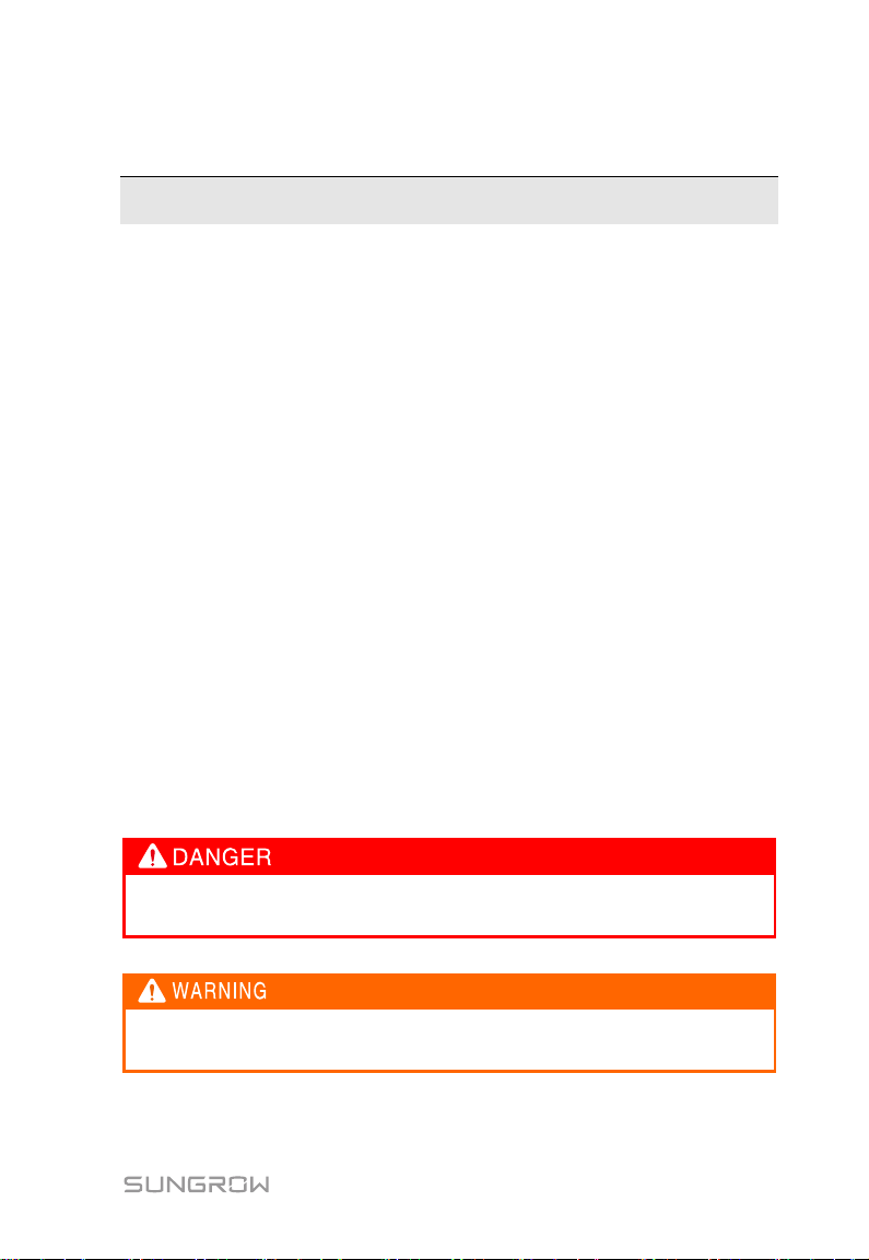
"DANGER" indicates a hazard with a high level of risk which, if not
avoided, will result in death or serious injury.
"WARNING" indicates a hazard with a medium level of risk which, if not
avoided, could result in death or serious injury.
1 About this Manual
1.1 Target Group
This manual is intended for qualified persons responsible for the installation,
operation, and maintenance of the local controller and users performing routine
operations.
1.2 How to Use this Manual
Read this manual carefully before using the device. Keep the documentation in
a convenient place for future reference.
All rights reserved including the pictures, markings, and symbols used. Any
reproduction or disclosure, even partially, of the content of this manual is strictly
prohibited without prior written authorization of our company. The content of the
manual is constantly updated or revised, and the description in this manual may
slightly deviate from the actual product or even have errors.
1.3 Symbol Explanations
To ensure personal and property safety in using the device or to use the device
efficiently, this manual provides relevant instructions that are highlighted by
corresponding symbols. Read the following symbols carefully for better using
this manual.
1
Page 8
1. About this Manual User Manual
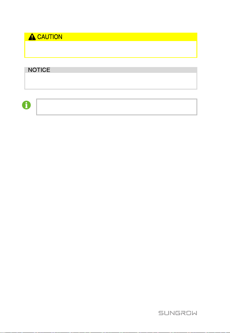
"CAUTION" indicates a hazard with a low level of risk which, if not
avoided, could result in minor or moderate injury.
"NOTICE" indicates a situation which, if not avoided, could result in
equipment malfunction or property damage.
"NOTE" indicates additional information, emphasized contents, or tips
to help you solve problems or save time.
2
Page 9
Only electrically qualified persons can operate and wire the device.
After receiving the device, check whether the local controller is
damaged due to transport. Should there be any problem, please
contact us or the forwarding company.
Before performing any operations on the local controller, the operators
must be familiar with all safety instructions and related regulations on
installation, operation, and maintenance.
Correct moving, transport, installation, operation and maintenance are
critical to safe and appropriate use of the local controller.
2 Safety Instructions
This chapter mainly introduces some important safety instructions about
operating the local controller.
The local controller is designed and tested according to the international safety
regulations. For this electrical and electronic device, safety instructions related
to it must be complied with during installation, operation, and maintenance.
Incorrect operation or misoperation may cause:
personal injury
property damage
To prevent the personal injury and property damage and to ensure long-term
operation of the local controller, read these symbols carefully.
Before Installation
3
Page 10
2. Safety Instructions User Manual
The local controller can only be used as described in this manual.
Unauthorized alternation or using spare parts not sold or
recommended by our company can cause fires, electric shock, or other
damage.
Before the installation, disconnect all electrical connections and input
switches upstream to ensure that the local controller is voltage-free.
Before the electrical connection, disconnect input switches upstream,
and ensure that the local controller is voltage-free.
Only persons from the service department of our company or other
qualified personnel can service the local controller.
The user is prohibited to perform maintenance, replacement, and other
operations. Otherwise, serious personal injury or tremendous property
loss may be caused.
Do not replace the internal components of the local controller without
authorization. Our company shall hold no liability for the damage
caused.
During Installation
Maintenance and replacement
4
Page 11
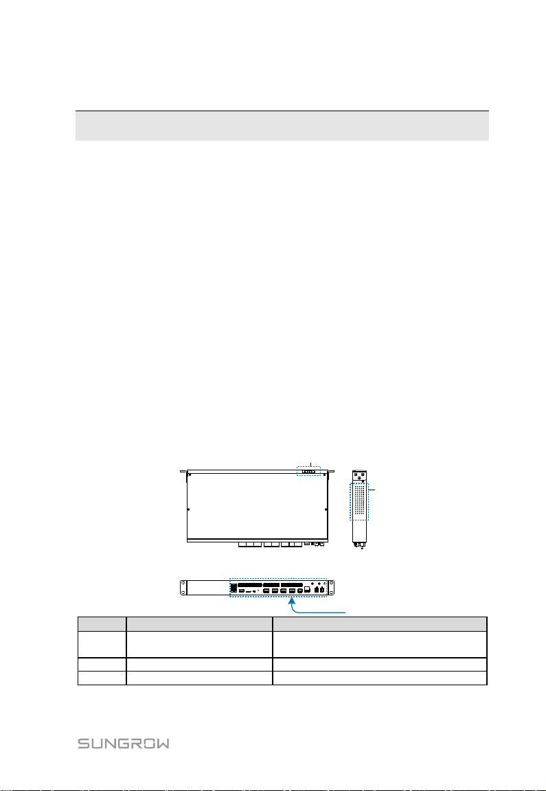
Front view Side view
Bottom view
A
B
C
Item
Name
Description
A
Indicator
Display running status of the local
controller
B
Heat dissipation hole
- C Cable connection terminal
-
3 Product Description
3.1 Function Introduction
The local controller researched & developed by our company can be applied to
the micro-grid system.
Local controller can collect running information of the PCS, BCP, and other
devices in the system, and uploads the information to the energy management
system via the background, so as to facilitate the management of energy
storage system.
Main functions
Data collection
Data forwarding
Device management
Micro-grid operation management
Receiving and executing local controller scheduling instructions
3.2 Appearance
5
Page 12
3. Product Description User Manual
Indicator
Name
Description
PWR
Power indicator
PWR indicator is on: power supply is
normal
PWR indicator is off: power supply is
abnormal
RUN
Running indicator
RUN indicator flashes: running is normal
RUN indicator is off: running is abnormal
BLE
Bluetooth indicator
Reserved function
FAULT
Fault indicator
FAULT indicator is on: the system fault
occurs
FAULT indicator is off: the connected
inverter is fault-free
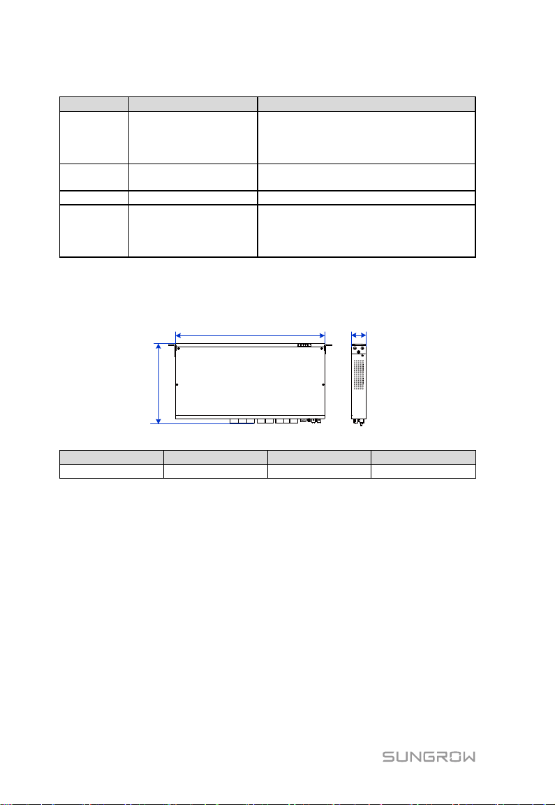
Width (W)
Height (H)
Depth (D)
Width (W)
Height (H)
Depth (D)
Weight
440
241
44
3kg
Tab. 3-1 Indicator
3.3 Dimension and Weight
Note: The unit is mm
6
Page 13
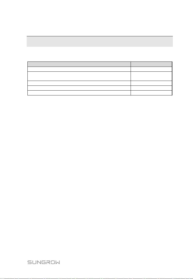
Procedure
Reference section
Unpacking and inspection
5.1
Select an optimum installation site and perform
mechanical installation
5.3
Electrical connection
6
Checking before commissioning
7.1
Running steps
7.2
4 Installation Procedure
Tab. 4-1 Description of the installation procedure
7
Page 14
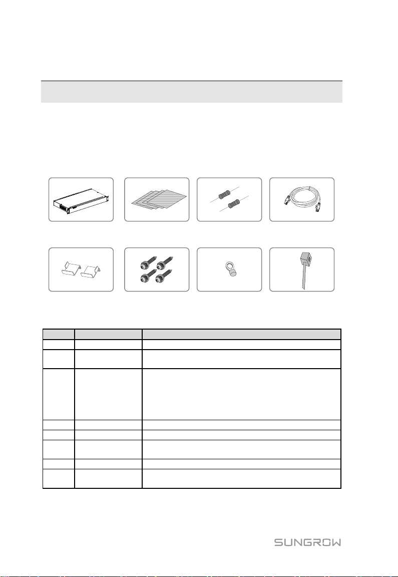
A
B
D
G
C
E
F
H
No
Name
Description
A
local controller
-
B
Enclosed
documentation
User manual, delivery inspection records, packing
list, warranty card, and quality certificate
C
Communication
terminal
resistor
12x120Ω
Note: When the RS485 bus is connected to more
than 15 devices, it is recommended to connect 120-Ω
terminal resistors in parallel to cables A and B on the
two ends of the bus
D
Network Cable
Length: 1x2m
E
Hanger
2
F
Fastener
combination
Cross recessed pan head tapping screws
G
OT terminal
RNBL5-4
H
Nylon cable
tie
Fastening cables
5 Mechanical Installation
5.1 Unpacking and Inspection
Check for completeness of the scope of delivery according to the packing list in
the carton.
Fig. 5-1 Scope of delivery
8
Page 15

User Manual 4. Mechanical Installation
440
241
5.2 Requirements for Installation Location
This section is intended to instruct the user to select an optimum installation
location.
The local controller with protection degree IP20 can only be installed
indoors.
The ambient temperature range is -30℃ to +60℃.
The humidity cannot exceed 95%. Otherwise, internal components can be
damaged.
Take proper damp-proof and anti-corrosion measures.
5.3 Installation
The local controller can be installed at any indoor locations provided that the
requirements above are met.
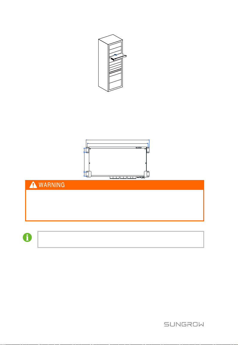
5.3.1 Rack Mounting
In the rack mounting manner, the standard 1U rack is used, and installation
steps are as follows:
Step 1 The distance between the two hangers of the local controller is shown in
the following figure.
Step 2 Select an appropriately sized rack according to the distance, and insert
the local controller into the rack.
9
Page 16
4. Mechanical Installation User Manual
150.3 31.2
465
482
31.2
Consider the weight of the local controller during the whole installation
process!
Tilting or falling of the device caused by inappropriate operations
could result in personal injury!
It is recommended to install the local controller at a location 1.5m
above the ground and reserve at least 0.5m for future maintenance.
Step 3 Fix the local controller according to the sequence of bolt, hanger, rack,
and nut.
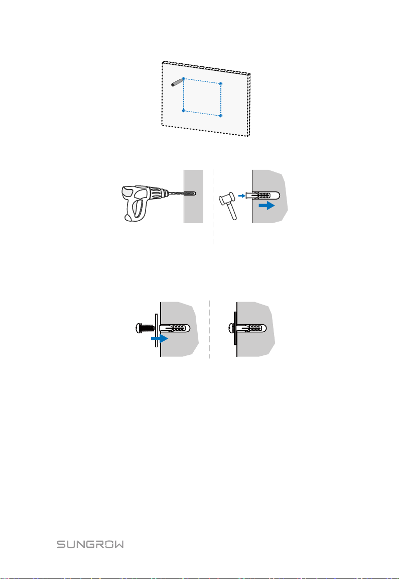
5.3.2 Wall Mounting
Fix the local controller through the hangers at the four corners. Installation
distances between the hangers are shown in the following figure.
Step 1 Prepare installation tolls including the impact drill, expansion solenoids,
washers, tapping screws, and torque screwdriver.
Step 2 Select an installation surface and mark drilling positions on the target
area considering distances between the local controller and ambient
objects.
10
Page 17
User Manual 4. Mechanical Installation
Step 3 Install the expansion solenoids, washers, and tapping screws onto the
marked positions on the surface.
Step 4 Hang the local controller onto the tapping screws via the screw holes on
the hangers.
Step 5 Fasten the tapping screws by using the torque screwdriver with fastening
torque: 0.3N·m.
Check to ensure that the local controller is firmly in place.
11
Page 18
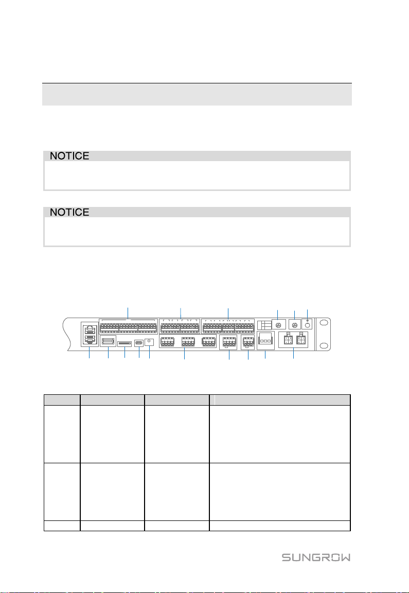
Incorrect cable connections could damage the local controller or even
injure operators.
All cables must be undamaged, well insulated, appropriately sized, and
securely connected.
ABC D E
G H
I LJF K
M N O
P
ETH2
ETH1
USB SD Debug RST
0V 1 2 3 4 5 6 7 8 9 10 11 1213 14 1516 0V
DIN
1 2 3
DO1
1 3
DO2
1 3
DO3
1 3
DO4
2 2 2
A1B1A2 B2 A3B3A4 B4 A5 B5A6 B6
+ - GND
PT1
+ - GND
PT2
+ -
AI1
+ -
AI2
+ -
AI3
+ -
AI4
H L
CAN
+ -
24V
AC(L) AC(N)
GPS/BDS RF
L1 L2
DO12
3
NO
NC
COM
Item
Remark
Name
Description
A
ETH1/ETH2
Ethernet port
ETH2 can be connected to local
controller via the switch, router, and
other devices; and ETH1 is used for
lower-layer devices (can be
connected to BCP, PCS, and the
like)
B
DIN
Digital input
Node input port
DIN1: Not assigned
DIN2: Emergency stop node
DIN3-DIN5: Not assigned
DIN6-DIN13: Optional
DIN14-DIN16: Not assigned
C
USB-HOST
USB interface
Software upgrade interface
6 Electrical Connection
6.1 General Safety Regulations
6.2 Terminal Introduction
Tab. 6-1 Terminal description
12
Page 19
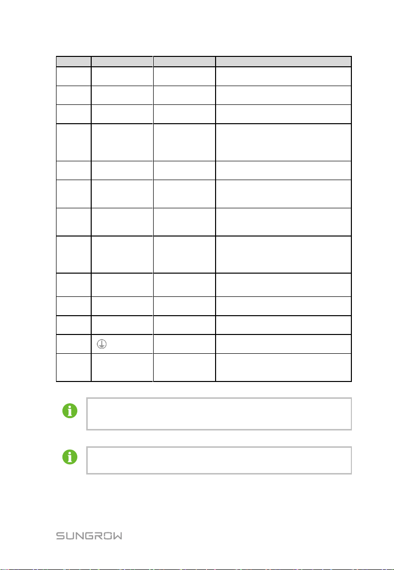
User Manual 5. Electrical Connection
Item
Remark
Name
Description
D
SD
SD card
interface
Function is reserved
E
Debug
Debugging
serial port
Used for debugging local controller
F
RST
Reset port
Used for hardware reset of local
controller
G
DO1~DO4
Digital output
Relay output ports, where the relay
specification is 250Vac/1A or
30V/1A
DO-DO4: Not assigned
H
PT1, PT2,
AI1~AI4
Analog input
Function is reserved
I
A1B1~A6B6
RS485
communicatio
n port
Supports 6 inputs of RS485, and
can be connected to slave devices
or background
J
CAN
CAN
communicatio
n port
Function is reserved
K
24V
DC24V power
supply port
Current ≤2.0A, and the
switch-mode power supply used for
this port should be insulated
intensely
L
AC
(100~240V)
AC power
supply port
Connected to 100~240Vac
(50/60Hz), and the current ≤0.5A
M
GPS/BDS
GPS antenna
port
Function is reserved
N
RF
Wireless
antenna port
Function is reserved
O
Grounding
hole
Connecting protection ground cable
P
PLC(L1/L2)
PLC
Communicatio
n port
Function is reserved
Digital input/output ports (DIN and DO1~DO4) are configured to
collect node data and control node communication.
The farthest communication distance of COM1 to COM6 (A1B1 –
A6B6) is no more than 1000m.
13
Page 20
5. Electrical Connection User Manual
High voltage on the AC power supply port! Do not operate under
voltage. Make sure the input side is completely voltage-free and the
grounding cable is reliably grounded before cable connection.
SD card does not support hot plugging.
The RS485 communication cable must be shielded twisted pair cable
and single-point grounded.
0.2mm² ≤ the maximum cross-sectional area of the shielded twisted
pair ≤ 1.2mm², and the recommended stripped length of the cable is
8mm.
Keep at least 0.5m away from the strong electricity. Avoid parallel cable
layout. Use the steel tube in area with strong interference.
It is recommended to add an SPD if an outdoor device is connected to
the local controller. Otherwise, the local controller may be damaged by
lightning.
The local controller supports a maximum of 6 RS485 buses. COM1
to COM 5 support connections to optional devices as well as PCS,
battery BMS (BMS of Samsung battery only). COM6 is used to
connect touch screen and other devices.
When more than 15 devices are connected to the RS485 bus, it is
recommended to connect 12Ω resistors in parallel to A and B of the
devices on two ends of the bus.
6.3 Communication Device Connection
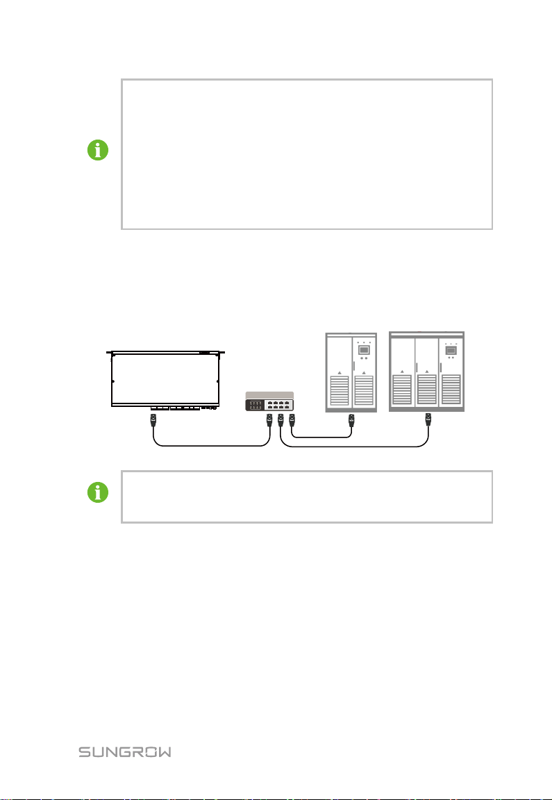
Devices that can be connected to the local controller include PCS, BCP, and the
like.
6.3.1 COM Port Connection
Devices are connected to serial ports of the local controller in the daisy chain
manner by using the RS485 bus.
14
Page 21
User Manual 5. Electrical Connection
It is recommended that devices of different models need to be
connected to the local controller separately. For example, connect
the PCS and the battery BMS to different RS485 communication
ports of the local controller.
Addresses of all devices connected to each input of the bus RS485
must be within set address range of the local controller and be
different from each other. Otherwise, communication failure occurs.
The baud rate of all devices connected to each bus RS485 must be
consistent with that of the local controller.
IP addresses of all devices must be on the same network segment
as the local controller address, and be different from each other.
Otherwise, communication failure occurs.
6.3.2 Internet Port Connection
The internet port of the local controller can be connected to the PCS. Connect
both the local controller and to-be-connected devices to the switch through
ETH1 and corresponding network ports, where Modbus-TCP communication
protocol is supported.
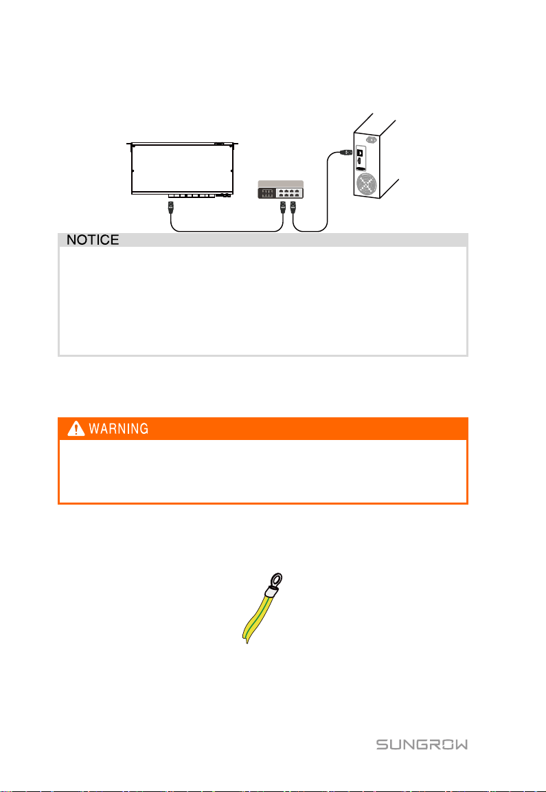
6.4 Connection to System EMS
The local controller can be connected to the system EMS via the Ethernet port,
and the communication protocol is standard Modbus-TCP.
The connection method is as follows:
In the following, an example of the connection to the background monitoring
system through the Ethernet switch is used for description.
Step 1 Insert one end of the network cable (within the scope of delivery) to the
electricity port of the Ethernet switch and the other end to the port ETH2
of the local controller.
15
Page 22
5. Electrical Connection User Manual
IP addresses of ETH1 and ETH2 cannot be on the same network
segment. Otherwise, communication error occurs.
Default IP address of ETH1 is IP192.168.0.100
Default IP address of ETH2 is IP192.168.1.100
ETH2 is used by default to set the WEB of the local controller, and the
IP address cannot activate the DHCP function.
The grounding cable must be well grounded. Otherwise:
Lethal electrical shock occurs to the operator in a fault case!
The device can be damaged by lightning!
Step 2 Set ETH2 IP address of the local controller to be on the same network
segment as that of the background monitoring system.
6.5 Protection Earthing Connection
Step 1 Prepare the grounding cable (recommended: outdoor copper-core cable
with cross-sectional area of 4mm2 to 6mm2 or 12AWG to 10AWG) and
OT terminal.
Step 2 Crimp the grounding terminal shown in the following figure.
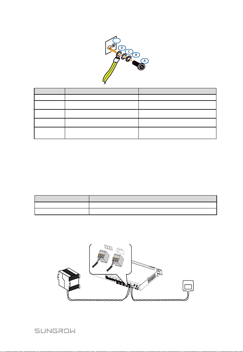
Step 3 Tighten the M4 screw to the grounding hole according to the sequence
shown in the figure below by using the wrench with fastening torque: 5±
1N·m.
16
Page 23
User Manual 5. Electrical Connection
E
Item
Definition
Note
A
Screw
M4
B
Spring washer
——
C
Flat washer
——
D
OT terminal
——
E
Grounding hole of the local
controller
——
Cable
Recommended cross-sectional area
AC cable
Cross-sectional area: 1mm
2
to 1.5mm
2
DC cable
Cross-sectional area: 0.75mm
2
to1mm
2
DC(UPS)
AC
6.6 Power Supply Connection
The local controller supports DC24V DC input or AC100 to 240V (50/60HZ) AC
input. This section will take the AC power supply for example.
Step 1 Prepare power cables and phoenix terminal. Specifications of the AC &
DC cables are shown in the following table:
Step 2 Remove the phoenix terminal at the power supply port of the local
controller, and crimp the power supply terminal.
Step 3 Insert the power supply terminal to the corresponding DC/AC power
supply port.
17
Page 24

5. Electrical Connection User Manual
The local controller can connect to the DC and AC power at the
same time. The DC power can be connected to the UPS and used
as the standby power supply.
18
Page 25
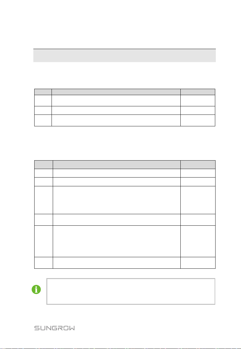
No.
Inspection item
Result
1
Whether all cables are undamaged, well insulated, and
appropriately sized.
□
2
Whether all cable are securely in place.
□
3
Whether the power supply cable and the grounding cable
are correctly connected.
□
No.
Commissioning steps
Result
1
Inspection before commissioning
□
2
The local controller is powered on
□
3
Connect the debugging PC to the ETH2 (default IP
address of the port is 192.168.1.100) of the local
controller by using the cable.
Log into the local controller operation interface via the IE
browser or the Google browser.
□
4
Ensure that the device is firmly connected to the local
controller.
□
5
Perform system networking configuration and
communication parameter configuration on the WEB
page, where the type of actual connected device,
operation strategy, and the like are consistent with actual
system requirements.
□
6
The system starts commissioning. Observe whether the
device communication parameter is normal.
□
Notice: Device addresses should be different for the same
communication port.
Save operations. Otherwise, the settings are invalid.
7 Commissioning
7.1 Checking before Commissioning
7.2 Running Steps
Tab. 7-1 Commissioning steps
19
Page 26
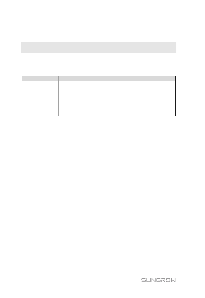
Item
Requirement
System
requirement
WIN7, WIN8, and WIN10
Browser version
IE10 to IE11 and CHROME43 to CHROME45
Minimum
resolution
1366*768
CPU
The clock speed is above 2.5G Hz
Memory
More than 4GB
8 WEB Interface
8.1 Requirements for Operation Environment
8.2 Preparations for Login
Set IP address of the PC to be on the same network segment as that of the
local controller.
Connect the PC to the port ETH2 of the local controller.
The default IP address of the port ETH2 is 192.168.1.100. IP address of the
PC can be set to 192.168.1.125 when the subnet mask can be set to
255.255.255.0.
8.3 Login Steps
Step 1 Connect the local controller to the PC by using the Ethernet cable.
Step 2 Enter the IP address, for example, 192.168.1.100, of the local controller
in the PC address bar to enter the login interface shown in the picture
below.
Step 3 Enter the username and password, and click login.
20
Page 27
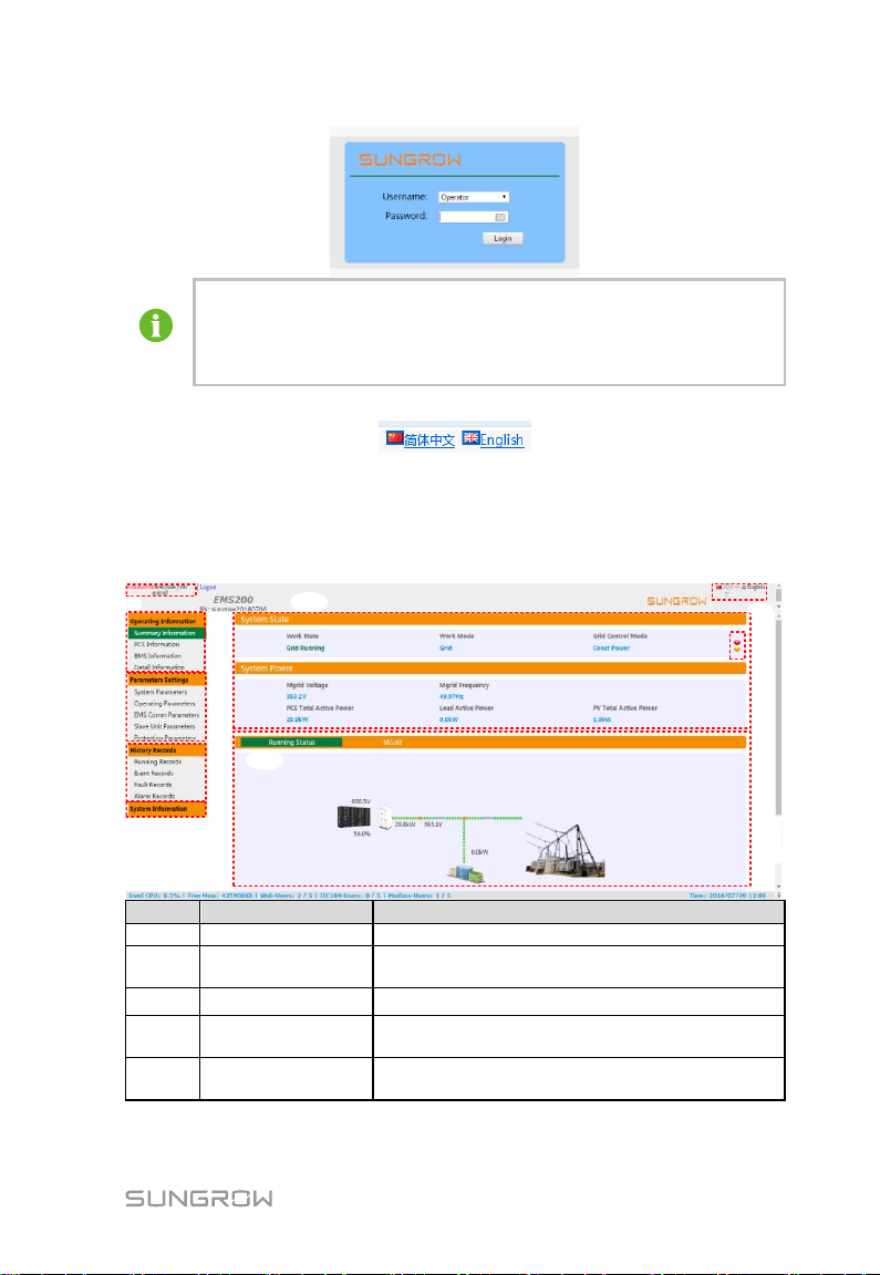
User Manual 8. WEB Interface
In the system, there are three types of users: "operator", "administrator",
and "maintainer".
Default password of the "operator" is 1111, and passwords of the other
two types of users can be obtained from the SungrowSumsung Energy
Storage Power Supply Co., Ltd.
A
C
D
E
B
F
G
H
I
Item
Name
Description
A
Username
Display the current login user
B
Operating
information
Display detailed information of the system access
device
C
Parameter settings
Set system running-related parameters
D
History Records
Display history running records, history alarms,
history faults, and history events of the system
E
System
information
Display the software version and used for
changing user password
Step 4 Select the desired language on the upper righter corner of the interface.
8.4 WEB Main Interface
The WEB interface is shown in the following picture.
21
Page 28

8 WEB Interface User Manual
Item
Name
Description
F
Display of
summary
operating
information
Current operating mode and summary operating
information of the system
G
System schematic
diagram
Schematic diagram of system running
H
Language option
Used for switching between Chinese and English
interfaces
I
Fault and alarm
Detailed fault and alarm information of the system
WEB Main
Interface
Operating
Information
Parameters
Settings
History
Records
System
Information
Summary
Information
Running
Records
Event Records
Fault Records
Alarm Records
PCS
Information
BMS
Information
System
Parameters
Operating
Parameters
EMS Comm
Parameters
Slave Unit
Parameters
Protection
Parameters
Detailed
Informatioin
When the local controller is connected to different systems and
devices, the operating information interface is different.
When the connected device is set to the "enable" and "disable" states,
device types and device names displayed on the operating information
8.5 WEB Menu
The WEB Menu includes four main function modules: "Operating Information",
"Parameter Settings", "History Records", and "System information".
Specific classifications of the administrator menu is shown in the following
figure.
8.6 Operating Information
22
Page 29
User Manual 8. WEB Interface
interface are also different. Please refer to the actual interface.
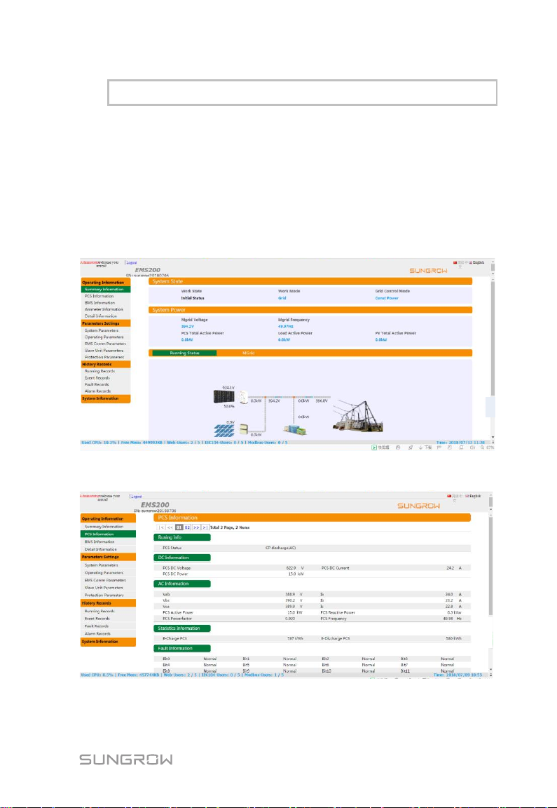
The "Operating Information" indicates detailed information of the system and
the connected device, and includes:
"Summary Information", "PCS Information", "BMS Information", and "Detail
Information".
8.6.1 Summary Information
The summary information interface differs due to different system configuration
interface parameters. Please refer to the actual interface, and details are not
described herein.
8.6.2 PCS Information
The PCS Information includes:
detailed information of each PCS connected to the system.
23
Page 30
8 WEB Interface User Manual
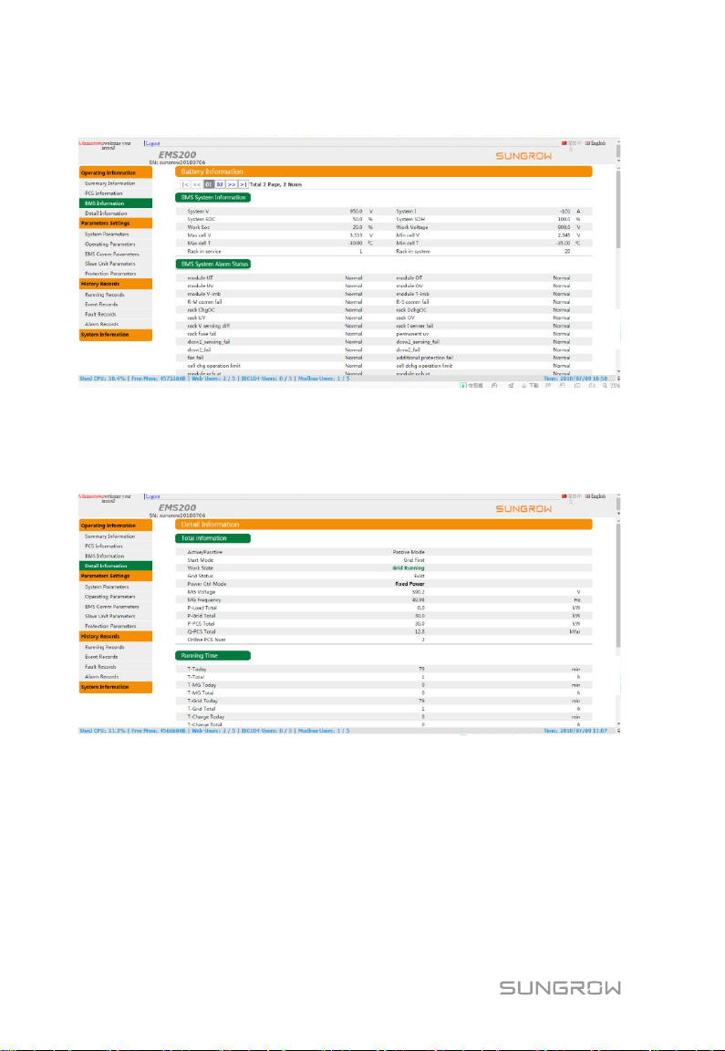
8.6.3 BMS Information
The BMS Information includes:
detailed information of each battery connected to the system.
8.6.4 Detail Information
The Detail Information includes
operating information of the whole system, for example, total active power of
the PCS.
8.7 Parameter Settings
The "Parameters Settings" are used to set parameters relevant to system
running and include "System Parameters", "Operating Parameters", "local
controller Comm Parameters", "Slave Unit Parameters", and "Protection
24
Page 31
User Manual 8. WEB Interface
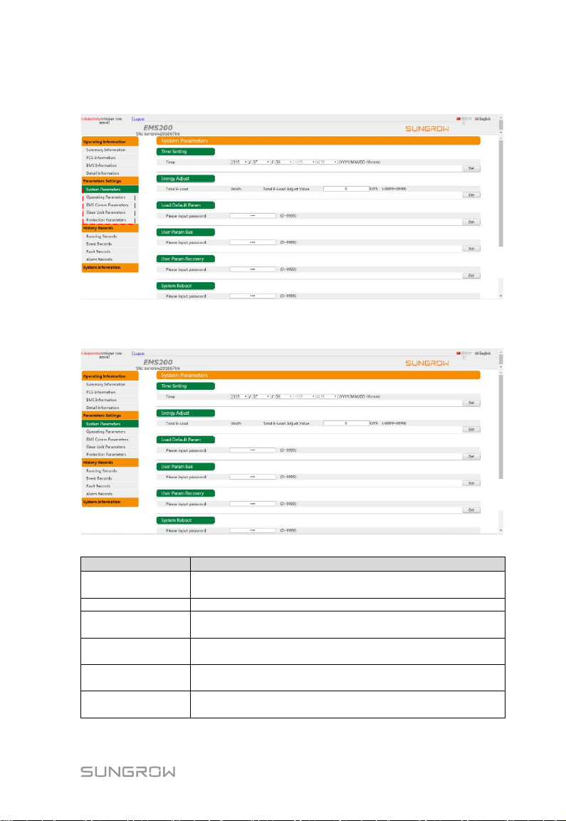
Parameter
Description
Time setting
Set the system time with the format
minute/hour/day/month/year
Energy adjust
Set the energy adjustment value
Load default
param
Enter the set password 1111 to restore factory defaults
User param bak
Enter the set password 1111 to backup current system
configuration information
User param
recovery
Enter the set password 1111 to recover parameters set by
the user
system reboot
Enter the set password 1111 to reboot the system
Notice: Do not reboot the system in running state
Parameters".
8.7.1 System Parameters
The System Parameters include the following settings:
25
Page 32
8 WEB Interface User Manual
Parameter
Description
NTP parameters
After checking "enable NTP time synchronization",
synchronize the time to the NTP server (such as PC and
Internet server)
Set server address and port number
Parameter
Description
Mode setting
Set to "Running Mode", "Power Control Mode", "Grid
Power", or "Off-Grid power"
Q-ac regulation
That includes "Close", "Power Factor", and “Q-ac Power”
BMS control
Setting closing or opening of the BMS switch
Start type
Set the active or passive mode
Start & stop
control
Set to start or stop
Parameter
Description
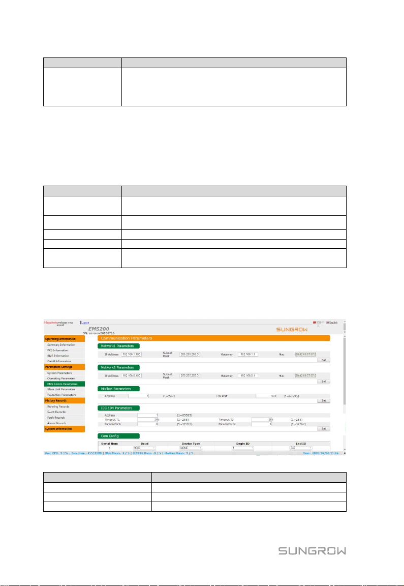
Network 1 parameters
Default IP address: 192.168.1.100
Network 2 parameters
Default IP address: 192.168.0.100
parameters
Set the Modbus parameter and TCP port number
8.7.2 Operating Parameters
Different parameters are set for the system configuration interfaces, and the
running parameter interfaces are different accordingly. Please refer to the
actual interfaces, and details are not described herein.
The Operating Parameters include the following settings.
Note: The table above includes all parameters that can be set, but actual
configurable parameters and interfaces may vary as per system configuration.
8.7.3 Communication Parameters
The communication parameters include the following settings:
26
Page 33
User Manual 8. WEB Interface
Parameter
Description
IEC-104 parameters
Timeout T1: acknowledgement timeout of the
control packet.
Timeout T2: Response timeout of the monitoring
packet, where T2<T1.
Parameters k and w: K is the largest number, and
W is latest acknowledgement number. The sender
stops sending after sending K packets, and the
receiver performs acknowledgement after receiving
w packets.
Range: 1 to 32767
Recommended: w<k*2/3, where k is 12, and w is 8.
Communication port
configuration
According to the specific connected
communication cable, select the type of the device
connected to the corresponding port.
If the PCS communication cable is connected to
the serial port 1, the PCS is selected as the
device type for the serial port 1. The start ID is
set to 1, and the end ID is set to 247.
If a device connects to 2 serial ports, start IDs
and end IDs of the two serial ports should be
different from each other.
Maximum device number
Used for setting numbers of devices of different
types in the system according to the actual
situation. The set number should be equal to the
number of actually connected devices.
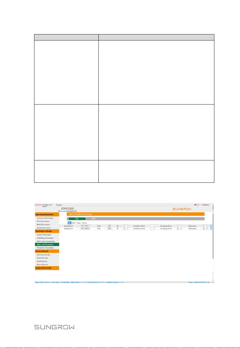
8.7.4 Slave Unit Parameters
The Slave Unit Parameters are used to set communication address of the
connected device. For example, for the PCS communication method, select an
internet port mode, and set IP address, port number, and Modbus ID for each
device.
27
Page 34
8 WEB Interface User Manual
Parameter
Description
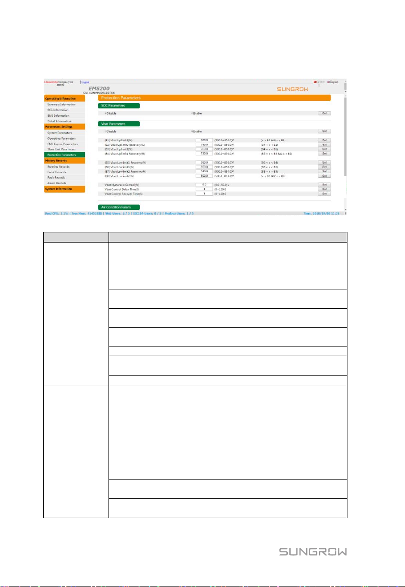
SOC
Parameters
Disabled
If it is enabled, the local controller controls charge and
discharge power of the system according to battery SOC
information read from the BMS, so as to keep the battery SOC
operating within the set section.
SOC upper limit 1 (2) level: battery charge SOC 1 (2) level
upper limit
SOC lower limit 1 (2) level: battery discharge SOC 1 (2) level
upper limit
SOC lower limit 1 (2) recovery: battery lower limit 1 (2) level
alarm recovery value
SOC hysteresis control
SOC control delay time (s): delay of triggering battery SOC
alarm
SOC control recover time (s): SOC alarm recovery delay
Vbat
Parameters
Disabled
If it is enabled, the local controller controls charge and
discharge power of the system according to battery SOC
information read from the PCS, so as to keep the battery
voltage within the set section.
In case of grid connection, the battery SOC or the voltage
charge and discharge sections is at the lower limit 1 to the
upper limit 1.
In the off-grid case, the battery SOC or the voltage section is
above the lower limit level 2.
Vbat upper limit 1 (2) level: battery charge voltage 1 (2) level
upper limit
Vbat lower limit 1 (2) level: battery discharge voltage 1 (2) level
upper limit
8.7.5 Protection Parameters
The local controller protection parameters include the following settings:
28
Page 35
User Manual 8. WEB Interface
Parameter
Description
Vbat lower limit 1 (2) recovery: battery lower limit 1 (2) level
alarm recovery value
Vbat hysteresis control
Vbat control delay time(s): delay of triggering battery voltage
alarm
Vbat control recovery time (s): Vbat alarm recovery delay
Air Condition
Param
Set alarm temperature thresholds
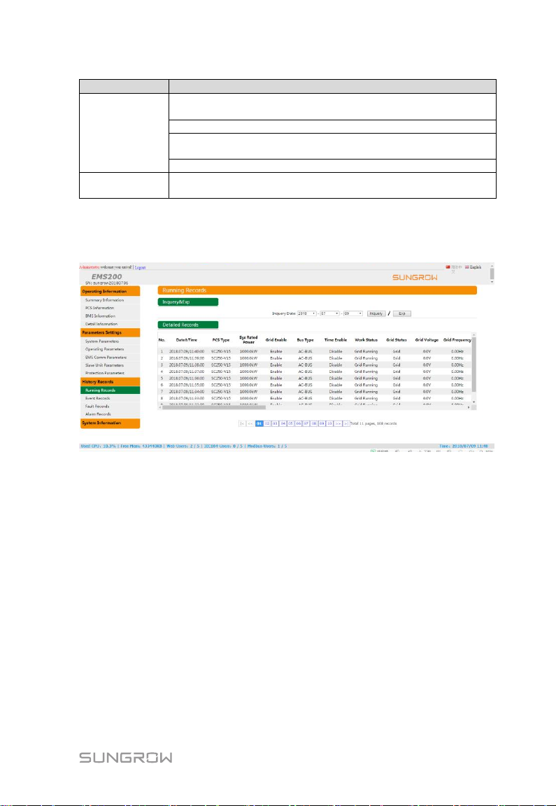
8.8 History Records
The History Records include "Running Records", "Event Records", "Fault
Records", and "Alarm Records". A maximum of 10,000 history records can be
stored, and the records can be exported in the CSV format.
29
Page 36
8 WEB Interface User Manual
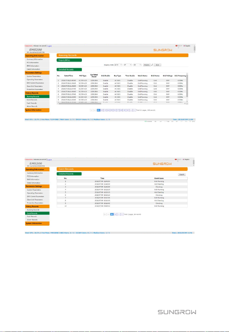
8.8.1 Running Records
The Running Records include a maximum of 10,000 history records. During
running, the system automatically records once every minute. The records
within specified time can be queried, and the CSV export format is supported.
8.8.2 Event Records
The Event Records include a maximum of 10,000 history records. When status
changes occur, the system automatically records. Records within specified time
can be queried, and the CSV export format is supported.
30
Page 37
User Manual 8. WEB Interface
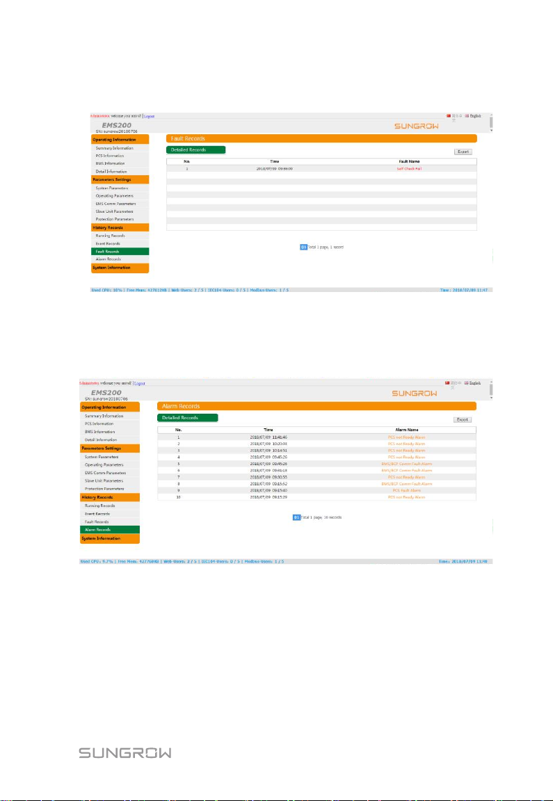
8.8.3 Fault Records
The Fault Records include a maximum of 10,000 history records. When faults
occur, the system automatically records. The records within specified time can
be queried, and the CSV export format is supported.
8.8.4 Alarm Records
The Alarm Records include a maximum of 10,000 history records. When alarms
occur, the system automatically records. The records within specified time can
be queried, and the CSV export format is supported.
31
Page 38
8 WEB Interface User Manual
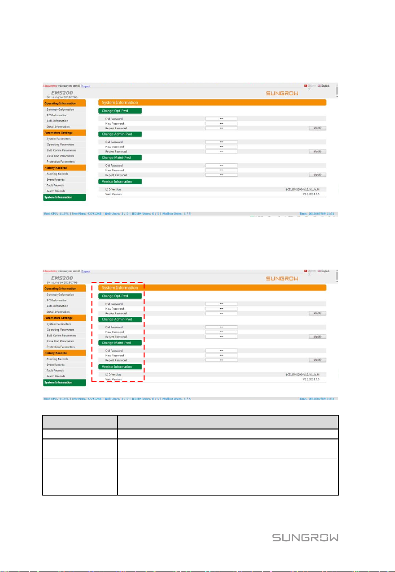
User type
Permission
Operator
Can view running information, but cannot set parameters.
Maintainer
Can view running information and set parameters, but
cannot change passwords of subordinate users.
Administrator
Can view running information, set parameters, and change
passwords of subordinate users.
Note: Ask Sungrow for the administrator account and
password.
8.9 System Information
The System Information includes: changing passwords of all types of users and
displaying software version.
User Password Changing
32
Page 39
Only approved qualified persons can service the local controller.
Do not leave any screws, washers, or other metallic parts inside the
local controller. Otherwise, the device can be damaged.
After the local controller stops, wait at least 5 minutes before operating
it.
9 Routine Maintenance
Affected by ambient temperature, humidity, dust, vibration, and the like, the
internal components of the local controller will be aging and be worn out.
Consequently, potential faults occur in the local controller. Therefore, it is
necessary to maintain the local controller regularly to ensure normal and
long-term operation.
All operations that can keep the local controller be in good working conditions
fall within the maintenance scope.
9.1 Safety Precautions
9.1.1 General Safety Rules
9.1.2 Five Safety Rules
Observe the following five rules during maintenance or troubleshooting to
ensure personal safety.
Disconnect the local controller from all external connections and internal
power supplies.
Ensure that the local controller will not be powered on accidentally.
Verify that the local controller interior is completely voltage-free with a
multimeter.
Perform necessary grounding connections.
33
Page 40

9 Routine Maintenance User Manual
Item
Method
Operation
environment
Check to ensure that there is no strong EMI device
around the local controller.
Check to ensure that there is no hot source around the
local controller.
Check to ensure that there is no corrosive materials
around the local controller.
Hardware
maintenance
Check to ensure that the power supply voltage is normal.
Check to ensure that the cables are connected firmly.
Check to ensure that the cable is grounded well.
System cleaning
Clean the enclosure, circuit board, and components.
Clean the heat dissipation holes and the cover.
Terminal and
cable connection
Check if the screws of the control terminals are loose,
and refasten them with screwdriver if necessary.
Check if the connection copper bar or screws are
discolored.
Check the wiring layout and the device terminal
connections.
Software
maintenance
Log into the WEB to check the device communication
status.
Log into the WEB to check parameter settings of the
local controller.
Log into the WEB to check the software version of the
local controller.
Cover the possible live components with insulation cloth during operation.
9.2 Routine Maintenance
The following maintenance work is recommended.
34
Page 41
The ground cable must be grounded well, otherwise,
Fatal electric shock may occur to the operators!
Alarm
Possible causes
Measures
PCS
Fault/Alarm/EMGStop
1. A fault or an alarm
occurs.
1. Troubleshoot the PCS
according to the PCS
manual.
2. An emergency stop
occurs on the PCS.
2. Check whether the PCS
is in emergency stop state.
PCS Comm Fault
Alarm
Communication between
the PCS and the local
controller failed.
1. Check whether the
communication connection
between the PCS and the
local controller is firmly in
place.
10 Troubleshooting
10.1 Overview
The common faults and troubleshooting are shown in the table below. If
problems cannot be resolved according to this manual, please contact us. We
need the following information in order to provide you with better assistance.
The SN, the manufacture date, and the software version of the local
controller
The manufacturers, the models, and the configuration information of the
devices connected to the local controller
Brief fault description
Pictures of the fault site
10.2 Alarm Diagnosis
10.2.1 Alarm Information on Power Conversion System (PCS)
35
Page 42

10 Troubleshooting User Manual
Alarm
Possible causes
Measures
2. Check whether the IP
address and Modbus
address of the PCS are
correctly set.
PCS AC- side
Disconnect
AC circuit breaker of the
PCS is open.
Close the AC circuit
breaker.
PCS Direct Grid V-Diff
too Large Alarm
In the case that multiple
PCSs are directly
connected in parallel on
the AC side, battery
voltages on the DC side
differ from each other,
and the difference
exceeds the set value.
1. Check whether the
parameter is set to an
appropriate value.
2. Check whether "Balance
Control Enable" is enabled.
3. Check whether voltage
equalization is invalid.
PCS not Ready Alarm
1. The PCS is faulty.
1. Check whether PCS has
a fault.
2. An emergency stop
occurs on the PCS.
2. Check whether the PCS
is in the emergency stop
state.
3. PCS container node
collects node fault.
3. Check whether the dry
contact in the PCS
container is faulty.
4. The BCP is faulty.
4. Check whether faults
occur in the BCP.
5.The number of racks in
normal operation is less
than the lower limit.
5. Check whether The
number of racks in normal
operation is less than the
lower limit.
Note: When the alarm
occurs, the corresponding
devices (including the PCS,
PCS container, battery,
and battery container)
cannot operate.
Note: * applicable only to SC1000 whose AC side is directly connected in
parallel.
36
Page 43

User Manual 10 Troubleshooting
Alarm
Possible
causes
Measures
Note
One or More
Low Battery
Level1
Battery
voltage/SOC is
lower than the
"Vbat Lowlimit1".
1. Reduce
discharging power.
In the on-grid
mode, the local
controller will limit
the discharging
power of the PCS
until it drops to 0,
but the charging
power is not
affected.
In the off-grid
mode, the
user-side EMS
needs to control
external load
power.
2. Check whether
the protection
parameter is set to
an appropriate
One or More
High Battery
Level1
Battery
voltage/SOC is
higher than the
"Vbat Uplimit1".
1. Reduce
charging power
In the on-grid
mode, the local
controller will limit
the charging power
of the PCS until it
drops to 0, but the
discharging power
is not affected.
In the off-grid
mode, the
user-side EMS
needs to limit the
external power to
be fed into the
system.
2. Check whether
the protection
parameter is set to
an appropriate
value.
One or More
Low Battery
Level2
Battery
voltage/SOC is
lower than the
"Vbat Lowlimit2".
1. Stop
discharging.
In the on-grid
mode, the local
controller will
control the PCS to
enter the standby
state (or control the
PCS to perform
10.2.2 Alarm Information on Battery
37
Page 44

10 Troubleshooting User Manual
Alarm
Possible
causes
Measures
Note
2. Check whether
the protection
parameter is set to
an appropriate
value.
zero-power
operation if there is
no standby state),
but the charging
power is not
affected.
In the off-grid
mode, the local
controller will
control the system
to shut down.
One or More
High Battery
Level2
Battery
voltage/SOC is
higher than the
"Vbat Uplimit2".
1. Stop charging
In the on-grid
mode, the local
controller will
control the PCS to
enter the standby
state (or control the
PCS to perform
zero-power
operation if there is
no standby state),
but the charging
power is not
affected.
In the off-grid
mode, the
user-side EMS
needs to stop the
external power
being fed into the
system.
2. Check whether
the protection
parameter is set to
an appropriate
value.
Battery Group
DC V-Diff too
Large
For multiple of
BCPs, or the
system in which
battery DC sides
are directly
connected in
parallel, "Battery
Direct Connect
Voltage Value" is
greater than the
set value.
1. Check whether
the parameter is
set to an
appropriate value.
When the alarm
occurs, the local
controller does not
respond to the
instruction sent by
the customer EMS
to close the BMS
contactor.
2. Check whether
the system voltage
difference between
battery racks
whose DC sides
are connected in
parallel is relatively
large.
38
Page 45

User Manual 10 Troubleshooting
Alarm
Possible
causes
Measures
Note
Low online rack
num
For the standard
battery, the alarm
occurs when the
online Rack
number is lower
than the set
"Rack Num".
1. Check whether
the batteries are
faulty.
-
2. Check whether
the related
parameter of the
local controller is
appropriately set.
BMS Comm
Fault Alarm
Communication
between the
BMS and the
local controller
failed.
1. Check whether
the communication
cable connecting
the BMS and the
local controller is
firmly in place.
-
2. Check whether
the IP address and
Modbus address of
the BMS are
correctly set.
3. Check whether
the serial port via
which the BMS is
connected to the
local controller is
correctly
configured.
BMS Fault
Alarm
The battery
system or Rack
is faulty.
Refer to the
measures for
battery fault.
-
BMS Alarm
The battery
system or Rack
gives an alarm.
Refer to the
measures for
battery alarm.
-
Alarm
Possible causes
Measures
BCP Alarm(including
BCP fault, alarm,
emergency stop)
A fault or an alarm
occurs in the external
devices connected to the
BCP, such as air
conditioner and smoke
sensor.
Check whether the devices
connected to the BCP,
such as the air conditioner
and smoke sensor run in
the normal state.
If a fault such as smoke
sensor overtemperature
occurs or fire fighting is
10.2.3 Alarm Information on BCP
39
Page 46

10 Troubleshooting User Manual
Alarm
Possible causes
Measures
triggered, the local
controller shuts down this
battery rack and the BCP
BCP Comm Fault
Alarm
Communication between
the BCP and the local
controller failed.
1. Check whether the
communication cable
connecting the BCP and
the local controller is firmly
in place.
2. Check whether the IP
address and Modbus
address of the BCP are
correctly set.
3. Check whether the serial
port via which the BMS is
connected to the local
controller is correctly
configured.
Alarm
Possible causes
Measures
Node collector Comm
Fault Alarm
Communication between
the PCS dry contact and
the local controller failed.
1. Check whether the
communication cable
connecting the node and
the local controller is firmly
in place.
2. Check whether the IP
address and Modbus
address of the node
contactor are correctly set.
Node Collector Node
Abnormal
The PCS dry contact
collects node signals.
Check whether the device
connected to the
corresponding dry contact
is normal.
The dry contact can be
configured for alarm or fault
collection.
When it is configured for
alarm, the node reports
alarm information.
When it is configured for
fault collection, the node
can control all PCSs in the
container to shut down via
10.2.4 Other Alarms
40
Page 47

User Manual 10 Troubleshooting
Alarm
Possible causes
Measures
the local controller.
Node 1/2/3/4/5/6/7/8
Alarm
Dry contact of the local
controller collects node
signals.
Check whether the device
connected to the
corresponding dry contact
is normal.
The dry contact can be
configured for alarm or fault
collection.
When it is configured for
alarm, the node reports
alarms.
Air Condition
Temperature
Abnormal
The actual temperature
in the battery container is
higher than "Air
Condition T Uplimit
Value" or Air Condition T
Lowlimit Value ".
1. Check whether the air
conditioner in the battery
container is faulty.
2. Check whether the
parameters such as "Air
Condition T Uplimit Value"
or Air Condition T Lowlimit
Value ". are appropriately
set.
Master Alloc
Abnormal Alarm
When multiple PCSs are
directly connected in
parallel on the AC side,
there is no master or
more than one master.
Check the setting of master
and slave.
Fault
Possible causes
Measures
PCS fault
1. The grid is powered
off and the PCS is faulty.
1. Check the grid state, and
check whether the voltage
frequency is normal.
Note: * applicable only to SC1000 whose AC side is directly connected in
parallel.
10.3 Fault Diagnosis
10.3.1 Fault Information on Power Conversion System (PCS)
41
Page 48

10 Troubleshooting User Manual
Fault
Possible causes
Measures
2. PCS AC circuit
breaker is open.
2. Check whether the PCS
AC circuit breaker is
closed.
PCS comm fault
The grid is powered off
and the PCS fails to
communicate with the
local controller.
1. Check the grid state, and
check whether the voltage
frequency is normal.
2. Check whether the
communication cable
connecting the PCS and
the local controller is firmly
in place.
3. Check whether the IP
address and Modbus
address of the PCS are
correctly set.
PCS Address Conflict
Multiple PCSs have the
same Modbus address.
Check the Modbus address
setting.
PCS not Ready Fault
Refer to " PCS not Ready Alarm".
Micro start timeout
1. The PCS is in the
local mode.
1. Check whether the PCS
is in the local mode.
2. Communication
between the PCS and
the local controller is
abnormal.
2. Check whether the
communication between
the PCS and the local
controller is normal.
Micro Start Fail
1. The PCS is connected
to the grid.
1. Disconnect the PCS
from the grid.
2. The Soft-Start Voltage
is abnormal.
2. Check whether the
Soft-Start Voltage is
normal.
3. The micro-grid voltage
range is inappropriate.
3. Check whether the
micro-grid voltage range of
the local controller is
appropriately set.
Stop timeout
1. The PCS is in the
local mode.
1. Check whether the PCS
is in the local mode.
2. Communication
between the PCS and
the local controller is
abnormal.
2. Check whether the
communication between
the PCS and the local
controller is normal.
42
Page 49
User Manual 10 Troubleshooting
Fault
Possible causes
Measures
Grid Start Timeout
1. The PCS is in the
local mode.
1. Check whether the PCS
is in the local mode.
2. Communication
between the PCS and
the local controller is
abnormal.
2. Check whether the
communication between
the PCS and the local
controller is normal.
Grid Start Fail
1. The gird is abnormal.
1. Check whether the grid
frequency or voltage is
abnormal.
2. The grid voltage range
is inappropriate.
2. Check whether the grid
voltage range is
appropriately set.
Fault
Possible causes
Measures
Upper Computer
Comm Err.
Communication between
the local controller and
the user-side EMS times
out.
1. Check whether the
communication cable
between the local controller
and EMS is firmly in place.
2. Check whether the
communication between
the EMS and the local
controller is normal.
Self Check Timeout
PCS is running in the
local mode.
Check whether the PCS is
in the local mode.
Self Check Fault
1. The gird is abnormal.
1. Check the grid status.
2. PCS is faulty or shuts
down due to emergency.
2. Check whether the PCS
is faulty or has shut down
due to emergency.
3. The battery is faulty.
3. Replace the faulty
battery.
4. Container node is
faulty.
4. Check the status of the
container node.
Master Alloc
Abnormal
Refer to the "Master Alloc Abnormal Alarm".
10.3.2 Fault Information on Grid
10.3.3 Other Faults
43
Page 50

10 Troubleshooting User Manual
Fault
Possible causes
Measures
Nodes 1-8 Fault
Dry contact collection
port of the local
controller collects node
signals.
Check whether the device
connected to the
corresponding dry contact
is normal.
The dry contact can be
configured for alarm or fault
collection.
When it is configured for
fault collection, the node
can control the system to
shut down via the local
controller.
Power-on failure
1. The power supply port
of the local controller is
not connected to the
power source.
1. Check whether the
power cable connecting the
local controller is firmly in
place.
2. The power source is
faulty.
2. Replace the power
source.
3. The local controller is
faulty.
3. Contact us.
Failure to
communicate with
background
1. Communication
between the local
controller and the
background failed.
1. Check whether the
Ethernet port of the local
controller is firmly in place
to the PC or router.
2. The network
parameter is incorrectly
set.
2. Check whether the
network parameter is
correctly set.
3. The forwarding
protocol is incorrectly
configured.
3. Check whether the
forwarding protocol is
correctly configured.
44
Page 51
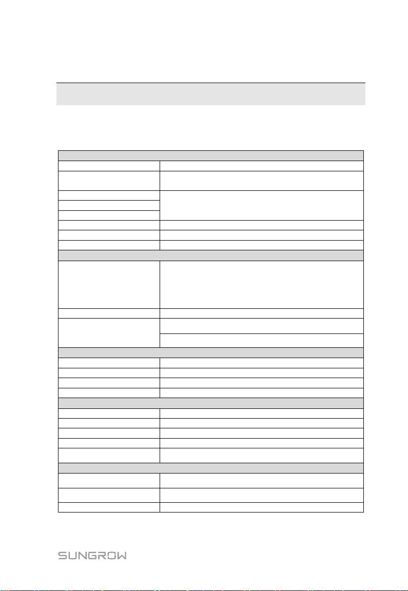
Port
Ethernet
2 inputs, 10/100M
RS485
6 inputs
Support baud rates 9600 to 38400
USB
Reserved function
CAN
SD
Digital input
16 inputs
Digital output
4 inputs
Analog input
Reserved function
Device connection
Max. device number
Maximum device numbers:
60 PCSs
60 BMSs
60 groups
60 sub-systems
Communication manner
RS485 and Ethernet
Max. communication
distance
RS485: 1000m(COM1~COM6)
Ethernet: 100m
Other parameter
Display
WEB and LED indicator
Language
Chinese , English
Power supply
AC100 to 240V(50/60HZ) or DC12 to 24V
Power consumption
Typically 5W and 10W at most
Mechanical parameter
Dimension (W*H*D)
440x241x44mm
Weight
3kg
Protection degree
IP20
Installation method
Wall mounting and rack mounting
Altitude
≤4000m
Environmental parameter
Operation temperature
-30℃ to +60℃
Storage temperature
-40℃ to +85℃
Operation humidity
0 to 95% and no condensation
11 Appendix
11.1 Technical Data
45
Page 52

11 Appendix User Manual
Abbreviation
Explanation
PCC
Point of Common Coupling
BMS
Battery Management System
CAN
Control Area Network
CC
Constant Current
CP
Constant Power
CV
Constant Voltage
DOD
Depth of Discharge
MCCV
Maximum Charge Current
MDCV
Maximum Discharge Current
RH
Relative Humidity
SOC
State of Charge
SOH
State of Health
NTP
Network Time Protocol
11.2 Abbreviation Explanation
11.3 Quality Assurance
Evidence
Within the warranty period, SungrowSamsung (Hefei) will require the customer
to present the purchase invoice and date. The trademark on the product shall
be clearly visible. Otherwise, SungrowSamsung shall hold no liability.
Conditions
If the product covered by warranty becomes defective during warranty period,
SungrowSamsung (Hefei) will provide a totally-free repair or exchange.
The unqualified product that is replaced shall be returned to
SungrowSamsung (Hefei).
Customers shall leave proper time for us to repair the failed device.
Damage and claims arising from the followings are not covered by the warranty
of SungrowSamsung (Hefei):
Transport damage
46
Page 53
User Manual 11 Appendix
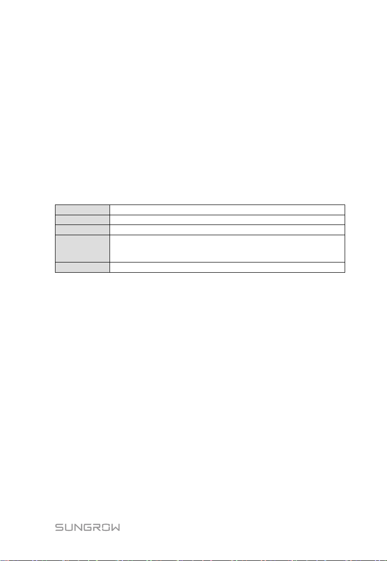
Company:
Sungrow-Samsung SDI Energy Storage Power Supply Co., Ltd.
Website:
www.sungrowsamsung.com
Email:
Address:
No. 788 Mingchuan Rd., Baiyan Science and Technology Park,
New & High Technology Industrial Development Zone, Hefei, P.
R. China.
Telephone:
+86 551 6532 6000
Incorrect installation
Incorrect alternation
Inappropriate operation
Use of this product in harsh environment beyond the specification in this
manual
Damage caused by abnormal natural environment
11.4 Contact Information
Should you have any questions or queries about this product, please contact us
through the following information. We will be more than happy to assist you!
47
 Loading...