

SungJin Techwin Co DiSS NetMaster NM-1004, DiSS NetMaster NM-2004DL, DiSS NetMaster NM-1008, DiSS NetMaster NM-2008DL, DiSS NetMaster NM-2016DL User Manual

DiSS NetMaster
NM-1000/2000 Series
NM-1004/1008
NM-2004DL/2008DL/2016DL
User Manual
※
The picture might differ according to the specifications.
©
1997-2004
Sungjin C&C
Contents of this user manual and NM-2016DL software are protected under copyrights and computer program laws.
First Edition June 1
st
, 2004.
3rd Floor, B-dong, SKTwinTechTower, 345-9, Kasan-dong, Geumcheon-gu, Seoul 153-802, Korea
SungJin C&C
Customer Service: TEL : 02-2007-6327, 080-599-8272
FAX : 02-2007-6330
Thank You
Thank you for purchasing SungJin C&C’s DiSS, Digital Security System.
Before operating the system, please read this User’s Manual thoroughly and retain it for future reference.

Warning
Electric Safety
To reduce a risk of fire or electrical shock.
Do not expose this product to rain or moisture.
Caution
Lithium Battery
Danger of explosion if battery is incorrectly replaced.
Replace only with the same or equivalent type
recommended by the manufacturer.
Dispose of used batteries according
to the manufacturer’s instructions.

Cautions
Must follow these details to prevent material damage beforehand.
Signs of Caution and Warning
Warning: This sign indicates that the user could die or wounded seriously if not used or installed properly
.
Caution: This sign indicates that the user could be wounded or could expect property damage if not used or installed
properly.
Electric Safety
Warning
To reduce a risk of fire or electrical shock. Do not expose this product to rain or moisture.
Cautions about lithium battery
Warning
1. Change the battery after turning the power off of the product.
2. Connect the polarity of the lithium properly while changing.
3. Change with the same type of battery recommended by the product manufacturer.
4. Follow the instruction from battery manufacturer to change the battery.
There is danger of explosion when the instruction is not followed.
Important Safeguards
Warning
1. Use the power cord, which is supplied or recommended by the supplier.
It may be cause of fire.
2. Do not dismantle or assemble the product.
It may cause malfunction or fire.
3. Do not touch the product with wet hands.
It may become a reason for malfunction or fire.
4. Matters must be ensured to a professional to install the product.
It may become a reason for malfunction, electric shock or fire.
5. Inquire from the place of purchase if the need for installation in distinct place arises.
Delinquent installation may be the reason for malfunction, electric shock or fire.
6. Ground applies to video products equipped with a 3-wire grounding type plug having a third (grounding) pin.
This plug only fits into a grounding-type power outlet.
If grounding is not done, it may cause break down or electric shock.
7. Ground connection must not touch gas pipe, water pipe or telephone line.
If grounding is not done properly, it may cause electric shock.
8. Prevent metallic foreign substance from going inside the product.
It may become a reason for malfunction or electric shock.
9. Do not spray insecticide or flammable spray while driving.
It may be cause for fire.
10. Prevent water from entering inside electrical parts.
Clean with a dry tower or it may become a reason for malfunction or electric shock.

Caution
1. Use the power cord, which is supplied or recommended by the supplier.
The internal fan rotates in high speed and it may become a reason for accident.
2. Do not drop; give strong vibration or shock to the product.
It may become a reason for malfunction.
3. The air inhaler of the front panel and air outlet of the back panel must not be blocked while installing.
The internal temperature of the product would be more than what is allowed and it may become a reason for malfunction or would
generate heat.
4. Do not touch the product or the power cord when there is thunder.
It may become a reason for electric shock.
5. Do not install the product near or on top of heating system.
The internal temperature of the product would be more than what is allowed and it may become a reason for malfunction or would
generate heat.
6. Do not install the product on inclined or unstable location and where vibration could be committed.
It may become a reason for malfunction.
Cautions about the Power
Warning
1. Must use the outlet of the grounding to connect the power cord.
It may become a reason for fire.
2. Do not connect on the middle of power cord or use extension cord.
It may generate heat or cause fire.
3. Do not touch the power cord with wet hands.
It may become a reason for electric shock
4. Prevent wetting the power cord by humidity.
It may generate heat or cause fire. The power cord is not waterproof.
5. Hold the body of the plug while pulling off the power plug.
Do not pull the power line as part of the power line would be cut off and it may generate heat or cause fire.
6. Check the power plug regularly.
By humidity and moderation in smoking, it may cause fire.
7. Pull of the power cord from the outlet when the product is not used for a long time.
It may become a reason for short-circuit or electric shock.
Caution
1. Do not turn of the power by pulling the power plug out. To turn off the power, click the power button from the front panel. When the
system stop abnormally the power button might not work, then click the power button for at least 4 seconds to turn off the power.
2. Do not cut off the power artificially, give shock or vibration while the hard disk is activating.
It may become a reason for hard disk failure or loss of data.


Table of Contents
1. SYSTEM STRUCTURE........................................................................................................................................................................ 1
1.1 NM-1000 Series............................................................................................................................................................................ 1
1.2 NM-2000DL Series ....................................................................................................................................................................... 2
2. System Configuration........................................................................................................................................................................ 3
2.1 NM-1000 Series Front Panel........................................................................................................................................................ 3
2.2 NM-2000DL Series Front Panel ................................................................................................................................................... 4
2.3 NM-1000 Series Back Panel ........................................................................................................................................................ 5
2.4 NM-2000DL Series Back Panel.................................................................................................................................................... 6
3. INSTALLATION.................................................................................................................................................................................... 7
3.1 NM-1000 Series Installation ......................................................................................................................................................... 7
3.2 NM-2000DL Series Installation ................................................................................................................................................... 10
4. OPERATIONS OF NetMaster ....................................................................................................................................................... 13
4.1 System Operations..................................................................................................................................................................... 13
4.2 Screen Layout............................................................................................................................................................................. 14
4.3 Detail Functions.......................................................................................................................................................................... 15
5. SETTING CUSTOMIZED FUNCTIONS............................................................................................................................................. 20
5.1 Camera Setting........................................................................................................................................................................... 20
5.2 Network....................................................................................................................................................................................... 23
5.3 Sensor ........................................................................................................................................................................................ 26
5.4 Camera Control .......................................................................................................................................................................... 28
5.5 Video Input Signal Adjustment.................................................................................................................................................... 32
5.6 Select Recording ........................................................................................................................................................................ 33
5.7 Frame Rate Adjustment.............................................................................................................................................................. 37
5.8 Recording Schedule ................................................................................................................................................................... 38
5.9 Extra Setting ............................................................................................................................................................................... 41
6. VIEWER.............................................................................................................................................................................................. 44
6.1 Basic Operations ........................................................................................................................................................................ 44
6.2 Screen Layout............................................................................................................................................................................. 45
6.3 Detail Functions.......................................................................................................................................................................... 46
6.4 Other Setting............................................................................................................................................................................... 52
6.5 Smart Search (NM-2000DL Series)............................................................................................................................................ 54
6.6 APP (NM-2000DL Series)........................................................................................................................................................... 58
7. SPECIFICATION................................................................................................................................................................................ 63
7.1 NM-1000 Series.......................................................................................................................................................................... 63
7.2 NM-2000DL Series ..................................................................................................................................................................... 64
8. APPENDIX ......................................................................................................................................................................................... 65
8.1 Pin Assignment of Alarm Port..................................................................................................................................................... 65
8.2 TCP/IP Port Setting Method using the firewall. .......................................................................................................................... 66
1
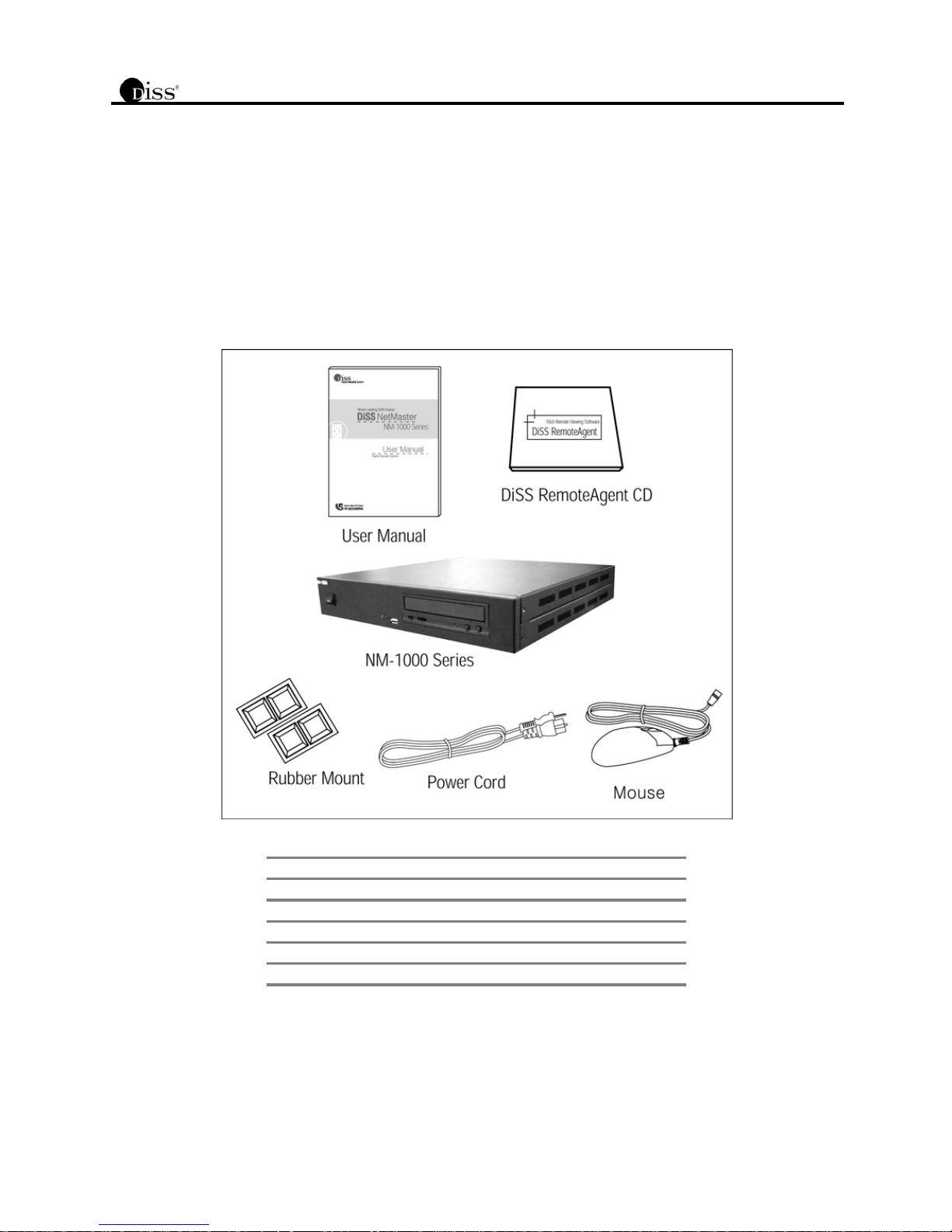
1. SYSTEM STRUCTURE
The following components are supplied with the NetMaster series. Check your NetMaster system and its accessories are securely
packed. As you unpack your system, please be sure to check all of the following items are included.
Carefully inspect each component to make sure nothing is missing or damaged. When any of these items is missing or damaged, notify
your dealer immediately. Keep the packing utilities for moving or storage purposes afterwards.
1.1 NM-1000 Series
Qty
Contents
1
User Manual
1 DiSS RemoteAgent CD
1 Power Cord
1 Rubber Mount
1 Mouse
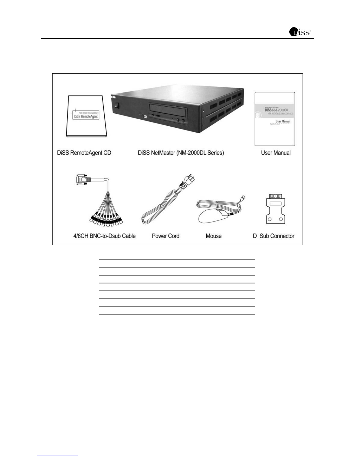
2
1.2 NM-2000DL Series
Qty
Contents
1
User Manual
1 Power Cord
1 Mouse
1 D-sub Connector
1 DiSS RemoteAgent CD
1 4/8CH BNC-to-D-sub Cable (Select by Max Channel Number)
3
2. System Configuration
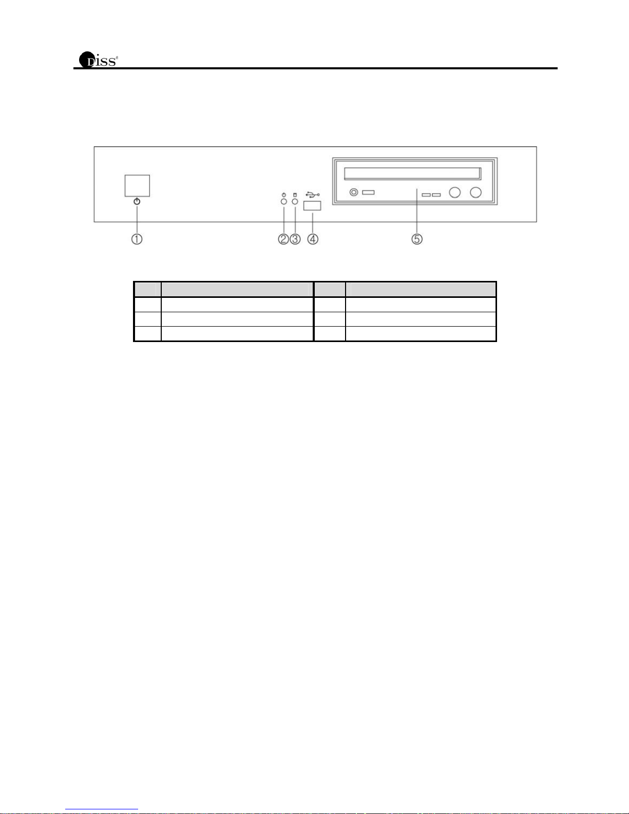
2.1 NM-1000 Series Front Panel
NM-1004/1008
No. Functions No. Functions
1 Power Button 4 USB Port
2 Power LED 5 CD-RW / DVD-RAM (Option)
3 HDD LED
2.1.1. Power Button
Press the power button after connecting power cord.
2.1.2. Power LED
Shows the power is on.
2.1.3. HDD LED
Shows data is either being read or written in HDD.
2.1.4. USB Port
This internal USB port is used to connect the USB to the system. USB port is composed in back panel of the system also.
2.1.5. CD-RW / DVD-RAM (Option)
It is possible to mount CD-RW / DVD-RAM as backup or removable HDD as data storage.
4
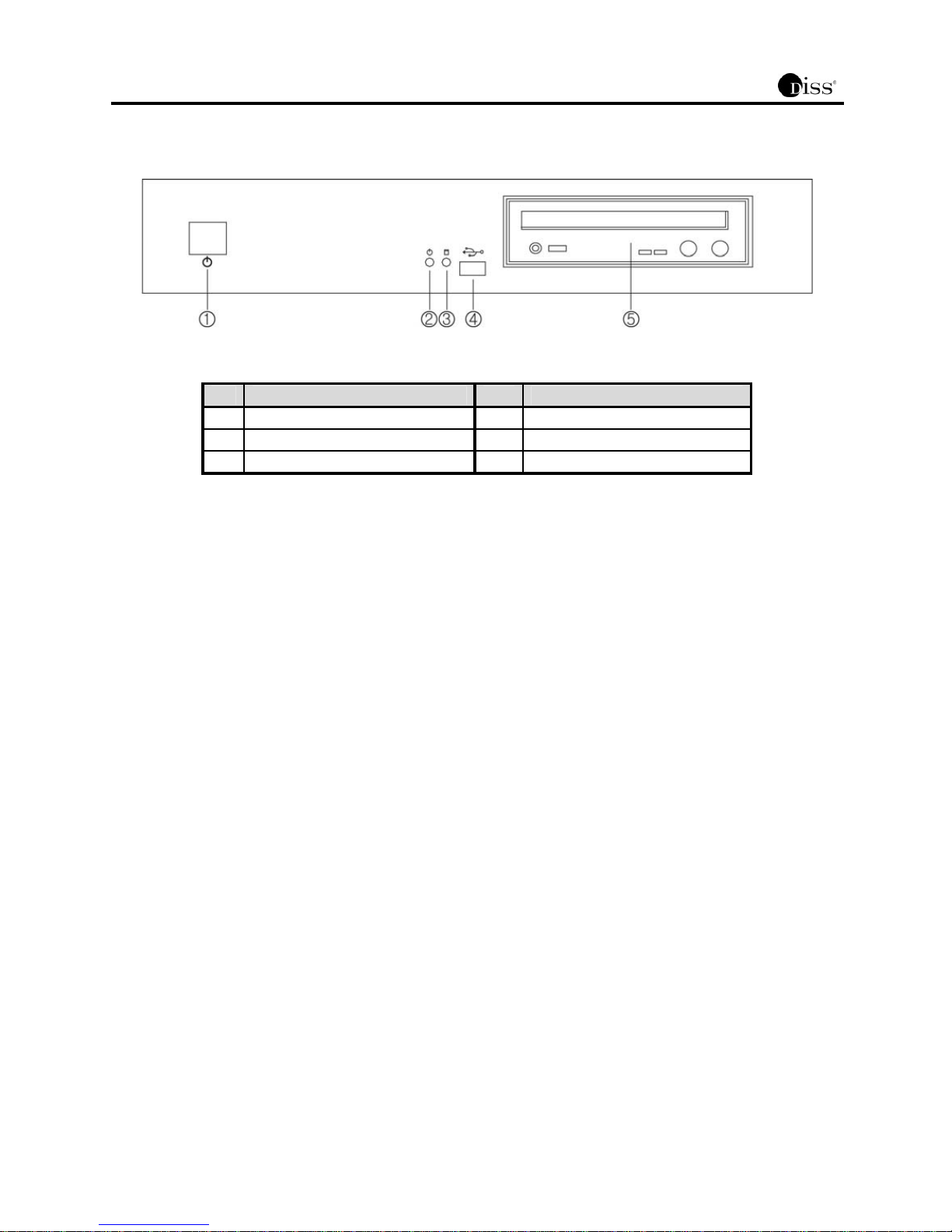
2.2 NM-2000DL Series Front Panel
NM-2004DL/2008DL/2016DL
No. Functions No. Functions
1 Power Button 4 USB Port
2 Power LED 5 CD-RW / DVD-RAM (Option)
3 HDD LED
2.2.1. Power Button
Press the power button after connecting power cord.
2.2.2. Power LED
Shows the power is on.
2.2.3. HDD LED
Shows data is either being read or written in HDD.
2.2.4. USB Port
This internal USB port is used to connect the USB to the system. USB port is composed in back panel of the system also.
2.2.5. CD-RW / DVD-RAM (Option)
It is possible to mount CD-RW / DVD-RAM as backup or removable HDD as data storage.
5
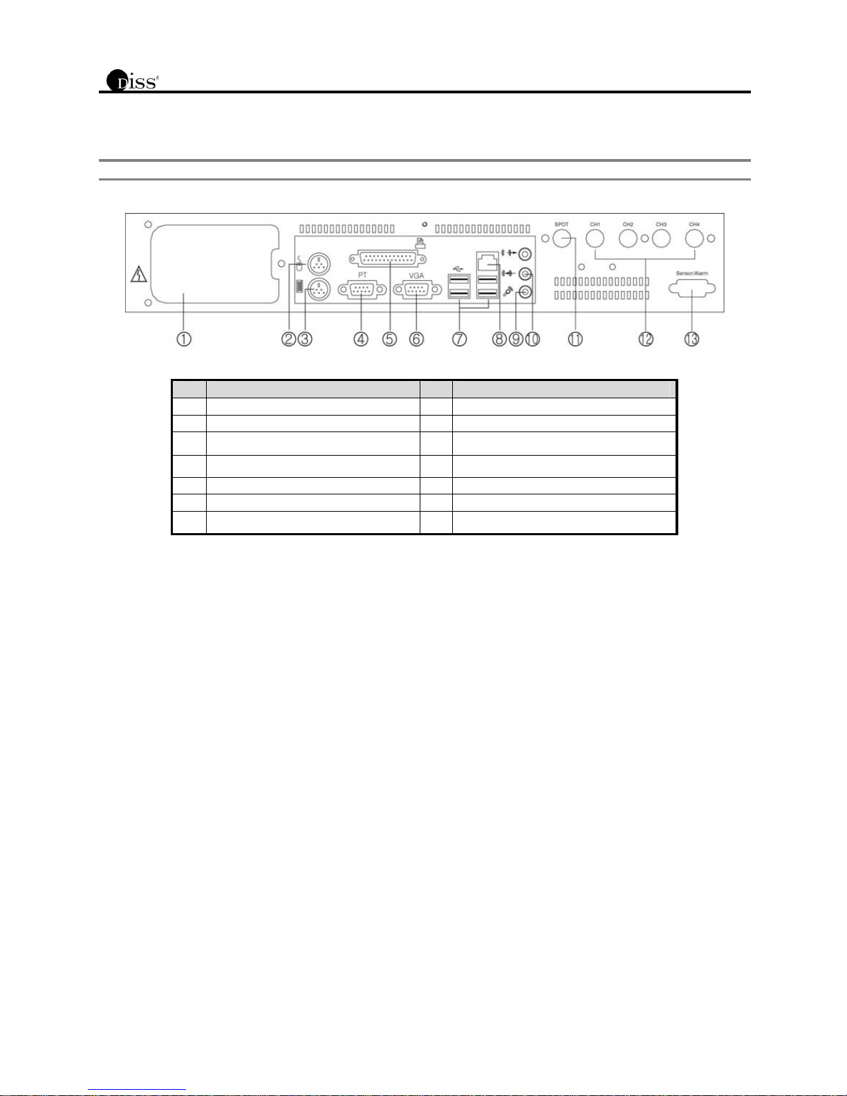
2.3 NM-1000 Series Back Panel
Note
Composition differs according to system model. (NM-1004/1008)
No. Functions No. Functions
1 Power Connection Circuit 8 LAN Port
2 Mouse Port 9 Mic input
3 Keyboard Port 10 Speaker Output
4 PTZ Controller Port 11 Spot Monitor Output (BNC Jack)
5 Printer Port 12 Camera Image Input (BNC Jack)
6 PC Monitor Output 13 Sensor / Alarm Connection
7 USB Port

6
2.4 NM-2000DL Series Back Panel
Note
Composition differs according to system model. (NM-2004DL/2008DL/2016DL)
No. Functions No. Functions
1 Power Selection Switch 9 LAN Port
2 Power Connection Circuit 10 Speaker Output
3 Mouse Port 11 Mic Input
4 Keyboard Port 12 Alarm Input/Output Port
5 USB Port 13 Spot Monitor Output / RCA Jack
6 PTZ Controller Port / RS-232C (COM1)
7 Printer Port
8 PC Monitor Output (VGA)
14
Image Input / D_Sub
NM-2004DL: 4ch 1ea
NM-2008DL: 8ch 1ea
NM-2016DL: 8ch 2ea
7
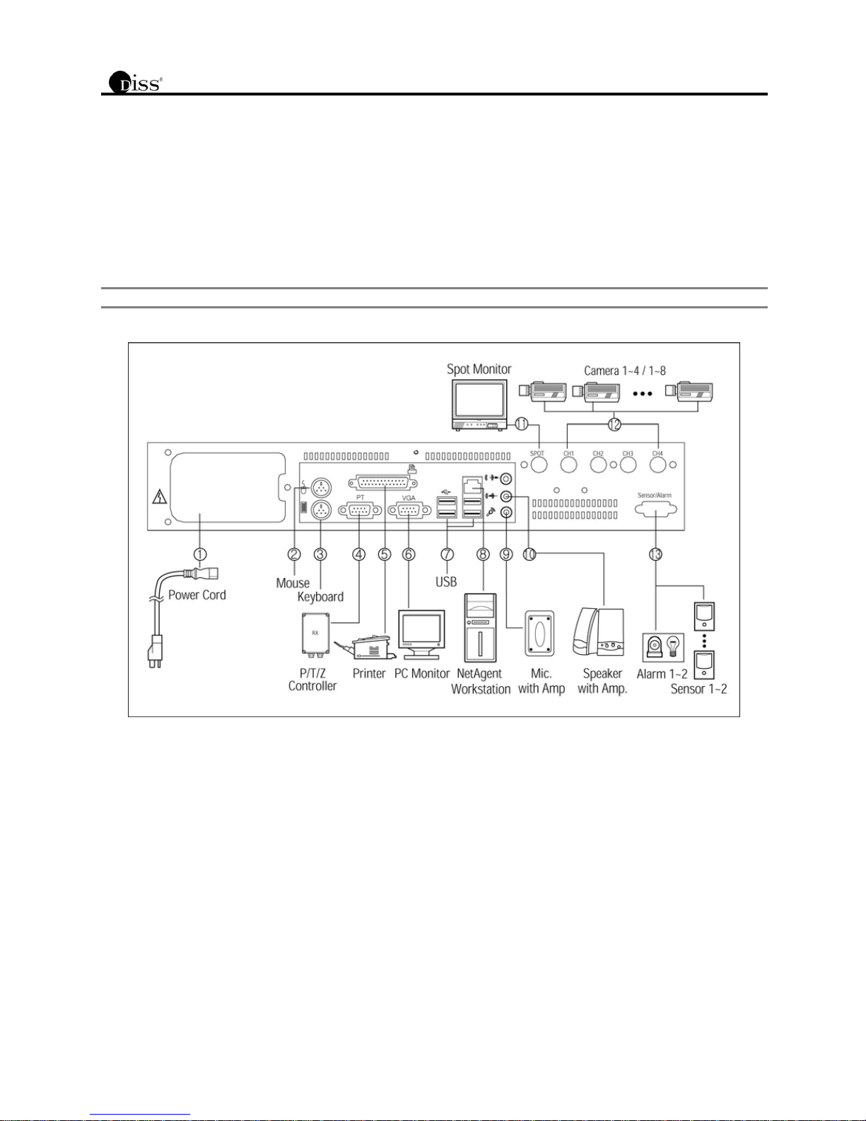
3. INSTALLATION
3.1 NM-1000 Series Installation
This section describes how to hook up NetMaster to peripheral devices. Connect the peripheral devices by referring to below picture.
Install NetMaster series in flat surface, and use rubber mount if needed. Install on the rack in case of using 19 inch, and leave
2.5~3U(1U=1.75 inch or 4.45 cm) space for spare room.
Note
Install in well-ventilated places for system heat prevention.

8
3.1.1. Power Connection Circuit
Connect the power cord enclosed.
Note
Before connecting the power, convert the power switch, AC110V ~ 120V ->115, AC220V~240V->230V, depending on the
power voltage on the power socket.
3.1.2. Mouse Port
Connect the mouse enclosed.
3.1.3. Keyboard Port
Keyboard can be connected. (Option)
3.1.4. PTZ Controller Port
When PTZ controller is connected as 1:1, it will be connected directly to RS-232C. Normally use RS-422 or RS-485, when several PTZ
controllers are connected at once. To do this, an adapter (option) is required to transfer RS-422/485 signal to RS-232C signal.
3.1.5. Printer Port
To print the searched image in best quality, high quality color printer and exclusive paper are recommended to use. To install printer
driver, refer to “Viewer->Other Setting->Add Printer”.
3.1.6. PC Monitor Output
Connect PC monitor to view the image output. NM-1000 series supports both PC monitor and Spot monitor. When the analogue
monitor is connected to RCA Jack, the part of analogue image is always outputted except for the various user interface shown in the PC
monitor. The screen mode of the spot monitor output is always full screen, and is controlled independently with the PC monitor. Refer to
“Setting Customized Functions-> Select Recording” for detailed information.
3.1.7. USB Port
Connect exterior CD-RW driver of USB interface. Only approved USB CD-RW models by manufacturer can be used.
3.1.8. LAN Port
In case of remote monitoring, connect the network to LAN (Local Area Network), Internet, or exclusive line of TCP/IP basis. IP address
should be fixed, and dynamic IP address allocated from DHCP cannot be used.
3.1.9. Mic Input
Input voice is synchronized in image of the channel 1. When the voice signal is line level, connect to Line In jack at the left of the Mic
Input jack.
3.1.10. Speaker Output
The output signal is line level. To expand the output signal, there is a need for amp in the middle.
3.1.11. Spot Monitor Output
When the analogue monitor is connected to BNC Jack, the part of analogue image is always outputted except for the various user
interface shown in the PC monitor. The screen mode of the spot monitor output is always full screen, and is controlled independently
with the PC monitor.

9
3.1.12. Image Input
Image input has analogue composite signal and can be set to NTSC or PAL, according to the requirement of the user during product
order. Be sure to match the type of camera to be corresponding with the system. To get good quality image, check the power of the
whole system and the safety of the ground construction. Also, adjust the lightening and focus or iris of the camera properly.
Note
The camera image cannot be recorded properly when the PTZ control signal is mixed with camera signal. In this case,
connect after separating the control signal.
3.1.13. Sensor Input / Alarm Output Port
To use sensor input and alarm output, alarm I/O Terminal (Option) would be needed. Connect cable of terminal to alarm output port, and
then each sensor and wire of alarm devices to corresponding terminal. Sensor and alarm devices can be connected up to max. 4 each.
Note
Sensor alarm is activated by relay switch. It can be connected to either N/O (Normal open) or N/C (Normal Close) type and
the user have to set the sensor according to each of them. Also to recognize the sensor input, the point of contact has to be
closed for at least 0.5secs and the power in the rated current must not be excess in the relay.
10
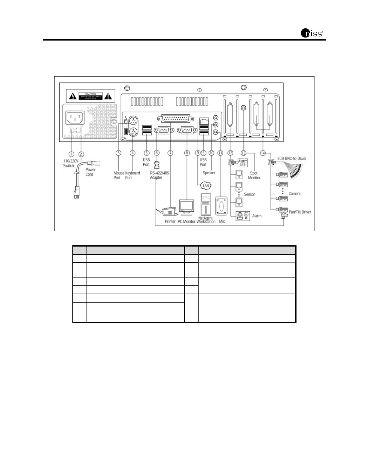
3.2 NM-2000DL Series Installation
No. Functions No. Functions
1 Power Selection Switch 9 LAN Port
2 Power Connection Circuit 10 Speaker Output
3 Mouse Port 11 Mic Input
4 Keyboard Port 12 Alarm Input/Output Port
5 USB Port 13 Spot Monitor Output / RCA Jack
6 PTZ Controller Port / RS-232C (COM1)
7 Printer Port
8 PC Monitor Output (VGA)
14
Video Input / D_Sub
NM-2004DL: 4ch 1ea
NM-2008DL: 8ch 1ea
NM-2016DL: 8ch 2ea

11
3.2.1. Power Selection Switch
Select the power between AC 110V and 220V.
Note
Before connecting the power, convert the power switch, AC110V ~ 120V ->110, AC220V~240V->220V, depending on the
power voltage on the power socket.
3.2.2. Power Connection Circuit
Connect the power cord enclosed.
3.2.3. Mouse Port
Connect the mouse enclosed.
3.2.4. Keyboard Port
Keyboard can be connected (Option).
3.2.5. USB Port
Connect exterior CD-RW driver of USB interface. Only approved USB CD-RW models by manufacturer can be used.
3.2.6. PTZ Controller Port / RS-232C
When PTZ controller is connected as 1:1, it will be connected directly to RS-232C. Normally use RS422 or RS-485, when several PTZ
controllers are connected at once. To do this, an adapter (option) is required to transfer RS-422/485 signal to RS-232C signal.
3.2.7. Printer Port
High quality color printer and appropriate paper type are required to print at highest quality. Refer to “Viewer->Other Setting” for
information on corresponding printer drive install.
3.2.8. PC Monitor Output
NM-2000DL Series supports both PC and spot monitor. Connect the analog TV monitor to spot monitor output, and the camera images
of the selected channels will be displayed in sequence. Spot monitor output is always displayed as full screen, and is independently
controlled. For more detailed information, refer to “Setting Customized Functions-> Select Recording.”
3.2.9. LAN Port
In case of remote monitoring, connect the RJ-45 jack in LAN cable. Network has to be LAN (Local Area Network), Internet, or exclusive
line of TCP/IP basis 10/100BASE-TX Ethernet. Connect to network (Internet, LAN) for remote monitoring using Agent series remote
software. The IP address must be fixed and the dynamic IP address allocated by DHCP cannot be used. Contact your dealer or
network supervisor if you need any assistance.
3.2.10. Speaker Output / Line Out
The output signal is line level. To expand the output signal, there is a need for amp in the middle.
3.2.11. Mic Input
1-Channel voice recording is possible in NM-2000DL Series, and the recorded voice is synchronized in the channel 1. Connect the mic
signal for voice recording in the mic input jack. When voice signal is line level, then connect to Line In jack placed in the left of the mic
input jack. Also, connect with the speaker to listen to the replay of recorded voice. Output signal is line level. Therefore, to amplify the
output signal, amp for speaker is necessary. Refer to “Viewer->Other Settings” for volume control.

12
3.2.12. Alarm Input/Output Port
Alarm I/O Terminal, which is an option, is needed to use the sensor input and alarm output. Connect the terminal’s cable to the alarm
input/output port. Then connect each sensor and alarm wiring to the corresponding terminal port. Sensor and alarm devices can be
connected at maximum 4 for both.
Note
Sensor and alarm are activated by relay switch. It can be connected to either N/O (Normal Open) or N/C (Normal Close)
type and the user has to set the sensor according to each of them. Also to recognize the sensor input, the point of contact
has to be closed for at least 0.5 seconds and the power in the rated current must not be excess in the relay.
3.2.13. Image Input / D_Sub
Connect the wirings of various alarm equipment in Alarm I/O Terminal, which is controlled by relay output or sensor of dry contact input.
Connect the plug of BNC cable to recording camera. In case of NM-2004DL, connect 1~4 channel cameras to the BNC Jack of 4ch
BNC-to-D_Sub. In case of NM-2008DL, connect 1~8 cameras to the BNC Jack of 8ch BNC-to- D_Sub. In case of NM-2016DL, connect
1~16 cameras using 2 cables of 8ch BNC-to-Dub.
NetMaster is compatible with PAL or NTSC camera. To get high quality image, check the power of the whole system and the safety of
the ground construction. Also, adjust the lightening and focus or iris of the camera properly.
Note
The camera image cannot be recorded properly when the PTZ control signal is mixed with camera signal. In this case,
connect after separating the control signal.
3.2.14. Spot Monitor Output/ RCA Jack
When the analogue monitor is connected to RCA Jack, the part of analogue image is always outputted except for the various user
interface shown in the PC monitor. The screen mode of the spot monitor output is always full screen, and is controlled independently
with the PC monitor.
13
4. OPERATIONS OF NetMaster
4.1 System Operations
Power Connection
Check the connection of the peripheral device of the system and connect the power.
When the power cord of the NetMaster is connected, system program will start.
To end the system, complete the booting and press the power button of the front
panel. When the user presses the power button for too long, the power of the product
will be completely blocked and it will start Auto-Recovery while booting.
Start Program
The main program will start right away when the power of the NetMaster comes in.
To use the buttons in the main screen, log in as the administrator user. Input
administrator ID and password by clicking [
] button located at the right bottom of
the main screen.
Administrator’s ID is set as “admin” when logging in for the first time, and the password is
not set. Refer to “Setting Customized Functions” for more detailed information.
Menu buttons cannot be used after logging out when [
] button is pressed.
Connect System Peripheral Device
When remote transmission and sensor is functioning well, each button shown in the
picture will activate. (Refer to "Screen Layout” for more detailed information)
Display Division Rotation
By pressing this button, the screen automatically alternates on selected screen-split.
When selected in 1-channel, then depending on the time setting, automatically
alternates by 1-channel, and when selected in 8-channels, according to the time
setting, the screen alternates by 8-channels.
Split Screen Mode
The current recording screen can be seen in several screens (4, 6, 9, 10, 13, 16
screens) or by only one screen. Whenever the user presses each button, the screen
will change to 1, 4, 6, 9, 10, 13, 16 screen.
14
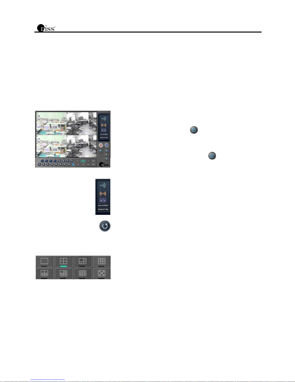
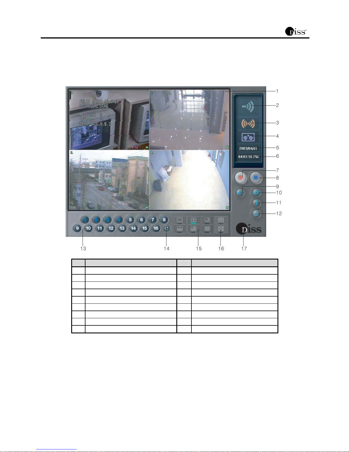
4.2 Screen L ayout
The screen layout of NetMaster is user-friendly to allow even novice users to easily learn and use the system. The following is the
layout of the NetMaster main screen.
No. Name No. Name
1 Current Recording Screen 10 Start Viewer
2 Transmission Status Indicator 11 Setup
3 Sensor Indicator 12 Administrator Login
4 Recording Status Indicator 13 Channel
5 Date 14 Display Division Rotation
6 Time 15 Display Mode/Split Screen Mode
7 Start Recording 16 Full Screen Mode
8 Stop Recording 17 NetMaster Info
9 Camera Control
15
4.3 Detail Functions
The following are the functions for each button. User login is required to use these buttons.
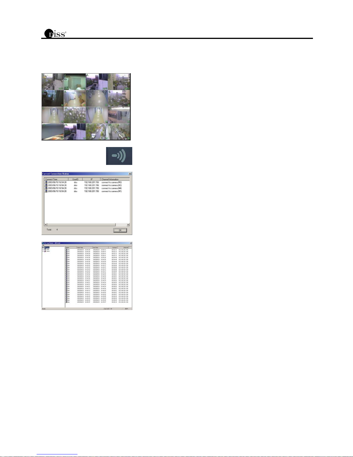
Current Recording Screen
Displays the image of connected camera or recorded images. In case the camera is
not connected, the vacant screen displays the logo of the product.
Transmission Status Indicator
Transmission status indicator flashes while connecting with remote surveillance
Agent Series to indicate that it is presently transmitting.
Shows information of the connected user when the corresponding button is clicked
while the Agent Series is connected.
When the system is not connected, double click the indicator to view full connection
history, the Net Log Viewer. It shows 200 most recent histories.
16
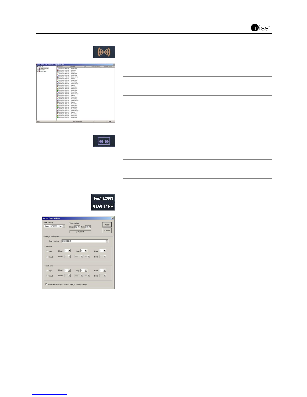
Sensor Indicator
The indicator flashes when the alarm sensor is indicated. The sensor is not operated
when “Setting Customized Functions->Sensor->Enable Sensor and Control” category
is not selected.
Note
Double click the sensor indicator with the left side of the mouse to start
the Log Viewer. The log viewer shows the list of occurred events by
date and type of the event.
Recording Status Indicator
The tape flashes to show the recording status and when it does not flash, it has been
deactivated to show that it is not recording.
Note
When all channels are in “Watch Mode,” then they are not recorded.
However, be cautious since on the screen, icon to show recording
might activate.
Date
Date is displayed in “month, date, year” format. Click this part with the mouse to
change the date/time.
To change the date and time, click on the figures that show date or time on the
NetMaster main screen and then enter proper password. Administrator can change
the setting, make any changes then click [Modify] button.
Time
Time is displayed in “hour, minute, second” format.
Click this part with the mouse to change the date/time.
Select the desired date and time. Then, click [Modify] button.
NetMaster stops recording automatically when date/time setting has been changed.
Click [Start Recording] button to start recording the images.
Daylight Saving Time
To not use the daylight saving, do not check “Automatically adjust clock for daylight
saving changes.”
To set up the daylight saving, choose “Select Nation-> USER EDIT.” Then, set up the
time and date. When the user selects the country in “Select Nation,” time and date
will change automatically depending on the country.
 Loading...