

Page 1

Preface
About SunFounder
SunFounder is a technology company focused on Raspberry Pi and Arduino open
source community development. Committed to the promotion of open source
culture, we strive to bring the fun of electronics making to people all around the
world and enable everyone to be a maker. Our products include learning kits,
development boards, robots, sensor modules and development tools. In addition
to high quality products, SunFounder also offers video tutorials to help you make
your own project. If you have interest in open source or making something cool,
welcome to join us!
About This Kit
The kit is suitable for the Raspberry Pi model B+ and Raspberry Pi 2 model B.
In this book, we will show you how to build the smart car via description,
illustrations of physical components, and schematic diagrams of circuits, in both
hardware and software respects. You may visit our website www.sunfounder.com
to download the user manual and also the related code by clicking LEARN -> Get
Tutorials and watch the videos by clicking VIDEO, or clone the code on our page
of github.com at
https://github.com/sunfounder/Sunfounder_Smart_Video_Car_Kit_for_Raspberr
yPi
If you have any questions, please send an email to [email protected]. You
can also leave a message and share your projects on our Forum.
Page 2

Contents
Introduction.......................................................................................................................................... 1
Components ........................................................................................................................................ 2
i. Acrylic Plates ....................................................................................................................... 2
i. Mechanical Fasteners ....................................................................................................... 3
ii. Drive Parts ............................................................................................................................ 4
iii. Electrical Components ..................................................................................................... 5
iv. Self-provided Parts ............................................................................................................ 8
Assembly ............................................................................................................................................... 9
i. Mechanical Assembly ....................................................................................................... 9
ii. Electrical Module Assembly ..........................................................................................30
iii. Circuit Connecting ...........................................................................................................31
Electrical Components Basics .......................................................................................................41
i. Raspberry Pi.......................................................................................................................41
ii. Step-down DC-DC Converter Module ......................................................................42
iii. Servo ....................................................................................................................................43
iv. DC Motor Driver ...............................................................................................................44
v. Servo Controller ...............................................................................................................45
vi. USB Wi-Fi Adaptor...........................................................................................................45
Software Related ...............................................................................................................................46
i. Download and Install Raspbian on a TF Card..........................................................46
ii. Get Source Code ..............................................................................................................46
iii. Basic Software Environment .........................................................................................48
iv. Calibration ..........................................................................................................................51
v. Program Analysis and Explanation .............................................................................59
Summary .............................................................................................................................................64
Page 3
1
Introduction
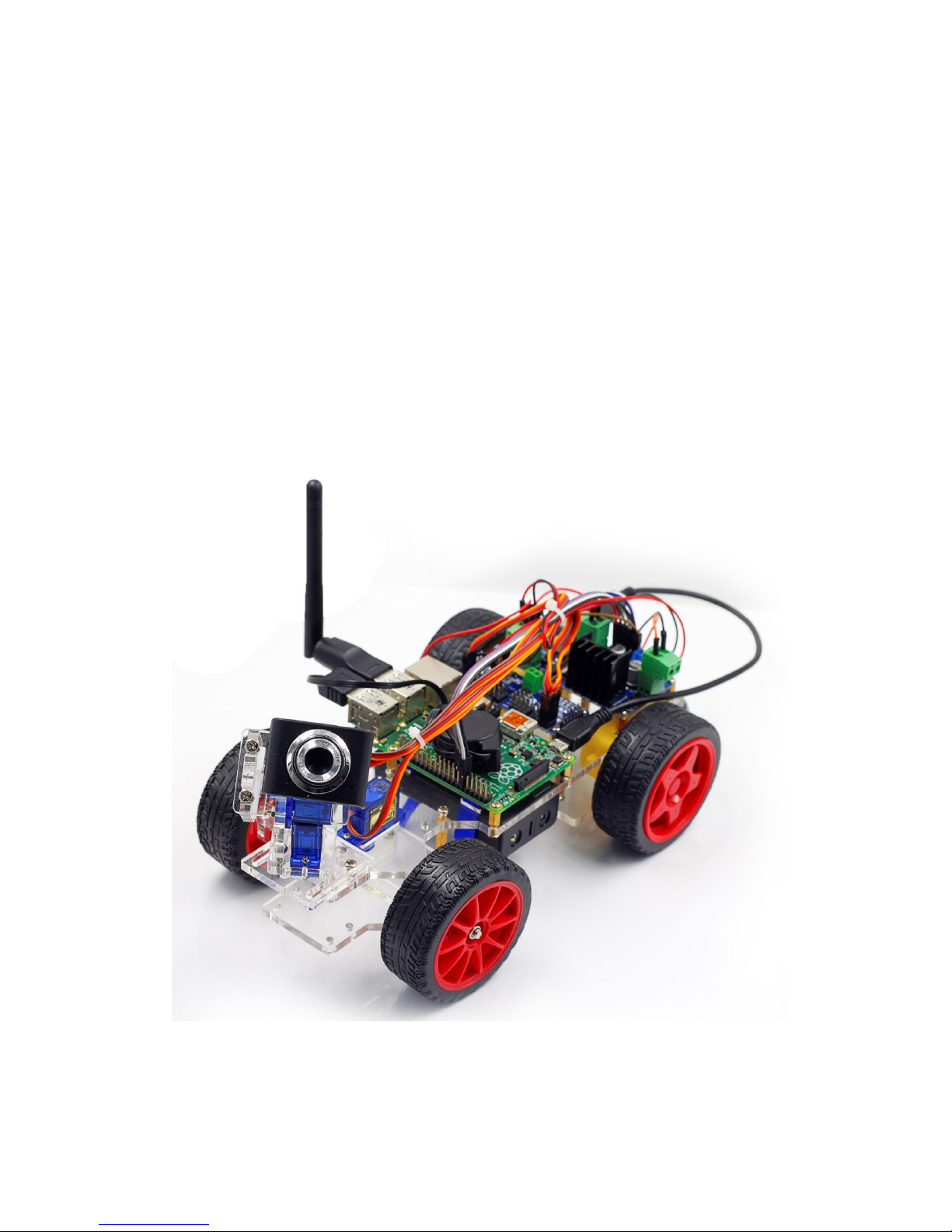
The SunFounder Smart Video Car Kit for Raspberry Pi is composed of Raspberry Pi,
step-down DC-DC converter module, USB camera, DC motor driver, and
PCA9685-based servo controller. From the perspective of software, the smart car is
of client/server (C/S) structure. The TCP server program is run on Raspberry Pi for
direct control of the car. And the video data are acquired and delivered via the open
source software MJPG-streamer in a real-time manner. The TCP client program is
run on PC to send the control command. Both the client and server programs are
developed in Python language. The smart car is developed based on the
open-source hardware Raspberry Pi and integrates the knowledge of mechanics,
electronics, and computer, thus having profound educational significance.
Page 4
2
Components
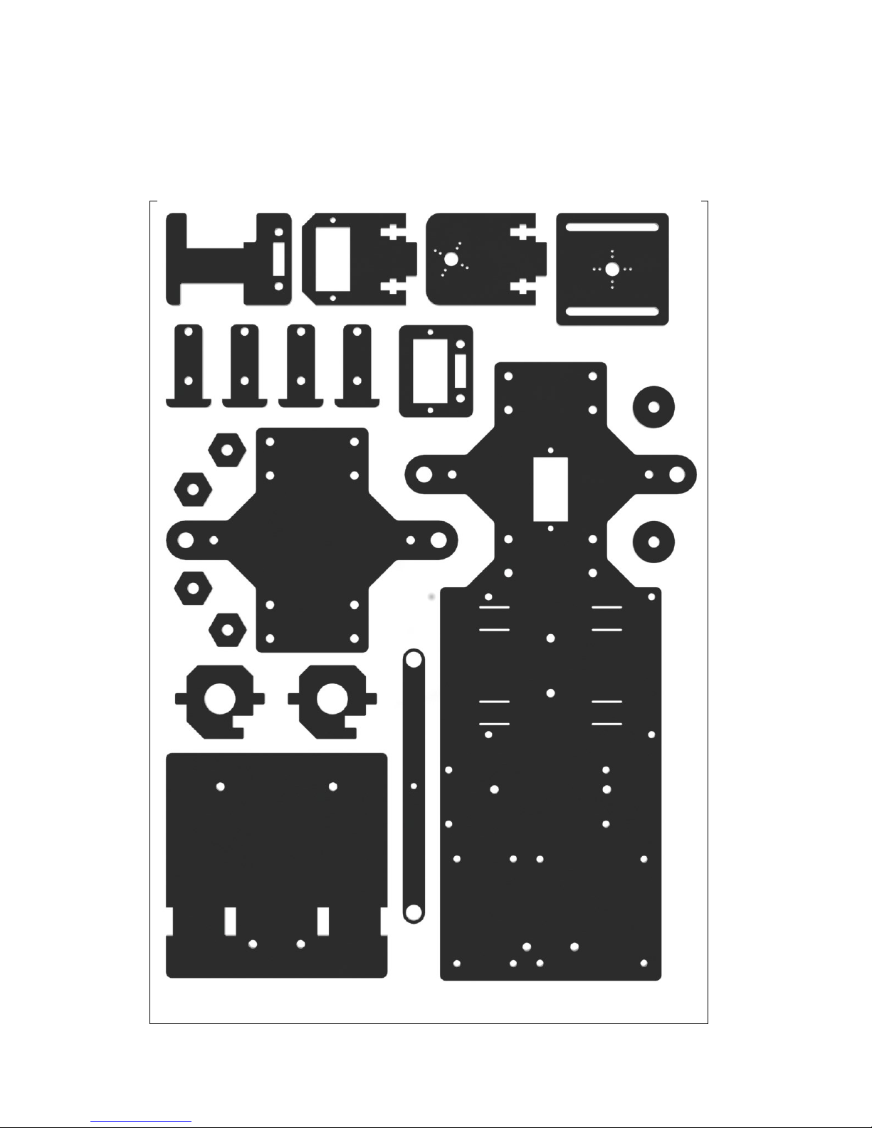
i. Acrylic Plates
Page 5
3
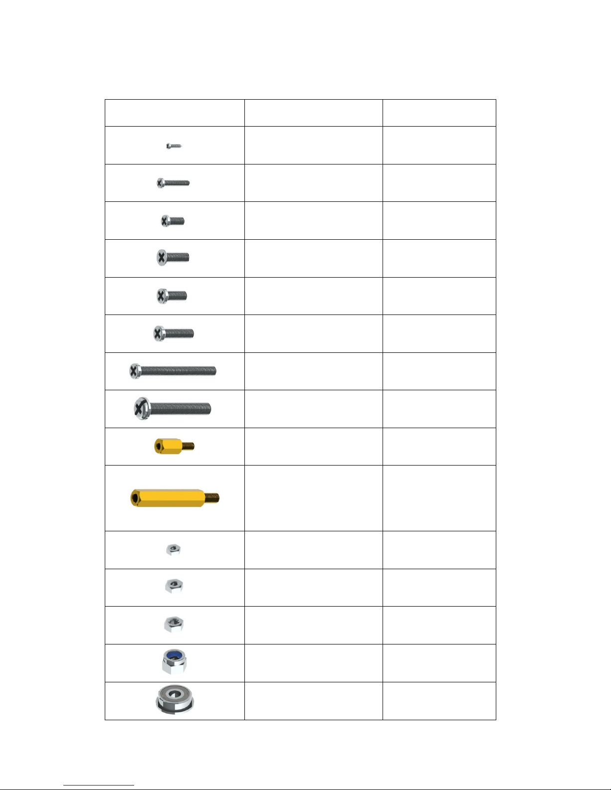
i. Mechanical Fasteners
Parts
Name
Quantity
M1.2*5 self-tapping screw
8
M2*10 screw
6
M2.5*6 screw
16
M3*10 countersunk screw
2 M3*8 screw
8
M3*12 screw
6
M3*30 screw
4
M4*25 screw
2
M2.5*8 copper pillar
16
M3*24 copper pillar
8
M2 nut
6
M2.5 nut
16
M3 nut
20
M4 self-locking nut
2
F694ZZ flange bearing
2
Page 6
4
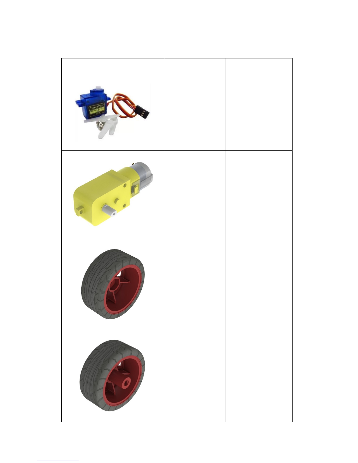
ii. Drive Parts
Parts
Name
Quantity
Tower Pro
Micro Servo
SG90
3
Gear reducer
2
Driven wheel
2
Active wheel
2
Page 7
5
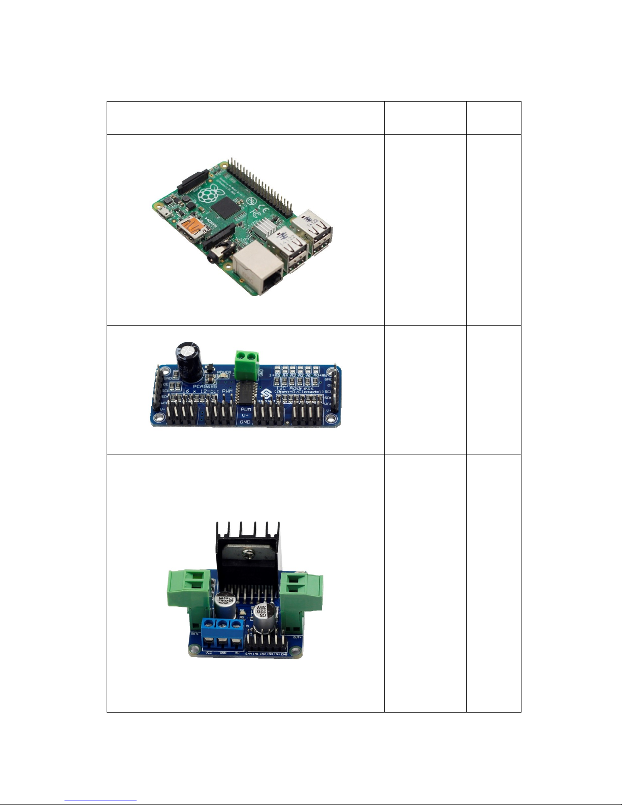
iii. Electrical Components
Parts
Name
Quantity
Raspberry Pi
Model B+
1
16-Channel
12-bit
PWM driver
(servo
controller)
1
L298N DC
motor driver
1
Page 8
6
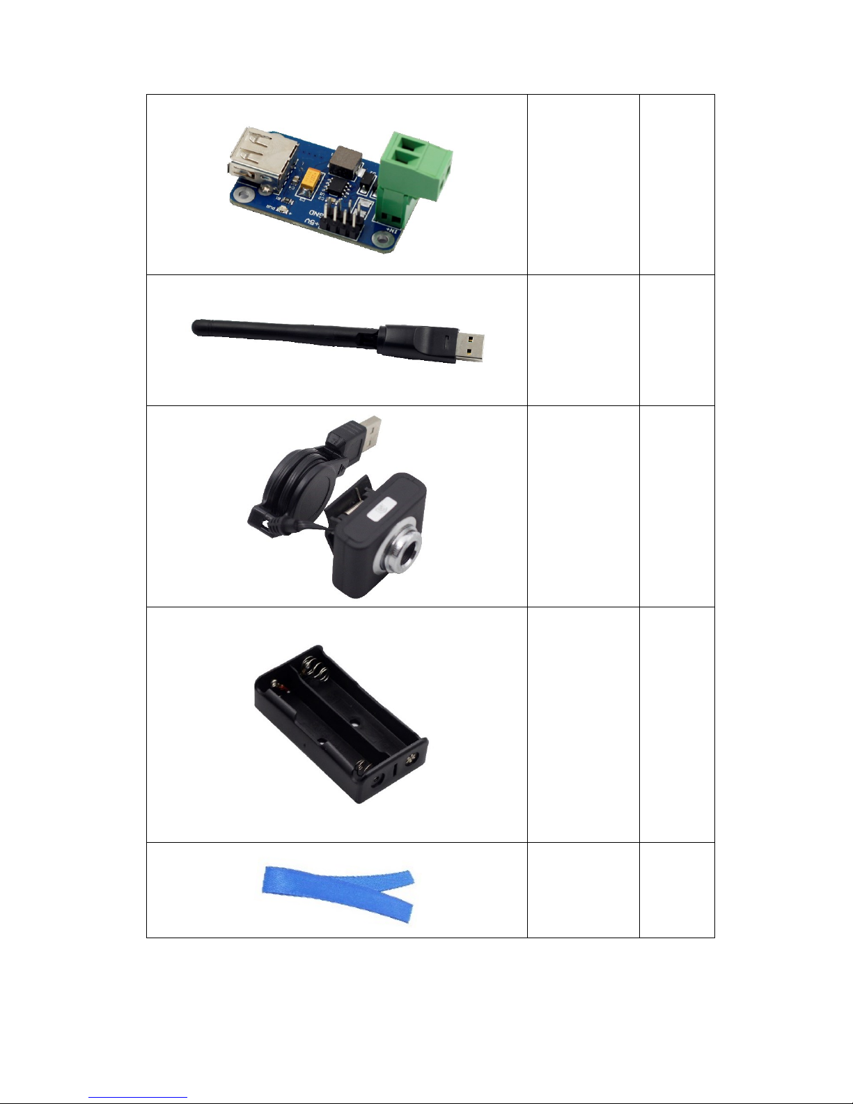
Step-down
DC-DC
converter
module
1
USB Wi-Fi
adapter
1
USB camera
1
18650*2
Battery holder
1
Ribbon
1
Page 9
7
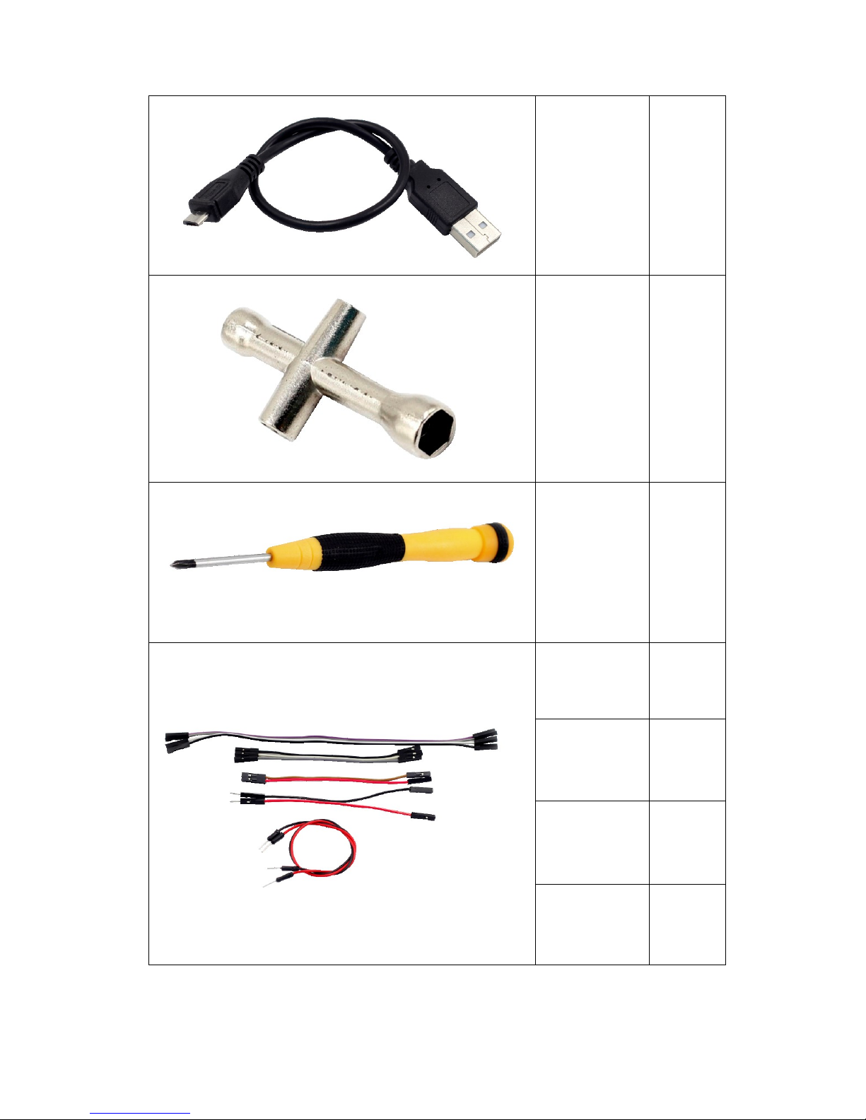
USB cable
1
Cross socket
wrench
1
Cross
screwdriver
1
20cm jumper
wire (F to F)
4
10cm jumper
wire (F to F)
5
10cm jumper
wire (M to F)
2
20cm jumper
wire (M to M)
2
Page 10
8
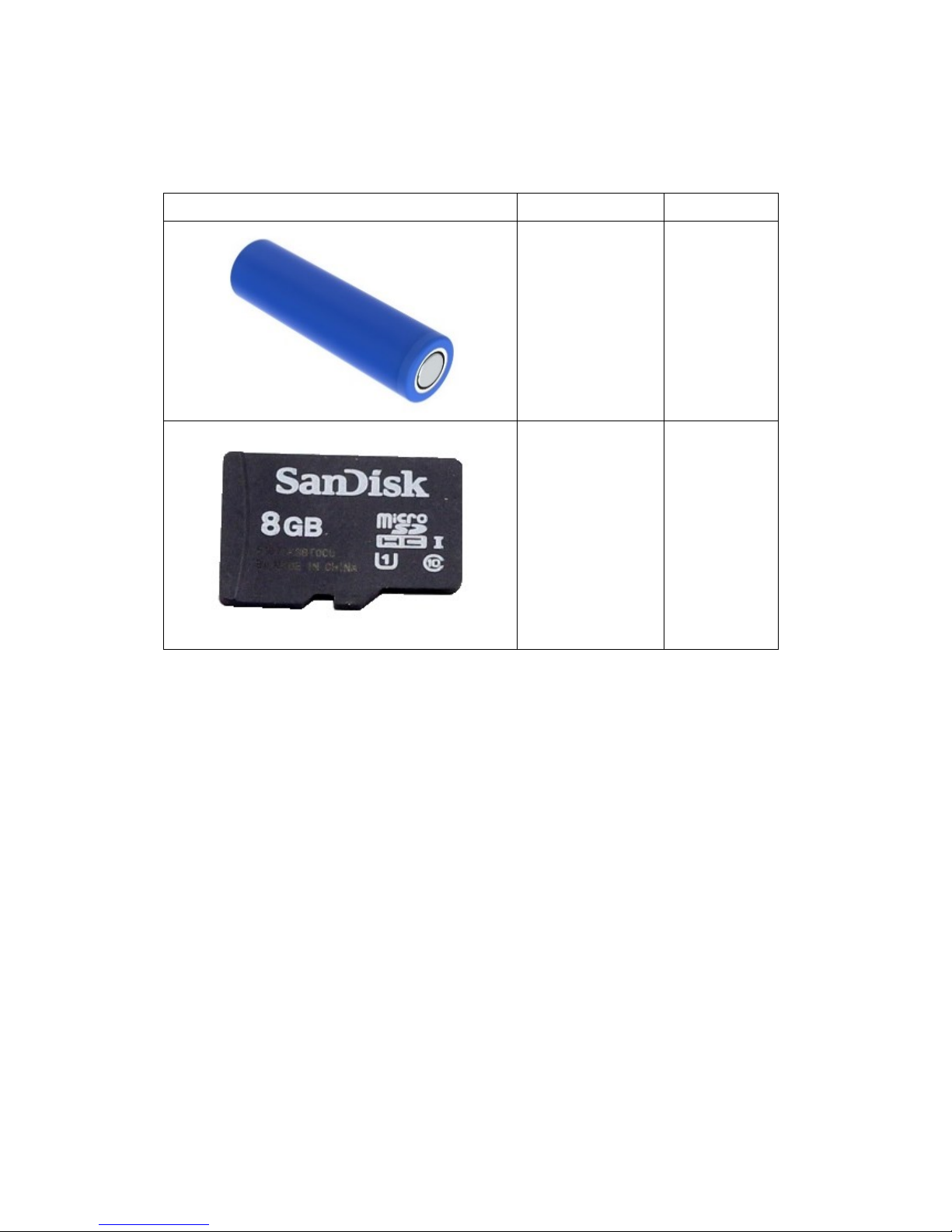
iv. Self-provided Parts
The following parts are not included in the set.
Parts
Name
Qty. Needed
18650 3.7V
rechargeable
Li-ion battery
2
TF Card
1
Page 11
9
Assembly
i. Mechanical Assembly
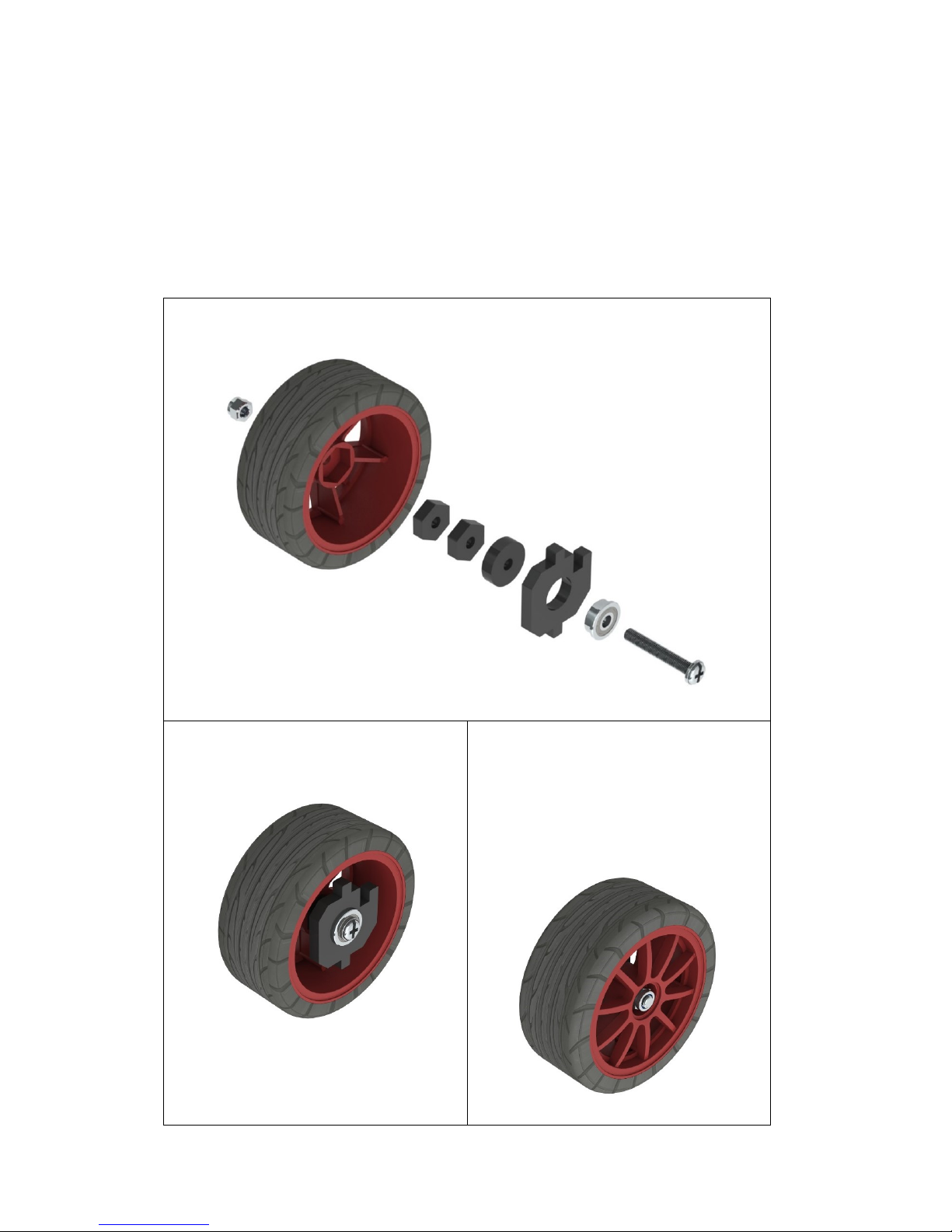
1. Car Assembly
Front Wheels
a) Fasten the F694ZZ flange bearing, driven wheel and following acrylic plates
with an M4*25 screw and an M4 self-locking nut in the way as shown below.
b) When completed, the assembly
should look like the figure below.
c) Bear in mind that DO NOT over
tighten the nut or else the wheel
cannot turn flexibly. Neither too
loose, in case the gap between the
parts is too large.
Page 12
10
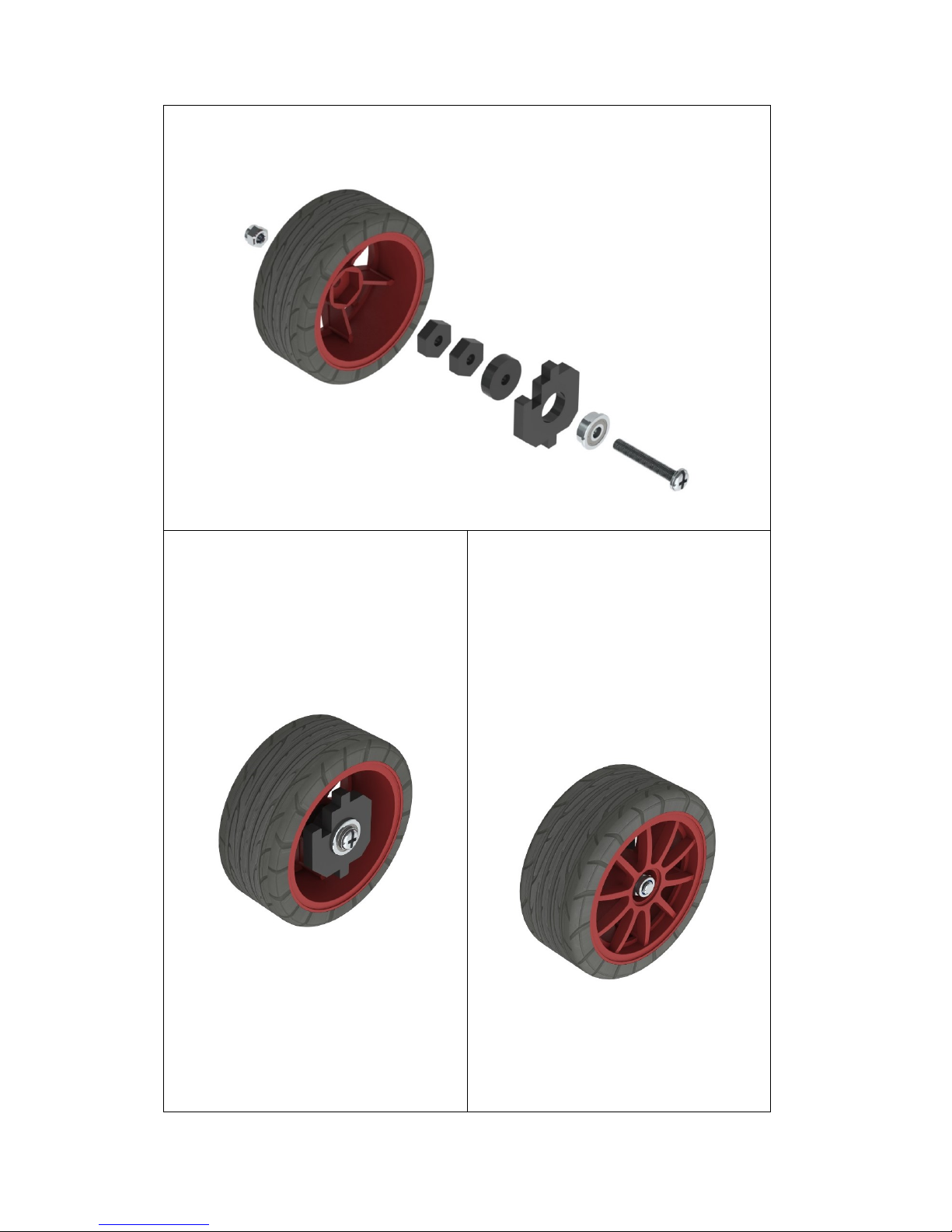
a) Fasten the F694ZZ flange bearing, driven wheel and following acrylic plates
with an M4*25 screw and an M4 self-locking nut in the way shown as below.
b) When completed, the assembly
should look like the figure below.
c) Bear in mind that DO NOT over
tighten the nut or else the wheel
cannot turn flexibly. Neither too
loose, in case the gap between the
parts is too large.
Page 13
11
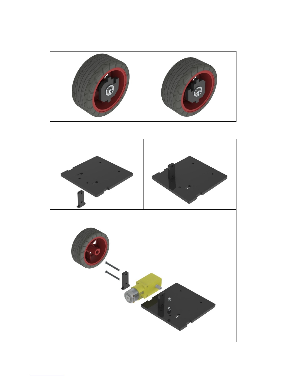
Note: The acrylic plates next to the bearing in the two wheels are of opposite faces,
as shown in the following figure.
Back Half Chassis + Rear Wheels
a) Assemble the following two acrylic
plates
b) When completed, the assembly
should look like the figure below.
c) Assemble the gear reducer, the active wheel and following acrylic plates
with two M3*30 screws and M3 nuts.
Page 14
12
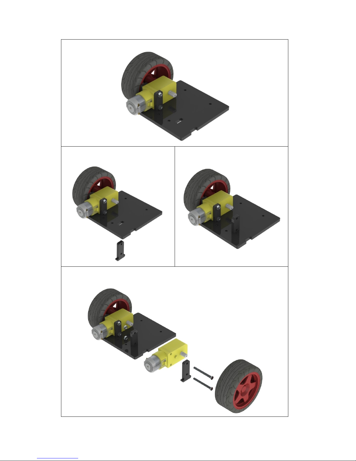
d) When completed, the assembly should look like the figure below.
a) Assemble the following two acrylic
plates
b) When completed, the assembly
should look like the figure below.
c) Assemble the gear reducer, the active wheel and the previously assembled
part with two M3*30 screws and M3 nuts.
Page 15
13
d) When completed, the assembly should look like the figure below.
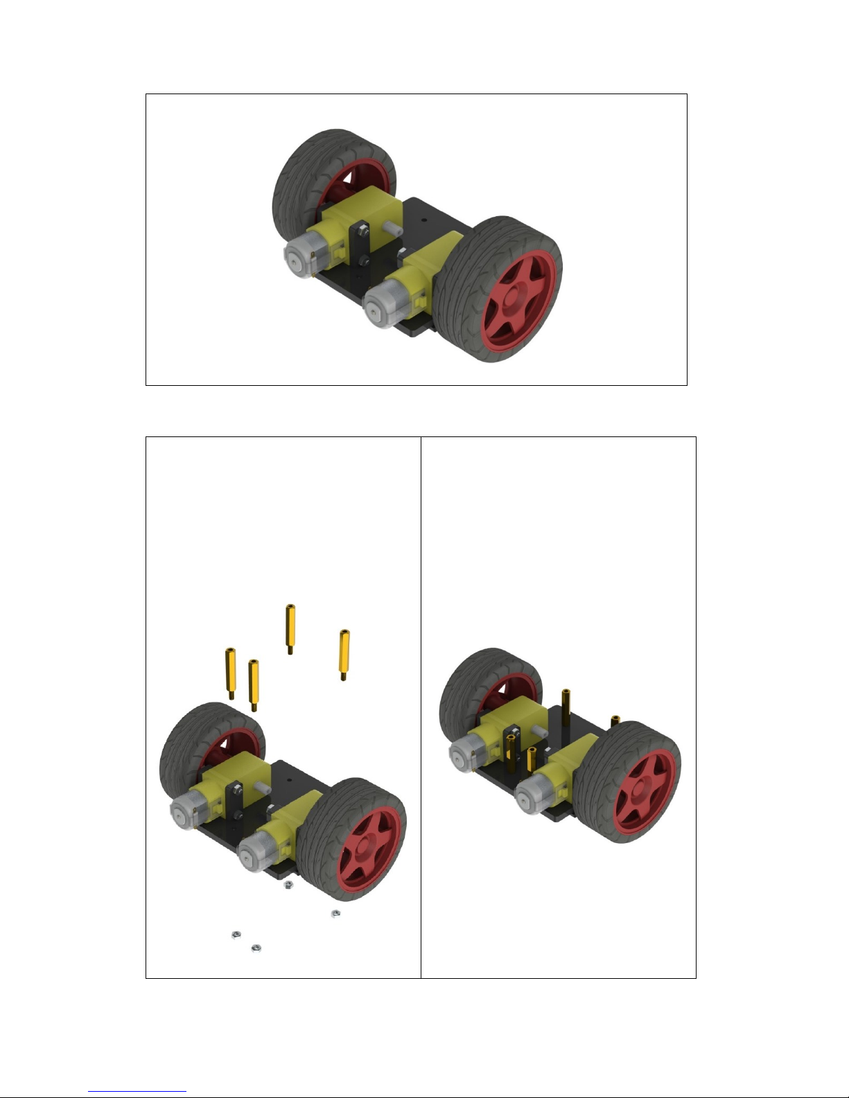
Back Half Chassis + Copper Standoffs
a) Assemble 4 M3*24 copper standoffs
and 4 M3 nuts into the acrylic plate
part as shown below.
b) When completed, the assembly
should look like the figure below.
Page 16
14
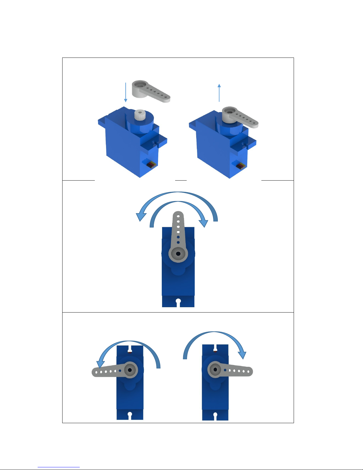
Servo Adjustment
a) The rocker arm can be placed onto and removed from the servo freely as
shown in the following figure.
b) Turn the rocker arm within an angle of about 180 degrees.
c) The rocker arm is placed in a random way at the beginning. You need to
adjust it to restrict its turning in an almost equal angle towards right and
left.
Page 17
15
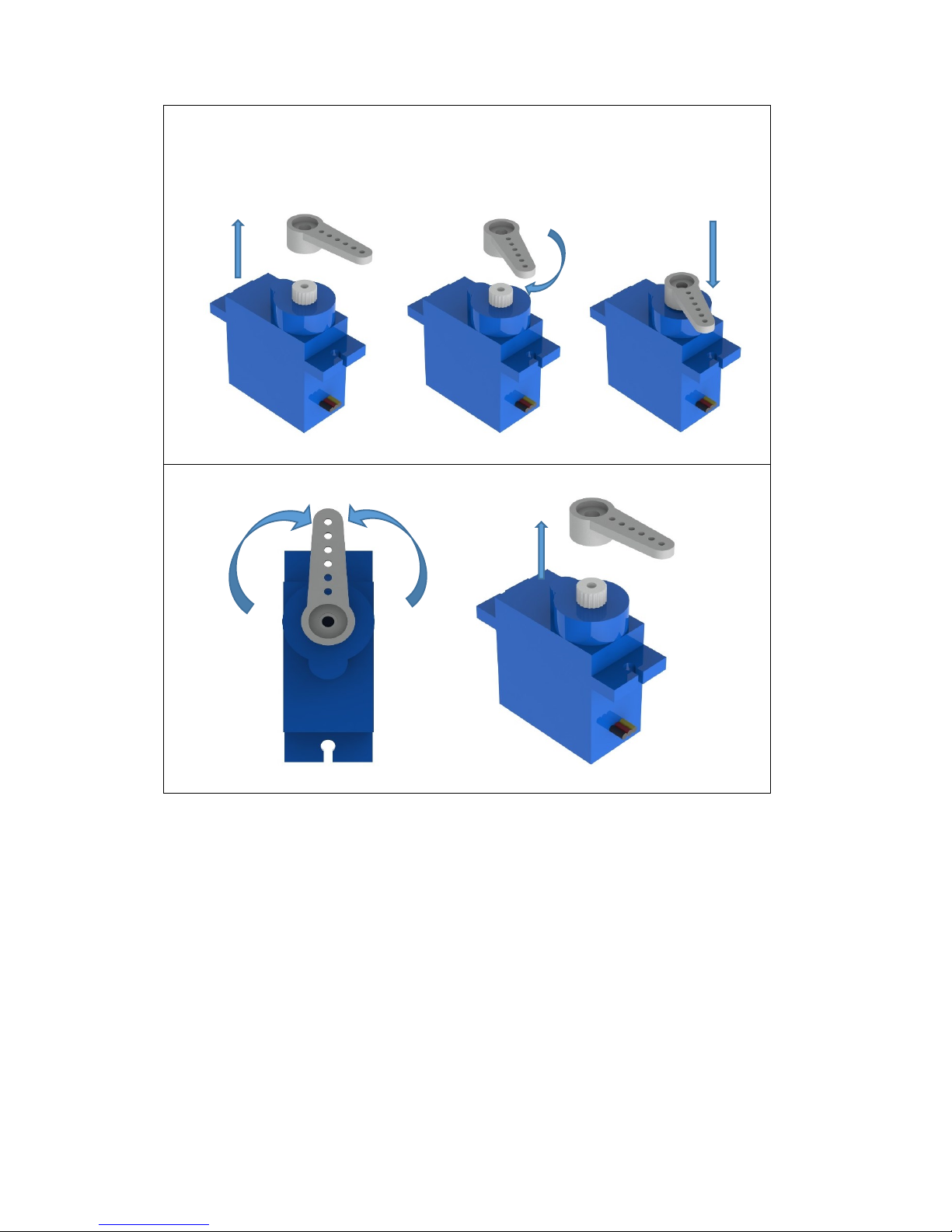
Remove the rocker arm and install it again in another angle. Turn right
and left to see whether the condition of the angle is met.
Repeat the step until the condition is met. It matters to the subsequent
installation.
d) After the adjustment, turn the rocker arm to the middle and remove it.
Note: Make sure the step is carried out for all servos and that the axis of the servos
is not moved accidentally in the subsequent installation. If the axes are moved,
adjust them again before the installation.
Page 18
16
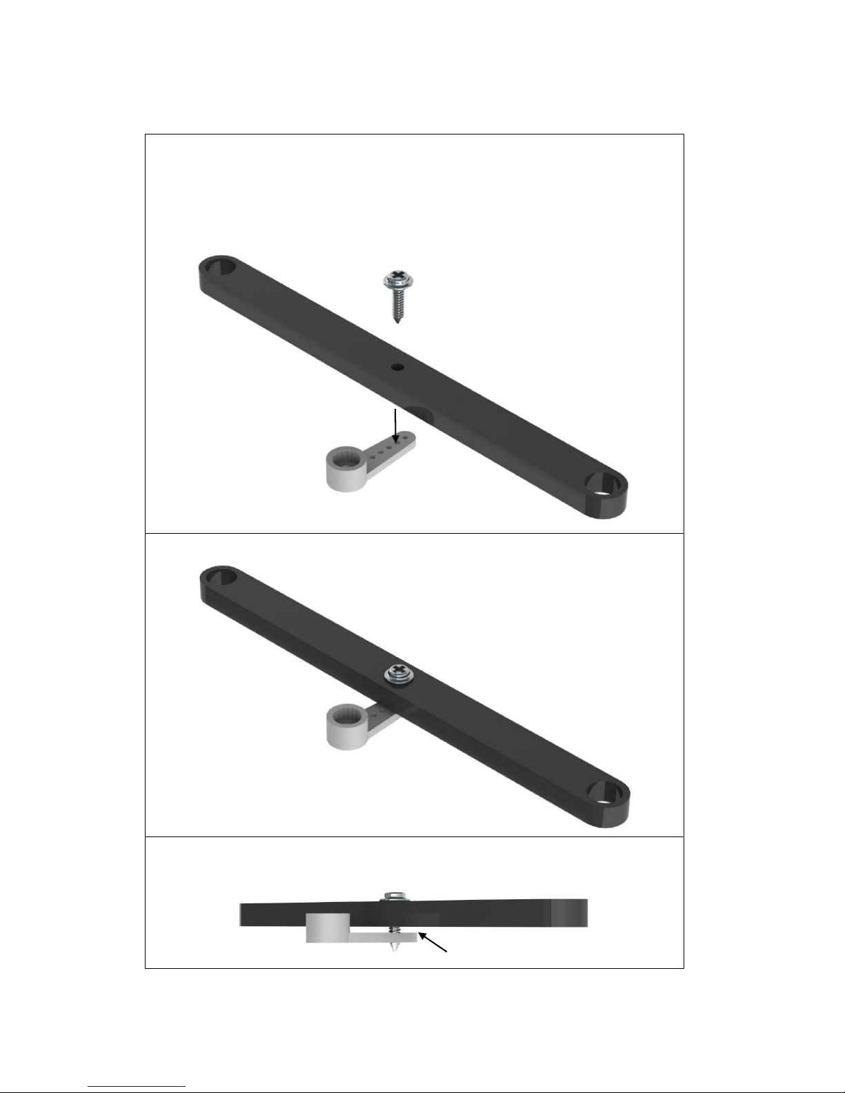
Steering Linkage + Servo Rocker Arm
a) Connect the following acrylic plate to the second hole of the rocker arm (see
the figure below) with an M2*8 self-tapping screw.
The M2*8 self-tapping screw is contained in the package of the servo; it
is one of the two longest screws.
Also the rocker arm is packaged together with the servo.
b) When completed, the assembly should look like the figure below.
Be careful not to tighten the screw too much. Keep a gap of about 1mm
between the two.
Page 19
17
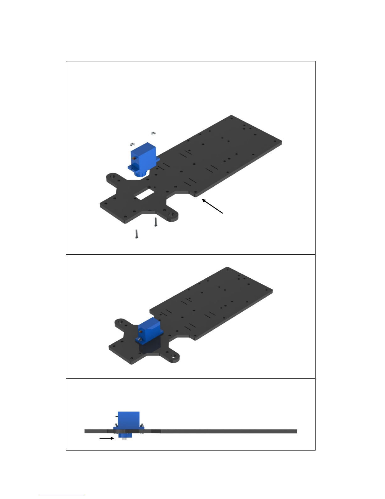
Steering Servo + Upper Plate
a) Connect the servo to the acrylic plate below with two M2*10 screws and M2
nuts.
Pay attention to the face of the plate. Refer to the small hole in the
plate as pointed by the arrow in the following figure.
b) When completed, the assembly should look like the figure below.
Note: The servo should be placed with its output shaft toward the front of the
plate (see the following figure).
Page 20
18
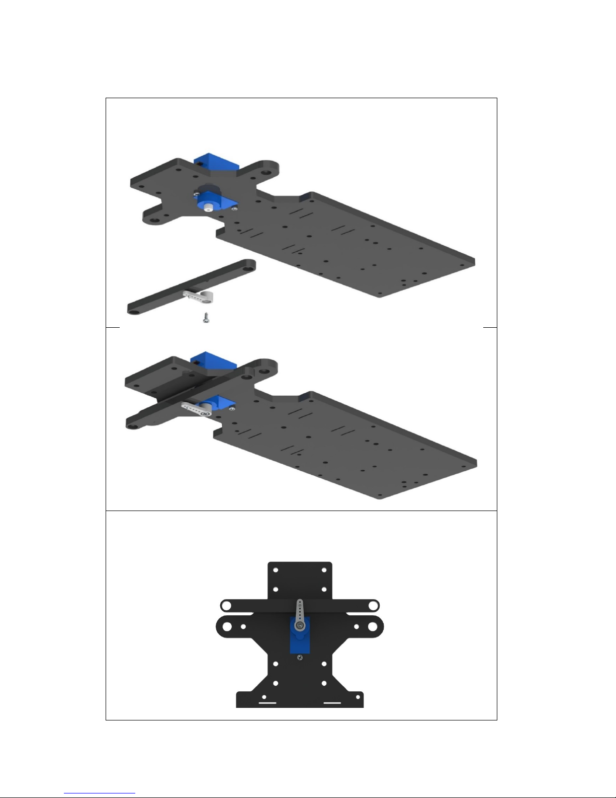
Steering Servo + Steering Linkage
a) Connect the following parts with an M2*4 screw.
The M2*4 screw is contained in the package of the servo; it is the shortest
of the screws in the package.
b) When completed, the assembly should look like the figure below.
Pay attention to the orientation during the assembly. If you find any error in
the assembly, do not try to turn the axis of the servo; instead, you should
disassemble it and then assemble the parts again.
Page 21
19
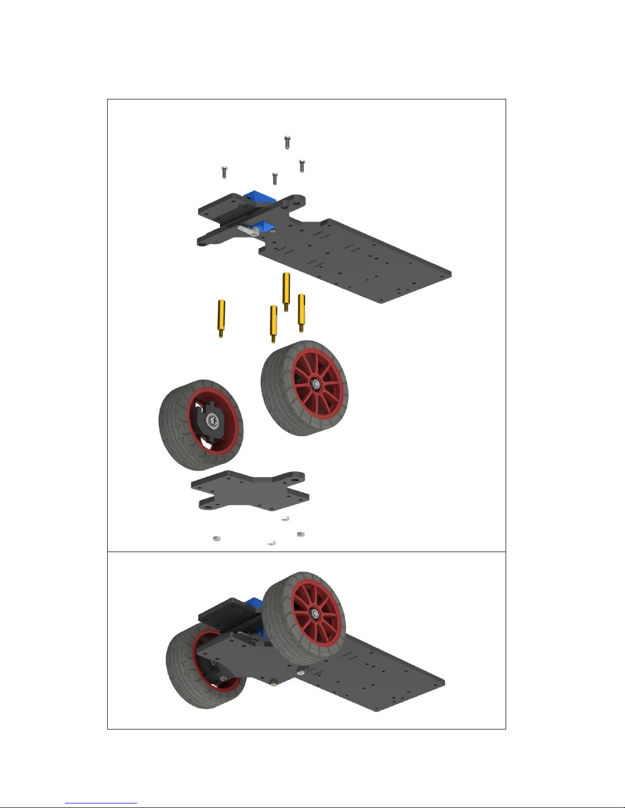
Front Chassis + Upper Plate
a) Connect the following parts and wheels with M3*8 screws, M3*24 copper
standoffs and M3 nuts, 4 for each.
b) When completed, the assembly should look like the figure below.
Page 22
20
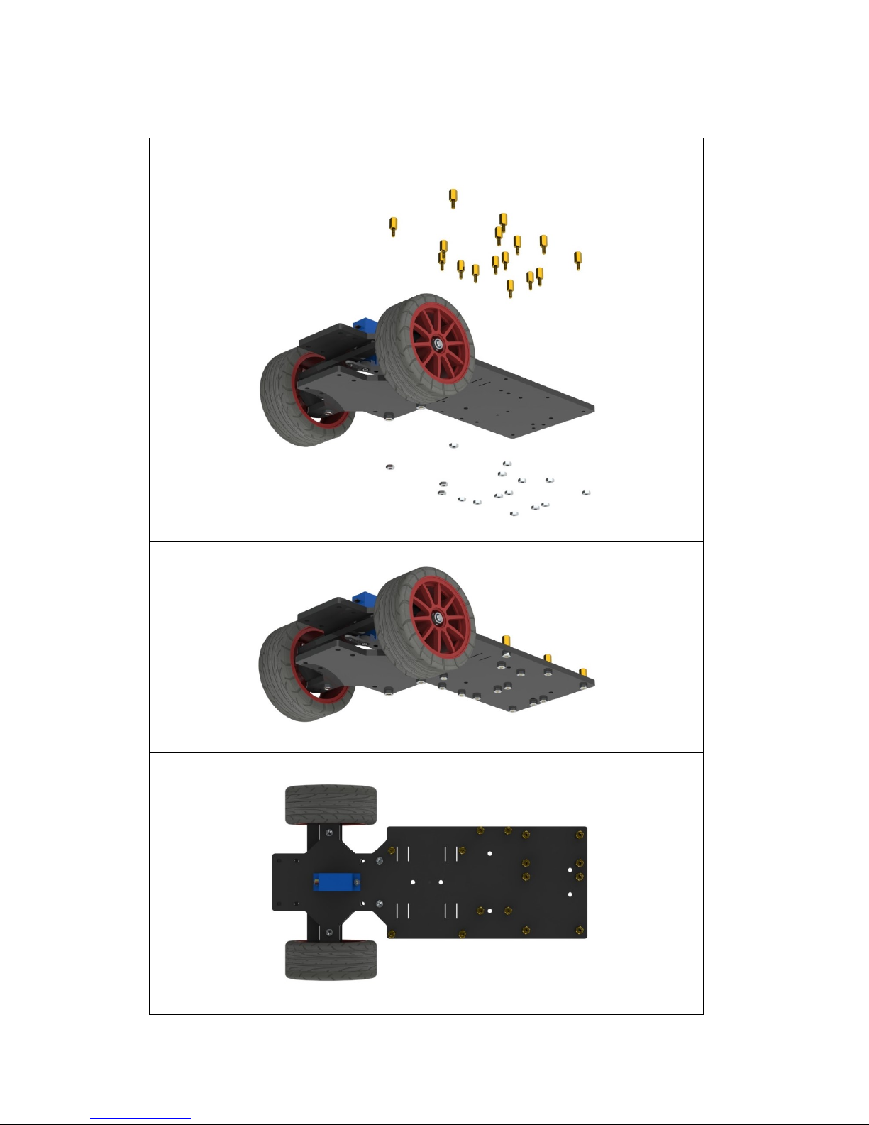
Upper Plate + Copper Standoffs
a) Assemble 16 M2.5*8 copper standoffs and 16 M2.5 nuts into the acrylic
plate as shown below.
b) When completed, the assembly should look like the figure below.
c) The view from the back of the plate:
Page 23
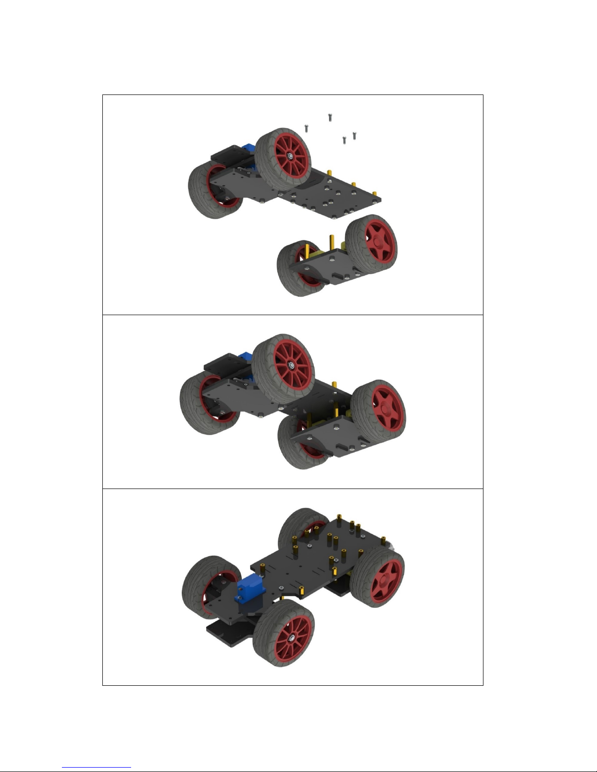
21
Back Chassis + Upper Plate
a) Connect the two assembled parts with 4 M3*8 screws.
b) When completed, the assembly should look like the figure below.
c) The view from the back of the plate:
Page 24
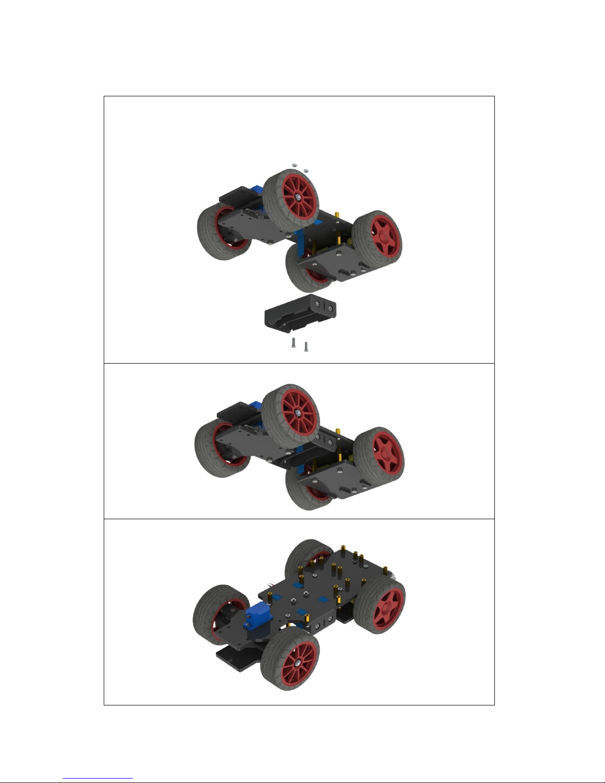
22
Battery Holder
a) Assemble the battery holder to the plate below with 2 M3*10 countersunk
screws and 2 M3 nuts.
You can thread a ribbon through the plate below, so it will be easy to remove
the battery, which is up to you.
b) When completed, the assembly should look like the figure below.
c) The view from the top is as follows. Now the car assembly is completed.
Page 25
23
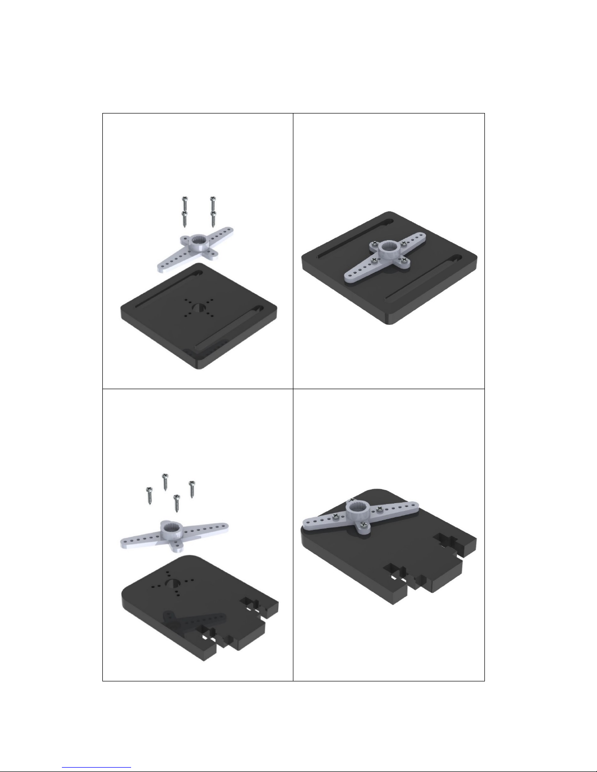
2. Mount Assembly
Plate + Servo Rocker Arm
a) Connect the rocker arm of the
servo to the acrylic plate below
with 4 M1.2*5 screws.
The rocker arm is packaged
together with the servo.
b) When completed, the assembly
should be like the figure below.
a) Connect the rocker arm of the
servo to the acrylic plate below
with four M1.2*5 screws.
The rocker arm is packaged
together with the servo.
b) When completed, the assembly
should be like the figure below.
Page 26
24
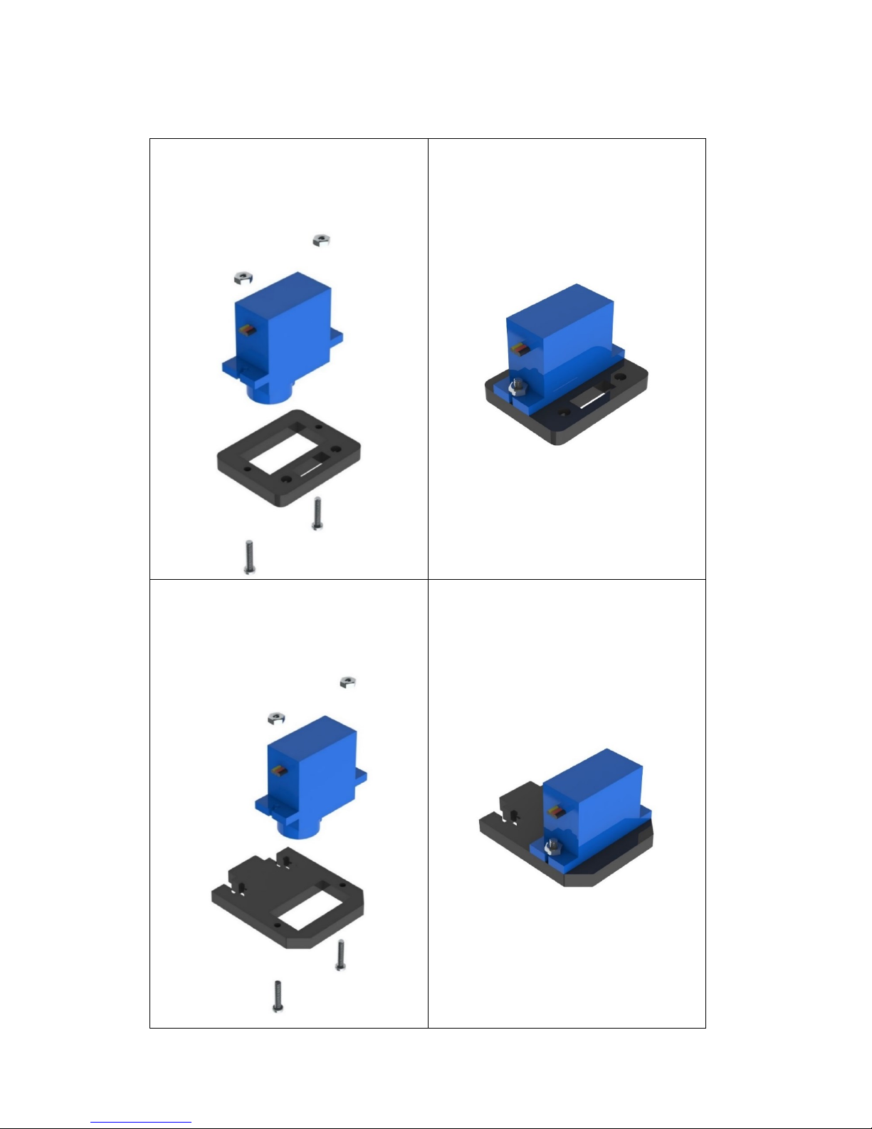
Plate + Servo
a) Connect the servo to the acrylic
plate below with two M2*10
screws and M2 nuts, and we name
it "pan servo".
b) When completed, the assembly
should look like the figure below.
a) Connect the servo to the acrylic
plate below with two M2*10
screws and M2 nuts and we name
it "tilt servo".
b) When completed, the assembly
should look like the figure below.
Page 27
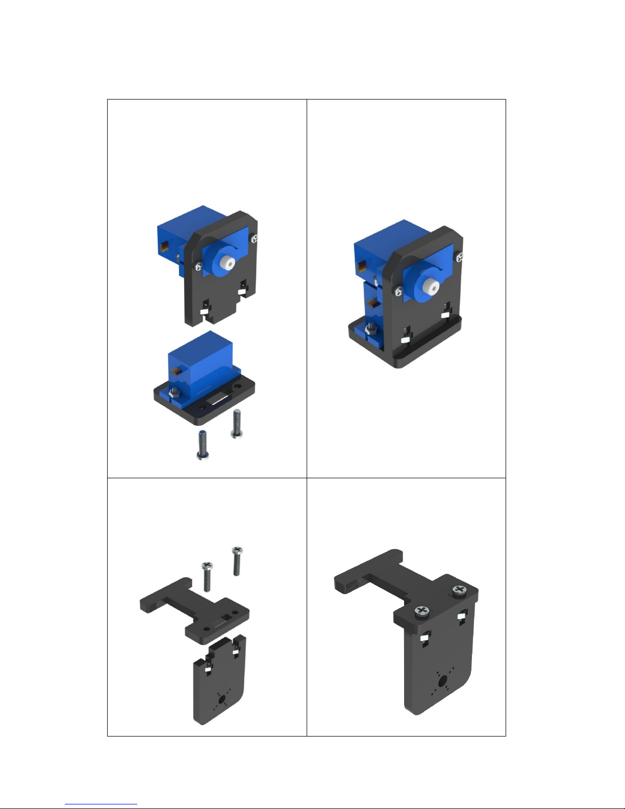
25
Plate + Plate
a) Connect the two plate parts
together with two M3*12 screws
and M3 nuts. The two plates
should be perpendicular to each
other.
b) When completed, the assembly
should look like the figure below.
a) Connect the two parts at a right
angle with two M3*12 screws and
M3 nuts.
b) When completed, the assembly
should look like the figure below.
Page 28
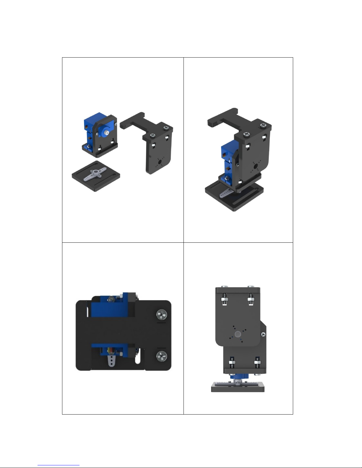
26
Servo + Rocker Arm
a) Connect the following parts without
any screws.
b) When completed, the assembly
should look like the figure below.
Top view:
Front view:
Page 29
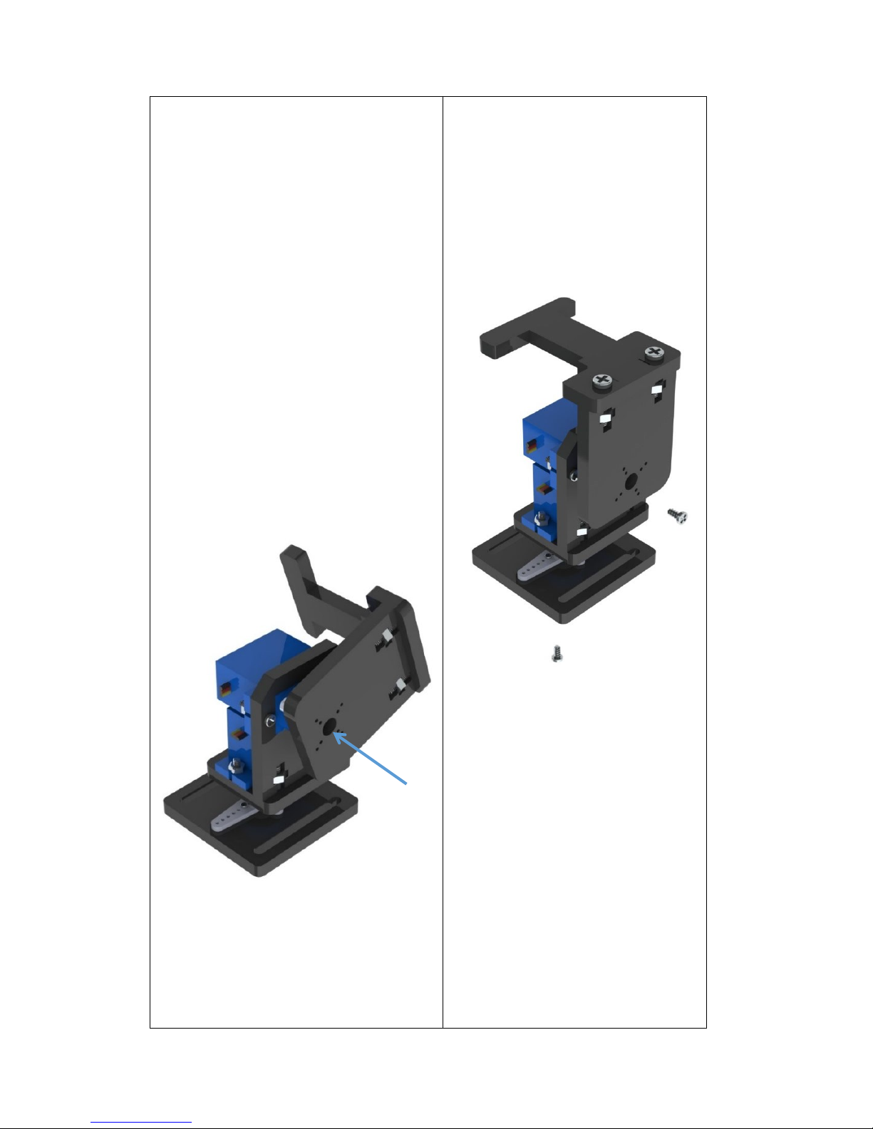
27
The assembly should be like this:
Before screwing, verify the rotation
angle first. Take the orientation of
the tilt servo shaft as the right side,
as shown below. The pan servo
should rotate within the range from
0 to 180 degrees, left to right; the
tilt servo should rotate also 0 to 180
degrees, front to back.
Pay attention to the orientation
during the assembly. If you find any
error in the course, do not try to turn
the axis of the servo; instead, you
should disassemble it and then
assemble the parts again.
c) Then fasten them with an M2*4
screw.
The M2*4 screw is contained in
the package of the servo and is
the shortest of the screws.
Right
Page 30
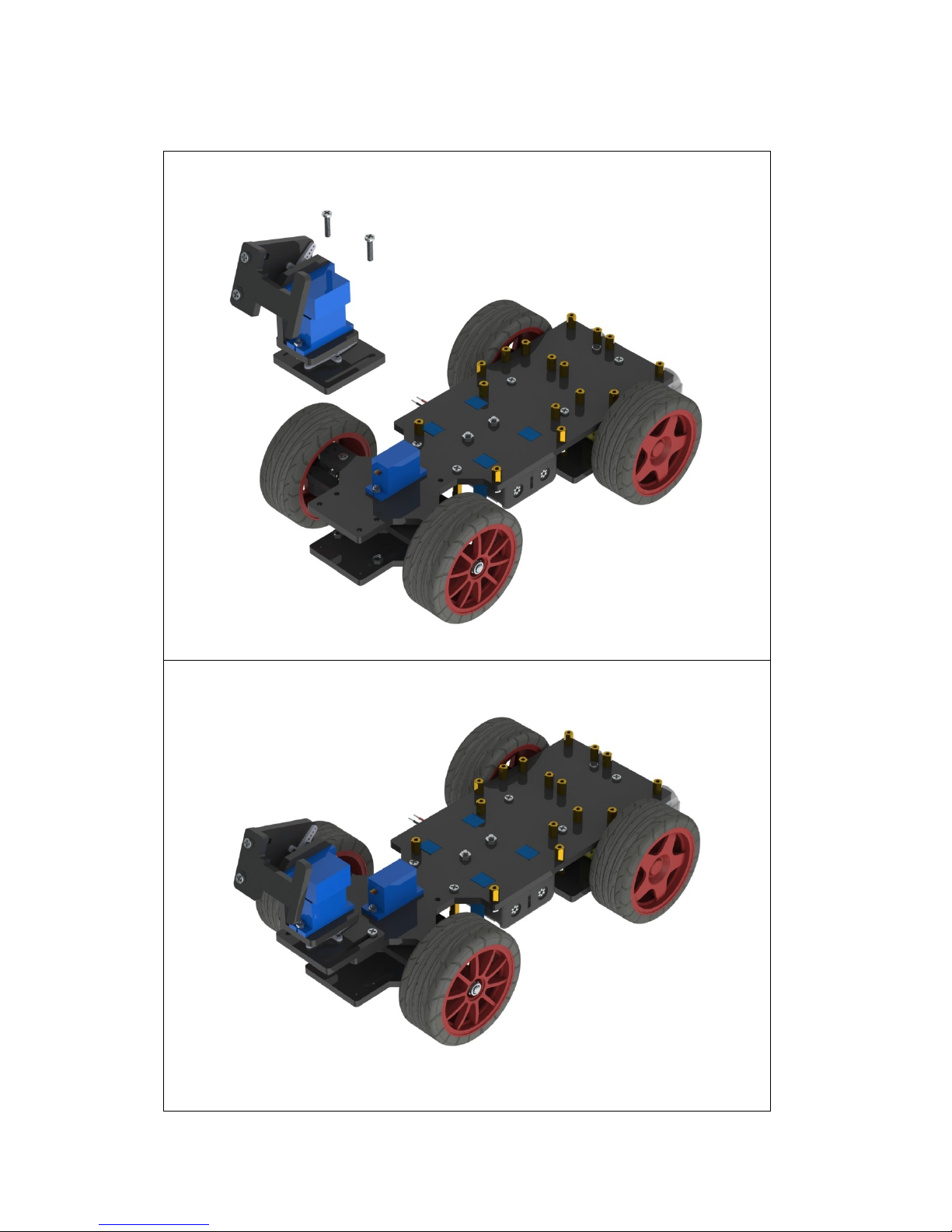
28
3. Mount + Car
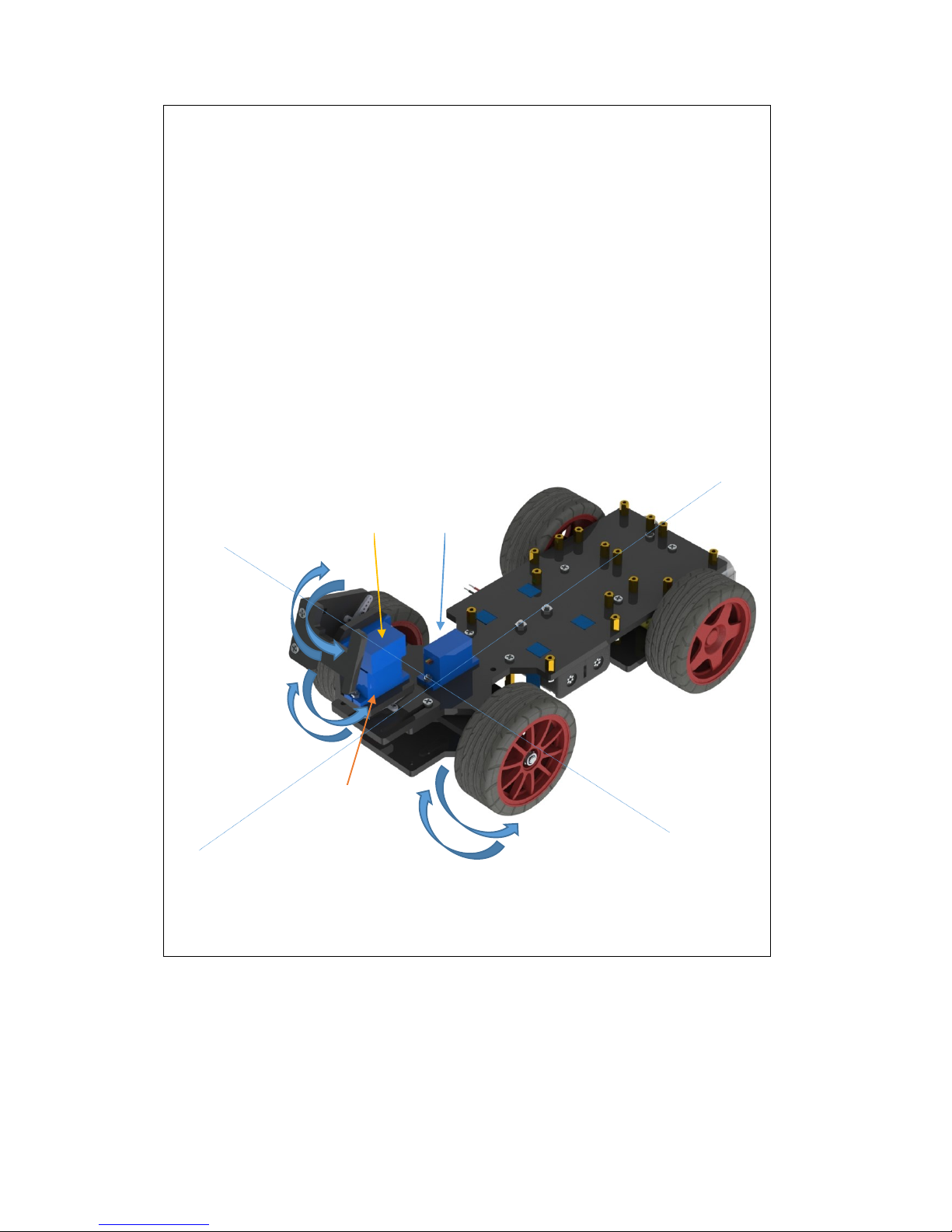
a) Assemble the mount part and the car with two M3*12 screws and M3 nuts.
b) When completed, the assembly should look like the figure below.
Page 31
29
c) Before the next assembly, you need to check the steerability of the servos.
1) First turn the front wheels right and left; pay attention to the utmost
degree of turning: the wheels should be able to turn to a same degree
towards both sides.
2) Turn the pan servo of the mount part right and left to see if its turning
works normally – turning precisely left to right or vice versa.
3) Turn the tilt servo front to back and see if it is able to turn from precisely
front to back or vice versa.
If any of the three servos fails to meet the condition, disassemble it and adjust
based on Servo Adjustment on Page 14. Please DO follow the instructions to
adjust the servos; or else they may get burnt in subsequent operations!
1)
2)
3)
Right
Left
Front
Back
Page 32
30
ii. Electrical Module Assembly
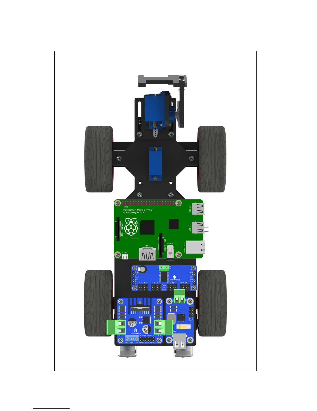
Assemble the electrical components to the car with M2.5*6 screws.
See the figure below.
Page 33
31
iii. Circuit Connecting
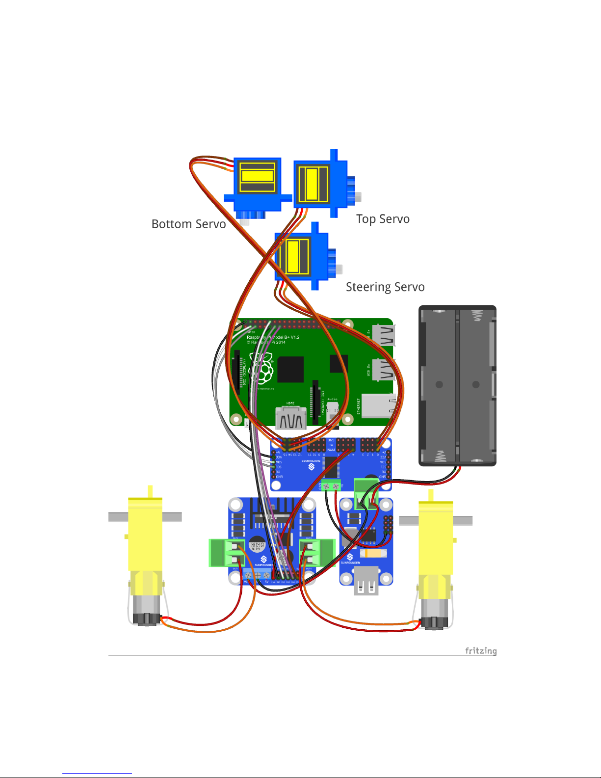
Preview:
This is how it looks when all wiring is done. Looks complicated but don't worry! The
detailed procedures will be given below, step by step.
Page 34
32
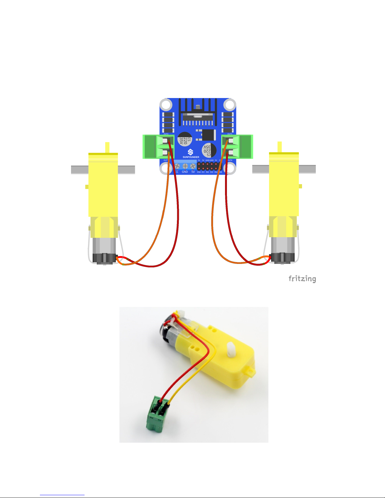
Step 1: Connect the two DC motors with the motor driver.
You may remove the L-shaped PCB connector and plug it back after wiring.
Note: It doesn't matter how to wire the motors. After all the assembly is done, if the
car moves in an opposite direction of what you control, just swap the wiring of the
two motors and it will work normally.
After wiring, it should be like this:
Page 35
33
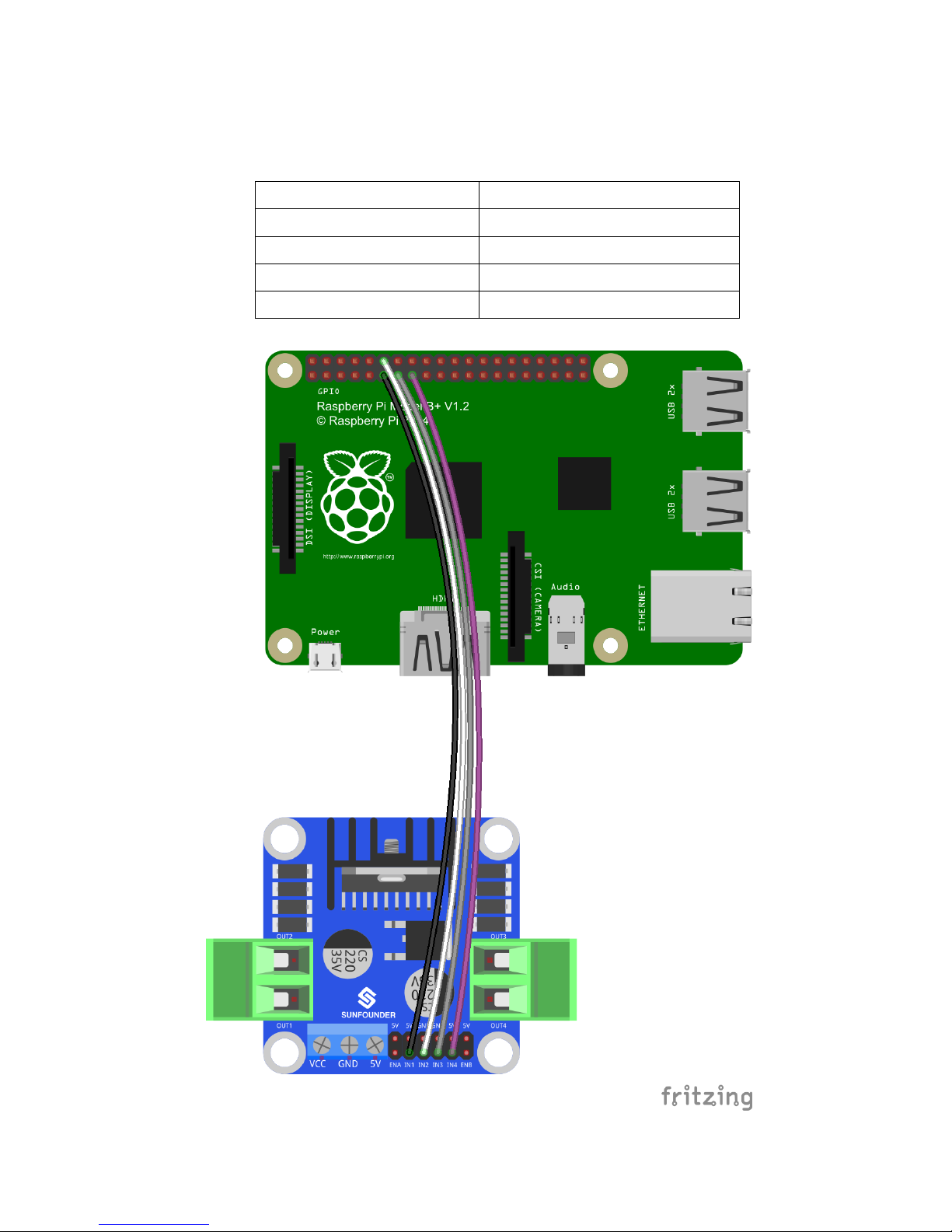
Step 2: Connect the motor driver with the Raspberry Pi GPIO port based on the
following table.
Raspberry Pi GPIO Port
DC Motor Driver
Pin11
IN1
Pin12
IN2
Pin13
IN3
Pin15
IN4
Page 36
34
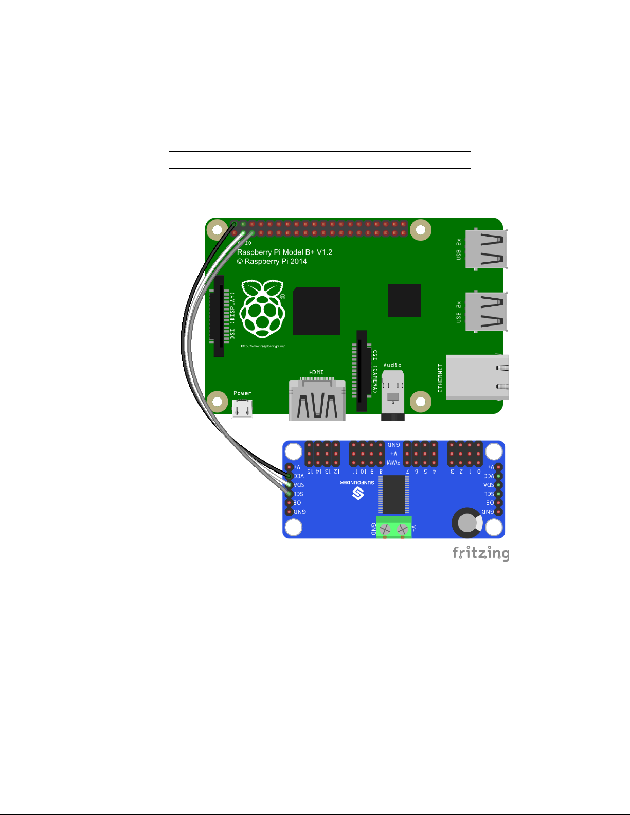
Step 3: Connect the servo controller with the Raspberry Pi GPIO port as follows:
Raspberry Pi GPIO Port
Servo Controller
Pin2(5V)
VCC
Pin3(SDA)
SDA
Pin5(SCL)
SCL
Page 37
35
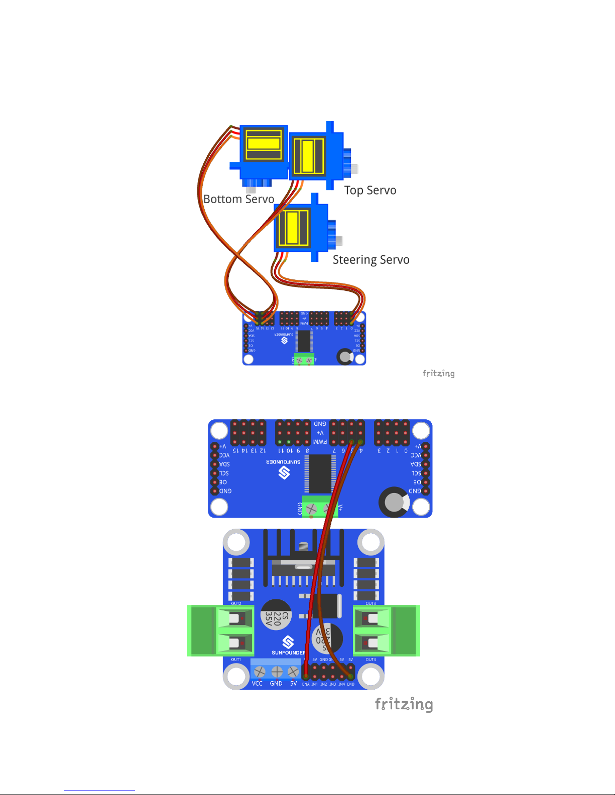
Step 4: Hook up the servo that controls the car's direction to CH0 of the servo
controller, and the two servos that control the view of the camera to CH14 and
CH15 respectively, as shown below:
Step 5: Connect the motor driver with the servo controller.
Page 38
36
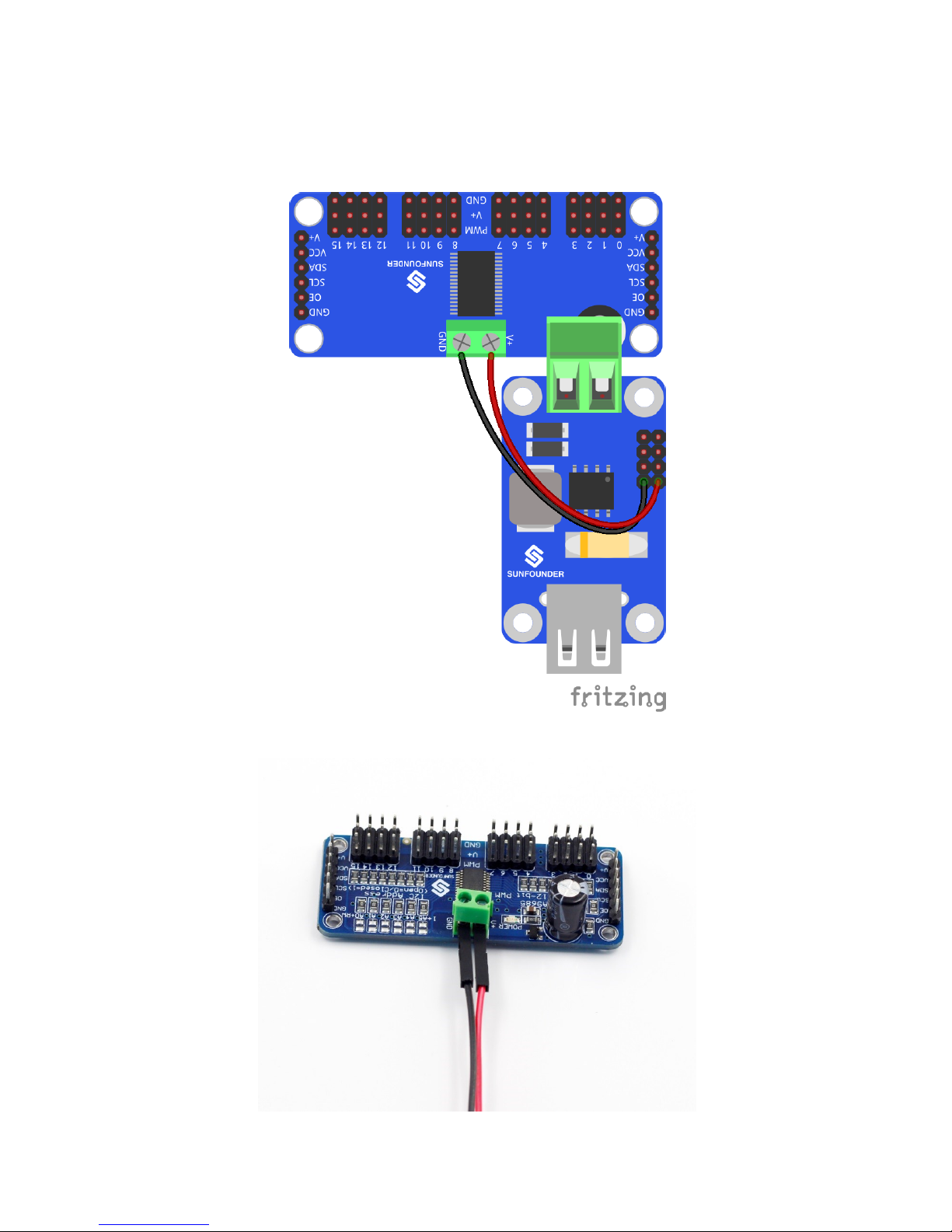
Step 6: Connect the servo controller with the step-down DC-DC converter
module. For the connector, loosen the screws, insert the wire, and then tighten
the screws with a screwdriver.
The connection should be like:
Page 39
37
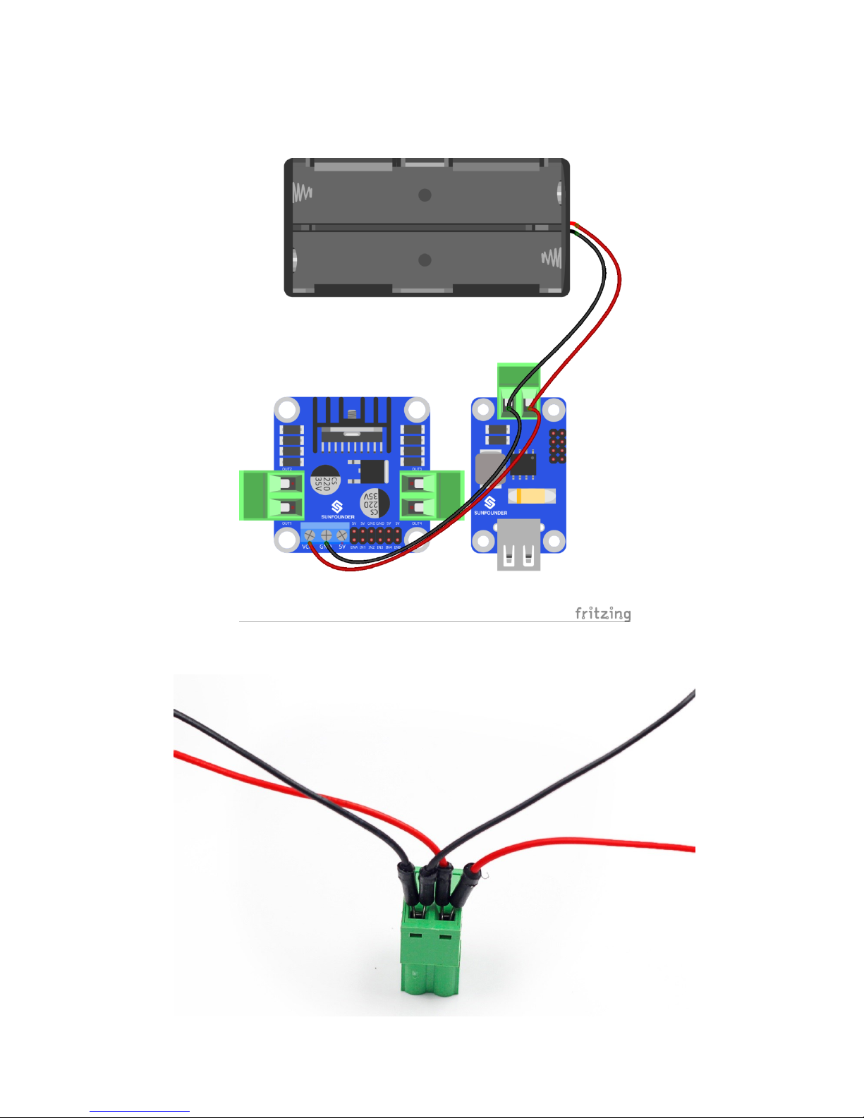
Step 7: Connect the battery holder with the step-down DC-DC converter module
and the DC motor driver.
Insert the four wires into two jacks of the connector, two in each.
Page 40
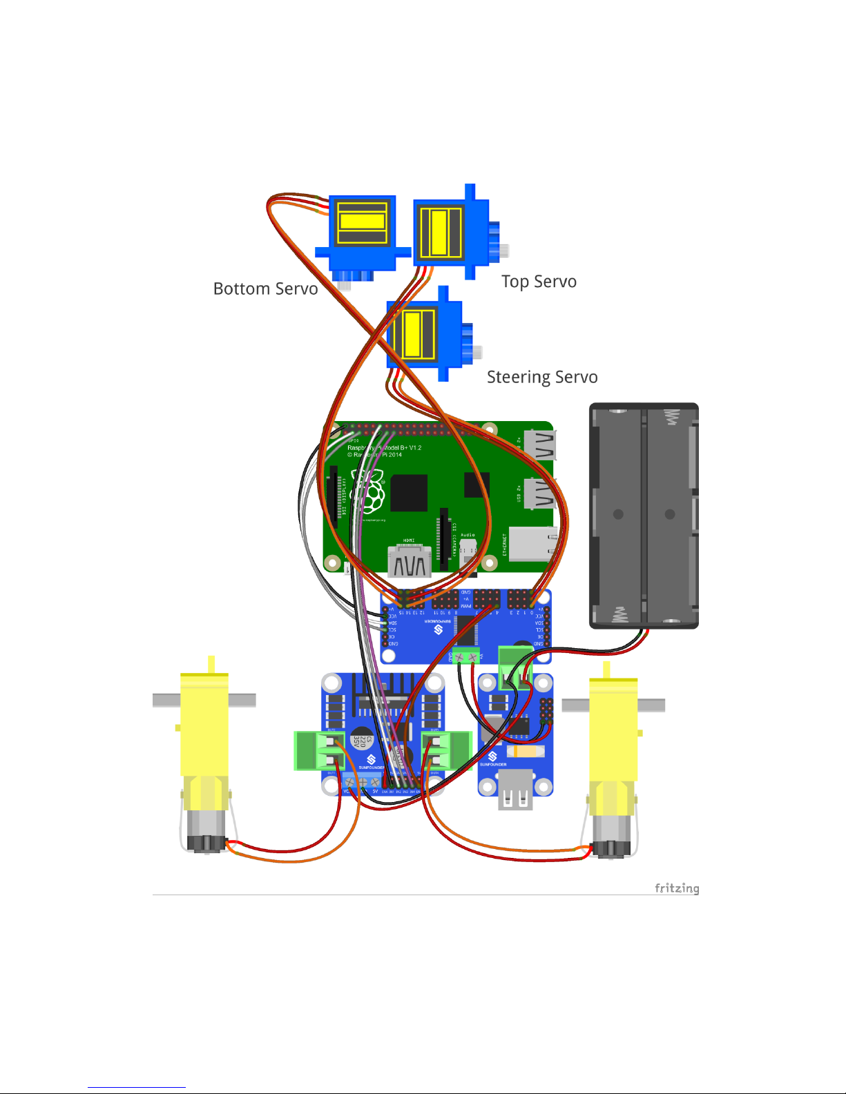
38
The whole picture of wiring should be like this:
Page 41
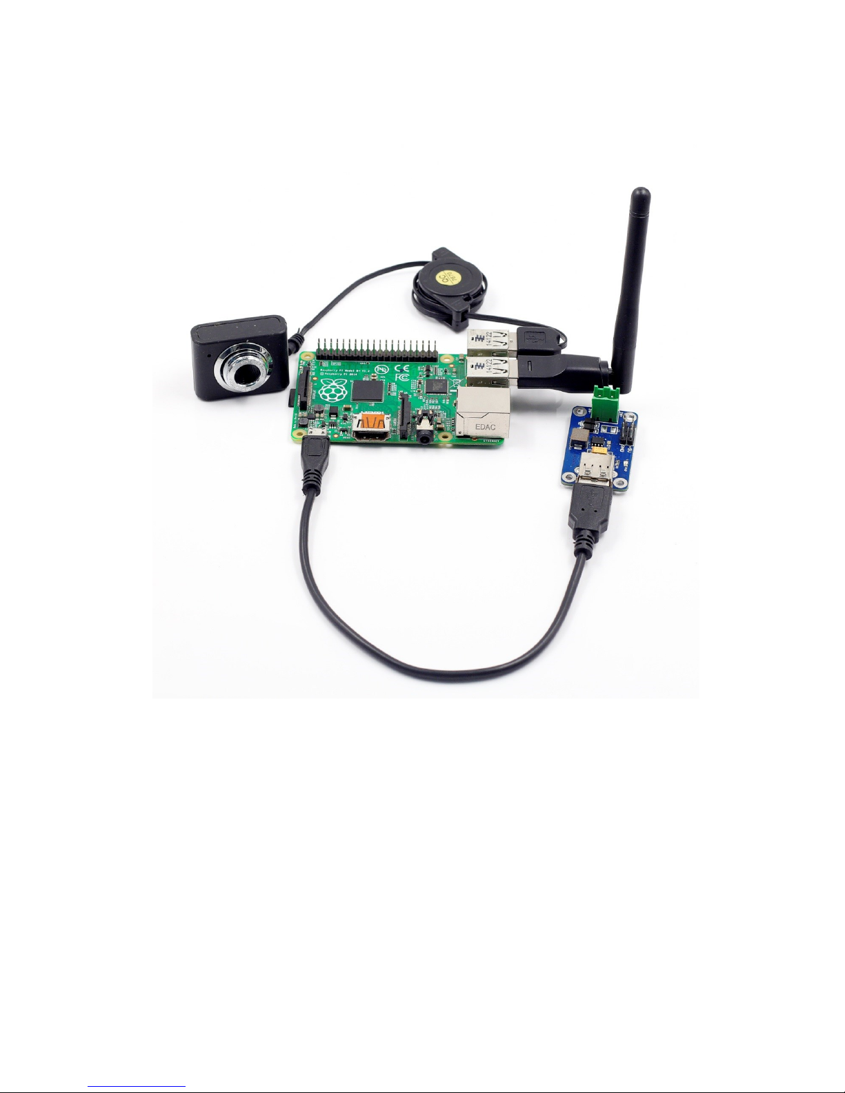
39
Step 8: Connect the Raspberry Pi with the step-down DC-DC converter module,
the USB Wi-Fi adapter and the USB camera.
Page 42
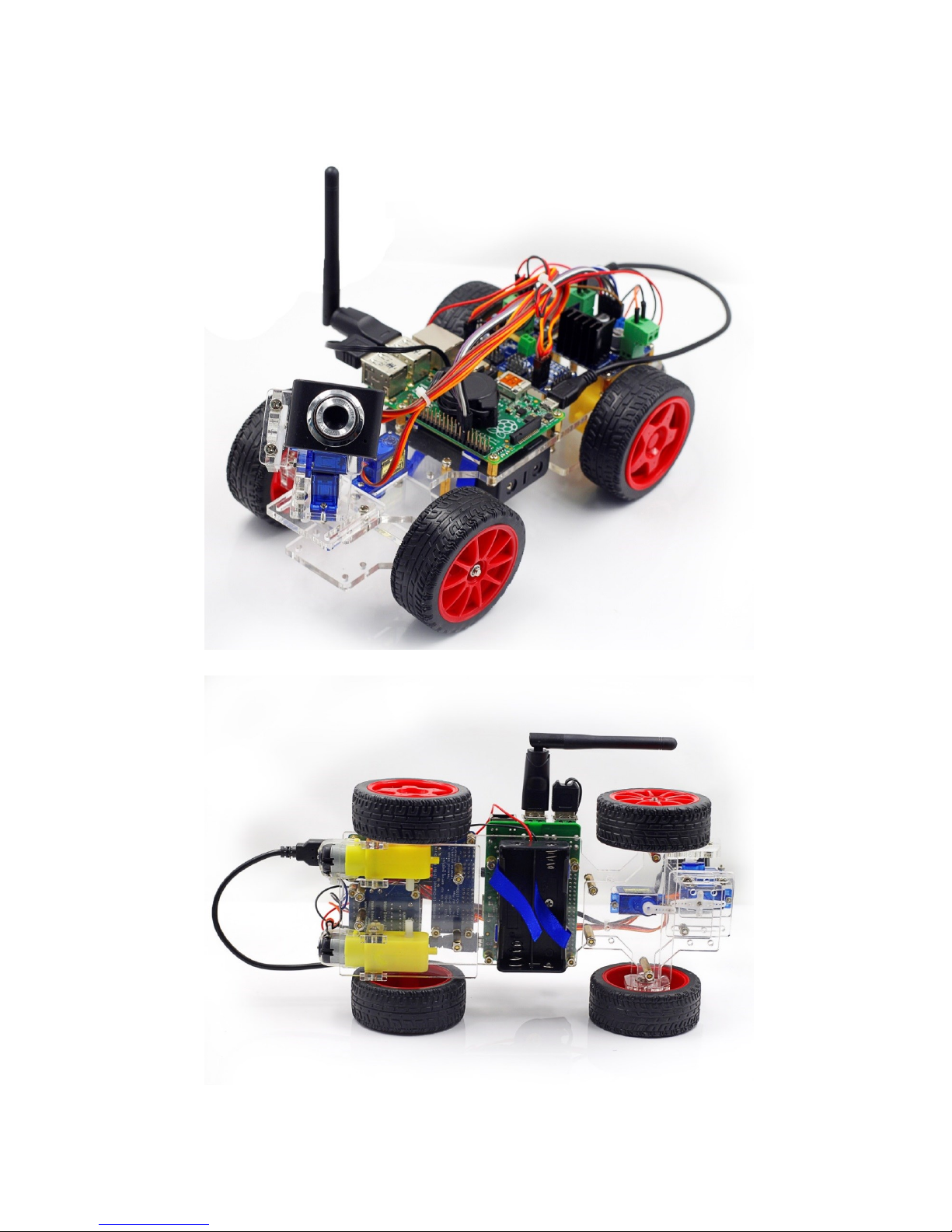
40
Now the circuit is completed. Congratulations!
The car should be assembled successfully as shown below:
Page 43
41
Electrical Components Basics
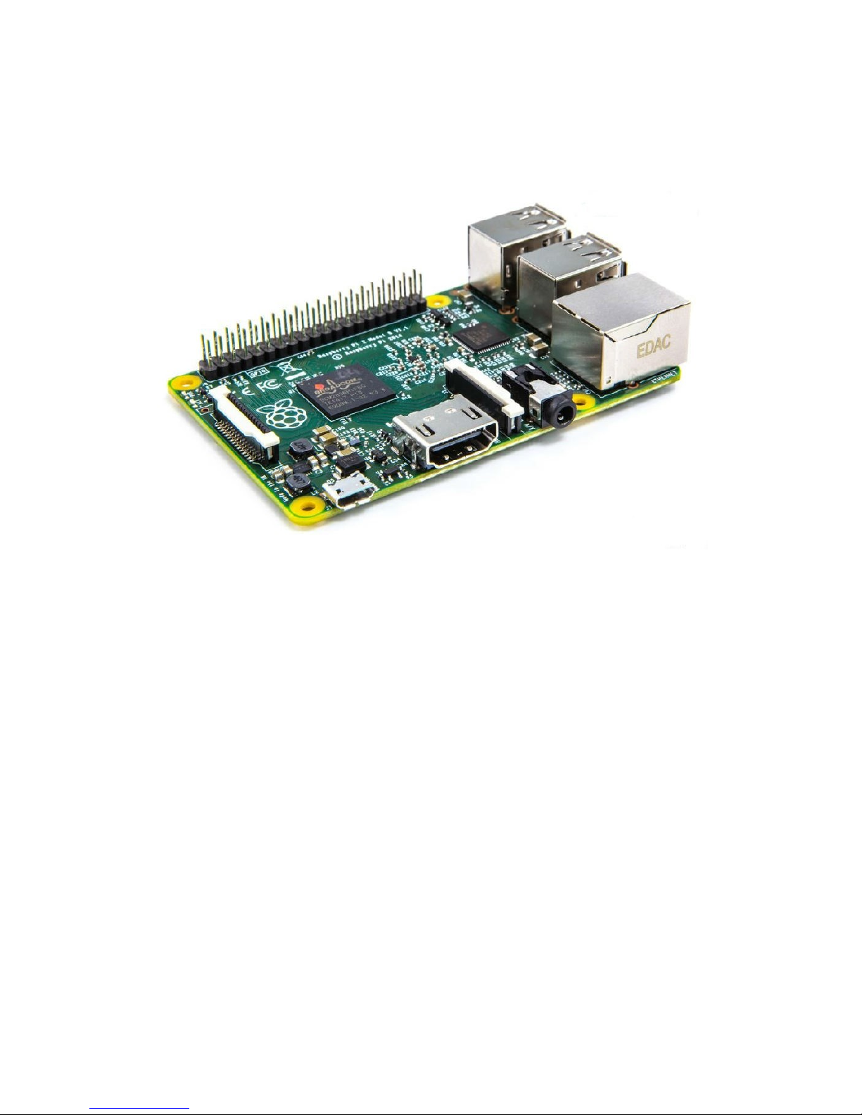
i. Raspberry Pi
The Raspberry Pi is a low cost, credit-card sized computer that plugs into a
computer monitor or TV, and uses a standard keyboard and mouse. It is a
capable little device that enables people of all ages to explore computing,
and to learn how to program in languages like Scratch and Python. It's
capable of doing everything you'd expect a desktop computer to do, from
browsing the internet and playing high-definition video, to making
spreadsheets, doing word-processing, and playing games.
What's more, the Raspberry Pi has the ability to interact with the outside
world, and has been used in a wide array of digital maker projects, from
music machines and parent detectors to weather stations and tweeting
birdhouses with infra-red cameras.
In this kit, we use Raspberry Pi as the core controller of driving equipment
like DC motor and servo. With the device and a camera collaborated, video
data can be acquired in a real-time manner and delivered by Wi-Fi network.
Page 44
42
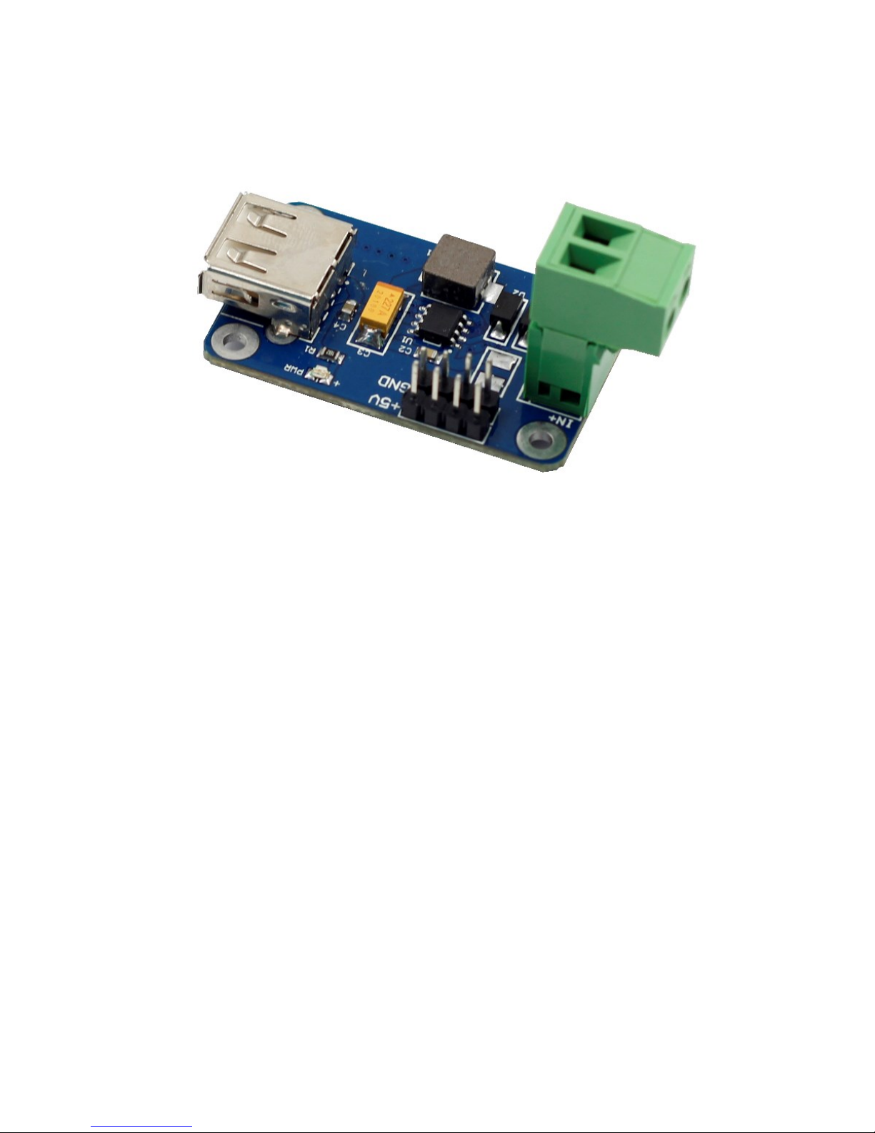
ii. Step-down DC-DC Converter Module
Built based on the chip XL1509, the module converts the battery output of 7.4V to
5V, so as to supply power to Raspberry Pi and the servo. As a DC to DC converter IC,
the chip has an input voltage ranging from 4.5V to 40V and generates an output
voltage of 5V with a current of as high as 2A. Please note: only when the input
voltage is up to 6.5V, a 5V output can be supported.
Page 45
43
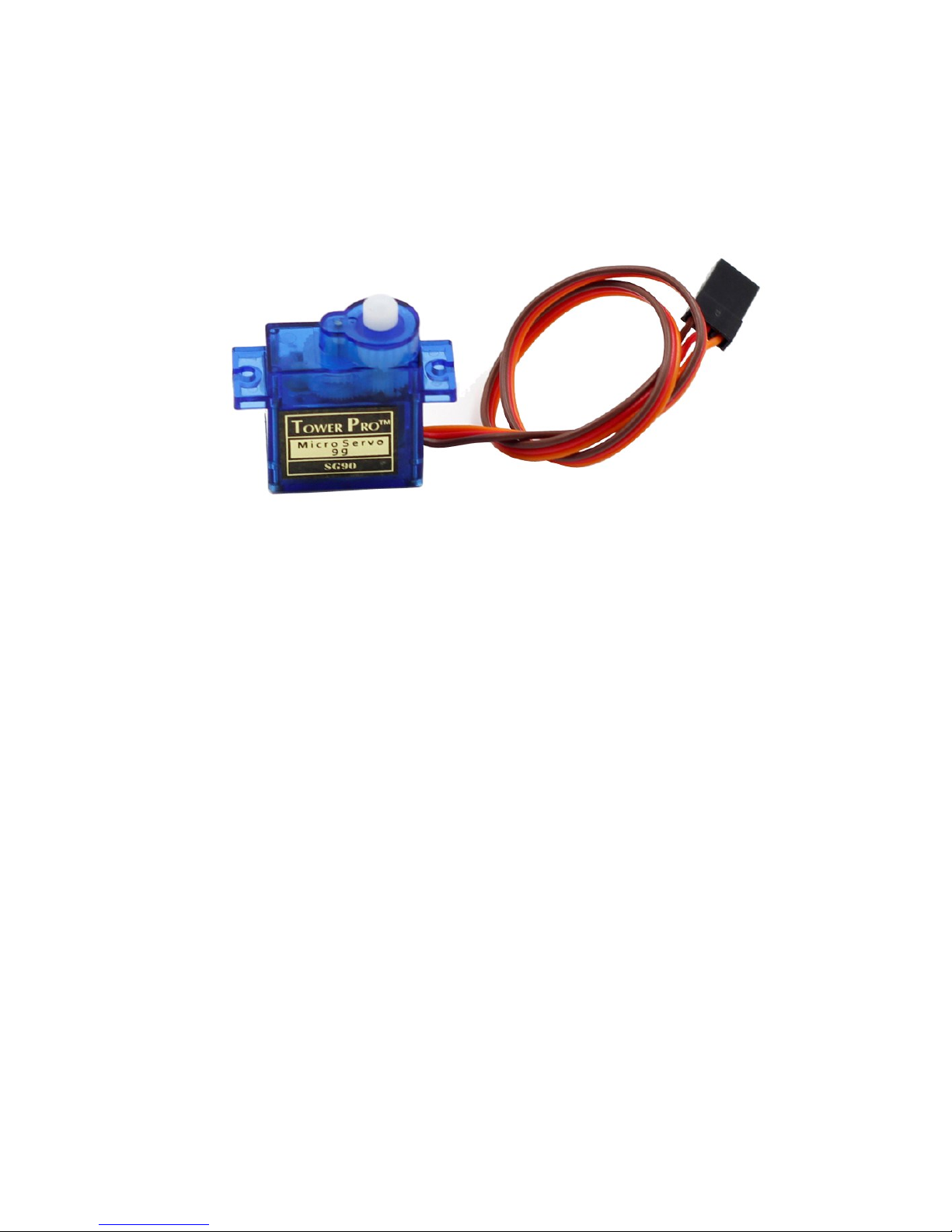
iii. Servo
In this smart car, one servo controls the direction of the car, and the other two, the
movement of the camera between X axis and Y axis, thus defining the coverage of
the camera. A servo is an automatic control system composed of DC motor,
reduction gear set, sensor, and control circuit. It defines the rotation angle of the
output shaft via delivering specific PWM signals. Generally, a servo supports a
maximum rotation angle of the shaft (like 180 degrees). It differs from a common
DC motor in the rotation mode: a DC motor rotates by circle when a servo rotates
in a certain degree and does not rotate in a round circle. Also, the former is used for
power supply by its whole-circle rotation, while the latter is applied to controlling
the rotation angle of an object (like joints of a robot).
Page 46
44
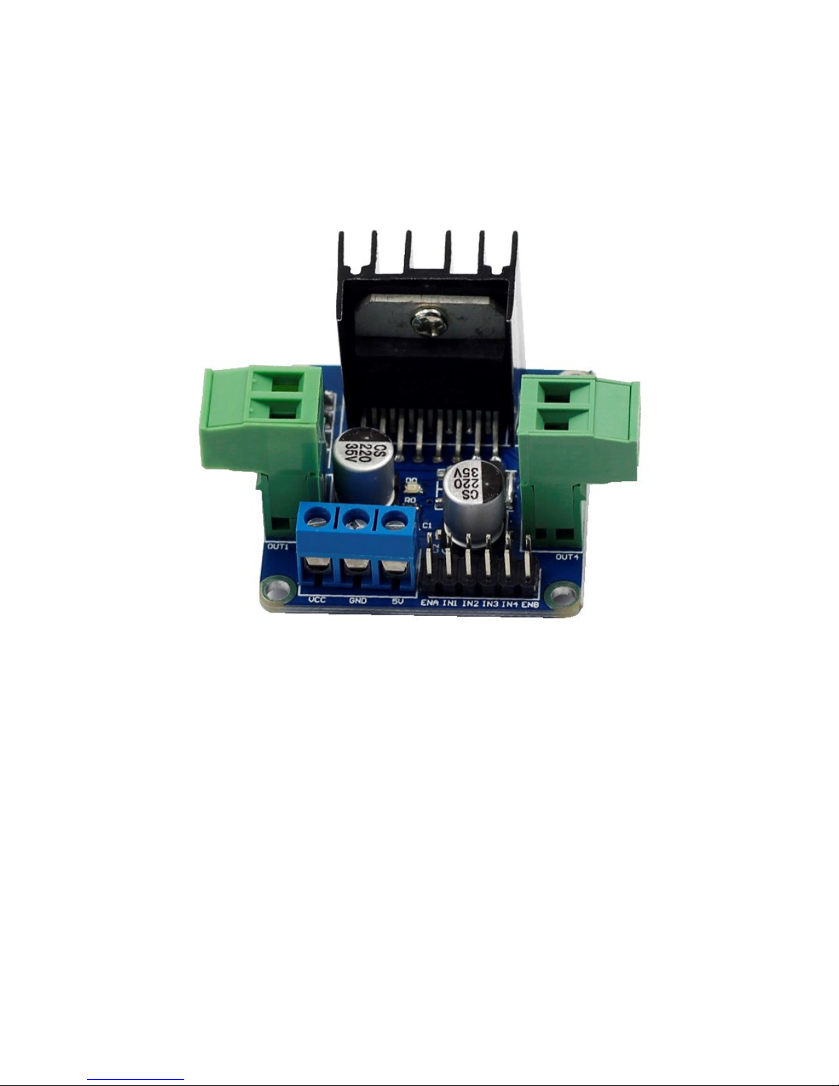
iv. DC Motor Driver
As the name suggests, the module is used to drive DC motors. The driver is built
based on L298N. As a high-voltage and large-current chip for motor driving,
encapsulated with 15 pins, the chip has a maximum operating voltage of 46V and
an instant peak current of as high as 3A, with an operating current of 2A and rated
power of 25W. Thus, it is completely capable of driving two low-power DC motors.
Page 47
45
v. Servo Controller
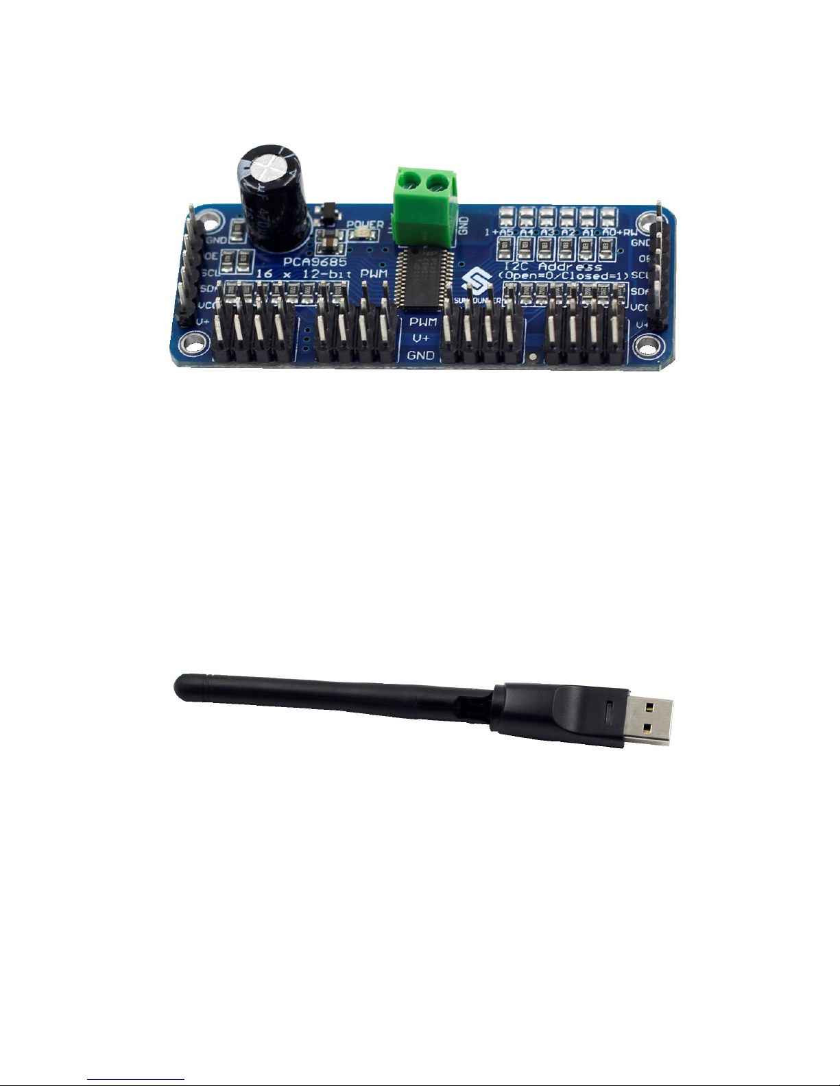
The Servo Controller is built based on PCA9685. PCA9685 is a 16-channel LED
controller with I2C bus interface. The resolution ratio of each channel is 12 bits
(212=4096 levels). The controller works in a frequency between 40Hz and 1000Hz
and its duty cycle can be adjusted in a range of 0 to 100%. It provides PWM signals
for the servo and controls the rotation angle of the servo. Meanwhile, the module
controls the duty cycle of the square waves output from channel 14 and 15 to
regulate the rotational speed of the DC motor, so as to control the speed of the car.
vi. USB Wi-Fi Adaptor
The adapter helps Raspberry Pi connect to a Wi-Fi hot spot.
Page 48

46
Software Related
i. Download and Install Raspbian on a TF Card
If you've already installed the Raspbian system, please skip this step.
Search out the installation guide for Raspbian on the Raspberry Pi website at
https://www.raspberrypi.org/downloads/. Then download the Raspbian to your TF
card and install it.
After the installation, you may need some basic settings for the Raspberry Pi. Check
out the guide for the setting on our website www.sunfouner.com.
ii. Get Source Code
a) Download the source code directly from Github to your Raspberry Pi.
cd ~
git clone https://github.com/sunfounder/Sunfounder_Smart_Video_Car_
Kit_for_RaspberryPi.git
Or,
If your Raspberry Pi is not connected to the Internet, download the file
Sunfounder_Smart_Video_Car_Kit_for_RaspberryPi.tar.gz on our website.
- For Linux
Unplug the TF card and connect it with the computer with a card reader.
Then copy the file
Sunfounder_Smart_Video_Car_Kit_for_RaspberryPi.tar.gz to the
directory /home/pi.
- For Windows
Since files in EXT2/3/4 format of Linux cannot be read or written under
Windows, and the car needs to be controlled in Linux, we strongly suggest
you install a virtual machine of Linux for the convenience of development
on the Raspberry Pi.
Then, run the code to extract:
tar xvfz Sunfounder_Smart_Video_Car_Kit_for_RaspberryPi.tar.gz
a) Download the source code directly from Github to your Linux.
Open a terminal in your Linux. Download git:
For Ubuntu/Debian:
sudo apt-get install git
Page 49
47
For Redhat/Fedora:
sudo yum install git
Clone the repository from github:
git clone
https://github.com/sunfounder/Sunfounder_Smart_Video_Car_Kit_for_R
aspberryPi.git
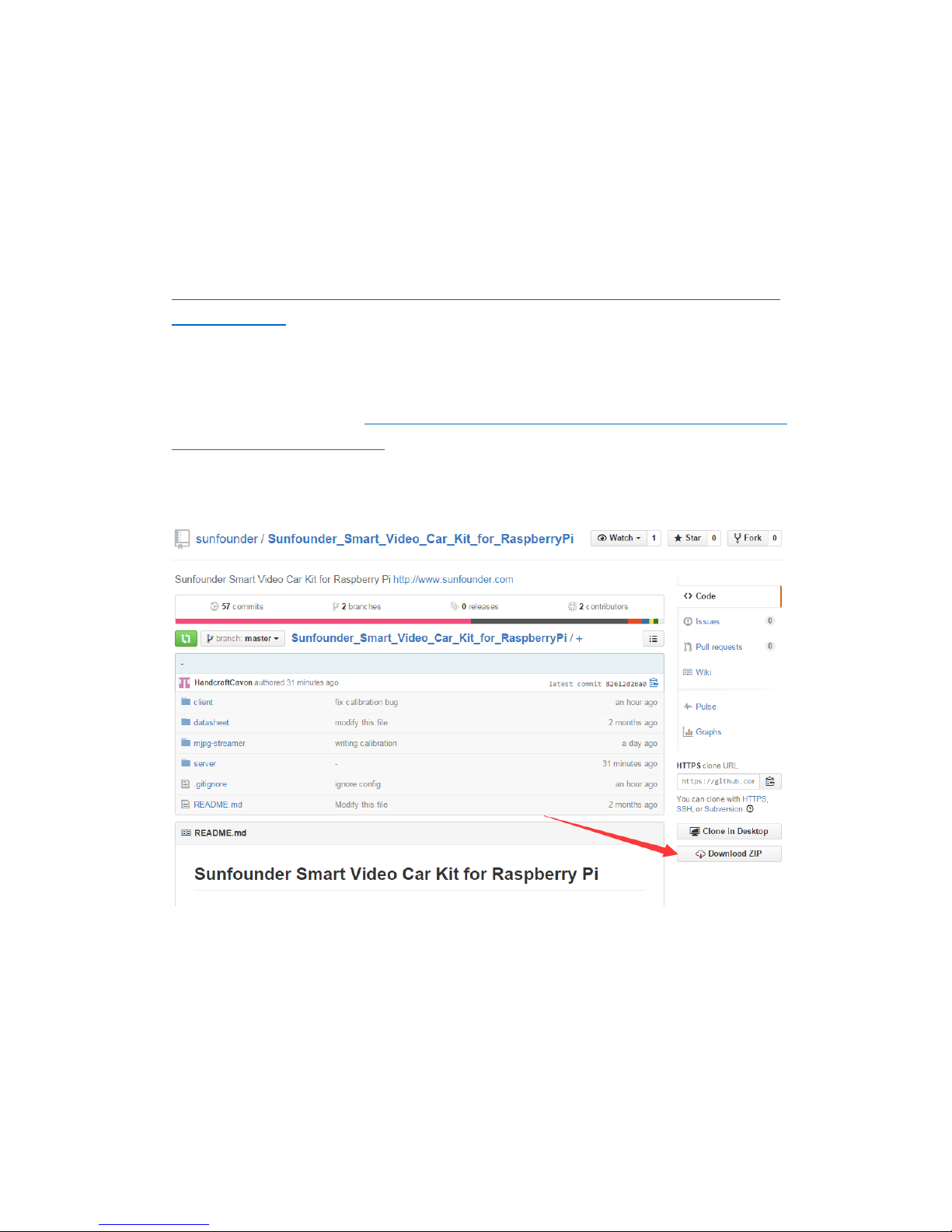
If your Linux does not support installing git by yum or apt-get, you may go t
o the link to download: https://github.com/sunfounder/Sunfounder_Smart_Vid
eo_Car_Kit_for_RaspberryPi, or search for Sunfounder in Github and find Sunf
ounder_Smart_Video_Car_Kit_for_RaspberryPi Repository.
Click Download ZIP on the right side of the page, as below.
After download, right click the file and click Extract here,
Or unzip it by command:
unzip Sunfounder_Smart_Video_Car_Kit_for_RaspberryPi-master.zip
Page 50

48
iii. Basic Software Environment
Operation on PC
Prepare the PC for remote.
Install python-tk for a remote interface
sudo install apt-get install python-tk
Operation on Raspberry Pi
Install python-dev, python-smbus
Type in the code below to install python-dev and python-smbus:
sudo apt-get install python-dev
sudo apt-get install python-smbus
Setup I2C port
Comment out the i2c-bcm2708 line from the raspi-blacklist.conf file:
sudo nano /etc/modprobe.d/raspi-blacklist.conf
Add code below.
#blacklist i2c-bcm2708
Open /etc/modules
sudo nano /etc/modules
And add this line to the end of the file:
i2c-dev
From the prompt, run:
sudo modprobe i2c_bcm2708
sudo modprobe i2c-dev
Check that the i2c modules are loaded and active:
lsmod | grep i2c
Then the following code will appear (the number may be different)
i2c_dev 6276 0
i2c_bcm2708 4121 0
Page 51
49
MJPG-streamer
Introduction
The acquisition and transmission of video data by the SunFounder Smart Video Car
is fulfilled based on MJPG-streamer.
MJPG-streamer is a command line application that copies JPG-frame from a single
input plugin to multiple output plugins. It can be used to stream JPEG files over an
IP-based network from the webcam to a viewer like Firefox, Cambozola and
Videolanclient or even to a Windows mobile device running the TCPMP-Player.
It was written for embedded devices with very limited resources in terms of RAM
and CPU. Its origin, the "uvc_streamer" was written, because Linux-UVC
compatible cameras directly produce JPEG-data, allowing fast and performant
M-JPEG streams even from an embedded device running OpenWRT. The input
module "input_uvc.so" captures such JPG frames from a connected webcam.
Installation
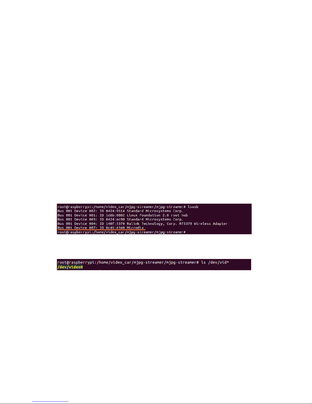
Plug the USB camera into Raspberry Pi, and run the command lsusb. The Microdia
represents the USB camera; since it is printed on the screen, it indicates the system
has recognized the camera.
Check whether the driver for the camera works normally:
ls /dev/vid*
If device node video0 is printed, the driver is in the normal state.
Then, install the following software needed:
sudo apt-get install subversion
sudo apt-get install libv4l-dev
sudo apt-get install libjpeg8-dev
sudo apt-get install imagemagick
Compile the source code of MJPG-streamer:
cd /home/Sunfounder_Smart_Video_Car_Kit_for_RaspberryPi /mjpg-stre
amer/mjpg-streamer
make USE_LIBV4L2=true clean all
Page 52
50
Install:
make DESTDIR=/usr install
Testing
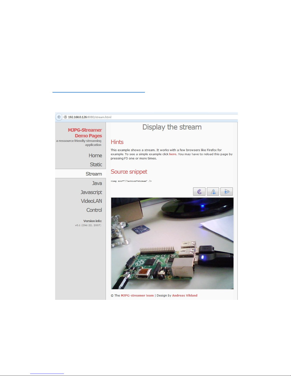
Type in sudo ./start.sh and press Enter.
Type in the following address (replace 192.168.0.xxx with your Raspberry Pi IP
address) at the address bar of your browser (Firefox is recommended):
http://192.168.0.xxx:8080/stream.html
Press Enter and you will see the view captured by the camera displayed on the
screen in a real-time manner.
Page 53
51
iv. Calibration
Preparation
For Server
Make sure that the circuit is connected properly. Power the smart car, open a
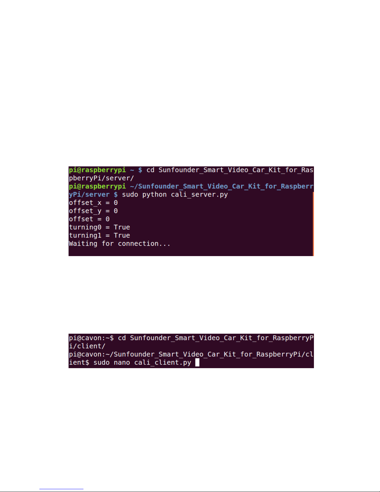
terminal in Linux. Connect with your Raspberry Pi via ssh. Go to the directory
Sunfounder_Smart_Video_Car_Kit_for_RaspberryPi/server, run the server
cali_server.py:
cd ~/Sunfounder_Smart_Video_Car_Kit_for_RaspberryPi /server
sudo python cali_server.py
Then the contents of config are printed and the last line: Waiting for connection…
At this time, the car might move a bit (this is the original position set)
For Client
Open another terminal. Find the sketch downloaded and edit client/cali_client.py:
cd client/
sudo nano cali_client.py
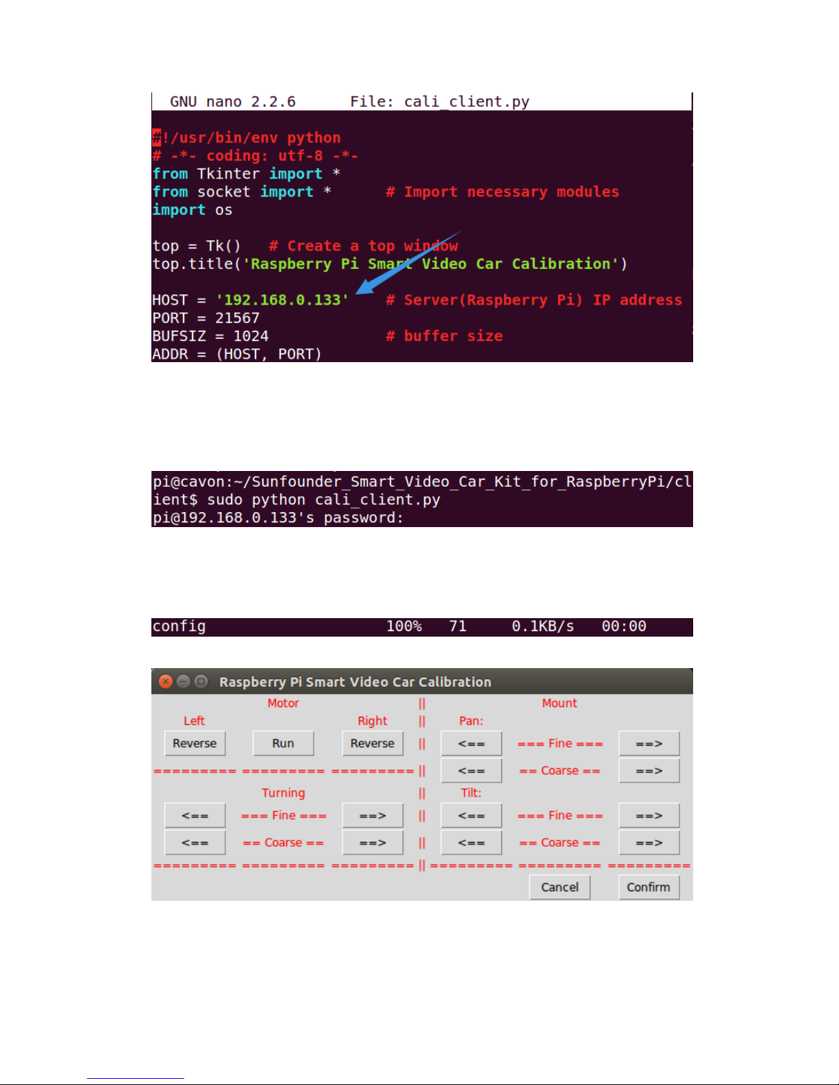
Find the variable of HOST:
Page 54
52
Enter your own address of the Raspberry Pi there. Press Ctrl+O to save and Ctrl+X
exit.
Run cali_client.py:
sudo python cali_client.py
You need to enter the password of the Raspberry Pi here since you want to obtain
the configuration file on it.
Then a line appears as follows, indicating the config file is obtained successfully.
And a window Raspberry Pi Smart Video Car Calibration pops up:
In the terminal remotely connected with the Raspberry Pi, the IP address of the PC
will be printed.
Page 55
53
Then you can start calibrating. Before that, take out your package box and place it
vertically with the side face to the table. Put the car onside the box and keep it
balanced. The purpose is to keep the wheels of the car off the table.
By default, the front wheels should be directly pointed towards the front; the
camera on the tilt servo should be face up no matter what directions the pan servo
is pointed at. If not, you may adjust the directions in Raspberry Pi Smart Video
Car Calibration.
Start Calibration
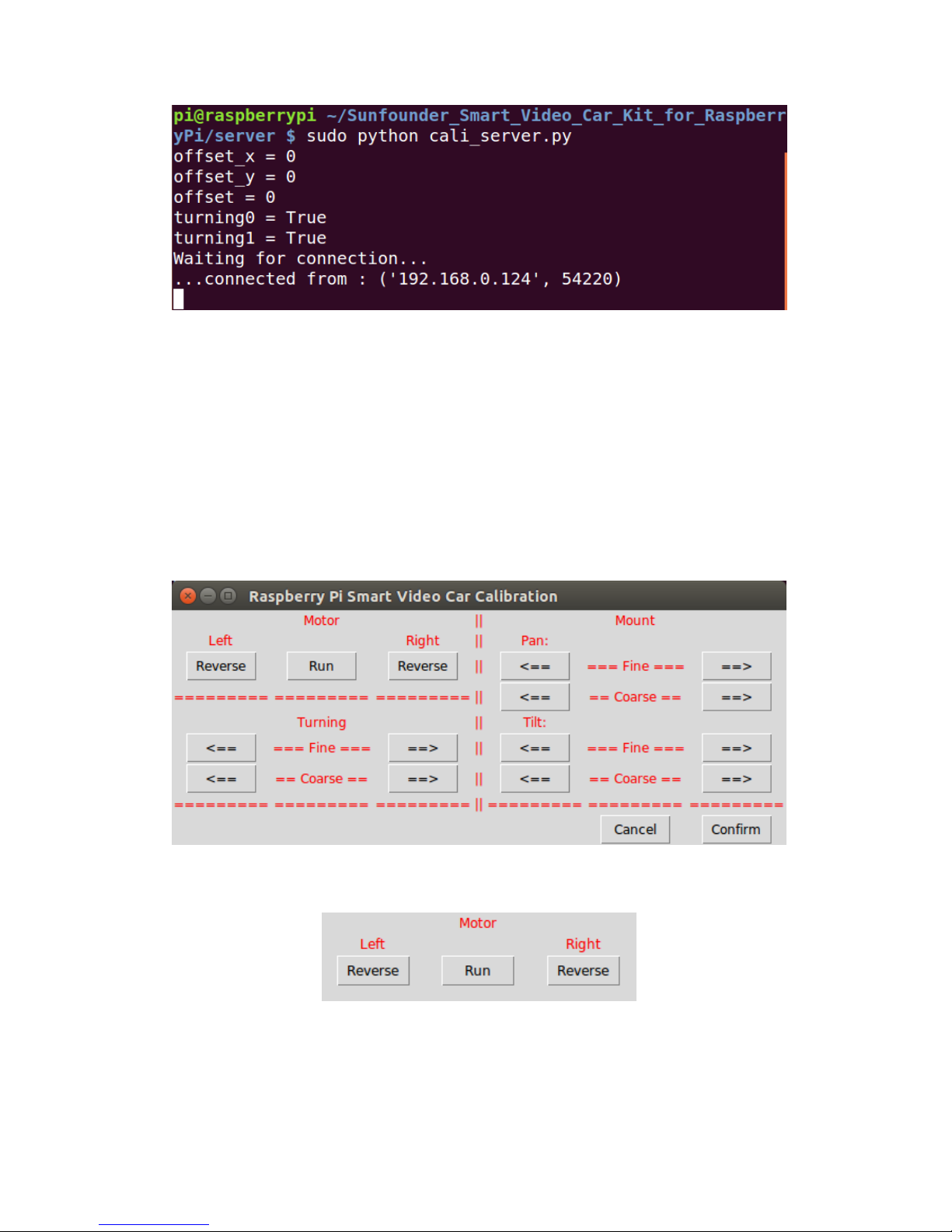
On the calibration UI there are three sections: Motor, Turning, and Mount.
Motor Adjustment
Click Run. The car will walk forward. Check whether both the back wheels move
forward together. If either fails to do so, your wiring may be wrong. But don't worry!
You don't need to rewire; just click the corresponding Reverse in Motor section of
the Calibration window shown above. After clicking, observe whether the wheel
Page 56
54
you just adjusted is turning forward. If the reversing works normally, click Run
again to stop the wheels from spinning.
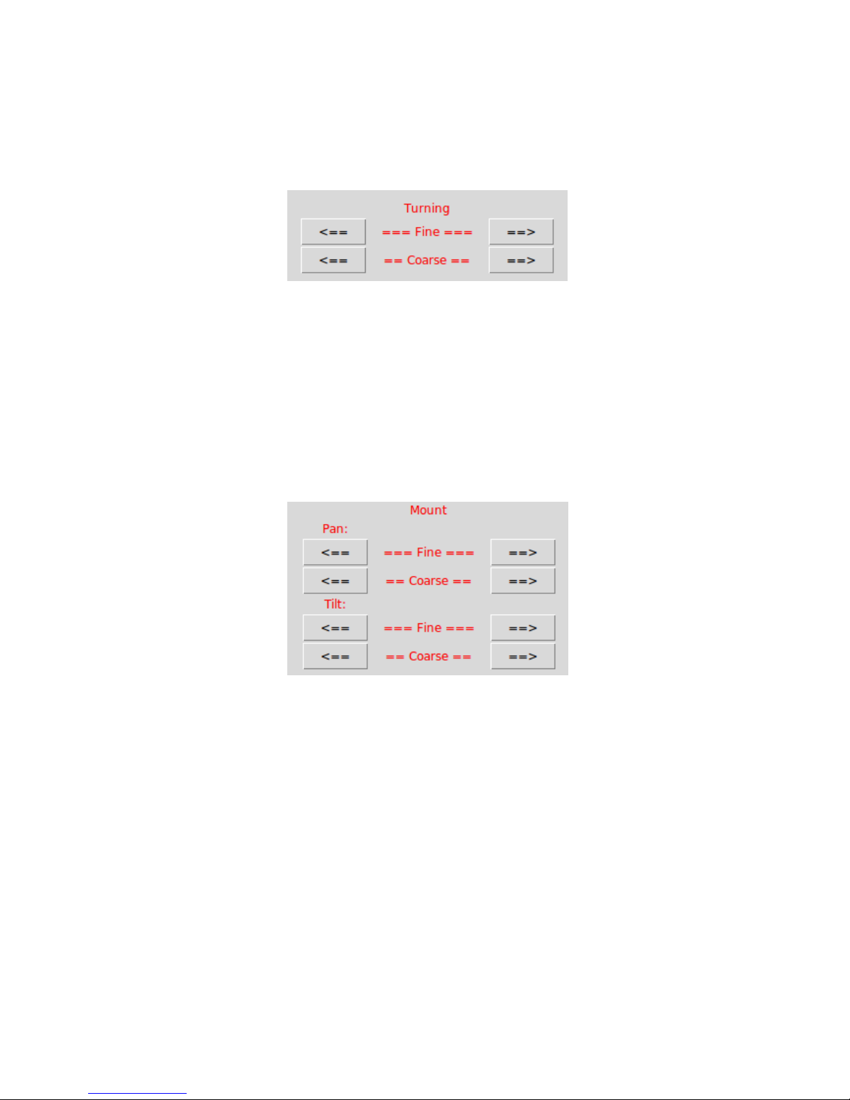
Turing Adjustment
Currently the front wheels should be pointed at the exact front direction. But if it is
not, you need to make some adjustments. In the Turning section in the Calibration
window, click the left (<==) and right (==>) arrow buttons in the upper line to
make fine adjustments, and those in the lower to coarsely adjust the turning
direction. Keep adjusting until the wheels is oriented to the front exactly. Then you
may place the car on the table and click Run to verify whether it runs in a straight
line. If not, perform the adjustment again till it does.
Mount Adjustment
Now the pan servo on the car should be pointed at the exact front direction and the
camera face up. But if not, you may need to adjust them similarly. In the Mount
section, there are the adjustments for the pan servo and tilt one. Also you have two
kinds of adjustments, fine and coarse. Keep adjusting until they are pointed at the
right direction.
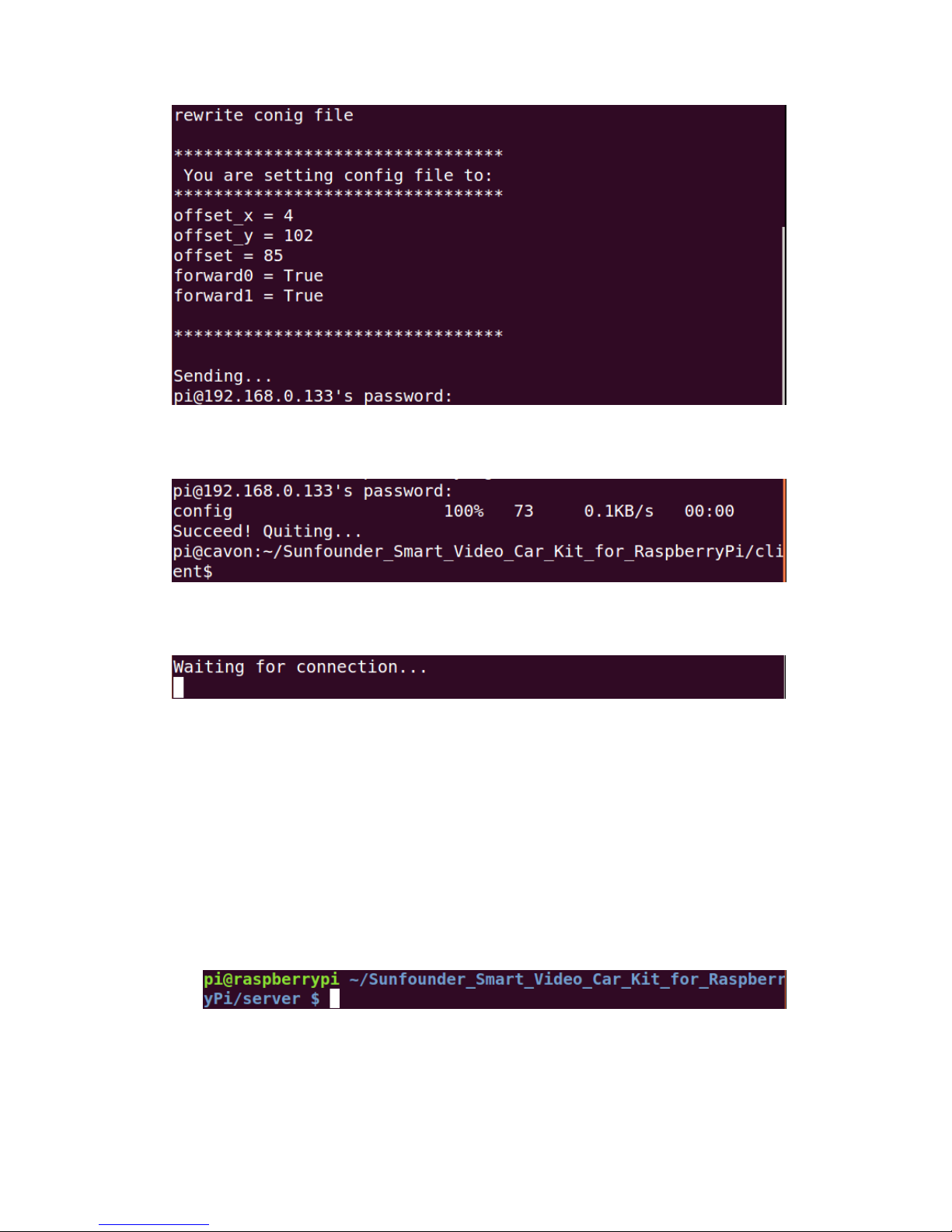
After all the adjustments are done, click Confirm. Then the terminal on PC will print
the contents of the file config after your adjustments. The calibration program will
automatically sends the config to the Raspberry Pi. You may need to enter your
password.
Page 57
55
After the password is entered, the prompt message of config sent successfully will
be printed in the terminal.
And the program will exit.
Then the Raspberry Pi returns to the status: Waiting for connection...
Press Ctrl+C to exit.
Now your car is ready to GO!
Get on the Road!
You need three terminals open to run the car; here we name it Terminal 1,
Terminal 2, Terminal 3. Terminal 1 is to open tcp_server.py on the Raspberry Pi
as a server, Terminal 2 is to run web camera server on it, and Terminal 3 is to
open client_App.py on PC as a client to remote.
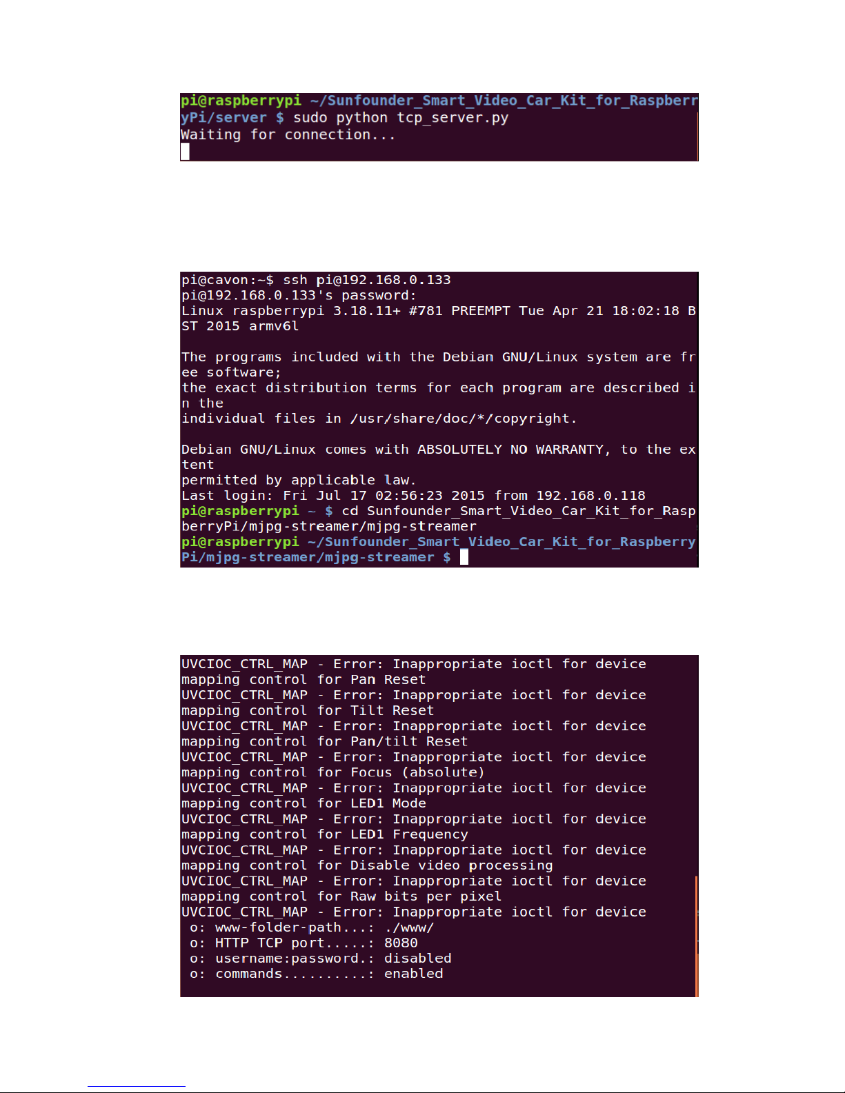
- In Terminal 1
The Raspberry Pi may be still at the server directory
If not, go to the directory with cd and run tcp_server.py:
sudo python tcp_server.py
The server program on the Raspberry Pi will be running and waiting for the
client to connect to the Raspberry Pi.
Page 58
56
- Open another terminal, i.e. Terminal 2, log in the Raspberry Pi remotely, and
switch to the directory under which the program of MJPG-streamer lies:
cd ~/Sunfounder_Smart_Video_Car_Kit_for_RaspberryPi/mjpg-strea
mer/mjpg-streamer
Run the program:
sudo sh start.sh
Then the video data acquisition will start, like this:
Page 59
57
Type in the following address (replace 192.168.0.xxx with the IP address of
your Raspberry Pi) at the address bar of your browser (Firefox is
recommended):
http://192.168.0.xxx:8080/stream.html
Press Enter and you will see the view captured by the camera displayed on the
screen in a real-time manner.
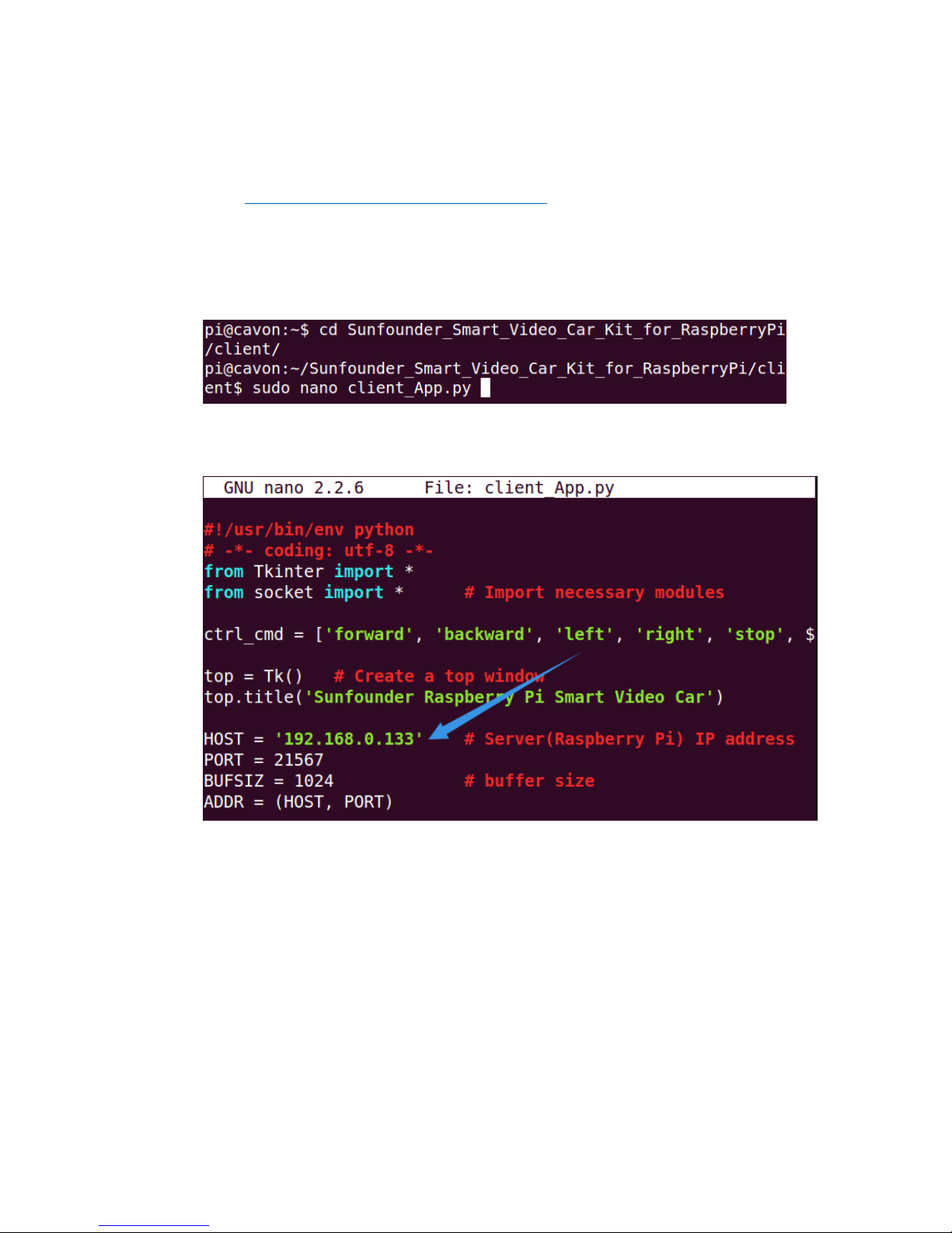
- Open the last terminal, Terminal 3. Go to client with cd and edit the file
client.py:
Similar to the change in calibration, change the IP address in the client program
in your PC:
After the alteration, press Ctrl+O and save and Ctrl+X to exit.
Then run the client program:
sudo python client_app.py
Page 60
58
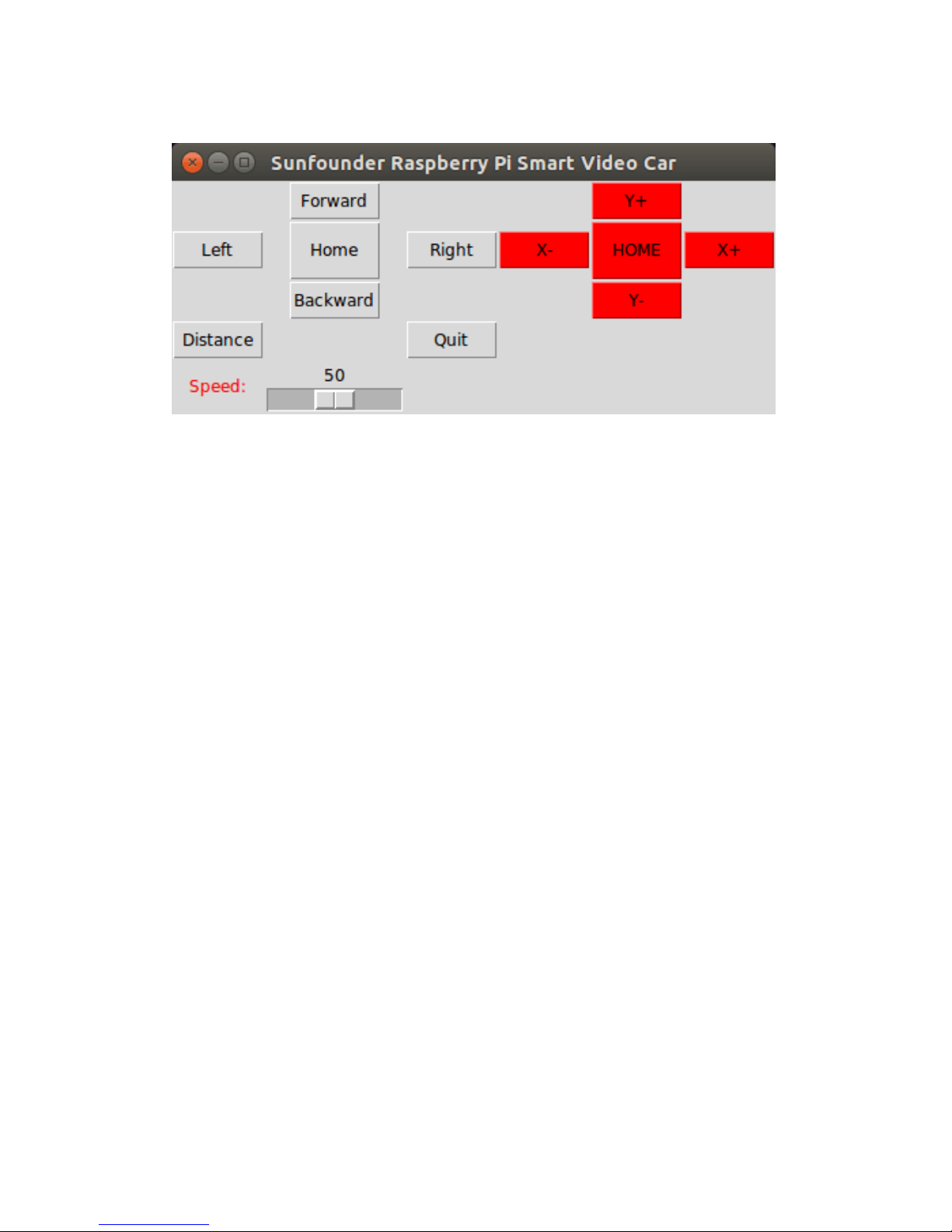
The following picture will appear on your screen:
You can click buttons such as Forward and Backward to control the car moving
remotely. Or click X+, X-, Y+, and Y- to control the coverage of the camera.
Note:
The server program must be run before you run the client program. Some settings must be
completed for the server before the service is done. A communication endpoint needs to be
created for the server to "listen" to requests from the client. Take the server as a receptionist
or an operator of the bus phone in a company. Once the phone and device installation is
completed and the receptionist or operator is in place, the service begins.
Page 61
59
v. Program Analysis and Explanation
Abstract
From the perspective of software, the smart car is of C/S structure. The TCP server
program is run on Raspberry Pi to listen to the command from the client and control
the car accordingly. The client program is run on the PC and connected with the
server through the TCP, which provides the user with a graphical user interface
(GUI) to conveniently control the Raspberry Pi remotely. Both the client and server
programs are written in Python.
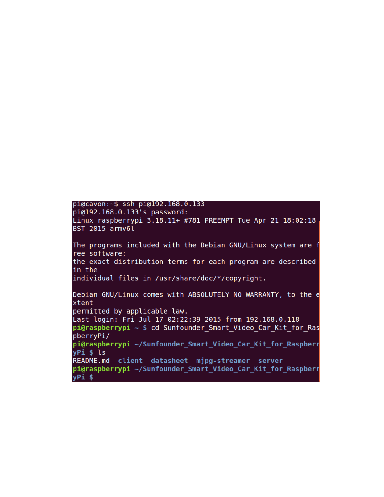
Make sure that the circuit is connected properly. Power the smart car, log in t
he Raspberry Pi remotely, go to the directory Sunfounder_Smart_Video_Car_K
it_for_RaspberryPi and check the files under it.
cd Sunfounder_Smart_Video_Car_Kit_for_RaspberryPi
ls
You can see four files under the directory: client, datasheet, mjpg-streamer and
server, and a file README.md.
Wherein,
README.md is an introduction file,
client, the client run on your PC,
Page 62

60
datasheet contains some PDF files about the chip (you need to view them on PC),
mjpg-streamer, the camera driver to acquire and upload images
server, the server run on the Raspberry Pi
Introduction of Socket
The C/S-structure program of the SunFounder Raspberry Pi-based Smart Car is
written based on the socket module of the Python language. Socket wraps and
applies the TCP/IP and is used to describe IP address and port. Also it is a network
data structure for computer. The socket module should be created before the
communication of network applications. If the socket can be said to be the plug of
a telephone, which is the lowest layer of communication, then the combination of IP
address and ports can be said to be that of area code and phone numbers. Only
having the hardware for a phone call making is not enough. You still need to know
whom and where to call. An Internet address is composed of the essential IP
address and port for network communication.
1. Server
Here we provide a pseudocode which creates a universal TCP server for explanation.
Note that this is just one of the methods for server design. After you have a good
knowledge about it, you can alter the pseudocode as you want:
s = socket( ) # Create a socket for the server.
s.bind( ) # Bind the address to the socket.
s.listen( ) # Listen to the connection.
inf_loop: # Indefinite loop of the server.
c = s.accept( ) # Accept the connection from the client.
comm_loop: # Communication loop.
c.recv( )/c.send( ) # Dialog (receiving or sending data)
c.close( ) # Close the socket of the client.
s.close( ) # Close the socket of the server (optional).
All kinds of socket can be created via the function socket.socket( ) and then bound
with IP address and port by the function bind( ). Since TCP is a connection-oriented
communication system, some settings need to be completed before the TCP server
starts operation. The TCP server must "listen" to connections from the client.
After the settings are done, the server will enter an indefinite loop. A simple, like
single-thread, server will call the function accept( ) to wait for the coming
connection. By default, the function accept( ) is a blocking one, which means it is
suspended before the connection comes. Once a connection is received, the
function accept( ) returns a separate client socket for the subsequent
communication. After the temporary socket is created, communication begins.
Both the server and client use the new socket for data sending and receiving. The
Page 63
61
communication does not end until either end closes the connection or sends a null
character string.
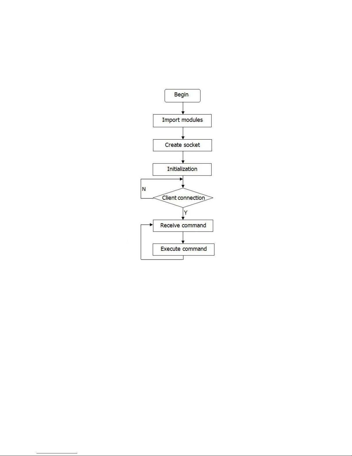
Process Diagram of Server Program
2. Client
It is easier to create a TCP client than to do a server. Take the following
pseudocode:
c = socket( ) # Create a client socket.
c.connect( ) # Try to connect a server.
comm_loop: # Communication loop.
c.send( )/c.recv( ) # Dialog (sending out and receiving data)
c.close( ) # Close the client socket.
As mentioned above, all sockets are created via the function socket.socket( ). Then,
the function connect( ) can be called to connect the server. After the connection is
built, the dialog between the client and the server is enabled. When the dialog ends,
the client can close the socket and the connection.
Page 64
62
Introduction of Tkinter
Developed based on Tkinter, our client program carries graphical interfaces. Tkinter
is a GUI widget set for Python. We can develop application programs with graphical
interfaces fast by Python language based on it. It is quite easy to use Tkinter. All
you have to do is to import the module into Python.
To create and run a GUI program, take the following steps:
a) Import the Tkinter module (by import Tkinter or from Tkinter import *).
b) Create a top window object to contain the whole GUI program.
c) Create the GUI module needed on the object and enable the functions.
d) Connect the GUI modules with the code at the system back-end.
e) Enter the main event loop.
Take a simple GUI program:
Create a file Tk_test.py under the path /home:
touch Tk_test.py
Add executable privilege to the file:
chmod +x Tk_test.py
Open the file:
vim Tk_test.py
Type in the following code:
#!/usr/bin/env python
from Tkinter import *
top = Tk() # Create a top window
top.title('Sunfounder.com')
label = Label(top, text='Hello Geeks !', fg='blue') # Create a label and set its foreground color as blue
label.pack() # layout
top.mainloop() # main loop
Save the code and exit.
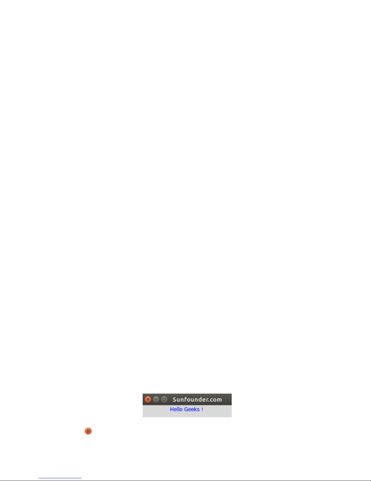
Run
./Tk_test.py
Then the following picture will appear on your screen:
Click to close the program.
Page 65
63
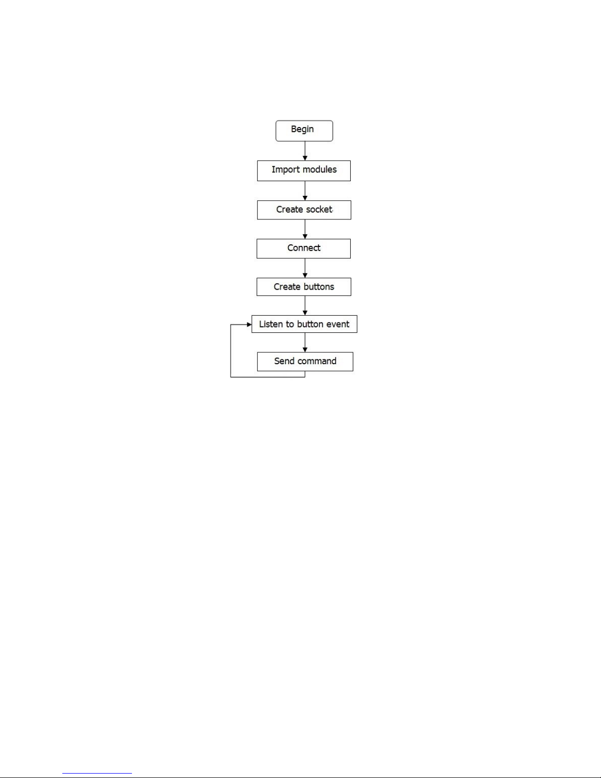
Process Diagram of Client Program
Page 66

64
Summary
In this manual, after the introduction of related components needed for building the
car kit, you've gone through the assembly of the mechanical parts and electrical
modules with the knowledge of Raspberry Pi as well as the key parts like the servo,
Wi-Fi adapter, etc. Also you've learnt a lot of software and coding, which lays a solid
foundation for your future journey of exploring open-source field.
The SunFounder Smart Video Car for Raspberry Pi is not only a toy, but more a
meaningful development kit for Raspberry Pi. After all the study and hands-on
practice of the kit, you should have a better understanding of Raspberry Pi. Now,
just get started to make better work!
 Loading...