

Page 1

Preface
SunFounder
About SunFounder
SunFounder is a technology company focused on Raspberry Pi and Arduino open source
community development. Committed to the promotion of open source culture, we strive to
bring the fun of electronics making to people all around the world and enable everyone to
be a maker. Our products include learning kits, development boards, robots, sensor modules
and development tools. In addition to high quality products, SunFounder also offers video
tutorials to help your own project. If you have interest in open source or making something
cool, welcome to join us! Visit www.sunfounder.com for more!
About This User Manual
The small outdoor racing drone kit SFX190 applies the SF Racing F3 as the flight controller, thus
it gives you all the features you need for the heart of your aircraft. Whether you’re into FPV
racing, acrobatic flying or aerial photography, it’s perfect. In this manual, instructions are
provided on software debugging for the flight controller.
Notes:
1. If you have a components kit, please follow video tutorials under VIDEO on our website
for assembly.
2. If you purchase an assembled one, the software debugging has been configured on
the flight controller originally, which is mentioned in Chapter 2 and Chapter 3. If you want
to redo it, you can follow those instructions.
Safety Precautions
DO FULLY recharge the battery before use, and please install the buzzer alarm in case of
damages caused by over-discharge.
When you fly the quadcopter for the first time, please go to an open environment and
avoid crashing into hard objects in case of quadcopter especially propeller damages.
Free Support
If you have any TECHNICAL questions, add a topic under FORUM section on our website
and we'll reply as soon as possible.
For NON-TECH questions like order and shipment issues, please send an email to
[email protected]. You're also welcomed to share your projects on FORUM.
Page 2

Contents
SunFounder
1. Introduction ..................................................................................................................................... 1
1.1 Get to Know the Aircraft - SFX190 ...................................................................................... 1
1.2 Hardware .............................................................................................................................. 1
1.3 Radio Transmitter Configuration (taking FS-I6X as an example) ................................... 2
1.4 Software ................................................................................................................................ 8
2. Betaflight .......................................................................................................................................... 9
2.1 Installing the Betaflight ........................................................................................................ 9
2.2 Flashing the SF RACING F3 Firmware ............................................................................... 11
2.3 Configuring the Wizard of SF RACING F3 ........................................................................ 16
2.3.1 Calibration ................................................................................................................ 16
2.3.2 Configuration ........................................................................................................... 17
2.3.3 Receiver .................................................................................................................... 18
2.3.4 Configuring Parameter of PID ................................................................................ 20
2.3.5 Configuring the Flight Mode .................................................................................. 21
3. Cleanflight ..................................................................................................................................... 23
3.1 Installing Cleanflight .......................................................................................................... 23
3.2 Flashing SF RACING F3 Firmware ...................................................................................... 25
3.3 Configuring the Wizard of SF RACING F3 ........................................................................ 29
3.3.1 Calibration ................................................................................................................ 29
3.3.2 Configuration ........................................................................................................... 30
3.3.3 Receiver .................................................................................................................... 31
3.3.4 Configuring Parameter of PID ................................................................................ 34
3.3.5 Configuring Flight Mode ......................................................................................... 35
Appendix - Basics for Application ..................................................................................................... 37
Unlocking the Aircraft .................................................................................................................. 37
Control During the Flight.............................................................................................................. 37
Page 3

1. Introduction
SunFounder
1.1 Get to Know the Aircraft - SFX190
1. If you want to flash the firmware, please follow the instructions in Chapter 2 Betaflight or
Chapter 3 Cleanflight.
2. Its frame is made of carbon fiber, which endows it with high tenacity and anti-collision ability.
3. The aircraft provides wonderful stunt flying movements such as left-right flip, crossing, etc.
1.2 Hardware
The SF Racing F3 flight controller is designed to provide high performance flight experience for
the hobbyists. With verified sensor algorithm, it provides incomparable I/O capabilities. The SF
Racing F3 runs a next-generation 32-bit STM32F303CCT6 processor, an MPU6050 accelerometer
and a gyroscope sensor, all high integrated on a lightweight PCB to improve the flight
performance. In addition, it offers more practical functions to your aircraft. The SF Racing F3 flight
controller is perfect whether you are doing FPV contest or practicing stunt flying and it is suitable
for a variety of aircrafts including tricopters, quadcopters, hexacopters, octocopters, fixed wing
aircrafts, etc.
Features
1. The next-generation processor STM32F3 supports high performance floating-point arithmetic
and faster calculation by the ARM Cortex M4 kernel. The looptime for the flight controller is about
2 times of the previous STM32F1.
2. The functions of the I/O ports in the flight controller can be greatly extended and these ports
can be used simultaneously for connecting various devices such as OSD, Smartport, SBUS, GPS,
LED light strip, battery monitor, buzzer, and eight motors.
3. The sixteen PWM I/O cables serve for ESCs, servos and traditional receivers, among which eight
cables work with standard pin headers and the others are distributed in the connectors of the
flight controller.
4. It supports SBUS, SFektrum1024/2048, PPM, PWM and XBus receivers and needs no external
inverter with one already built in.
5. It fully supports the OneShot ESCs for easy PID tuning.
6. The dedicated programmable LED light strip provides a variety of signal lights for the aircraft
heading, racing and night flight.
7. It includes a specific I2C port to connect an OLED display, needless of extra batteries.
8. It provides a battery monitoring port for voltage and current.
9. The buzzer raises the alarm and sends out notification so you can search for the lost aircraft.
10. You can choose from serial wire debug (SWD) and boot mode, so the bootloader will not be
locked.
1
Page 4
11. It uses pin headers, JST-SH sockets or solder pads to wire up. Both angled and straight pin
SunFounder
headers are available.
12. It works with a variety of aircrafts like tricopters, quadcopters, hexacopters, octocopters,
planes, etc.
13. Configuration of the flight controller can be done via a cross-platform GUI
(Windows/OSX/Linux).
Software
The SF Racing F3 runs the open-source Cleanflight flight control software which has an ever-
growing community of friendly developers and users. Being open-source means that you can
contribute to the system.
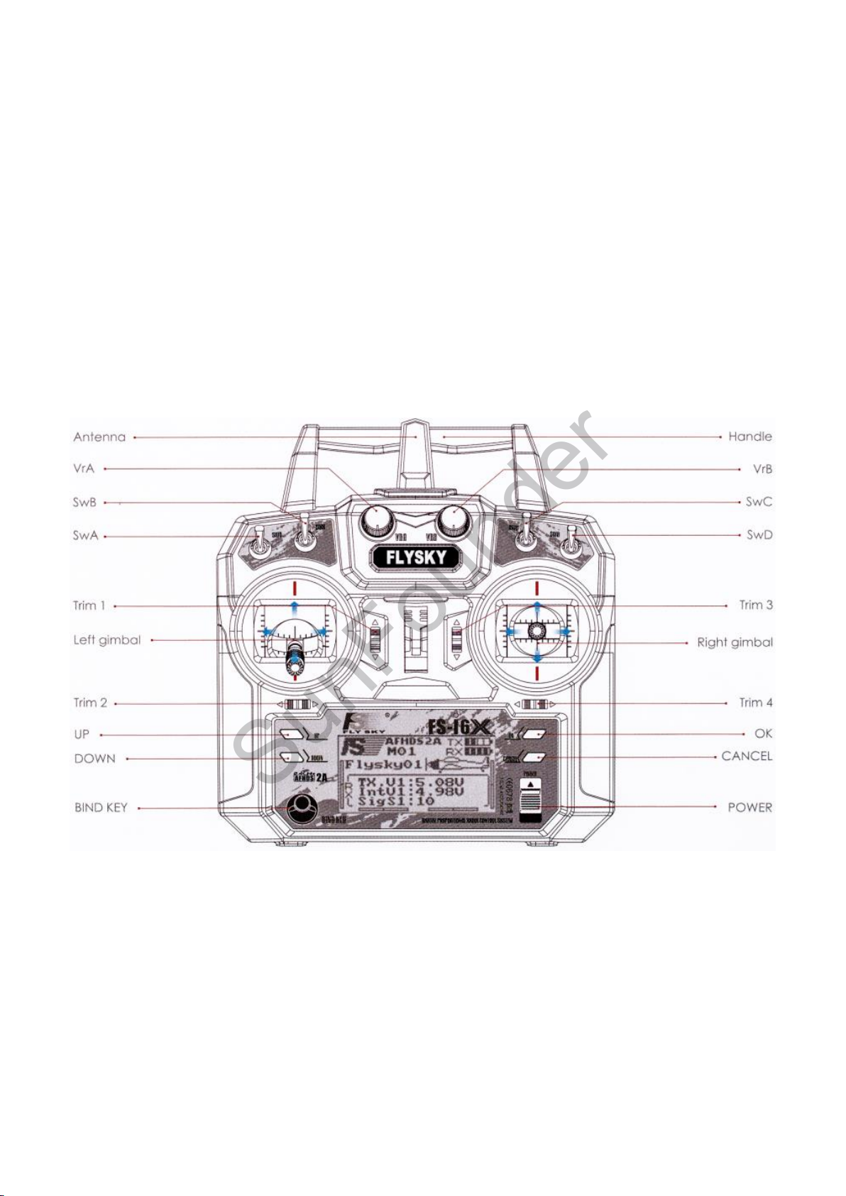
1.3 Radio Transmitter Configuration (taking FS-I6X as an example)
1. Radio Transmitter Overview:
2. Button Functions
To enter the main menu, press and hold the OK button. Use the UP and DOWN button to select
the section and press OK. Then, use the UP and DOWN button to select the submenu and press
again OK. Most of the following screens work similarly:
1) Press OK to select the parameter to modify.
2) Press UP and DOWN to modify the value of the selected parameter.
3) Press and hold CANCEL to exit and save the new parameters.
4) Press CANCEL to exit without saving the new parameters.
To return to the previous screen, press CANCEL. Repeat until it goes back to the main screen.
2
Page 5
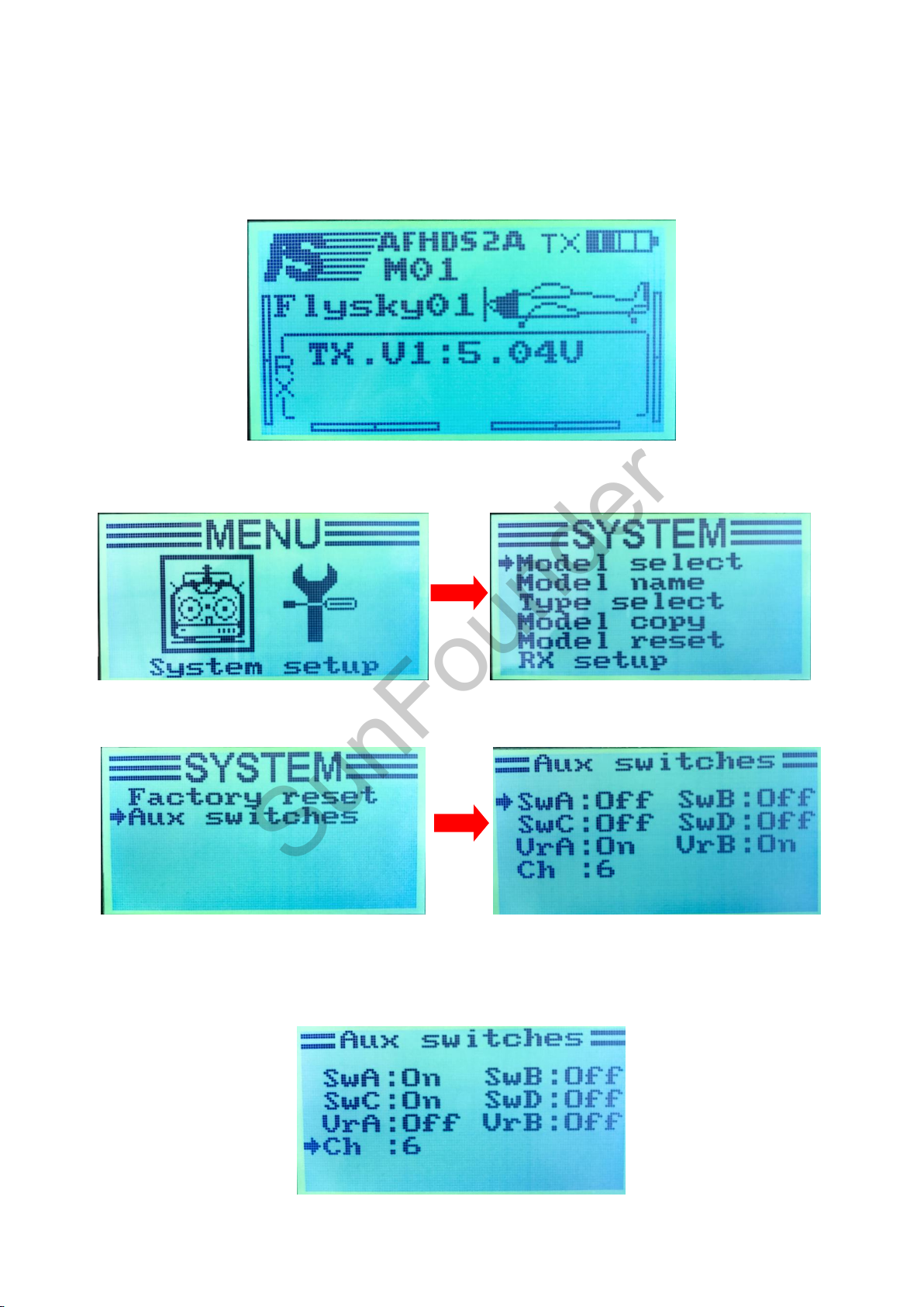
3. Set the radio transmitter to open SWA, SWC auxiliary channel:
SunFounder
The four aux channels SWA, SWB, SWC, and SWD are not used in initial state, and we need to
apply SWA to arm the aircraft and SWC to shift flight mode on the debugged flight controller.
Thus, we need to open the aux channels first.
1) Turn on the transmitter, follow the user manual of the transmitter to operate.
2) Press and hold OK to enter the main menu, and press OK again to select the system setup as
shown below:
Press DOWN, and select AUX switches, and press OK to get into the interface below. Press and
hold OK, and the AUX switches will restore the default setting.
Press OK to select the aux channel, and UP or DOWN to turn it ON or OFF. Here we open two AUX
channels – SWA and SWC, and set Ch as 6 (The transmitter can be set to 6-10 channels; here 6 is
enough). Then press and hold CANCEL to exit and save the setting.
3
Page 6
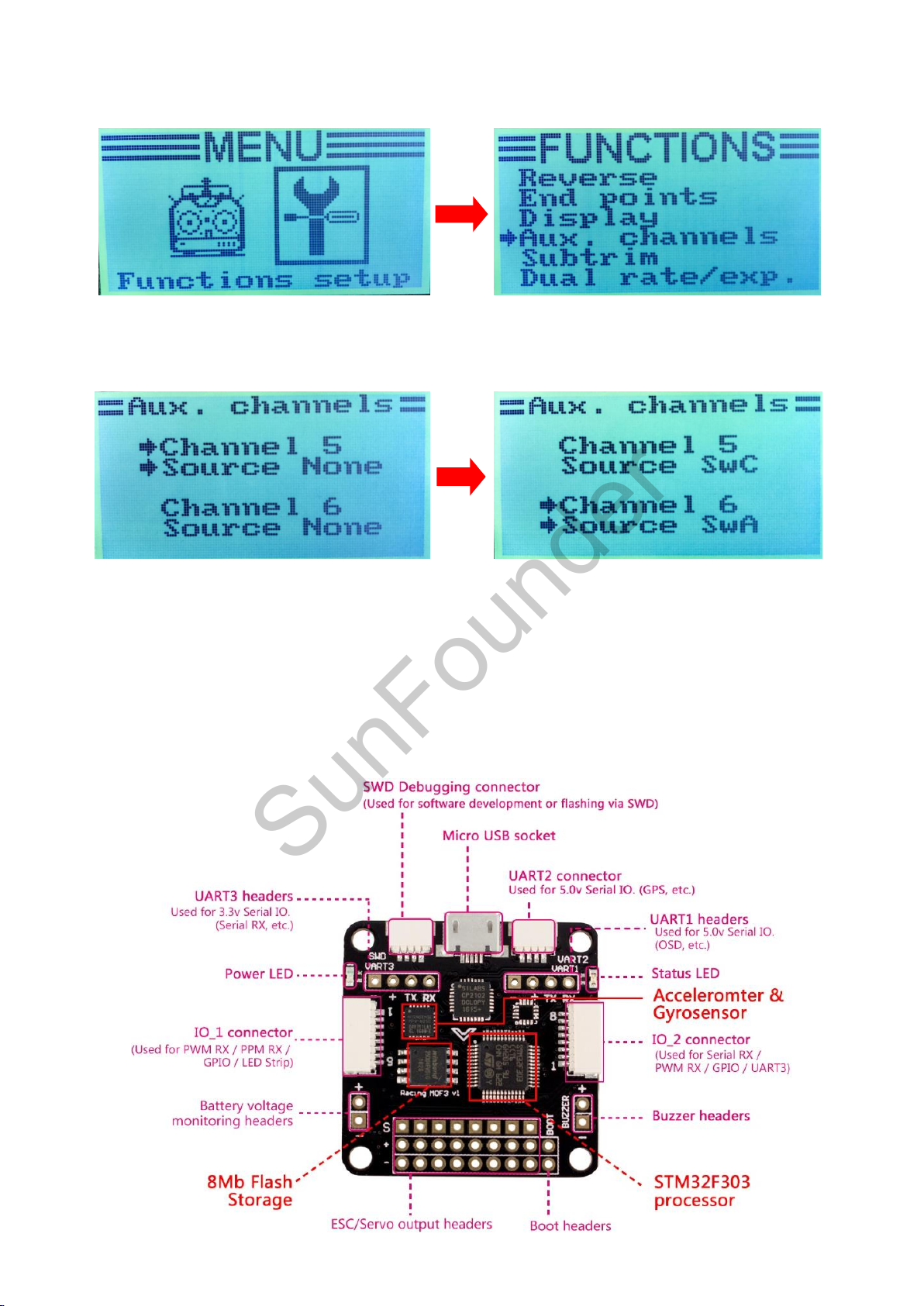
3) Press CANCEL again to go back to the main menu, and UP or DOWN to select Functions setup,
SunFounder
then press OK. Press DOWN to select AUX. channels as shown below:
4) Press OK to get into AUX. channels, and OK to select the channel to be set, then UP or DOWN
to select the corresponding channel. Here we set CH5: SWC; CH6: SWA, then press and hold
CANCEL to exit and save the setting.
5) Press Cancel twice to exit the setting. Now the transmitter configuration is done.
Structure Specification
Dimensions: Board sizing 36 x 36 mm with 3.5mm mounting holes.
Weight: 5.8g
The front:
4
Page 7
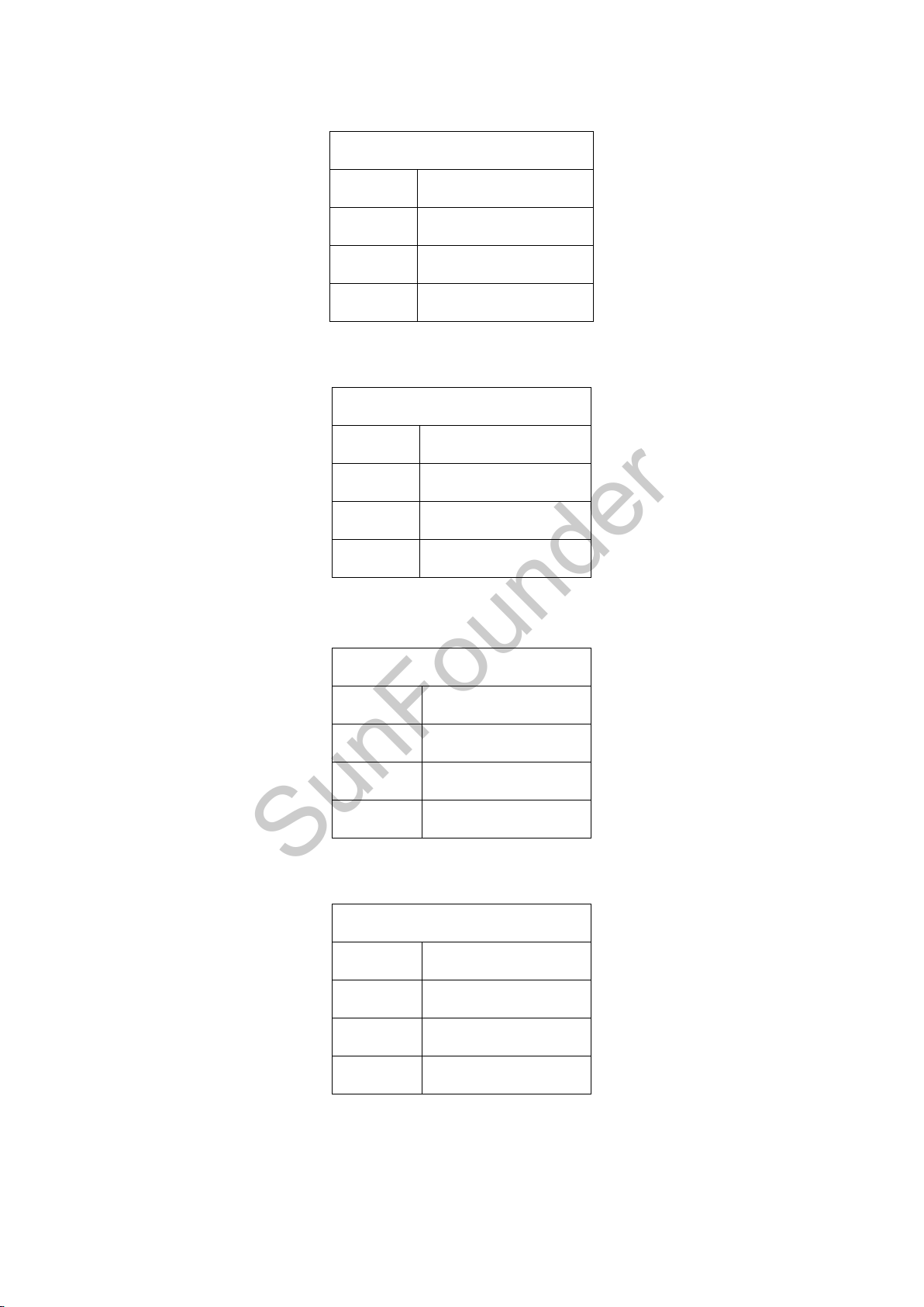
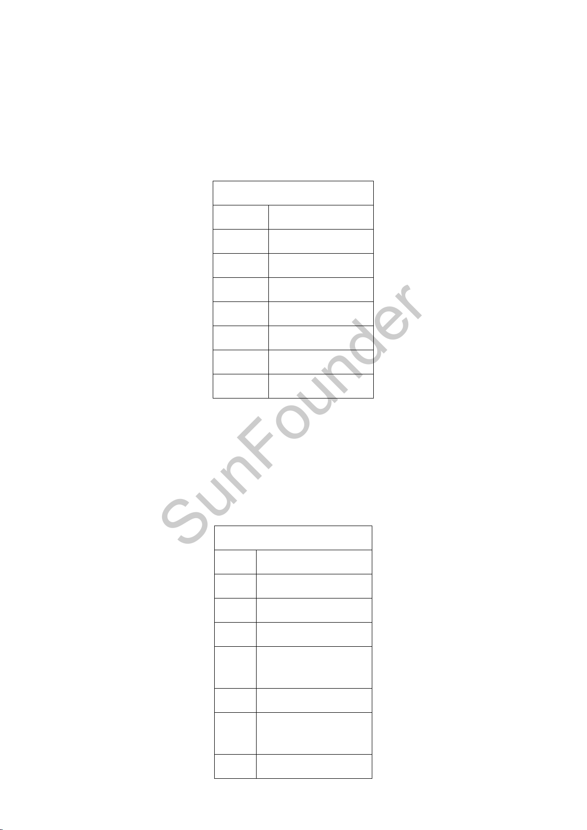
1. SWD debugging connector: To debug the port.
SWD Dedugging
1
GND
2
NRST
3
SWDIO
4
SWDCLK
USART2 Connector
1
GND
2
VCC
3
TXD/SWDCLK
4
RXD
USART3 Headers
1
GND
2
VCC
3
TXD
4
RXD
USART1 Headers
1
GND
2
VCC
3
TXD
4
RXD
SunFounder
Used for software development or flashing via SWD. It cannot be run when USART2 is in use.
2. USART2 connector: Used for the 5V I/O ports (GPS, etc.). It cannot be run when SWD port is in
use.
3. USART3 headers: Used for the 3.3 V I/O ports.
It MUST NOT be used when PWM RX is in use or when it's IO_2 CH3/4.
4. USART1 headers: Used for the 5V I/O ports (OSD, etc.). DO NOT use it when the USB port is
connected.
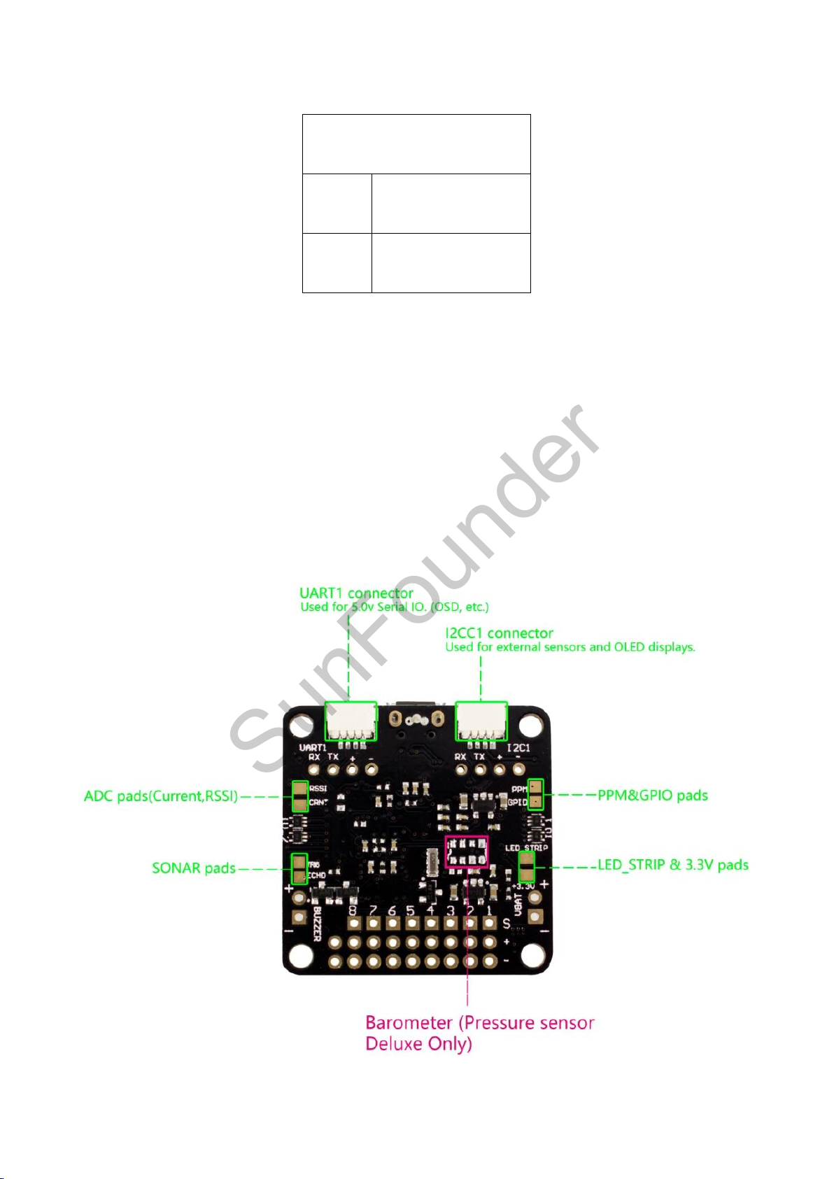
5. IO_1 connector: To connect the PWM RX or PPM RX remote signal mode as well as set the LED
and GPIO.
When using the PWM receiver, connect its CH1, CH2, CH5, and CH6 to pin 3-6 (PWM RX) of the
IO_1 connector respectively.
5
Page 8
Connect it to pin 3 of the IO_1 connector when using a PPM receiver.
IO_1 connector
1
GND
2
VCC
3
CH1/PPM
4
CH2/GPIO
5
CH5/GPIO
6
CH6/GPIO
7
LED_STRIP
8
3.3V
IO_2 connector
1
GND
2
VCC
3
CH3/RXD
4
CH4/TXD
5
CH7/SONAR
TRIGGER
6
CH8/SONAR ECHO
7
ADC_1/Battery
Current Monitoring
8
ADC_2/RSSI
SunFounder
The LED light can be set for battery warning, status indication, flight mode display, etc.
LED Strip data signal can be used to change the color of each LED independently on a strip of
WS2812 RGB LEDs, making it perfect for battery warning lights, orientation lights, indicators, failsafe,
flight mode display, etc.
CH1/2/5/6 can be used as a general purpose I/O if not for PPM/PWM RX.
A 3.3V output is also available.
6. IO_2 connector: Serial RX/PWM RX/GPIO/USART3.
When using a PWM receiver, connect CH3/4/7/8 to PWM RX.
When using a 3.3V serial RX receiver (S.Bus, SUMD/H, etc.), use GND/VCC/CH3 (USART3 RX).
CH3/4/7/8 can be used as general purpose I/O if not for serial/PWM RX.
CH7/8 can be used for a 3.3V sonar sensor when it's not used for PWM RX.
ADC_1/2 can be used to connect the battery current monitoring and RSSI signals (3.3V MAX).
6
Page 9
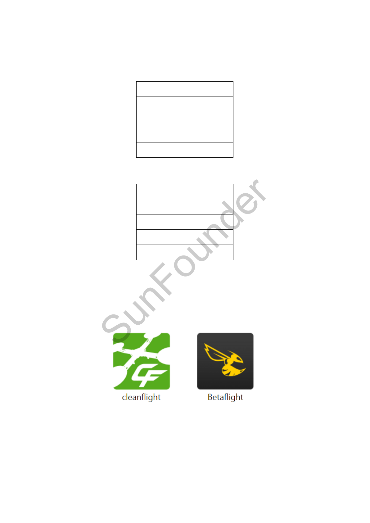
7. Battery voltage monitoring header: To connect the flight controller for battery voltage
Battery voltage monitoring
header
1
-/ Negative pole of
the battery
2
+/ Positive pole of
the battery
SunFounder
monitoring and alarm raising.
8. Buzzer header: To connect the buzzer for alarm and information.
A 50mA 5.0V low-power-consumption buzzer is used for the alarm of low voltage and searching
for lost aircraft in the Cleanflight software.
9. ESC/Servo output headers: To connect eight motors or servos.
It currently supports PWM ESCs (400Hz by default), Oneshot 125 ESCs and PWM servos (50Hz by
default).
10. Boot headers: To recover the firmware.
It runs the STM32 loading program if the soldering pads are bridged; if not, it works normally then.
The back:
7
Page 10
USART1 connector
1
GND
2
VCC
3
TXD
4
RXD
I2C1 connector
1
GND
2
5.0V
3
SCL
4
SDA
SunFounder
11. USART1 connector: Used for 5.0V I/O ports (OSD, etc.)
DO NOT use it when the USB port is connected.
DO NOT use it when the USART1 headers are in use.
12. I2C1 connector: To connect to external sensors and OLED display. SCL and SDA are the signal
ports of the 3.3V.
1.4 Software
The SF Racing F3 runs the Cleanflight and Betaflight flight control software which has a community
with a growing number of friendly developers and users. Being open-source means that you can
also contribute to the system.
8
Page 11
2. Betaflight
SunFounder
2.1 Installing the Betaflight
Step 1: Run the Google Chrome
You will see the interface as shown below:
Step 2: Click on the Customize and Control Google Chrome button at the top right of the window,
then on the drop-down list select More Tools -> Extensions:
9
Page 12
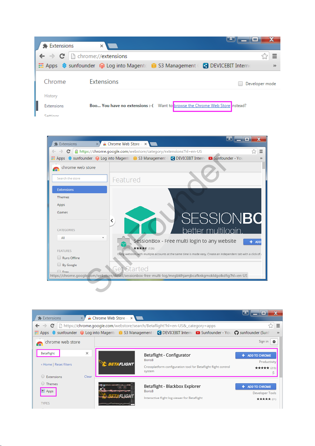
Step 3: On the window, click browse the Chrome Web Store.
SunFounder
And you'll see the shop page as below:
Step 4: Type in Betaflight in the search bar, select Apps and press Enter. You will see the Betaflight
app.
10
Page 13
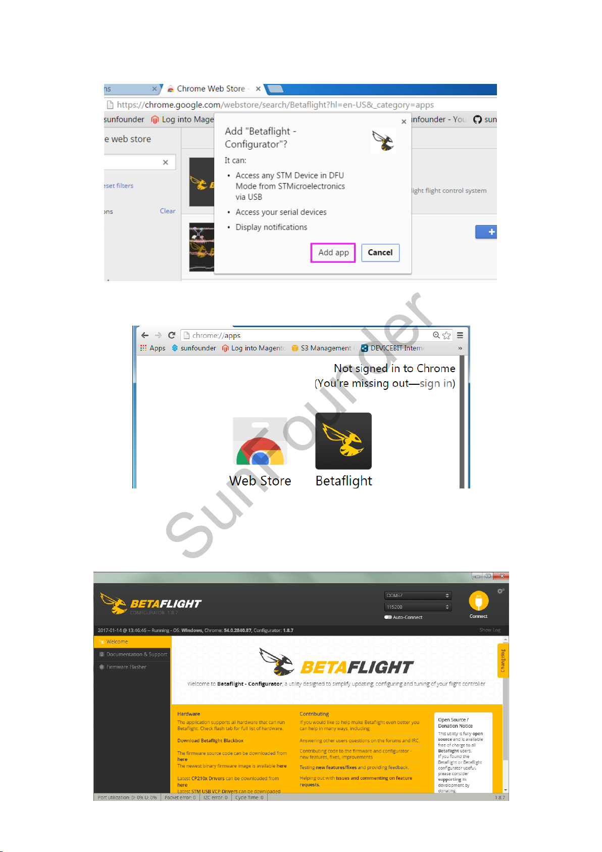
Step 5: Click + ADD TO CHROME, and a prompt Add "Betaflight - Configurator" will pop up asking
SunFounder
you whether to add the extension or not. Just click Add app.
Step 6: The software installation may take a little time. When it is done, you will see the Betaflight
app in Chrome Extensions.
2.2 Flashing the SF RACING F3 Firmware
Step 1: Click Betaflight to run the ground control software (GCS).
11
Page 14
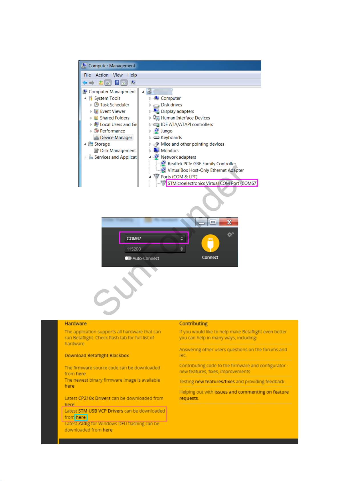
Step 2: Connect the SF RACING F3 to the computer with a USB cable. Go to Computer
SunFounder
Management -> Device Manager -> Ports (COM & LPT) to check whether the SF RACING F3 is
recognized by the computer or not.
Step 3: If YES, choose the corresponding COM port at the top right corner on the software.
Do not connect now.
Step 4: If there is NO driver software on your computer, please install the driver first.
Note: If the flight controller is recognized by the computer, please skip this step.
1) The SF RACING F3 flight controller applies STM32 Virtual COM Port (VCP). You can download
this driver in Betaflight.
12
Page 15
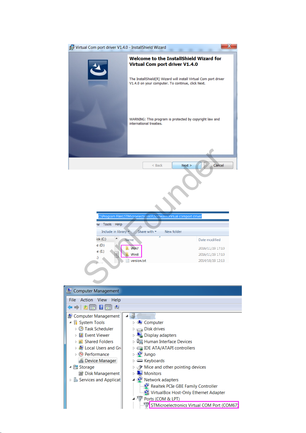
2) After download the driver, double-click VCP_V1.4.0_Setup.exe to install it. After it's
SunFounder
completed (click Close), please CONTINUE the installation below.
3) Get into C:\Program Files (x86)\STMicroelectronics\Software\Virtual comport
driver\Win8\ - Here type in Win7 or Win8 for your computer’s operating system. You can see
there are two files. If your system is 64-bit, please click dpinst_amd64 to install; if it is 32-bit,
click dpinst_x86. Wait until the installation is completed.
4) Replug in the USB cable, and then you can see the flight controller is recognized by the
computer in the Device Manager.
13
Page 16
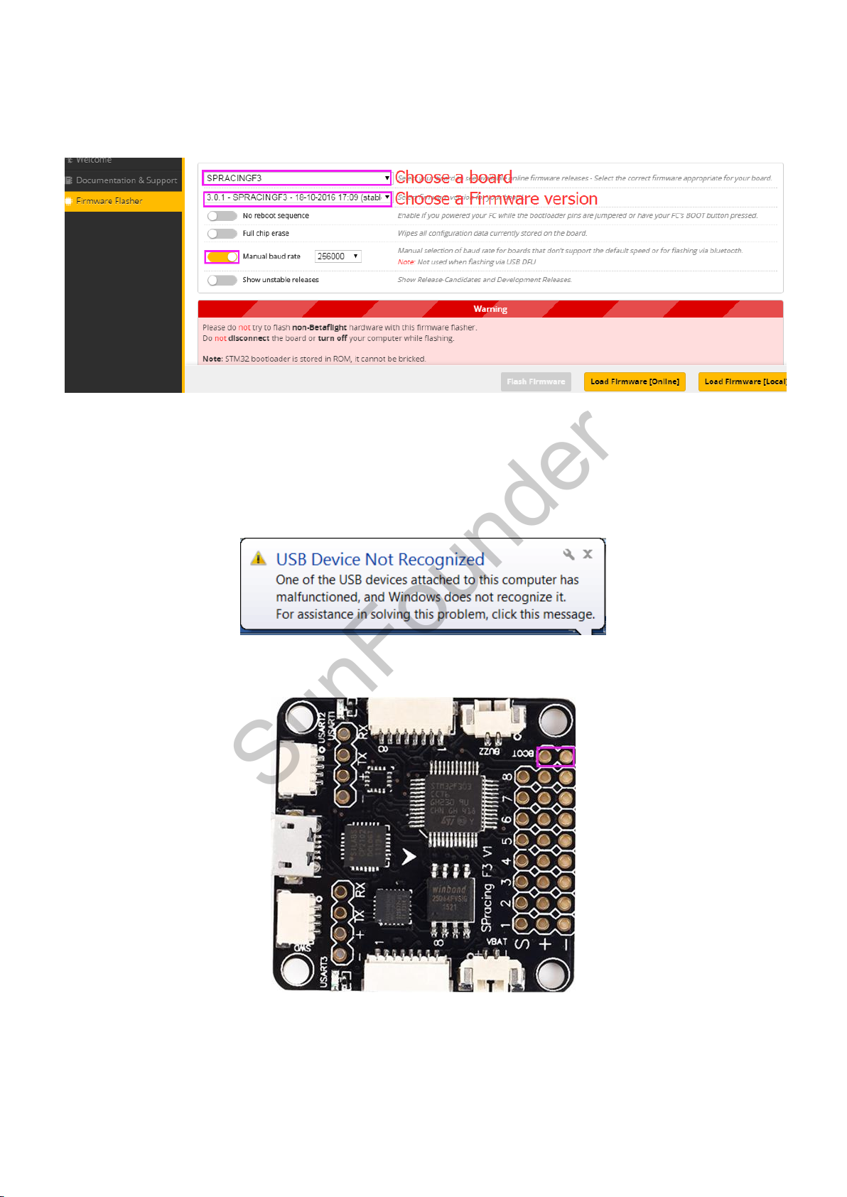
Step 5: Click Firmware Flasher (you can see the icon’s name on the left by amplifying the
SunFounder
Betaflight) to upgrade and flash the firmware. Choose a board: SPRACINGF3; Choose a latest
firmware version: XXXXX; Enable the “Manual baud rate” and select the baud rate 256000.
Step 6: There are two Load Firmware options: Load Firmware[Online] and Load Firmware[Local] -
you are recommended to select Load Firmware[Online].
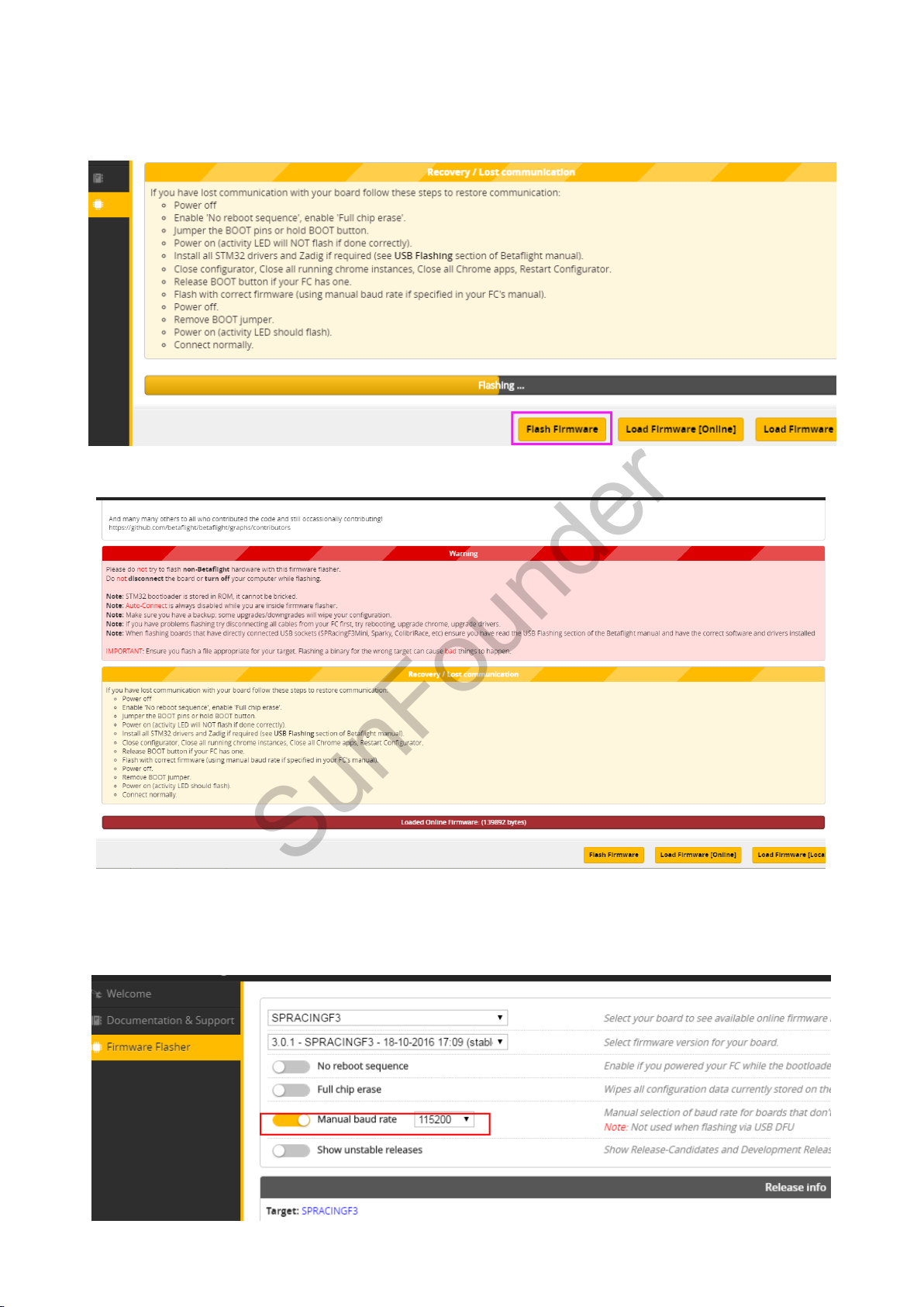
Step 7: After loading, click Flash Firmware to start flashing. Wait for Flash Firmware completed.
Note: DO NOT pull out the USB cable during the firmware flashing, or you will get an error “USB
Device Not Recognized” when you replug in the USB cable.
1) Thus, you need to pull out the USB cable, and use the tip of a tweezer or a screw driver to
connect the two BOOT pads (as shown below) for a while.
14
Page 17
SunFounder
2) Then insert the USB cable, and reopen the Betaflight. Click Flash Firmware again, and it
should be flashed successfully after a while.
Note: If the flash goes wrong, the following page will appear:
Solution: Disconnect the USB cable from the computer. Connect the two soldering pans beside
BOOT on the board with a wire, then plug back the USB cable, and take away the wire. In the
software, decrease the baud rate. And click Flash Firmware again.
15
Page 18
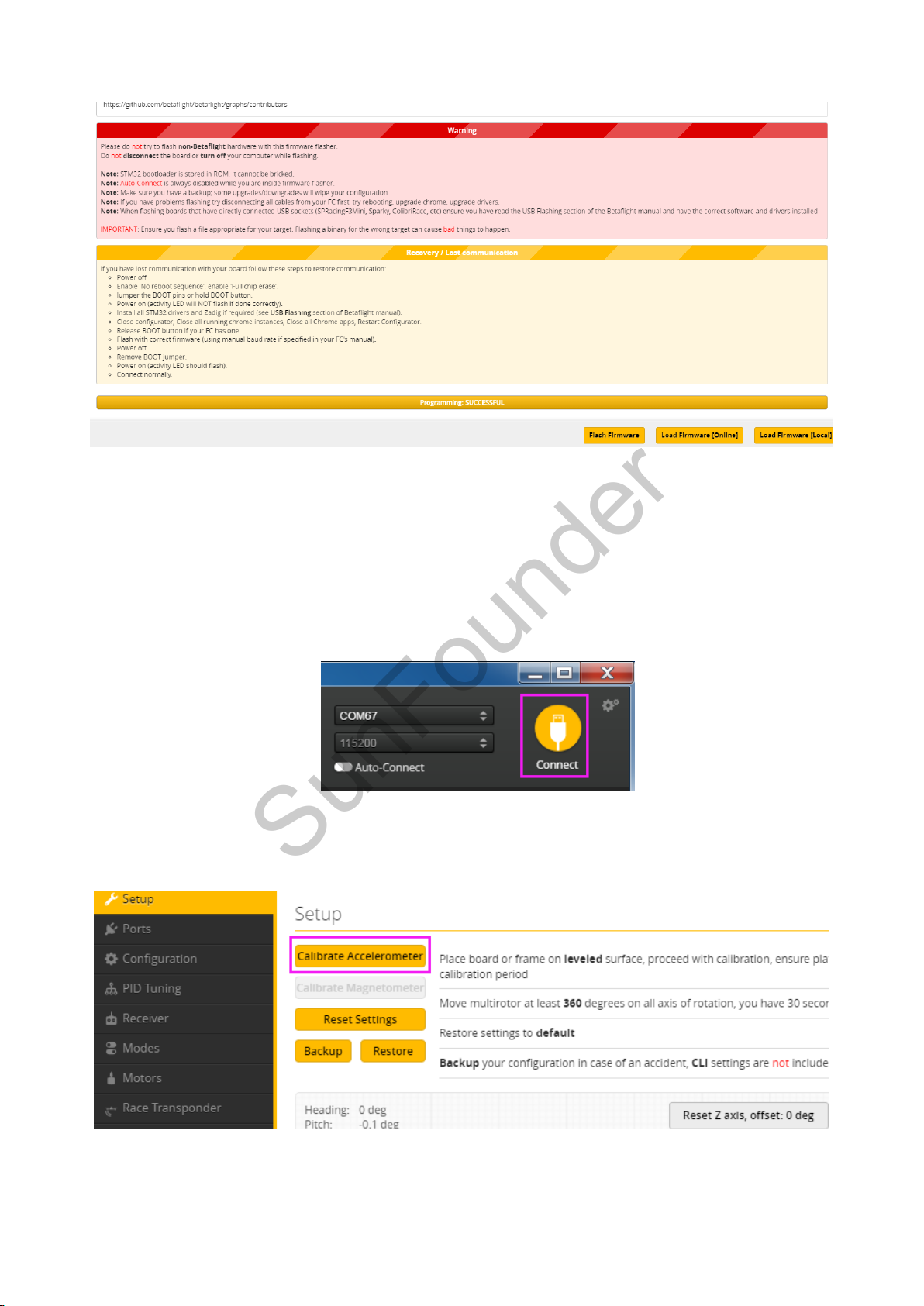
If the flash goes successfully, the following page will be shown:
SunFounder
2.3 Configuring the Wizard of SF RACING F3
2.3.1 Calibration
1) Calibrating the Accelerometer
Click Connect at the top right of the software.
Place the SF RACING F3 on a level surface, click Calibrate Accelerometer for calibrating
horizontally. There is no need to calibrate the compass. If the arrow in the software does not face
the front of the aircraft, just replug the USB cable to try.
2) Calibrating the ESCs
Click Motors on the left, then click switch in frame “1” to activate Enable motor control. Next,
slide the Master switch in frame “2” to the max, and connect the battery to the plane (REMOVE
16
Page 19
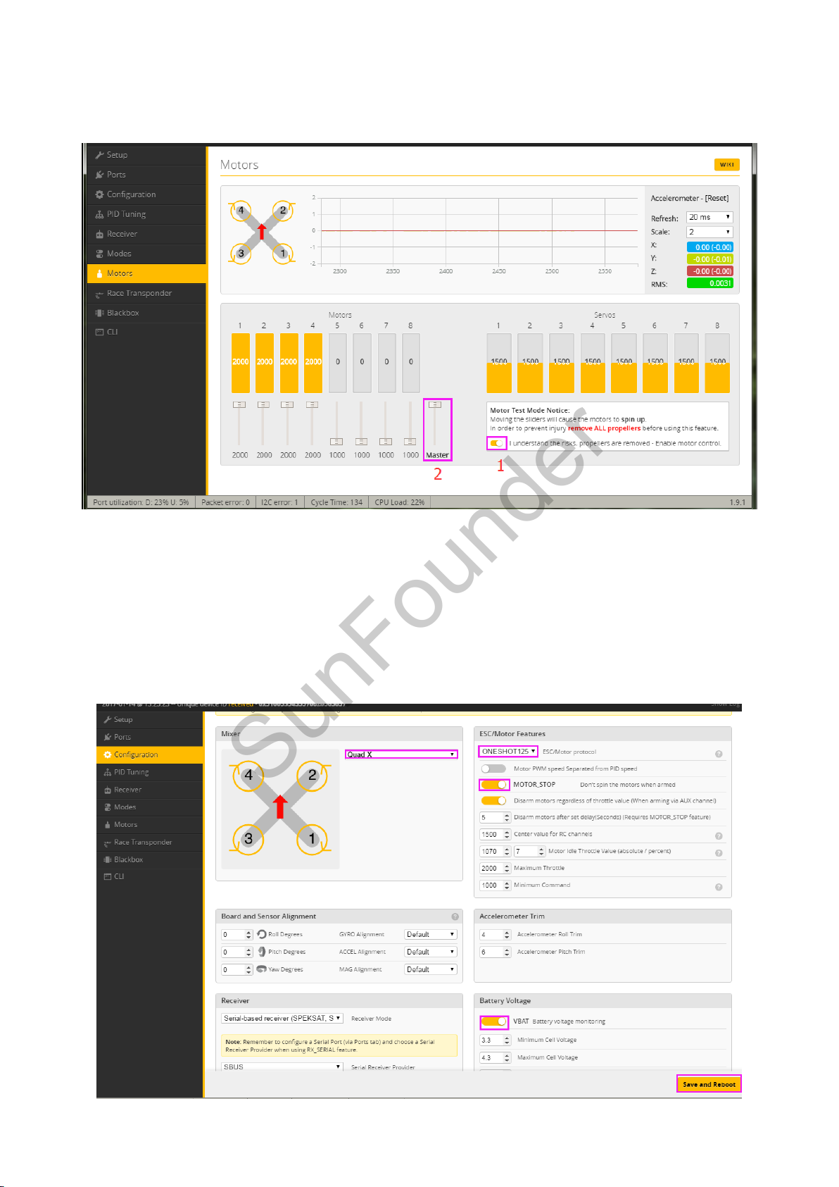
the propellers before connecting it to power.). When a beeping from low to high is heard, slide
SunFounder
the Mater switch to the Min; then a beeping from high to low, slide the Master switch slowly to
adjust. When the motors spin, the calibrating is completed.
After the ESC’s calibrating is done, slide Master to the lowest, and inactivate "1" to disconnect
the battery from the aircraft.
2.3.2 Configuration
Click Configuration on the left to set Quad-X as default mode in Mixer, and select ONESHORT125
and click to activate MOTOR_STOP in ESC/Motor Features; Activate VBAT in Battery Voltage part,
then remember to click Save and Reboot after setting.
17
Page 20
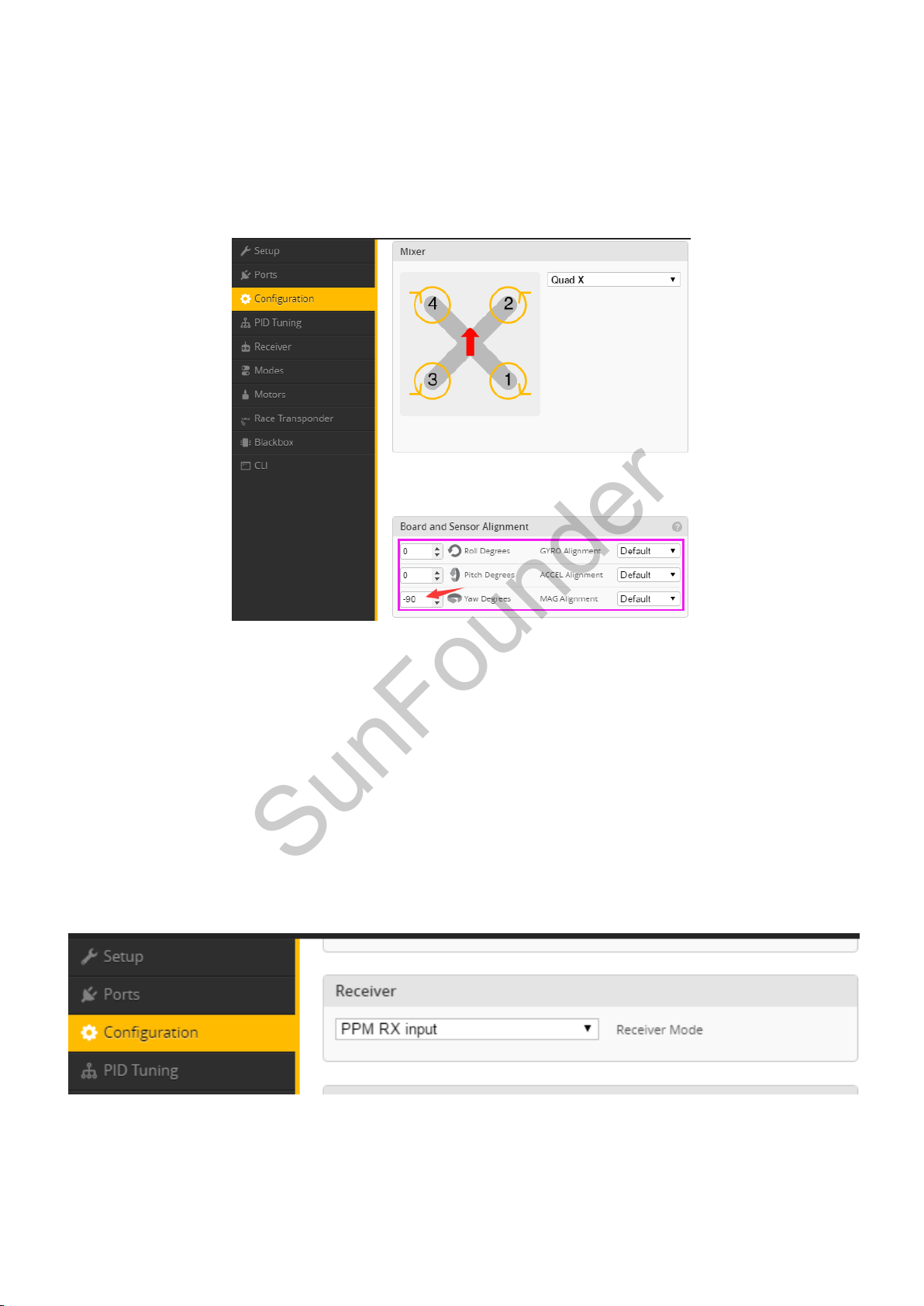
Under Board and Sensor Alignment, you can set the orientation of the arrow of the flight
SunFounder
control SF RACING F3. The arrow of our board points to 90 degrees clockwise from the plane
head orientation, or if you take the front of the plane, it points to your right. Therefore, set –90
for Yaw Degrees. Place the flight control with the arrow at the position of 90 degrees anti-
clockwise from the aircraft head, and set 90 for Yaw Degrees; place it with the arrow right at
the head, set it as 0.
After setting, click Save and Reboot to save it.
2.3.3 Receiver
The SF RACING F3 supports PPM, SBUS, and DSM/DSMX; thus you can set your receiver to these
modes.
PPM Signal Mode
The receiver is set under the PPM signal mode originally. Under this mode, the least serial ports are
occupied and the LED indicator can be set. Here PPM is set as the default RX signal input in
Betaflight. So if your receiver is in the PPM signal mode, there is no need to change the setting of
Receiver Mode in Betaflight.
SBUS Signal Mode
1) If your receiver is in the SBUS signal mode, click Ports on the left and activate Serial RX
in UART3, and then click Save and Reboot.
18
Page 21

SunFounder
2) Next, click Configuration on the left, select Serial-based receiver as Receiver Mode, and select
SBUS in Serial Receiver Provider.
DSM Signal Mode:
1) If your receiver is in the DSM/DSMX signal mode, click Ports and enable Serial RX in UART3,
then click Save and Reboot.
2) Click Configuration, select RX_SERIAL as Receiver Mode, and select SPEKTRUM1024 in Serial
Receiver Provider.
19
Page 22
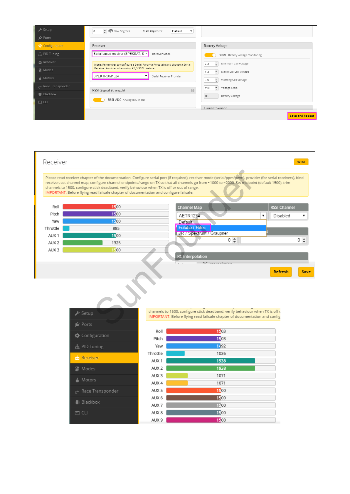
After setting, click save and Reboot to save it.
SunFounder
3) Click Receiver on the left, select Futaba/Hitec for Channel Map. Click Save.
Now, click Receiver on the left, pick up the radio transmitter and pull the rocker of throttle or yaw,
and you will see the change of channels related as shown below.
2.3.4 Configuring Parameter of PID
Click PID Tuning, and you will see the PID value and RC rate of different channels. You do not
need to modify them. PID (Proportional Integral Derivative) is used to adjust the flight
20
Page 23
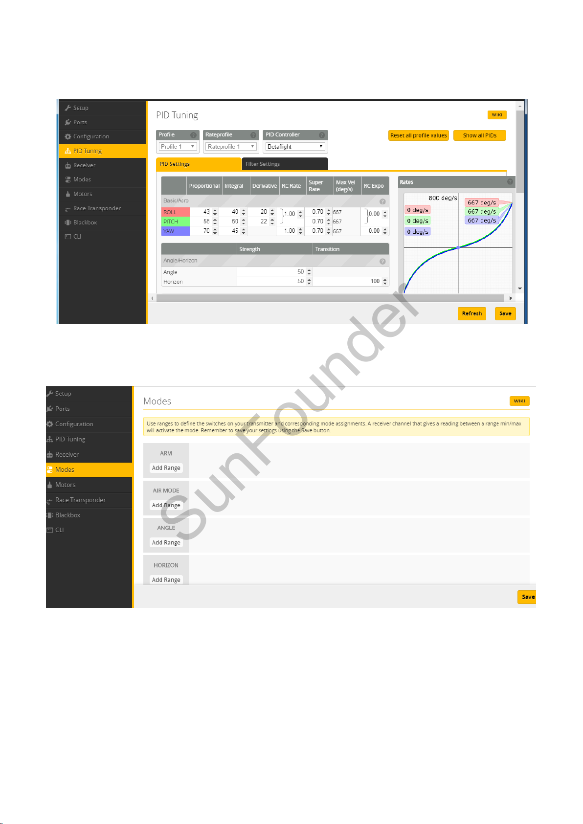
performance. By default, the plane flies mildly, which will respond to the control a little slower.
SunFounder
You can adjust the PID parameters to get a more agile flight. If you are a beginner, you are not
recommended to do so.
2.3.5 Configuring the Flight Mode
Click Modes on the left to configure the flight mode.
1) Set the self-stabilization mode, horizontal mode and manual mode
You need to choose a 2-channel or 3-channel AUX x, set the self-stabilization mode, horizontal
mode, and manual mode to be controlled all by AUX x, and then set the volume for three modes
in Betaflight. For example, here we choose the 3-channel AUX1 to control these three modes.
Click Add Range in AIR MODE to run the manual mode. Select AUX1 and the value ranging from
1700 to 2100.
Click Add Range in ANGLE to run the self-stabilization mode. Select AUX1 and the value ranging
from 900 to 1300.
21
Page 24
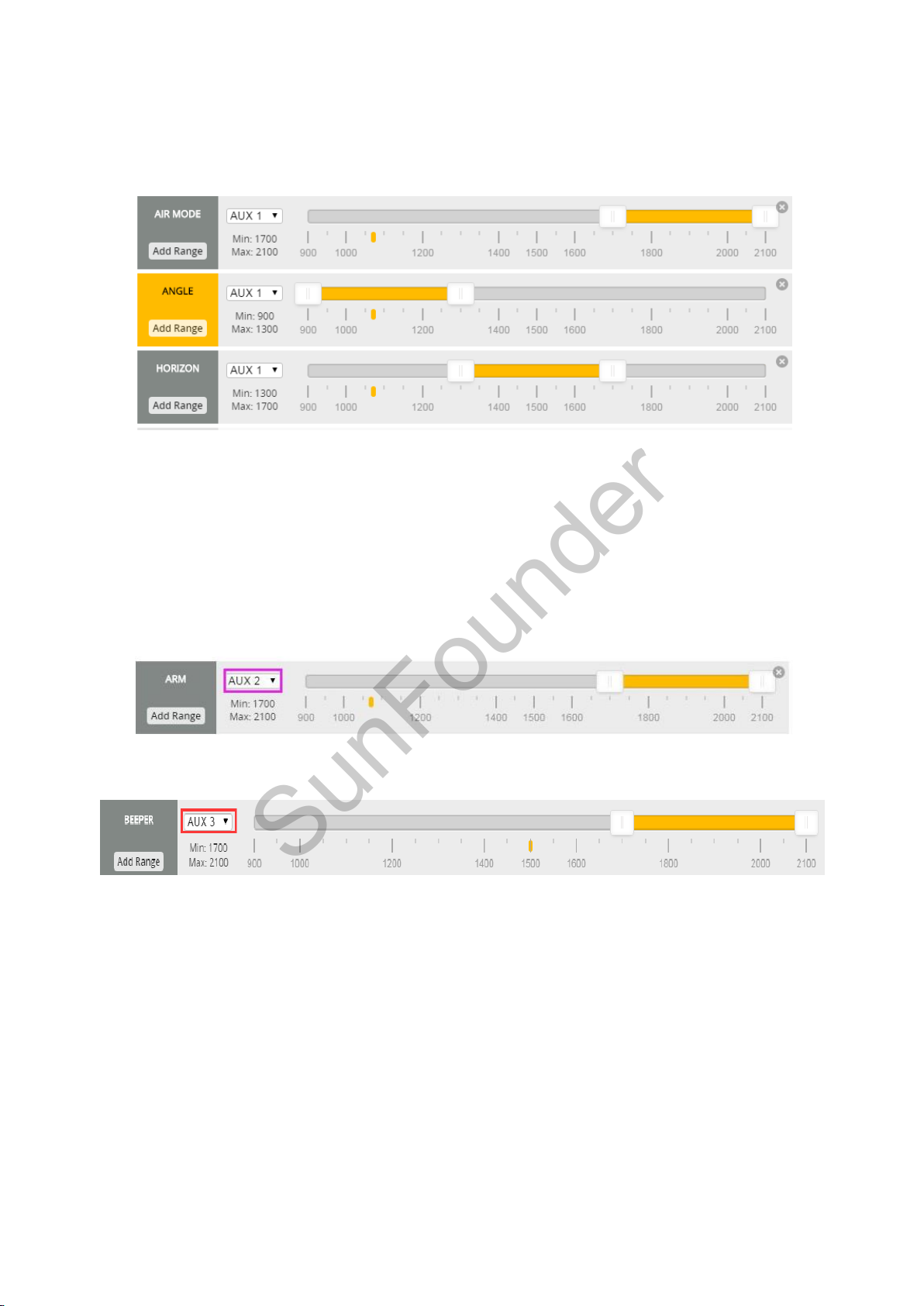
Click Add Range in HORIZON to run the horizontal mode. Select AUX1 and the value will be 1300
SunFounder
to 1700.
You can set the ranges for different modes yourself. Try to slide the switch for each mode and
check whether the range changes or not.
Remember to click Save after modifying. If you don’t have a 3-channel AUXx, you can choose
two modes from three.
2) Set the ARM/DISARM mode and alarm mode
Choose an AUX x to control the ARM/DISARM Mode of the aircraft. For example, here we choose
AUX2.
Click Add Range in ARM to set ARM/DISARM modes, and select AUX2 and the value ranging from
1700 to 2100.
Click Add Range in BEEPER to set the buzzer alarm, and select AUX3 and the value ranging from
1700 to 2100.
Click Save to save the settings.
After all the settings, click Disconnect at the top right of the software to break the connection
with the SF RACING F3.
22
Page 25
3. Cleanflight
SunFounder
3.1 Installing Cleanflight
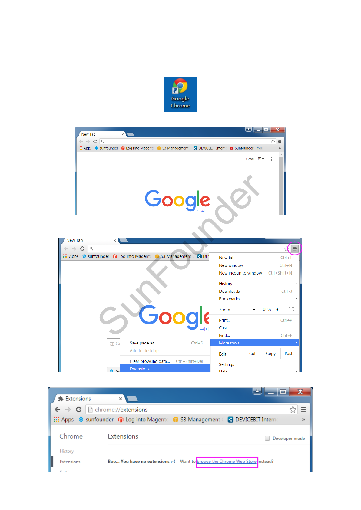
Step 1: Run the Google Chrome
And you will see the interface as shown below:
Step 2: Click on the Customize and Control Google Chrome button at the top right of the window,
and then on the drop-down list select More Tools -> Extensions.
Step 3: Click browse the Chrome Web Store.
23
Page 26
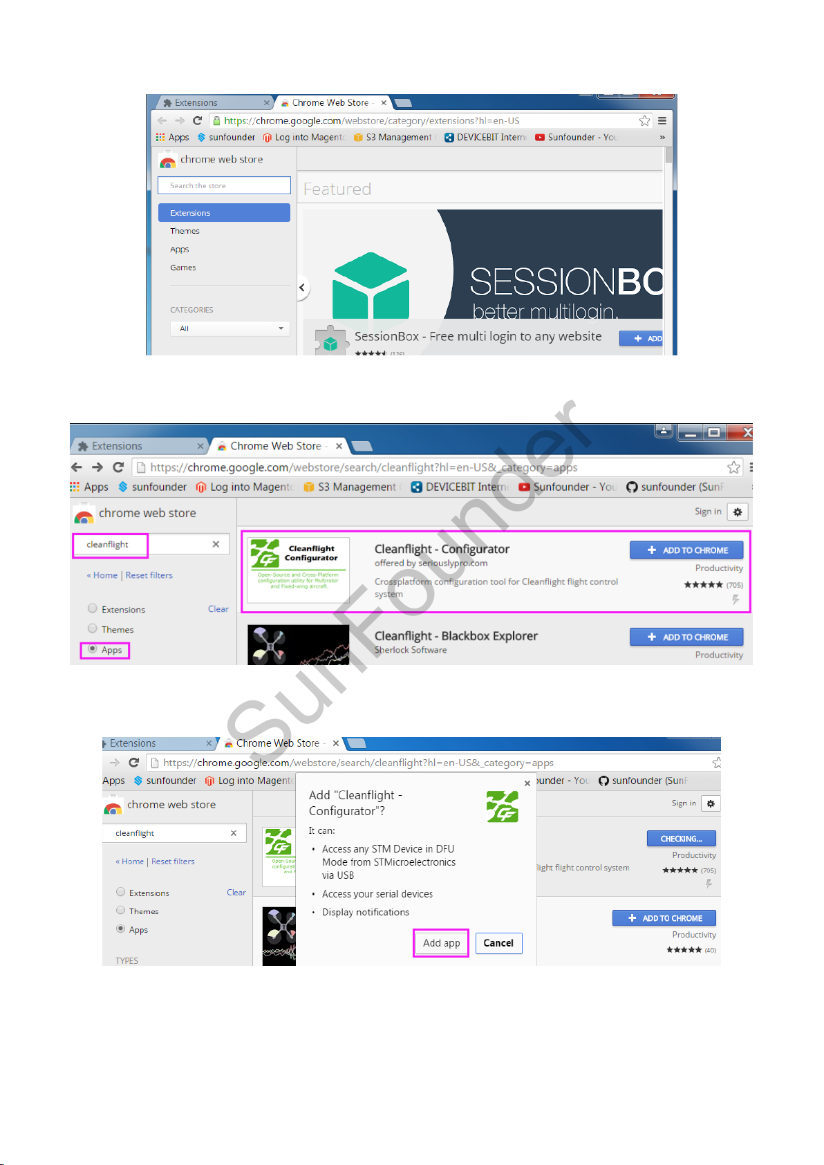
And you'll see the shop page as below:
SunFounder
Step 4: Type in Cleanflight in the search bar and select Apps, and you will see the Cleanflight
App.
Step 5: Click + ADD TO CHROME. A prompt Add "Cleanflight - Configurator" will pop up, and then
click Add app to install.
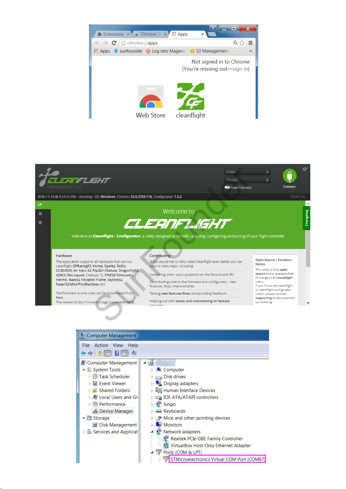
Step 6: The software installation may take a little time. When it is done, you will see the Cleanflight
app in Chrome Apps.
24
Page 27
SunFounder
3.2 Flashing SF RACING F3 Firmware
Step 1: Click Cleanflight to run this ground control software.
Step 2: Connect the SF RACING F3 to the computer with a USB cable. Open the Device Manager
to check whether the SF RACING F3 is recognized by the computer or not.
25
Page 28
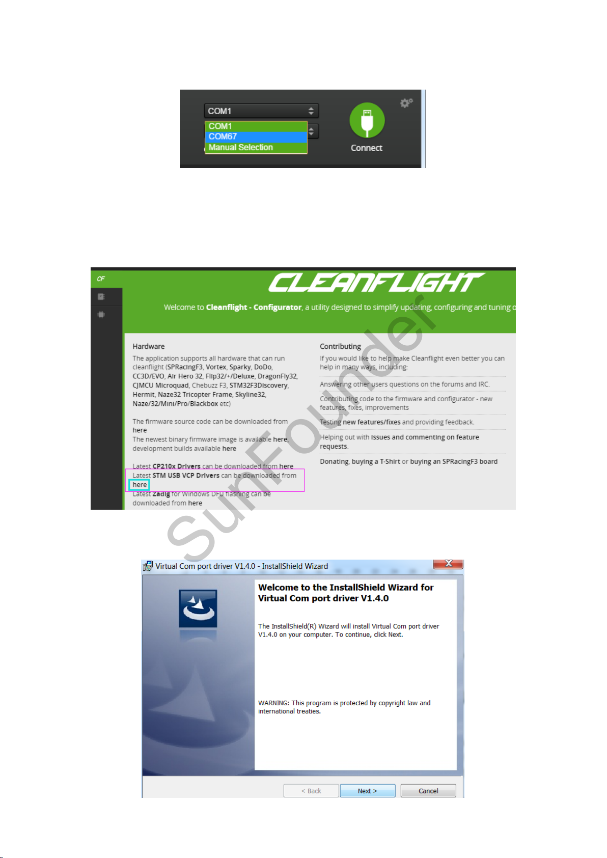
Step 3: If yes, choose the corresponding COM port at the top right of the software. Do not click
SunFounder
connect now.
Step 4: If there is no driver software on your computer, you need to install the driver first.
Note: If the flight controller is recognized by the computer, please ignore this step.
1) The SF RACING F3 flight controller applies STM32 Virtual COM Port (VCP). You can download
this driver in Cleanflight.
2) After downloading the driver, double-click VCP_V1.4.0_Setup.exe to install it. After it's
completed (click Close), please CONTINUE the installation below.
26
Page 29
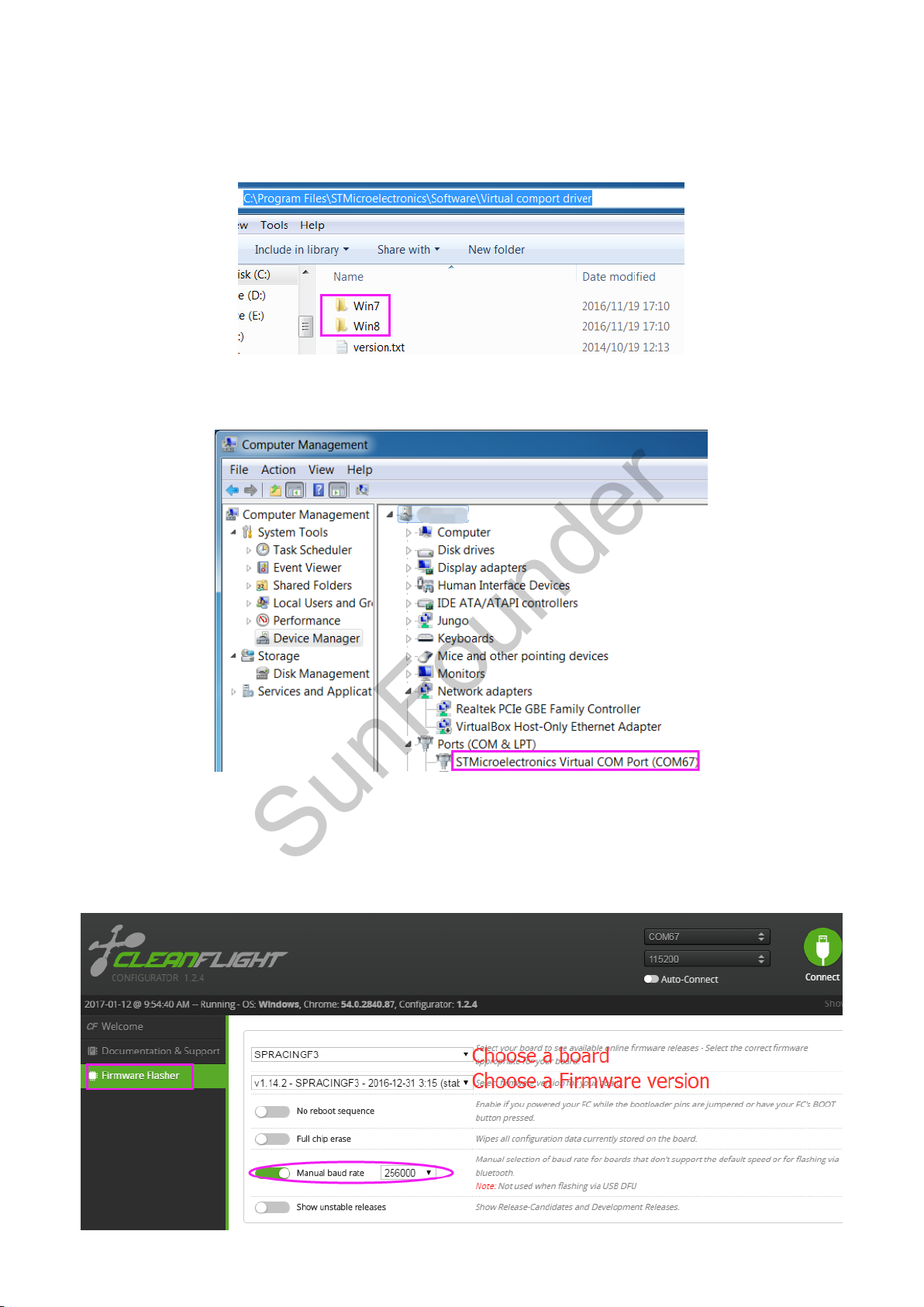
3) Get into C:\Program Files (x86)\STMicroelectronics\Software\Virtual comport driver\Win7 or
SunFounder
Win8 (here type in Win7 or Win8 according to your computer’s operating system). You can
see there are two files. If your system is 64-bit, please click dpinst_amd64 to install; if it is 32-bit,
please choose dpinst_x86. Wait until the installation is completed.
4) Replug the USB cable, and then you can see the fight controller is recognized by the
computer in the Device Manager.
Step 5: Click Firmware Flasher (you can see the icons’ name on the left by amplifying the
Cleanflight logo) to upgrade and flash the firmware. Choose a board: SPRACINGF3; Choose a
latest firmware version: XXXXX (based on the actual situation); Enable Manual baud rate and
select the baud rate 256000.
27
Page 30
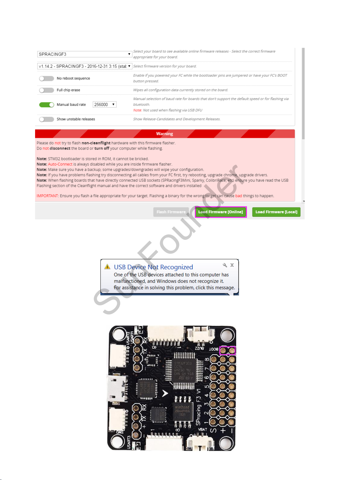
Step 6: There are two Load Firmware options: Load Firmware[Online] or Load Firmware[Local], you
SunFounder
are recommended to select Load Firmware[Online].
Step 7: After loading, click Flash Firmware to start flashing. Wait for the flash being done.
Note: Do not pull out the USB cable during firmware flash, or you will get an error “USB Device Not
Recognized” if you reinsert the USB cable.
Thus, you need to pull out the USB cable, and use the tip of a tweezer or a screw driver to connect
the two BOOT pads (as shown below) for a while.
28
Page 31
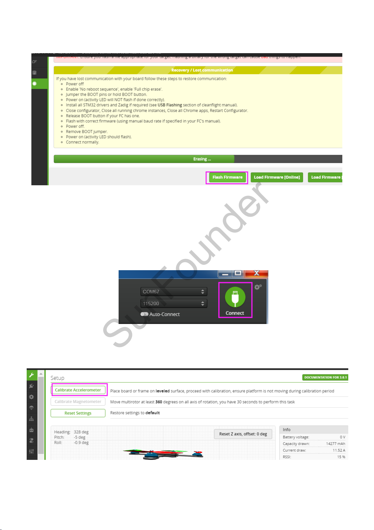
Then insert the USB cable, and reopen the cleanflight. Click Flash Firmware again. It will be flashed
SunFounder
successfully after a while.
3.3 Configuring the Wizard of SF RACING F3
3.3.1 Calibration
1) Calibrating the Accelerometer
Click Connect at the top right of the software.
Place the SF RACING F3 on a level surface, click Calibrate Accelerometer to proceed calibrate
horizontally. There is no need to calibrate the compass. If the arrow in the software does not face
the front of the aircraft, just replug the USB cable to try.
2) Calibrating the ESCs
Click Motors on the left, then click switch in frame “1” to activate Enable motor control. Next,
slide the Master switch in frame “2” to the max, and connect the battery to the plane (REMOVE
29
Page 32
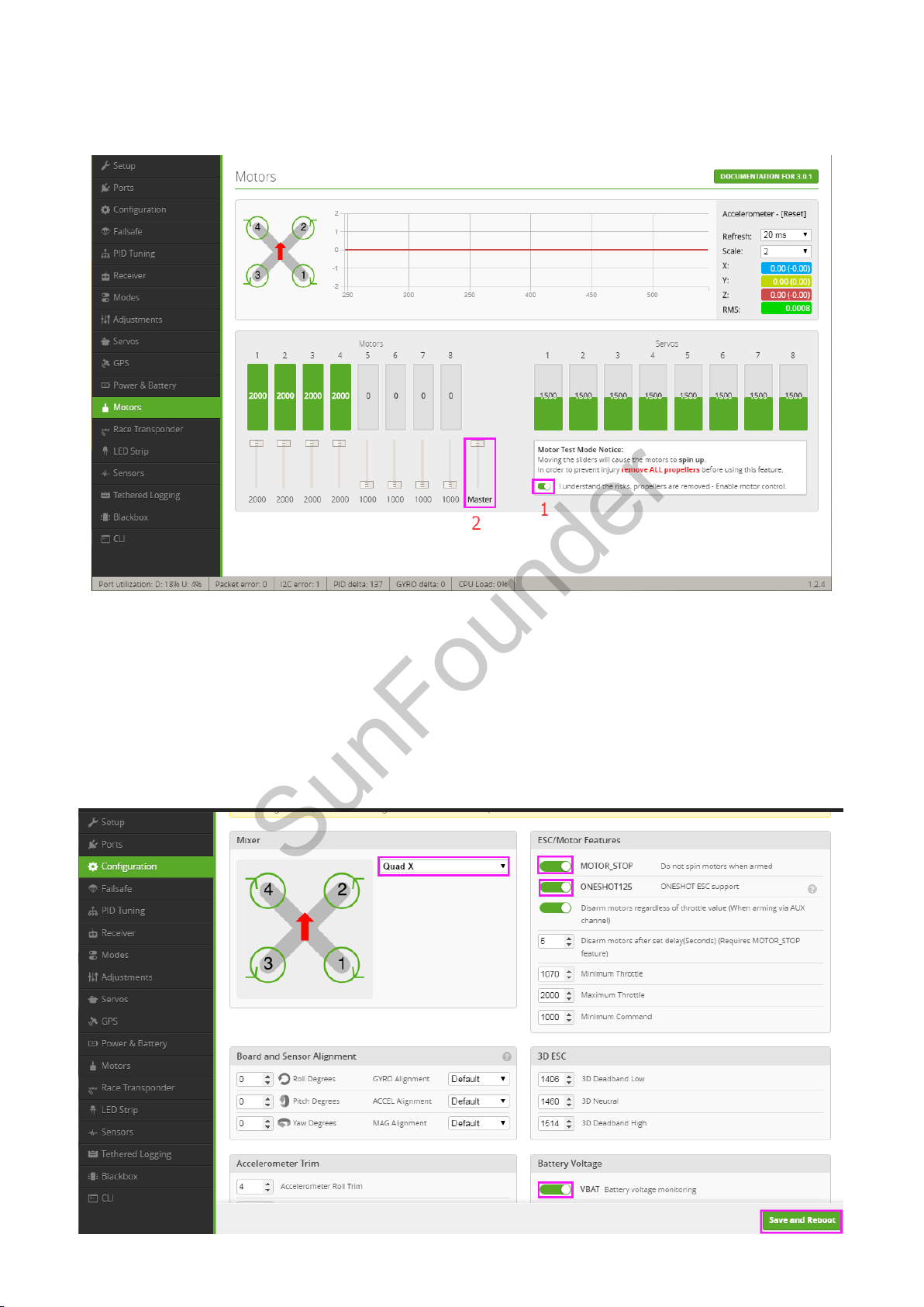
the propellers before connecting it to power.). When a beeping from low to high is heard, slide
SunFounder
the Mater switch to the Min; then a beeping from high to low, slide the Master switch slowly to
adjust. When the motors spin, the calibrating is completed.
After the ESC’s calibrating is done, slide Master to the lowest, and inactivate "1" to disconnect
the battery from the aircraft.
3.3.2 Configuration
Click Configuration on the left to configure Quad-X as default mode in Mixer, enable
MOTOR_STOP in ESC/Motor Features and VBAT in Battery Voltage part, and then remember to
click Save and Reboot after setting.
30
Page 33
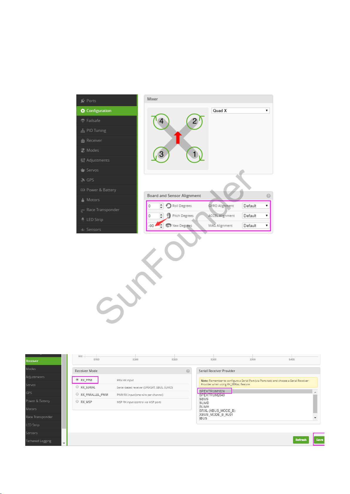
Under Board and Sensor Alignment, you can set the orientation of the arrow of the flight control
SunFounder
SF RACING F3. The arrow of our board points to 90 degrees clockwise from the plane head
orientation, or if you take the front of the plane, points to your right. Therefore, set –90 for Yaw
Degrees. Place the flight control with the arrow at the position of 90 degrees anti-clockwise from
the aircraft head, and set 90 for Yaw Degrees; place it with the arrow right at the head, set it as
0.
After setting, click Save and Reboot to save it.
3.3.3 Receiver
The SF RACING F3 supports PPM, SBUS, and DSM/DSMX; thus you can set your receiver to these
modes.
PPM Signal Mode
The receiver is set under the PPM signal mode originally. Under this mode, the least serial ports are
occupied and the LED indicator can be set.
Here PPM is set as default RX signal input in Cleanflight. If your receiver is in the PPM signal mode,
there is no need to change the setting of Receiver Mode and Serial Receiver Provider.
31
Page 34
SunFounder
SBUS Signal Mode
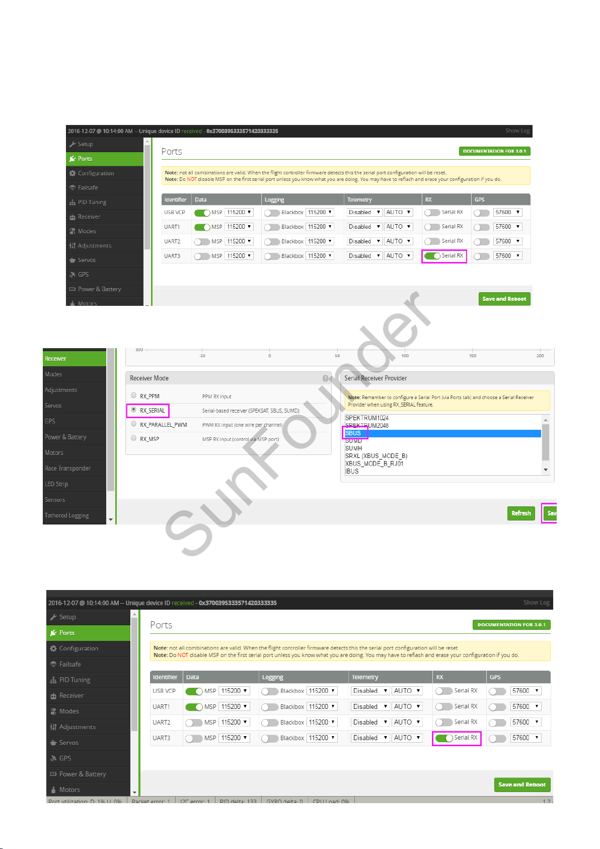
1) If your receiver is in the SBUS signal mode, click Ports on the left and enable Serial RX in UART3,
then click Save and Reboot.
2) Next, click Receiver on the left, select RX_SERIAL as Receiver Mode, and select SBUS in Serial
Receiver Provider. Then click Save.
DSM/DSMX Signal Mode
If your receiver is in DSM/DSMX signal mode, click Ports on the left and enable Serial RX in UART3,
and then click Save and Reboot.
32
Page 35
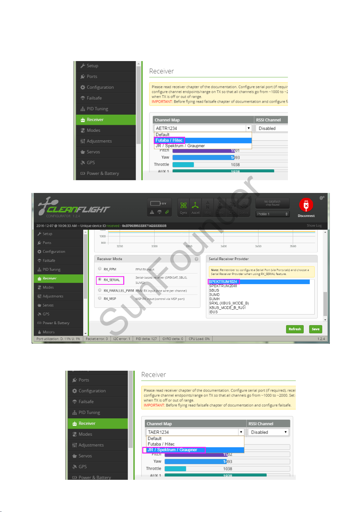
For DSM Signal Mode: Click Receiver on the left, select Futaba/Hitec for Channel Map. Select
SunFounder
RX_SERIAL as Receiver Mode, and select SPEKTRUM1024 in Serial Receiver Provider. Then click
Save.
For DSMX Signal Mode: Click Receiver on the left, select JR/ Spektrum / Graupner for Channel
Map, RX_SERIAL as Receiver Mode, and SPEKTRUM2048 in Serial Receiver Provider. Click Save.
33
Page 36
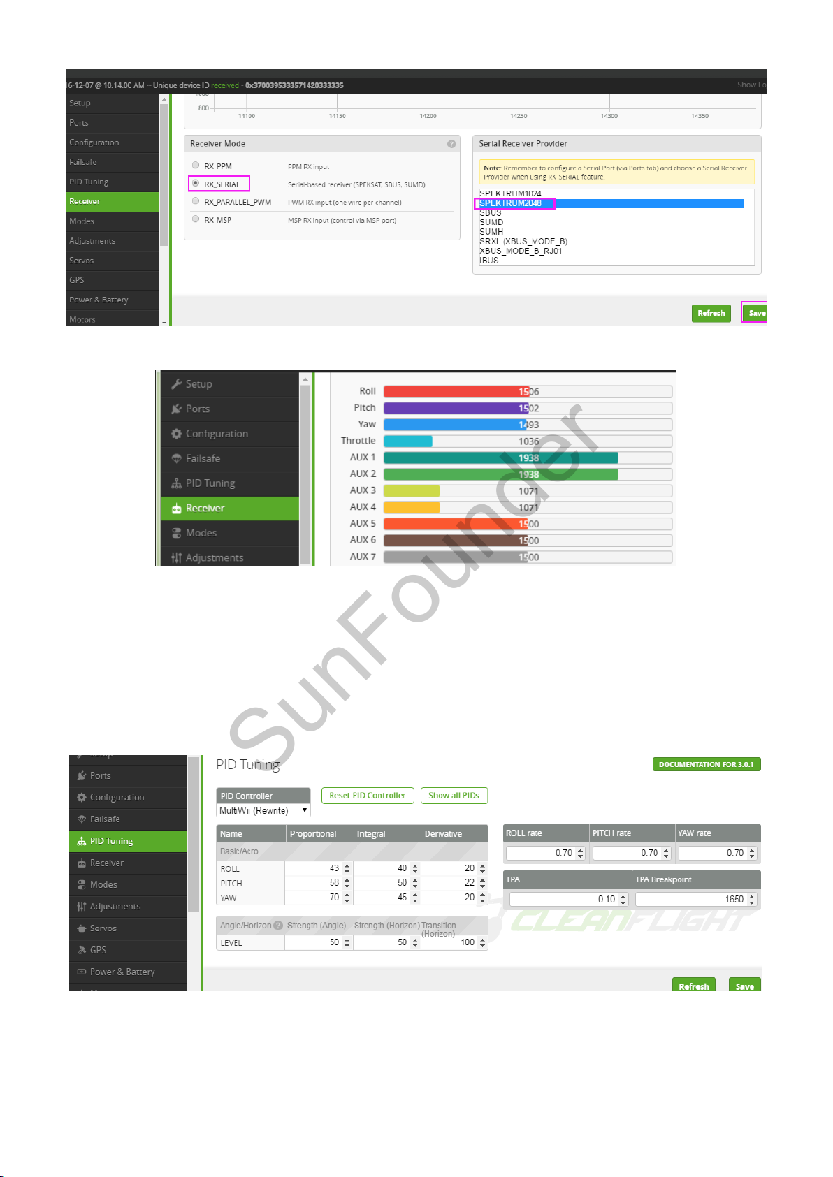
Now, you will see the corresponding figure changes when you pull the rocker of throttle or yaw.
SunFounder
3.3.4 Configuring Parameter of PID
Click PID Tuning, and you will see the PID value and RC rate of different channels. You do not
need to modify them. PID (Proportional Integral Derivative) is used to adjust the flight
performance. By default, the plane flies mildly, which will respond to the control a little slower.
You can adjust the PID parameters to get a more agile flight. If you are a beginner, you are not
recommended to do so.
34
Page 37
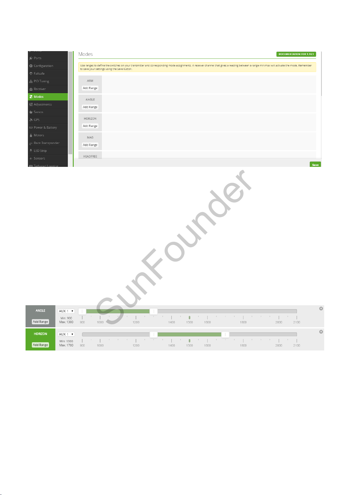
3.3.5 Configuring Flight Mode
SunFounder
Click Modes on the left to configure the flight mode.
1) Set self-stabilization mode, horizontal mode and manual mode.
You need to choose a 2-channel or 3-channel AUX x, set the self-stabilization mode, horizontal
mode, and manual mode to be controlled all by AUX x, and then configure the volume for three
modes in Cleanflight. For example, here we choose the 3-channel AUX1 to control these three
modes.
Click Add Range in ANGLE to run the self-stabilization mode. Select AUX1 and the value ranging
from 900 to 1300.
Click Add Range in HORIZON to run the horizontal mode. Select AUX1 and the value will be 1300
to 1700.
Then the rest is the value range of the manual mode. You can set the ranges for different modes
yourself. ANGLE (in green) indicates AUX1 is in ANGLE mode now. Try to slide the AUX1 switch, and
see whether the range changes or not.
Remember to click Save after any modification. If you don’t have a 3-channel AUX x, you can
choose two modes from the three.
35
Page 38
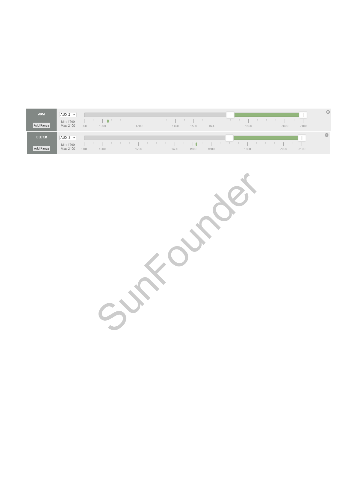
2) Set ARM/DISARM mode and alarm mode
SunFounder
Choose AUX x to control the ARM/DISARM mode of the aircraft. For example, here we choose
AUX2.
Click Add Range in ARM to set ARM/DISARM modes, and select AUX2 and the value ranging from
1700 to 2100.
Click Add Range in BEEPER to set the alarm mode, and select AUX3 and the value ranging from
1700 to 2100.
Click Save to save the settings.
After all the settings, click Disconnect at the top right of the software to break the connection
with the SF RACING F3.
36
Page 39
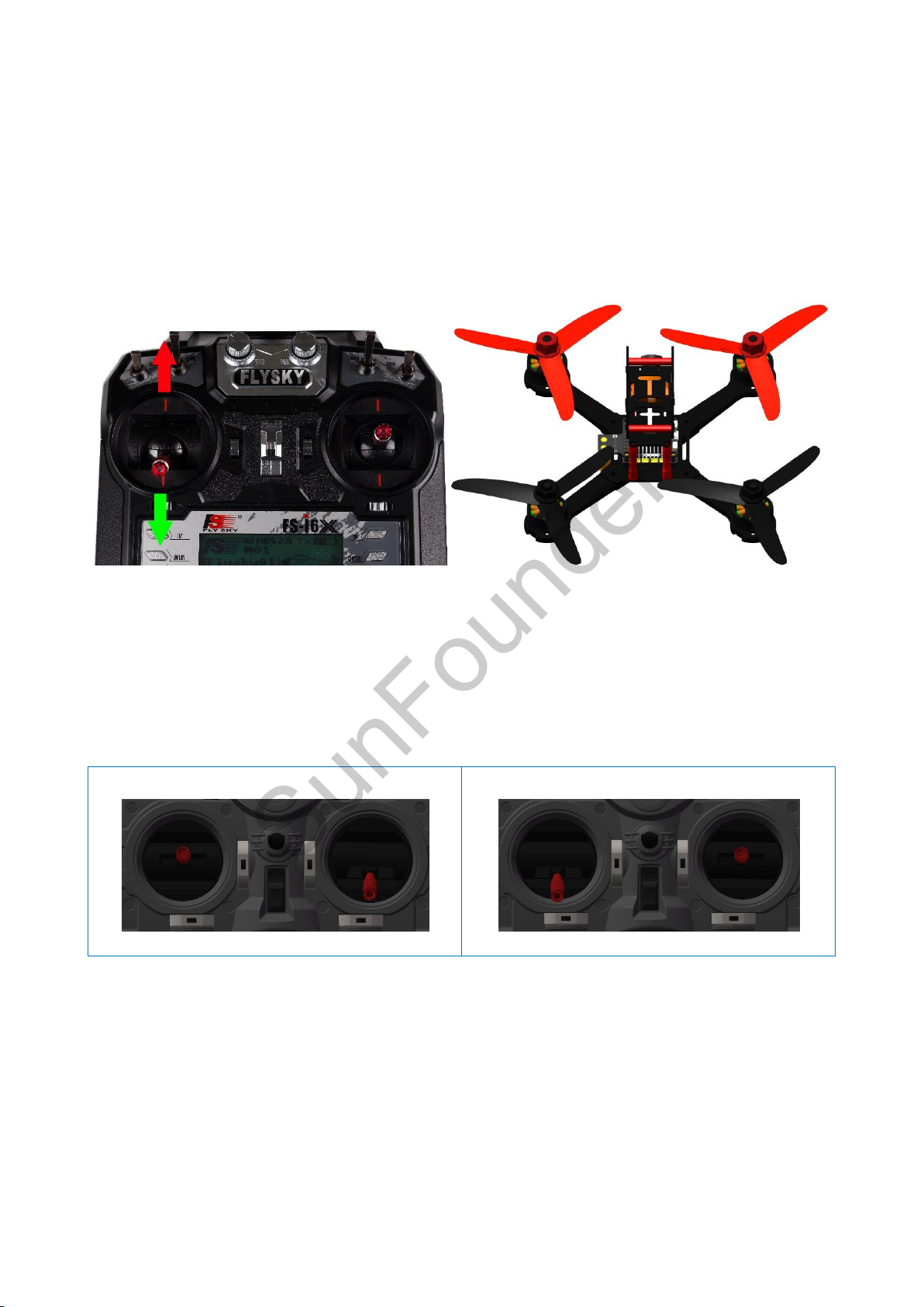
Appendix - Basics for Application
Remote Controller (right hand throttle)
Remote Controller (left hand throttle)
SunFounder
Unlocking the Aircraft
Place the aircraft on a level surface, or the RED LED will keep flickering - after it's done, the LED
will go out. Then pull the rocker of the throttle to the lowest, and toggle the AUX1 to self-
stabilization (recommended for beginners). Pull the AUX2 to the unlocked mode (ARM). The
aircraft is unlocked successfully if the RED LED on the flight controller lights up and keep on
constantly. Then you can pull the throttle gently to start flying the aircraft!
Control During the Flight
Before applying the remote control, you need to know there are two different types of remote
control. They are different in the position of throttle – left (what we provided in this kit) and right.
The throttle controls the motor speed. The higher you push it, the motor rotates faster, and the
quadcopter flies higher, and vice versa. It is quite easy to tell the throttle. Try to pull the two rocker
arms. The one that will not restore to the middle is the throttle rocker.
37
Page 40
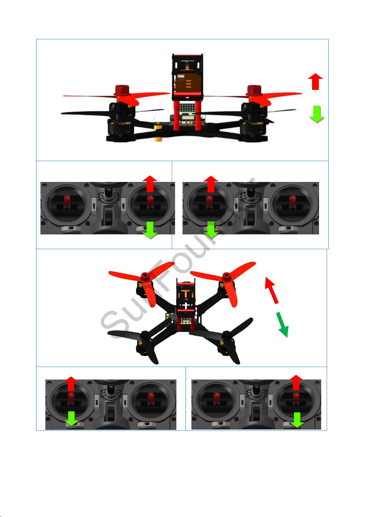
Basic Flight Modes and Corresponding Channels of Remote Controller
Aircraft (Climb -Sink)
Remote Controller (right hand throttle)
Remote Controller (left hand throttle)
Aircraft (Forward and backward)
Remote Controller (right hand throttle)
Remote Controller (left hand throttle)
SunFounder
38
Page 41
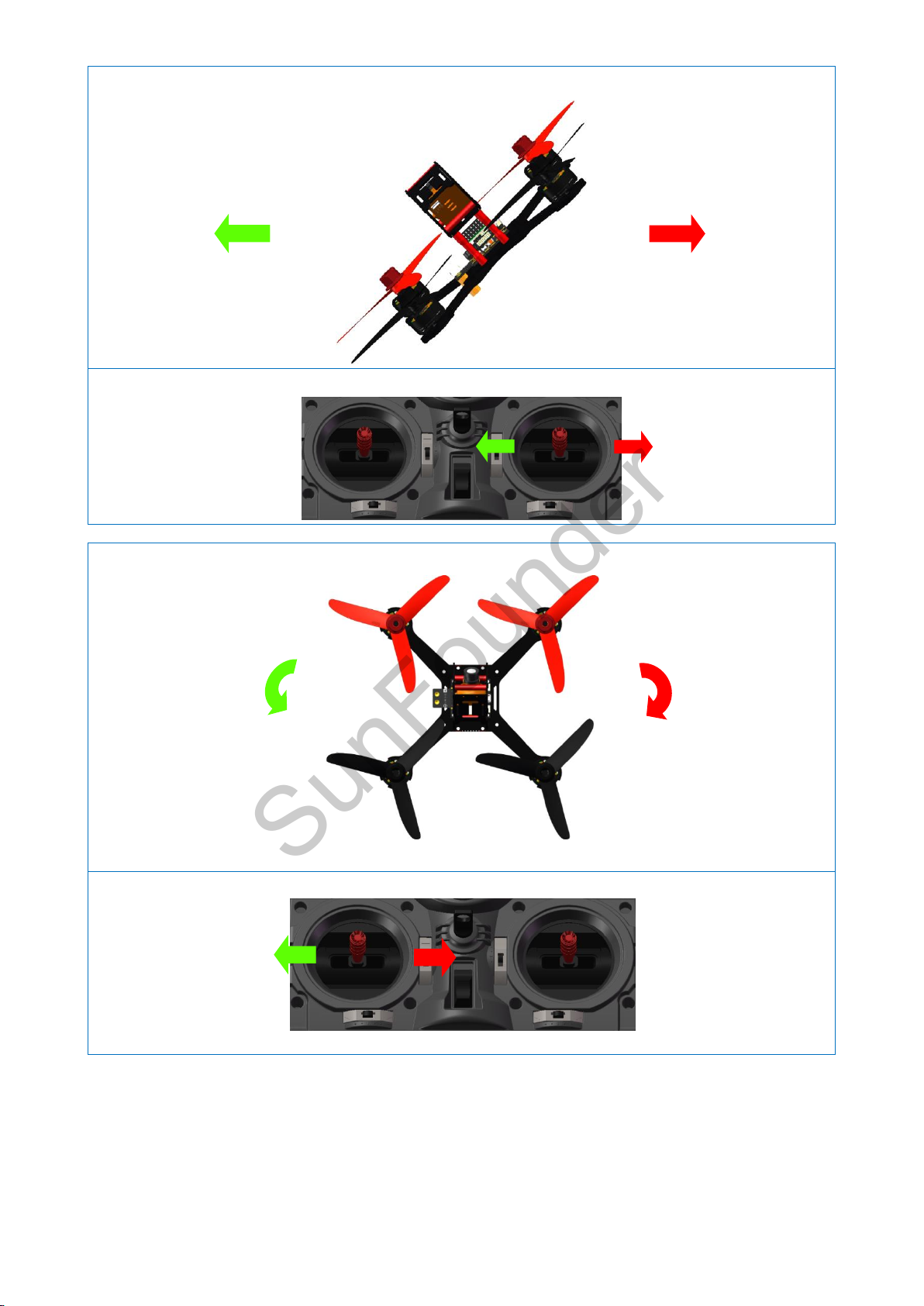
Aircraft (Roll to the right and left)
Remote Controller
Aircraft (turn on its own axis)
Remote Controller
SunFounder
39
Page 42

With the instructions above, you should now have completed all the tasks needed and be able
SunFounder
to fly the quadcopter. Enjoy the fun!
Remember if you have any tech questions, please feel free to post forums under FORUM on our
website www.sunfounder.com. We'll respond as soon as possible. Also welcome to share your
experience there.
Copyright Notice
All contents including but not limited to texts, images, and code in this manual are owned by the
SunFounder Company. You should only use it for personal study, investigation, enjoyment, or other
non-commercial or nonprofit purposes, under the related regulations and copyrights laws, without
infringing the legal rights of the author and relevant right holders. For any individual or organization
that uses these for commercial profit without permission, the Company reserves the right to take
legal action.
40
 Loading...