


SUNFAR E300 SERIES
Manual
E300 Series Mini-type Integrated
Universal Inverter Manual
1
SHENZHEN SUNFAR ELECTRIC TECHNOLOGIES CO.,LTD
E300 Series Mini-type Integrated Universal Inverter Manual

SUNFAR E300 SERIES
2
PREFACE
Thanks very much for choosing E300 series mini-type integrated universal inverter.
This manual provides guidance of using inverter safely and carefully, containing
introduction of installation, wiring, parameters list, routine maintenance, operating rules
and cautions, etc.
In order to make good use of inverter properly and safely, please read this manual
thoroughly before using. It may lead to abnormal operation or failure, reduce using life,
even damage equipment and cause personal injury if you it wrongly.
This manual is attachment together with the inverter. Please keep it well and it would be
available to engineering and installation personnel, repairing and maintaining during
product functioning period. SUNFAR has the right to modify and ameliorate products, data
and dimensions without notice, so this manual is updated and all the contents in this
manual are subject to change without any notice.
SHENZHEN SUNFAR ELECTRIC TECHNOLOGIES CO., Ltd.
E300 Series Mini-type Integrated Universal Inverter Manual
Version: v1.0
Time: Feb. 2009
E300 Series Mini-type Integrated Universal Inverter Manual

SUNFAR E300 SERIES
CONTENT
3
1. INTRODUCTION……………………………………………………
1.1. Model Explanation…………………………………………
1.2. Inverter Model………………………………………………
1.3. Appearance………………………………………………
1.4. Specification Data…………………………………………
2. INSTALLATION……………………………………………………
2.1. Environmental Requirements ………………………………
2.2. Installation Dimension……………………………………
3. WIRING………………………………………………………………
3.1. Precautions……………………………………………………
7
7
7
7
8
10
10
10
12
12
3.2. Wiring of External Components……………………………
3.3. Basic Wiring………………………………………………
3.4. Wiring of Main Loop Terminal ………………………………
3.5. Wiring of Control Loop Terminal…………………………
3.6. Wiring of RS485 Interface and External Keyboard ………
4. PANEL OPERATION………………………………………………
4.1. Key Function Description……………………………………
4.2. Panel Operational Method……………………………………
4.3. State Monitor Parameter List………………………………
E300 Series Mini-type Integrated Universal Inverter Manual
12
13
14
14
15
17
17
18
18

SUNFAR E300 SERIES
4
4.4. Inverter Simple Operation……………………………………
5. PARAMETER LIST…………………………………………………
6. FAULT DIAGNOSIS AND COUNTERMEASURES……………
6.1. Protective Function and Countermeasures…………………
6.2. Fault Record Inquiry……………………………………………
6.3. Reset……………………………………………………………
AppendixⅠRS485 COMMUNICATION PROTOCOL……………
1.1. Summary………………………………………………………
1.2. BUS Structure and Protocol Description ……………………
1.3. Frame Format Description……………………………………
19
21
23
23
24
24
25
25
25
29
1.4. Example…………………………………………………………
Appendix Ⅱ MODBUS PROTOCOL ………………………………
1.1. Protocol Format Explanation………………………………
1.2. Example…………………………………………………………
Appendix Ⅲ BRAKING RESISTOR………………………………
32
36
36
39
41
E300 Series Mini-type Integrated Universal Inverter Manual
SUNFAR E300 SERIES
5
PRECAUTIONS
In order to use inverter properly and safely, please read this manual carefully before using.
You should follow the requirements of this manual to move, install, run, operate and repair
etc.
1. Opening
Please check any damage that may have occurred during transportation.Ⅰ
Please check whether the nameplate data of iⅡ nverter is in accordance with your
order, if anything wrong, please contact supplier immediately.
Our product is manufactured, packed and transported in the strict quality system. But in
case there is any error, please contact with our company or local agent, we will solve the
problem as quickly as possible.
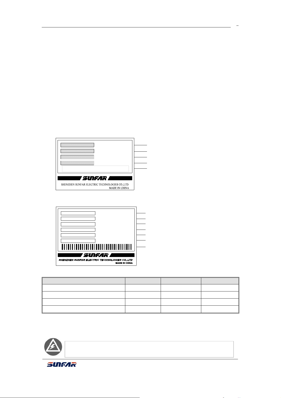
Inverter’s nameplate data
TYPE:
SOURCE:
OUTPUT:
SERIAL No.:
E300-2S0007
1PH 220V 50/60Hz
1.7KVA 4.5A
XXXXXXXXXX
Model
Rated Parameters
Rated output capacity and current
Product serial No.
Bar code
Fig-1 Nameplate
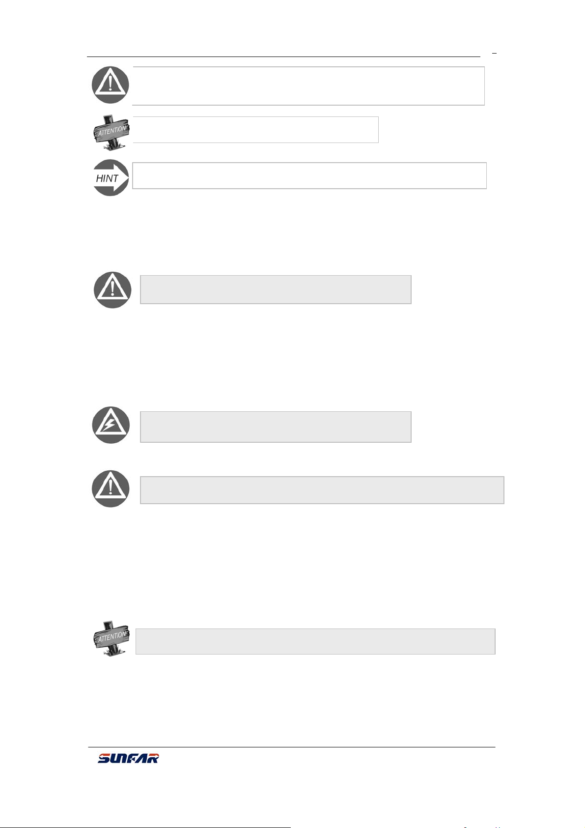
Package data
TYPE:
TYPE:
SOURCE:
SOURCE:
NET WEIGHT:
GROSS WEIGHT:
VOLUME:
SERIAL No.:
E300-2S0007
1PH 220V 50/60Hz
KG
KG
(mm)
XXXXXXXXXX
Model
Rated Parameters
Net Weight
Gross Weight
V
olume
Serial No.
Bar Code
Dimension
Model Net Weight Gross Weight Dimension
E300-2S0002/E300-2S0002(B) 0.78 0.97 195×115×175
E300-2S0004/E300-2S0004(B) 0.82 1.00 195×115×175
E300-2S0007/E300-2S0007(B) 1.43 1.66 203×135×180
E300-2S0015/E300-2S0015(B) 1.52 1.82 203×135×180
2. Safety Regulations
There are four kinds of symbols being related with cautions as following:
Danger: If user does not operate according to requirements, it will lead to
death, grievous bodily harm or severe property loss.
E300 Series Mini-type Integrated Universal Inverter Manual
6
p
1. D
B
t
i
ith filt
g
Warning: If user does not operate according to requirements, it will lead to
inverter injury or damage.
This symbol will hint some useful information.
This symbol will hint some items that need to be noticed in operation.
SUNFAR E300 SERIES
2.1 Installing
Do not install inverter on combustible material.
Do not install in the explosive ambient.
Do not drop other material into the inverter.
It is forbidden to disassemble and refit inverter.
2.2 Wiring
2.2.1. It must be operated by professional worker when wiring.
2.2.2. Please be sure to turn off the power supply at least 10 min before wiring.
2.2.3. Inverter and motor must be grounded correctly.
2.2.4. Be sure to wire and inspect after power-off at least10 minutes.
2.2.5. Electron components are sensitive about static electricity, so do not drop other
material in inverter or touch the main circuit.
It is forbidden to connect AC power supply with the U, V
and W out
ut terminals directly.
2.3 Maintenance
o not touch the radiator after power-off at least 10 minutes.
2. The earth terminal of inverter must be connected to ground reliably.
3. Attention Notes:
3.1. Be sure to install inverter in a well-ventilated ambient.
3.2. Motor temperature at inverter control will be higher than at main supply control,
which is normal phenomenon.
3.3. Ordinary motor cannot run at low speed for a long time, so user should select
special motor for inverter or reduce motor load under low speed.
3.4. When the altitude is over 1000m, inverter will be valid to decrease rated current,
and rated current will decrease 10% when attitude is increased 1500m.
e sure not to connec
other sur
e absorbers.
nverteroutput terminalsw
er capacitors and
4 Dispose:
When you dispose inverter and its parts, please pay attention to:
Capacitor: The capacitors in inverter may explode when they are burned.
Plastic: Poisonous gas may be generated when front panel is burned, please pay
attention to waste gas when plastic parts are burned.
Method: Please dispose inverter as industry rubbish.
E300 Series Mini-type Integrated Universal Inverter Manual
SUNFAR E300 SERIES
/
7
1 INTRODUCTION
1.1 Model Explanation
E300
Product
Mini-type
integrated
universal
inverter
Volt Class
4
2
380V
220V
Power Phase
T
S
3 PH
1 PH
1.2 Inverter Model
Rated Capacity
Model
E300- 4 T 0007 (B)
Rated Output
(KVA)
Current (A)
Derivative Model
Built-in braking
B
unit and RS485
communication
Applied Motor Power
(KW )
0002
0004
0007
0015
0.2
0.4
0.7
1.5
Applied Motor
Power (KW)
E300-2S0002 0.69 1.8 0.25
E300-2S0004 0.95 2.5 0.4
E300-2S0007 1.7 4.5 0.75
E300-2S0015 2.9 7.5 1.5
E300-4T0007 1.6 2.5 0.75
E300-4T0015 2.8 4.2 1.5
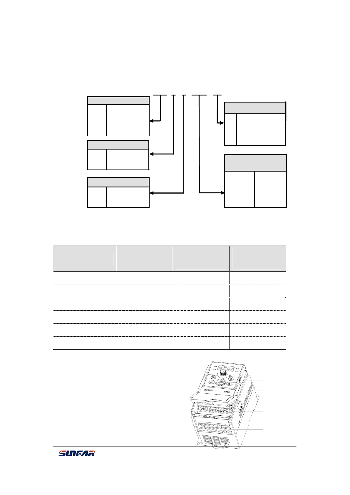
1.3 Appearance
1.3.1 Type One
Suitable model:E300-2S0002
E300
Fig 1-1 Type Ⅰ
E300-2S0004
Series Mini-type Integrated Universal Inverter Manual
Operation
panel
Cover
RS485
inte rfa c e
Control loop
cable input
M a in loop
cable input
Bo tto m
installation hole
Bo tto m side by-side button
SUNFAR E300 SERIES
A
8
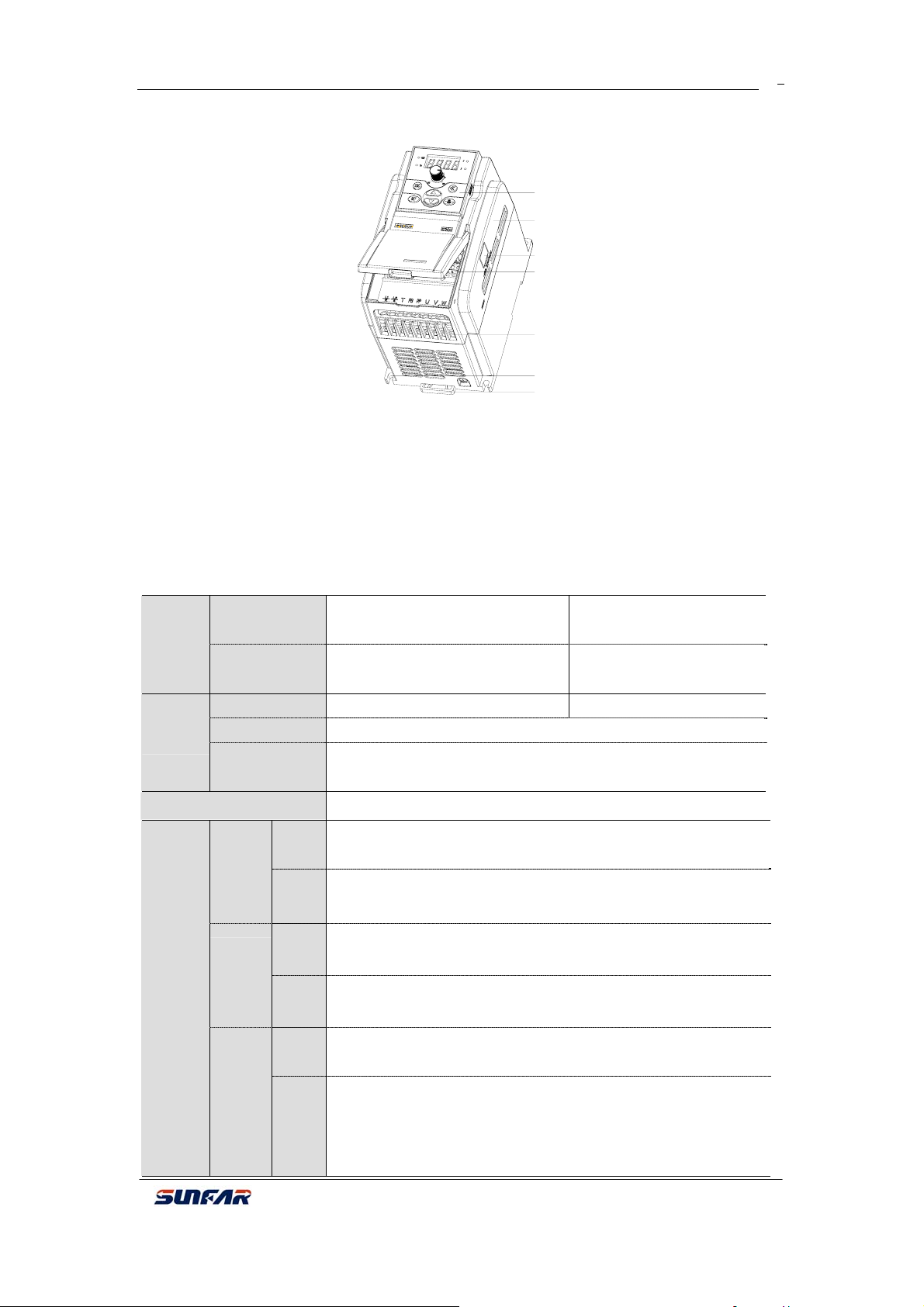
1.3.2 Type Two
Operation
panel
Cover
interface
RS485
Control loop
cable input
Main loop
cable input
Fig 1-2 TypeⅡ
1.4 Specification Data
E300 series power range:2S0002 ~2S0015 and 4T0007 ~4T0015。
E300 series specification data and typical function:
Rated volt and
Input
Permissible
volt range
Output
Overload
Endurance
Control Mode V/F control
Suitable model: E300-2S0007~
E300-2S0015/
3 PH(4T****)380V
freq
50/60 Hz
320V ~ 460V 170V ~ 270V
Volt 0 ~ 380V 0~220V
Freq 0~1000 Hz
110% for long-term;150% for 1m; 180% for 2s
Bottom
installation hole
Bottom side-byside buttome
1 PH(2S****)220V
50/60 Hz
on
Analog
Input
Digital
Input
Analog
Input
0.4% of maximum output freq
0.1 Hz
Within 0.4% of maximum output freq
Control
Freq
setting
Resoluti
Freq
Precisio
Characte
ristics
V/F
control
n
Digital
Input
Torque
boost
uto
current
/volt
Within 0.1% of setting freq
Manual set: 0.0~20.0% of rated output
It will check motor stator current and volt automatically based
on special arithmetic to control within allowable range to
ensure minimum failure during acc/ dec or stable running.
limit
E300 Series Mini-type Integrated Universal Inverter Manual
SUNFAR E300 SERIES
9
Multi-speed
control
RS485
communication
(E300B series)
Analog
Freq
setting
input
Digital
input
Seven programmable multi-speed control, three multi-speed
control terminal
Standard built-in RS485 interface, RS485 communication
protocol and MODBUS for choice
Panel potentiometer setting, DC volt 0~10V,DC current 0~
20mA
Operation panel setting,RS485 interface setting, UP/DW
terminal control
Relay
and
Typical
Function
Output
Signal
output
Analog
output
Acc /dec time
setting
One OC output and one relay output (TA, TB, TC) as many
OC
as 9 types of choice
One 0~10V volt signal
0.1~600s continuous setting, S curve and linear mode for
choice
DC braking Action freq 0~500.0 Hz, action time 0~20.0 S
Low noise
running
Running
function
Operati
Display
on
panel
display
Protection / warning
function
Runnin
g state
Warnin
Carrier wave freq 1.5 KHz ~ 12.0 KHz continuous
adjustments to ensure the lowest motor noise.
Upper and Lower freq setting, reversal operating restriction,
RS485 communication,, freq increasing/decreasing control
etc.
Output freq, current and volt,motor rotate speed,freq
setting, module temperature,analog I/O
Last four times failure record, output freq, current, volt and
g
DC volt of last fault trip for running parameter record
Over current,over volt, under volt, overheating, short circuit
etc.
E300 Series Mini-type Integrated Universal Inverter Manual
SUNFAR E300 SERIES
2 WIRING
2.1 Environmental Requirements:
10
¾ Ambient temperature should be in range of-10 ºC-40 ºC.
¾ Please avoid putting inverter in a high temperature and moist location.
The humidity is less than 90% and non-condensing.
¾ Avoid sunshine directly.
¾ Keep away from combustible, explosive material and caustic gas or
liquid.
¾ No dust, floating fiber and metal particles.
¾ It must be installed in a firm and no vibration location.
¾ Keep away from electromagnetic disturbance.
If users demand any special installation, please contract us firstly.
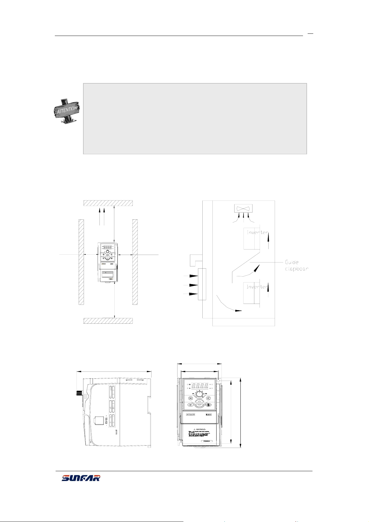
Installation space and distance of single inverter shows as fig 2-1-A that ambience should
be enough space. For several inverter installations, it should adopt guide clapboard to
ensure better cooling between each inverter shown as fig 2-1-B.
Above 50mm
Fan
ventilation
WARNING
!
1.Refer to the instruction manual before installation
and operation.
2.Do not connect AC power to output terminals UVW.
3.Do not remove any cover while applying power
and at least 10min. after disconnecting power.
4.Securely ground(earth) the equipment.
Above 120mm
Above 50mm
Above 120mm
Fig 2-1-A Installation space distance Fig 2-1-B Installation for several inverters
2.2 Installation Dimension
2.2.1 Dimension
Suitable model:E300-2S0002/ E300-2S0004 as fig
D
Fig 2-2-A Inverter installation
E300 Series Mini-type Integrated Universal Inverter Manual
W
W1
H1
H
SUNFAR E300 SERIES
Suitable model:E300-2S0007~2S0015/ E300-4T0007~4T00015 as fig 2-2-B.
D
Fig 2-2-B Inverter installation
E300 series installation dimension:
Model
Model
W1 W H1 H D
(3PH 380V)
(1PH 220V)
W
W1
H
H1
11
Screw
spec
E300-2S0002
67.5 81.5 132.5 148 134.5 M4
E300-2S0004
E300-4T0007 E300-2S0007
86.5 101.5 147.5 165 154.5 M4
E300-4T0015 E300-2S0015
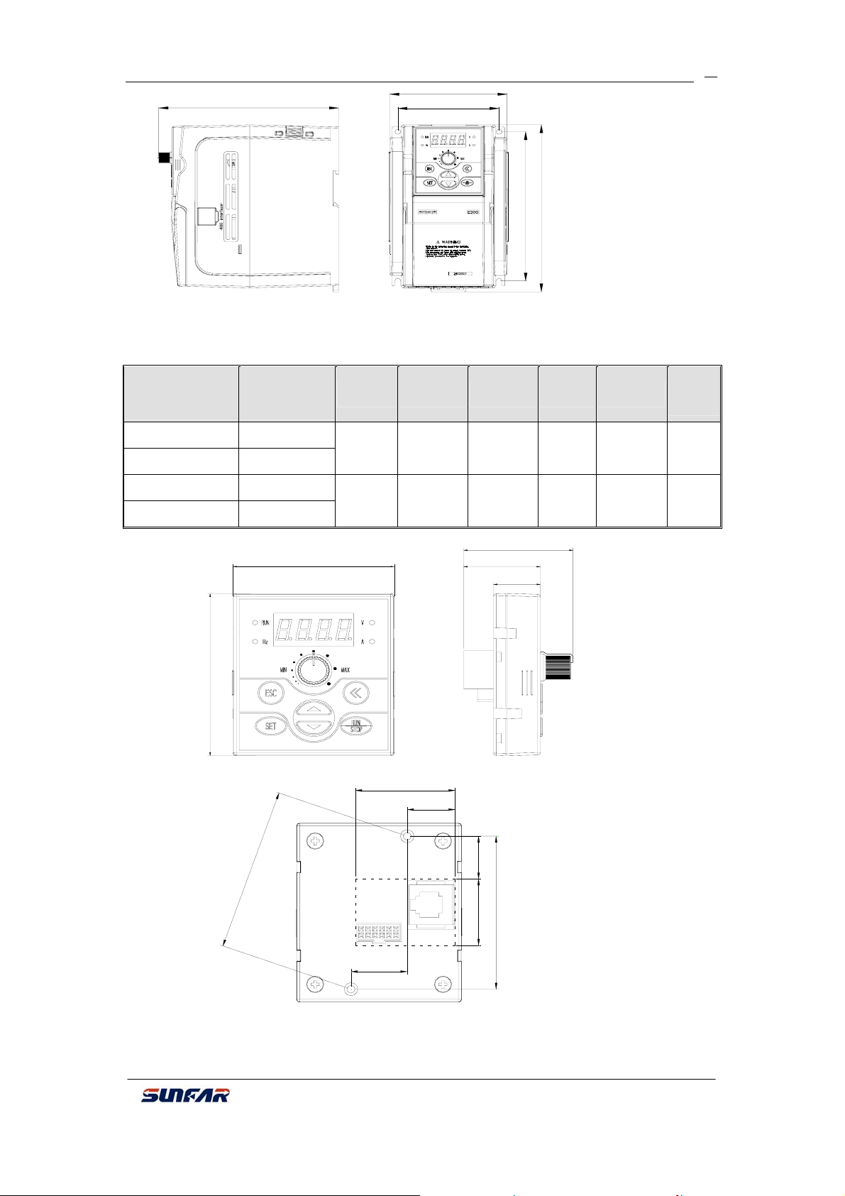
2.2.2 Options Installation Size
68.7
2
.
2
6
Fig 2-2-D Small keypad base installation size
60.7
Fig 2-2-C Small keypad installation size
36.7
17.6
20.7
41.1
28.8
17.6
16.425.5
58.7
Note: When using screw M3, please pay attention to hole place in broken line and hole
size.
E300 Series Mini-type Integrated Universal Inverter Manual

SUNFAR E300 SERIES
12
3 WIRING
3.1 Precautions
(1)Install a middle breaker between inverter and power supply avoiding enlarging
accident.
(2)For reducing electromagnetic interface (EMI), please connect surge absorber to
coil of electromagnetic contactors, relays etc.
(3)Freq setting terminal AI, instrument circuit(AO)etc., these analog signals wire
should be over 0.3mm² shield wire. Shield layer is connected with ground terminal CM
less than 30m.
(4)Wiring of relay input and output loop (X1 ~ X3) should choose over 0.75mm²
intertwist or shield wire. Shield layer should be connected to control terminal CM less than
50m.
(5)Separate control wire from main loop wire, parallel wiring should be part over
10cm, and across wiring should be vertical.
(6)Wire of Inverter and motor should be less than 30m. When it is over 30m, it
should decrease inverter carrier wave freq properly.
(7)All down-lead should be tightened with terminals to ensure well-contact.
(8)Compressive resistance of all down-lead should match with inverter volt.
¾ Inverter output terminal U、V、W should not add absorber capacitor or other
RC absorber shown as fig.3-1.
Motor
M
Inverter
U
V
W
RC absorber
Fig 3-1 Output terminal does not allow connecting RC absorber
3.2 Wiring of External Components
AC pow er
Air-breaker switch
Contactor
AC re a c to r
Fig 3-2 Inverter wiring
E300 Series Mini-type Integrated Universal Inverter Manual
Braking resistor
PP PB
R/L1
S/L2
! WARNING
1.Refe r to th e in str u ct i on m a nu al b e fore inst alla ti o n
and operation.
2.Do not connect A C power to ou tput term inals UVW .
3.Do not rem ove any c over wh ile appl ying p owe r
T
and at least 10min. a fter disconn e cting pow er.
4.Securely ground(eart h) the equipm ent.
E300
U
V
W
Motor
SUNFAR E300 SERIES
A
M
T
T
T
A
r
A
g
13
Power
Please follow this manual for appointed input power specification.
Air-breaker switch
1. When inverter is in maintenance or long-time nonuse, air-breaker switch isolates
inverter and power supply.
2. When inverter input side has failure of short circuit or power low-volt, air-breaker
switch can take protection.
Contactor
Control power-on and power-off of inverter and load motor.
AC reactor
1. Increase power factor;
2. Reduce power network harmonic wave input from inverter;
3. Weaken imbalance effect on three phase power volt.
Breaking resistor
In the situation of regenerative braking, avoiding bringing volt too high.
Recommended specification for the devices as following:
Wire spec
(main circuit)
(mm2)
Air-breaker
(A)
Magnetic
contactor (A)
Model
pplied motor
(KW)
E300-2S0002 0.25 1.5 10 6
E300-2S0004 0.4 1.5 16 6
E300-2S0007 0.75 2.5 20 12
E300-2S0015 1.5 2.5 32 18
E300-4T0007 0.75 1.0 10 6
E300-4T0015 1.5 1.5 16 12
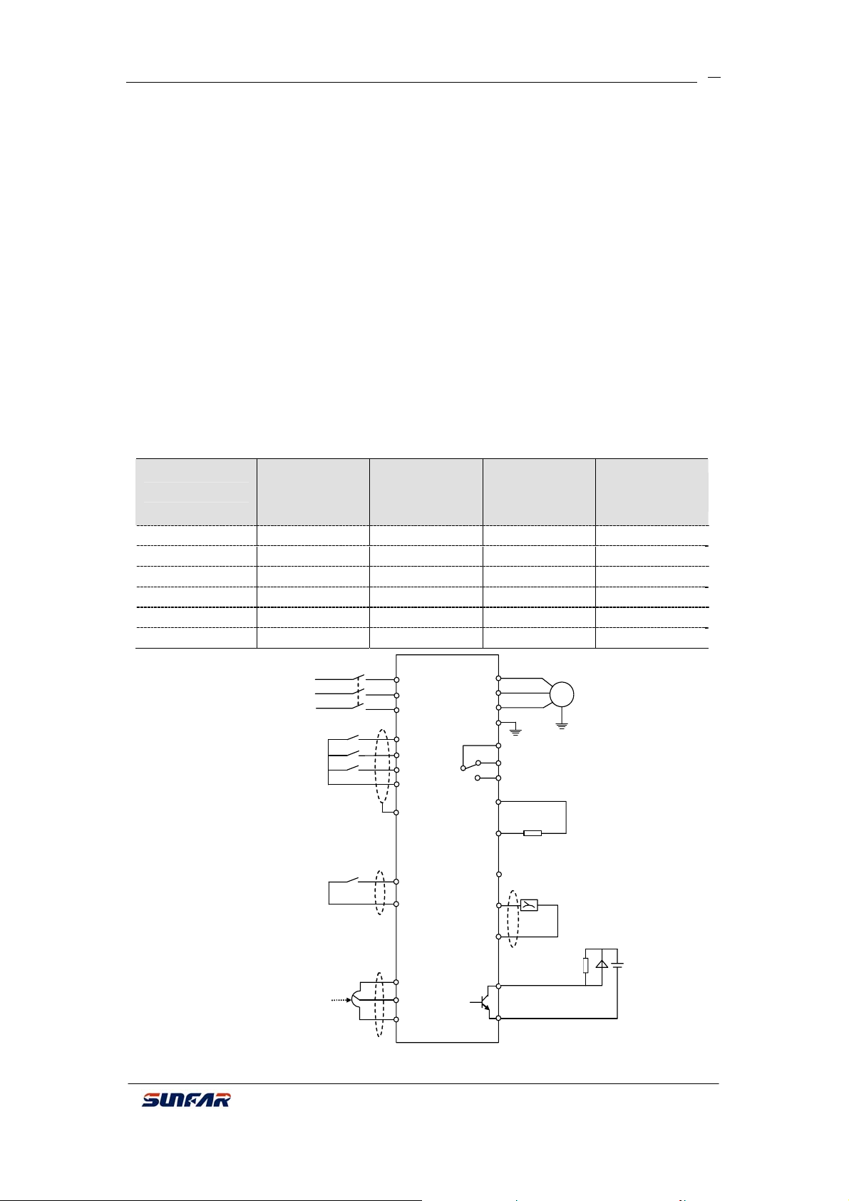
3.3 Basic Wiring
3PH power
supply
Programmable
input terminal
0~10V(0~20mA)
Freq setting
3PH breaker
×
×
×
FWD
R
S
T
X1
X2
X3
CM
E
FWD
CM
10V
I
CM
U
V
W
E
a
b
Failure alarm output
c
PP
PB
24V Auxiliary DC power
O
CM
Open-circuit
collector output
OC
CM
Motor
~
GND
External brakin
resistor
Vol tmet e
(0~10V)
Fig 3-3 Inverter basic wiring
E300 Series Mini-type Integrated Universal Inverter Manual

SUNFAR E300 SERIES
A
A
A
3.4 Wiring of Main Loop Terminal
(1) TypeⅠ(Suitable model: E300-4T0007~E300-4T0015)
Terminal description:
R S T PB PP U V W E
3PH power input
Braking resistor
Motor
Terminal Function Terminal Function
14
GND
Braking resistor can be
connected between PP
and PB.
Connect 3PH AC 380V
motor
PP
R、S、T
Positive terminal of
DC negative
Connect 3PH AC
380V power supply
PB
U、V、W
E GND
(2)Type Ⅱ(Suitable model: E300-2S0002~E300-2S0015)
:
L1
C 220V power
supply input
L2
PB
PP U EW
Braking
resistor
V
Motor
GND
Terminal description:
Terminal Function Terminal Function
Braking resistor can be
connected between PP and
PB.
PP
Positive terminal of DC
negative
PB
L1、L2
Connect 1PH AC 220V power
supply
U、V、
W
Connect 3PH AC 220V
motor
E GND
3.5 Wiring of Control Loop Terminal
(1)Control loop terminal:
TC
X1
X3 CM
OC
FWDTA TB
I10V
E300 Series Mini-type Integrated Universal Inverter Manual
24V
O X2

SUNFAR E300 SERIES
(2)Function description of control loop terminal:
Type Terminal Function Note
Provide +10V(0~20mA)
power
Provide +24V(0~50mA)
power(CM terminal as
this power grounding)
Volt(current)signal input
terminal
Public terminal of input
(output)signal(10V
and 24V power
grounding)
Multi-function input
terminal 1
Multi-function input
terminal 2
Multi-function input
terminal 3
FWD order input
terminal
Programmable volt
signal output terminal
and external voltmeter
(set by [F1.4])
Programmable
open-circuit collector
output set by [F1.11]
Normal TA-TB close and
TA-TC open appointed
function is valid; TA-TB
open and TA-TC close.
Parameter [F1.12]
selects output function.
Power supply
Analog input
Control terminal
Analog output AO
OC
output
Programmable output
10V
24V
AI
CM
X1
X2
X3
FWD
OC
TA
TB
TC
15
0~10V(0~20mA)
Specific function for
multi-function input
terminals, please
refer to parameter
[F1.7] ~ [F1.9] for
setting. Terminal
and CM terminal
close that is valid.
FWD-CM decides
running direction
when panel control
mode. It’s valid when
close with CM
terminal.
Volt signal output 0~
10V
Max load current
150mA, max
endurable volt 24V
Contactor capacity:
AC 250V, 1A resistive
load.
3.6 Wiring of RS485 Interface and External Keyboard
(1)Wiring mode of RS485 interface:
(2)RS485 interface adopts 8P“ crystal pin”
phone line and external keyboard interface
adopts 8P“crystal pin” net line.
Suitable model:E300-2S0002~E300-2S0015/E300-4T0007/E300-4T0015
E300 Series Mini-type Integrated Universal Inverter Manual
-(B)
+(A)

Ext
Ext
ernal keyboard interface
!
WARNING
1.Refer to the instruction manual before installation
and operation.
2.Do not connect AC power to output terminals UVW.
3.Do not remove any cover while applying power
and at least 10min. after disconnecting power.
4.Securely ground (earth) the equipment.
¾ E300B series has communication function. For this using, please refer to
appendix explanation.
¾ When inverter failure, RUN/STOP light on cover will display.
SUNFAR E300 SERIES
RS485 interface
Fig 3-4-A Wiring mode Ⅰ
ernal keyboard interface
Fig 3-4-B Wiring mode Ⅱ
16
E300 Series Mini-type Integrated Universal Inverter Manual

SUNFAR E300 SERIES
i
4 PANEL OPERATION
17
Running indicate light
LED display
RUN
Hz
V
A
Return
Up
Set
MIN MAX
ESC
SET
RUN
STOP
LED display data un
sec
%
rmp
Panel potentiometer
Switch
Run, stop, reset
Down
Fig 4-1 Operation panel layout
Note:E300 series keyboard interface can not be compatible with other Sunfar series keyboard. Please do
not use confusedly.
4.1 Key Function Description
Key Function
LED display Display inverter current running state parameter and set parameter.
A、Hz、V
RUN
Data modification key for modifying function code or parameter.
Return key. During normal monitor mode, press this key and enter
ESC
SET
Run and stop order key. When order channel chooses panel control
RUN
STOP
Switch key. During any state for modifying data by data, press this key
Panel potentiometer. When inverter running freq is set by potentiometer
MAXMIN
Corresponding unit of main LED display data
Operation indicator light means there is output volt from output terminal
U, V, W during inverter running.
During monitor mode, if freq order channel is digital set mode [F0.0]=0),
press this key directly to modify freq setting value.
non-normal monitor mode/ monitor parameter check mode which can
check inverter running state parameter. During any operation state,
only press this key that can return to last state.
Set key ensures current state or parameter(parameter stores in inner
storage)and enters next function menu.
[F0.2] =###0), this key is valid. It is trigger key. During inverter stop
state, press this key and start inverter running. During inverter running
state, press this key to input stop order for running. During inverter
failure state, this key as failure reset key.
to choose modified data which may display.
(F0.0=3), you may decrease and increase running freq by rotating
potentiometer knob.
E300 Series Mini-type Integrated Universal Inverter Manual

SUNFAR E300 SERIES
N
4.2 Panel Operational Method
(1)State parameter check (eg.)
Return
to
normal
control
ormal monitorDisplay:45.0 Output freq
control
State parameter
check
ESC
State parameter
check
Display:d.0 Monitor code
Display: d.2 Function code
ESC
Parameter check Di sp la y:383 Output volt
Enter p aram eter mo dify
mode (refer to next chapter)
Parameter check
mod e
Display:F0.0 Function code
(2)Parameter check and modify (eg.)
Normal
monitor mode
Display: 45.0 Output freq
Parameter
check
Display:F0.0 F u nction co de
Modify
parameter for
requirement
tore modified
parameter
ESC
Parameter
check
ESC
Parameter
check
Parameter
modify
SET
Parameter
store
Display:F0.1 Function code
Display:45.0 Parameter data
Display:50.0 Parameter data
Display: F 0.1 Function code
4.3 State Monitor Parameter List
SET
18
ESC
Select checked
state parameter
Confirm checked
SET
state parameter
ESC
SET
Select checked/
modified parameter
SET
ESC
ESC
C
o
n
t
i
n
u
e
m
G
i
v
e
u
p
m
o
d
i
f
i
c
a
t
i
o
n
o
d
i
f
y
o
r
r
e
t
u
r
n
Monitor code Content Unit
E300 Series Mini-type Integrated Universal Inverter Manual

SUNFAR E300 SERIES
M
19
d-0 Inverter current output freq Hz
d-1
d-2
Inverter current output current(virtual value)
Inverter current output volt(virtual value)
A
V
d-3 Motor rotate speed rpm
d-4 Inverter inner DC volt V
d-5
Inverter input AC volt(virtual value)
V
d-6 Set freq Hz
d-7 Analog input AI V
d-8 Running linear speed
d-9 Set linear speed
d-10 Input terminal state
d-11 Module temperature ºC
d-12 Analog output AO V
d-13 Reserved
d-14 1st failure record
d-15 2nd failure record
d-16 3rd failure record
d-17 4th failure record
d-18 Output freq of last failure Hz
d-19 Output current of last failure A
d-20 Output volt of last failure V
d-21 DC volt of last failure V
4.4 Inverter Simple Operation
4.4.1 Inverter initialization set
(1)Freq input channel selection([F0.0])
Inverter initialization set is different based on each model. Set this parameter as 0, inverter
freq is set by panel number.
(2)Operation input channel selection([F0.2])
Inverter initialization set is different based on each model. Set this parameter as [F0.2]
=###0, inverter stop and startup is controlled by the key of operation panel
4.4.2 Simple Operation
Forbid connect power supply to inverter output terminals U/V/W.
PH power
upply
3PH breaker
×
×
×
R
S
T
U
V
W
E
Motor
GND
Fig 4-2 Wiring of simple running
RUN
STOP
E300 Series Mini-type Integrated Universal Inverter Manual

SUNFAR E300 SERIES
20
① Please wire as fig 4-2;
② Be sure correct wiring then power on. Inverter displays “P.oFF”, then “0”;
Be sure [F0.0] = 0③ ;
④ Based on inverter nameplate data for applied motor, please set parameter [F0.12] and
[F0.13];
⑤ Press key to start inverter, and inverter outputs freq 0 and displays “0.0”;
RUN
STOP
⑥ Press key for UP function to increase set freq. Inverter output freq increases and
motor rotate speed increases;
⑦ Check motor running is normal or not. If any abnormal, please stop running immediately
and power-off. Then, check the reasons and run again;
Press key for DOWN function to decrease set freq⑧ ;
⑨ Press key again to stop running and power-off.
Manufacture setting value of carrier wave freq is fixed between 1.5-12KHz. If
motor without load and under high carrier wave freq running, it may cause
slight shock. So, please decrease carrier wave freq value (parameter [F0.8]).
RUN
STOP
E300 Series Mini-type Integrated Universal Inverter Manual

SUNFAR E300 SERIES
r
A
A
A
5. PARAMETER LIST
Function Code Name Setting range
0: Digital setting
Freq input channel / mode
F0. 0
selection
F0. 1 Freq digital setting 0.00 ~ upper freq 0.1
Operation channel and mode
F0. 2
selection
F0. 3 Lower freq 0.0 Hz ~ [F0.4] 0.1
F0.4 Upper freq [F0.3] ~ 1000 Hz 0.1
F0.5 Acc time 0.1 ~ 600.0 S 0.1
F0.6 Dec time 0.1 ~ 600.0 S
F0.7 Acc/ dec characteristics paramete
Basic operation parameter unit
F0.8 Carrier wave freq 1.5 ~ 12.0 Khz
F0. 9 Modulate mode 0: Asynchronism 1: Synchronization
F0. 10 Parameter read-in protection
F0. 11 Torque boost
F0. 12 Basic running freq 5.0 Hz ~ upper freq 0.1 50.0
F0. 13 Max output volt 25 ~ 250V, 50 ~500V 1 220, 440
I input lower volt
F1. 0
F1. 1 AI input upper volt
F1. 2 Min setting freq
F1. 3 Max setting freq
F1. 4 Analog output selection 0: Output freq 1: Output current 2: Output volt
O output lower limit 0.0V ~ [F1.6]
F1. 5
O output upper limit [F1.5] ~ 10.0V
F1. 6
Function selection of input terminal
F1. 7
1 (0 ~ 12)
Function selection of input terminal
F1. 8
2 (0 ~ 12)
Function selection of input terminal
F1. 9
I/O Parameter Unit
3 (0 ~ 12)
Reserved
F1. 10
Output terminal OC function
F1. 11
selection
Relay output TA/TB/TC function
F1. 12
selection
1: External input signal (0~10V / 0~20mA)
2: Serial communication terminal (1)
3: Panel potentiometer
4: External terminal selection
1st part of LED:Operation channel selection
0:Control by keypad
1:Control by external terminal
2: Serial communication terminal (1)
2nd part of LED:Operation mode selection
0:Two-line mode 1
1:Two-line mode 2
2:Three-line mode
3rd part of LED:Reversal avoidance
0: Invalid 1: Valid
4th part of LED: Self-startup when power-on
0: Prohibit 1: Allow
0: Linear acc/ dec
1: S curve acc/ dec
1: Only allow to modify parameter F0.1 and this
parameter
2: Only allow to modify this parameter
Other data: all parameter can be allow to modify
0.0 ~ 20.0 (%)
0.0V ~ [F1.1]
[F1.0] ~ 10.0V
0.0 Hz ~ [F1.3]
[F1.2] ~ 1000 Hz
0: Control terminal idle
1: Multi-speed control 1
2: Multi-speed control 2
3: Multi-speed control 3
4: FWD jog control
5: REV jog control
6: Freq setting channel selection 1
7: Freq setting channel selection 2
8: Free stop control
9: Three-line mode running control
10: DC braking control
11: REV control
12: Failure reset
0: During inverter running
1: Freq reach
2: Freq level check (FDT)
3: Overload check out
4: Freq reaches upper limit
5: Freq reaches lower limit
6: During zero speed running
7: Low-volt stop
8: Inverter failure
21
Minimum
Manufacture
Unit
1
1
0.1
1
0.1
1
1 0
0.1 6.0
0.1
0.1 10.0
0.1 0.0
0.1 50.0
1
0.1 0.0
0.1 10.0
1 11
1 1
1 2 ×
1 0
1 8
Setting
3
0.0
1000
0.0
50.0
10.0
10.0
0
8.0
0
0.0
0
Modify
Limit
×
×
×
E300 Series Mini-type Integrated Universal Inverter Manual

SUNFAR E300 SERIES
F1.13 Freq reach check out amplitude 0.0~ 20 Hz 0.1 5.0
F1.14 FDT (freq level) set 0.0~1000 Hz 0.1 10.0
F1.15 FDT output delay time 0.0~ 20.0 S 0.1 2.0 ×
F1.16 Overload warning level 50~200(%) 1 110
F1.17 Overload warning delay time 0.0 ~ 20.0 S 0.1 2.0 ×
F2.0 Startup freq 0.0 ~ 50.0 Hz 0.1 1.0
F2.1 Startup freq lasting time 0.0 ~ 20.0 S 0.1 0.0 ×
F2.2 Stop mode 0: Dec stop 1: Free stop 1 0
F2.3 DC braking initial freq when stop 0.0 ~ 500.0 Hz 0.1 3.0
F2.4 DC braking action time when stop 0.0 ~ 20.0 S 0.1 0.0 ×
F2.5 DC braking action volt when stop 0 ~ 50 (%) 1 10
F2.6 FWD jog freq 0.0 Hz~ upper freq 0.1 10.0
F2.7 REV jog freq 0.0 Hz ~ upper freq 0.1 10.0
F2.8 Acc moment level 110 ~ 200 (%) 1 170
Auxiliary running parameter unit
F2.9 Motor overload protection coefficient50 ~ 110 (%) 1 100
Initial volt of dynamic braking
F2.10
(E300B series)
F3.0 Multi-speed freq 1
F3.1 Multi-speed freq 2
F3. 2 Multi-speed freq 3
F3. 3 Multi-speed freq 4
F3. 4 Multi-speed freq 5
F3. 5 Multi-speed freq 6
F3. 6 Multi-speed freq 7
F3. 7 Linear speed coefficient setting
F3. 8 Monitor parameter selection 0 ~ 21 1 0
Parameter check and modification
F3. 9
authority
F3. 10 Parameter initialization
F3. 11 Low-volt protection level
Multi-speed and senior running parameter unit
F3. 12 Over-volt limitation action level
F3. 13 Current limit amplitude level 150 ~ 250 (%) 1 200
F3. 14 Program version 1800 ~ 1899 1 1800
Communication setting (E300B
F4.0
series)
F4.1 Master address (E300B series) 0 ~ 30 1 1
F4.2 Master response delay 0 ~ 1000 ms 1 5
Communication auxiliary function
F4.3
setting
Communication overtime checkout
F4.4
Communication function parameter unit
time (E300B series)
F4.5 Linkage setting proportion 0.1 ~ 10.0 0.1 1.0
300 ~400V
600 ~ 800V
0.0 Hz ~ upper freq
0.0 Hz ~ upper freq
0.0 Hz ~ upper freq
0.0 Hz ~ upper freq
0.0 Hz ~ upper freq
0.0 Hz ~ upper freq
0.0 Hz ~ upper freq
0.01 ~ 10.00
0 ~ 9999 1 1700
0: No action
1: Standard initialization
2: Eliminate failure record
3: Complete initialization
180 ~ 230V
360 ~ 460V
350 ~ 400V
700 ~ 800V
st
part of LED: Baud rate selection
The 1
0: Reserved 1: 1200 bps 2: 2400 bps
3: 4800 bps 4: 9600 bps 5: 19200 bps
The 2nd part of LED: Data format selection
0: No check 1: Even check 2: Odd check
The 3rd part of LED: Protocol selection
0: RS485 protocol
1: MODBUS communication protocol
The 4th part of LED: Reserved
The 1st part of LED: Inverter master and slave set
0: This inverter as slave
1: This inverter as master
The 2ndpart of LED: Action selection if
communication failure
0: Stop 1: Keep state
The 3rd and 4th part of LED: Reserved
0.0 ~ 50.00 Hz 0.01 3.00
1
0.1 35.0
0.1 15.0
0.1 3.0
0.1 20.0
0.1 25.0
0.1 30.0
0.1 35.0
0.01 1.00
1 0 ×
1
1
1 0114
1 0010
370
740
200
400
380
760
22
F4.6 Reserved
E300 Series Mini-type Integrated Universal Inverter Manual

SUNFAR E300 SERIES
6 FAULT DIAGNOSIS AND COUNTERMEASURES
6.1 Protective Function and Countermeasures
Code Fault Probable Cause Solution
Fu.01
Fu.02
Fu.03
Fu.04
Fu.05
Fu.06
Fu.07
Fu.08
Over-current
during inverter
acc running
Over-current
during inverter
dec running
Over-current
during inverter
running or stop
Over-volt during
inverter add
ruuning
Over-volt during
inverter dec
running
Over-volt during
inverter running
Over-volt when
inverter stop
Low-volt during
inverter running
1. Acc time is short
2. Motor direct startup during
rotation
3. Set high for torque boost
4. Power supply volt is low
Dec time is short Increase dec time
1. Load occurs mutation
2. Power supply volt is low
1. Input volt is high
2. Power supply is switched
on-off frequently
1. Dec time is short
2. Input volt is abnormal
1. Power supply volt is
abnormal
2. It has energy feedback
load
Power supply volt is
abnormal
1. Power supply volt is
abnormal
2. It has heavy load startup
in power net
1. Prolong acc time
4. Start after motor stop
5. Decrease torque boost volt
6. Check power supply volt and
decrease power
1. Decrease load fluctuation
2. Check power supply volt
1. Check power supply volt
2. Decrease acc torque set
1. Prolong dec time
2. Check power supply volt
3. Install braking resistor or
select braking resistor again
1. Check power supply volt
2. Install braking unit, braking
resistor or select braking
resistor again
Check power supply volt
1. Check power supply volt
2. Power supply separately
23
Fu.09 Reserved
Fu.10 Reserved
Fu.11
Fu.12 Inverter overload
Fu.13 Motor overload
Fu.14
Inverter
disturbance
Inverter
over-heat
Wrong act due to
electromagnetism
disturbance
1.Heavy load
2.Acc time is short
3.Torque boost is high
4.Power supply volt is low
1.Heavy load
2.Acc time is short
3.Protection coefficient set is
low
4.Torque boost is high
1.Fan duct obstruct
2.Environment temperature
is high
3.Fan damaged
1. Reduce load or change for
2. Prolong acc time
3. Decrease torque boost volt
4. Check power supply volt
1. Reduce load
2. Prolong acc time
3. Increase motor overload
protection coefficient [F2.9]
4. Decrease torque boost
1.Clear fan duct or improve
ventilation condition
2. Improve ventilation condition
and decrease carrier wave freq
3.Change fan
Add absorb circuit to inverter
disturbance source
higher power range inverter
E300 Series Mini-type Integrated Universal Inverter Manual

SUNFAR E300 SERIES
r
24
Fu.15
-Fu.19
Fu.20
Fu.21
Fu.40
Reserved
Current check
wrong
Reserved
Inner data
memorizer
wrong
Current check equip or
circuit damaged
Control parameter read-in
wrong
1. Check socket line
2. Refer to manufacturer
Refer to manufacturer
6.2 Fault Record Inquiry
E300 series inverter records recent four times failure code and last inverter failure output
parameter in order to find out the reasons.
Please refer to keypad operation way to look for information.
Monitor Item Content Monitor Item Content
d-14 Record of 1st failure d-18 Output freq of last failure
d-15 Record of 2nd failure d-19 Output current of last failure
d-16 Record of 3rd failure d-20 Output volt of last failure
d-17 Record of 4th failure d-21 DC volt of last failure
6.3 Reset
When inverter failure, you may select below ways for resuming normal running:
Ⅰ:When display failure code, press key
Ⅱ:Close external multi-funciton terminal X? (failure reset) and CM, then cutoff.
Ⅲ:Send failure reset order through RS485 interface.
Ⅳ:Cut power off.
¾ Be sure to check failure reasons and exclude it before reset, which may
cause inverter permanent damage.
¾ If can not reset or failure again after reset, please find out reasons. If not, it
may damage inverter.
¾ When overload or ove
-heat protection, please prolong 5 minute to reset.
RU
STONP
E300 Series Mini-type Integrated Universal Inverter Manual

SUNFAR E300 SERIES
25
AppendixⅠ:RS485 COMMUNICATION PROTOCOL
1.1 Summary
E300 series derivative models, E300B series supports standard RS485 communication
interface through PC/PLC to reach centralized monitor(send operation order, set inverter
running parameter and read inverter running state) to meet special using requirement. This
protocol is design for above function.
1.1.1 Protocol Content
This serial communication protocol defines transmission information and use format and it
includes master-polling (or broadcasting) format, master coding method. Content includes
function code of action, transferring data and error check. Slave response is the same
structure, and it includes action confirmation, returning data and error check etc. If slave
causes any error while receiving information or cannot finish action by master, it will send
one fault signal to master as a response.
1.1.2 Using Application
1. Suitable product
The protocol is suitable for all Sunfar product series ranges inverter(C300 series, C320
series, E350 series, E380 series, E300 series etc.), which also can be suitable for
communication protocol of some other inverter brands.
2. Suitable mode
(1) Inverter connects to PC/PLC control net of “single master multi-slave” with RS485.
(2) Inverter connects to PC/PLC monitor background of “point to point” with RS485/
RS232 (transition interface).
1.2 BUS Structure and Protocol Description
1.2.1 BUS structure
1. Interface mode
RS485(RS232 for choice, but need level translator)
2. Transmission mode
Asynchronism serial and semiduplex transmission mode. At the same time, only master or
only slave can send data, and the other only can receive data. Data during serial
Asynchronism communication, it would send by a frame to a frame as form of message.
3. Topological mode
In single-master system, there are 32 sites at most, one as master site and 31 slave sites.
The setting range of slave address is 0~30, 31 (1FH) is broadcast communication address.
Slave address must be exclusive in the network. Point to point mode is a special
application as single master and multi-slaves topological mode, which is only one slave
condition.
1.2.2 Protocol description
RS485 communication protocol is a kind of serial master-slave communication protocol,
and only an equipment as master can build protocol in network (named as
“Inquire/Command”). Other equipments as slaves only can provide data to correspond
master “Inquire/Command” or corresponding action for master’s “Inquiry/Command”.
E300 Series Mini-type Integrated Universal Inverter Manual

SUNFAR E300 SERIES
26
Master is PC, industrial machine or programmable controller etc, and slave is inverter.
Master not only visits some slave, but also sends broadcast information to all slaves. For
single master “Inquiry/Command”, all slaves will return a signal as response; for broadcast
information provided by master, slave no need offer any feedback to master.
1.Data structure
Three kinds of data transmission for choice:
(1)1 bit start-bit, 8 bit data bits, 1 bit stop-bit and no check bit.
(2)1 bit start-bit, 8 bit data bits, 1 bit stop-bit and even check bit(manufacturing
setting).
(3)1 bit start-bit, 8 bit data bits, 1 bit stop-bit and odd check bit.
2.Baud rate
Five baud rate for choice: 1200bps, 2400 bps, 4800 bps, 9600 bps, 19200 bps
3.Communication mode
(1)Adopt master “poll”, slave “response” point to point communication.
(2)Use inverter keypad sets inverter serial interface communication parameter, including
local address, baud rate and data format.
Master set must be same as inverter baud rate and data format.
4.Communication rule
(1) There are at least 5-byte startup interval time between data frames, only the
message with stated startup internal time is valid.
(2) Mater waiting time and inverter longest corresponding time is 8-byte transmission
time. If longer time, judge as communication failure.
(3) If inverter does not receive any message after communication overtime checkout
time (function code: F4.4), judge as wire-break. Then, based on communication
auxiliary function setting (function code: F4.3), it decides slave running state. (If
receive any message during this time, it will control under it.)
1.2.3 Message structure
Length of each message is between 11~18 bytes(based on data format),Character type
can be ASC code and hex.Ⅱ
Data showing rule: hex, high number before and low number after. Shown as bellow:
(1)ASC code of data 3800HⅡ :
Data place
Data value(hex)
( 2 ) Hex of 3800H: (invalid place as“0”)
Data place
Data value(hex)
9 10 11 12
Set data Set data Set data Set data
33 38 30 30
9 10 11 12
Set
data
Set
data
Set
data
Set
data
00 00 38 00
1. Master command frame
E300 Series Mini-type Integrated Universal Inverter Manual

SUNFAR E300 SERIES
yp
sum
Slave
State
State
27
sequence
Definit
This communication protocol defines: 2AH (ASC code of character) and 5AH are Ⅱ
available. When header is 2AH, all data behind header is ASC code. When header is Ⅱ
5AH, all data behind header is hex code and invalid byte fill 0. Unaided headers of 2AH
and 5AH aren’t rightful header. There need waiting time above five bytes before sending
header.
Set range of inverter address:0~30,31(1FH)as broadcast communication address.
(3)Order type
Order type is during master sending data frame for defining action of this frame data.
Based on different order type, frame length is different shown as below:
0 1 2 3 4 5 6 7 8 9 10 11 12 13 14 15 16 17
Send
Slave
Slave
Header
Slave
ion
2.Slave corresponding frame
General data definition description for data frame
sequence
Send
efinition
(1)Header
(2)Slave addr.
addr.
0 1 2 3 4 5 6 7 8 9 10 11 12 13 14 15 16 17
Header
Data Operation
0 Read slave state and characteristics information
1 Read slave running parameter
2 Read function code parameter
t
e
Slave
Slave addr.
O n
Operation
peratio
Order
order
order
Order area Addr. area Data area Check area 0DH
feedbac
corresp
Slave
feedbac
Corresponding
area
Data type
Data addr.
Data addr.
Set data
Set data
Set data
Set data
R nninu
R nninu
R nninu
Data
Data
Data
Addr.
area
Data area Check area 0DH
R nunni
C k hec
C k hec
C k hec
C k hec
C k hec
C k hec
Check
Check
Tail
Tail
3
4 Send control order
5
6~F
(4)Operation order
Master gives control order to slave and it exists in all types of data frame (master sends
4th and 5th)shown as bellow:
Data Operation Data Operation
00H Invalid order 10H Set slave running freq
01H FWD running startup 11H
Modify inverter RAM area function code parameter, it will not
save if power-off (no storage)
Modify inverter EPROM area function code parameter, it will save
if power-off
Reserved
FWD running startup with running freq
set
E300 Series Mini-type Integrated Universal Inverter Manual

SUNFAR E300 SERIES
28
02H REV running startup 12H
REV running startup with running freq
set
03H Stop 13H Stop with running freq set
04H Slave FWD jog 14H FWD jog running with running freq set
05H Slave REV jog 15H REV jog running with running freq set
06H Jog running stop 16H Jog stop with running freq set
…
…
…
…
20H Slave failure reset 30H Reserved
21H Slave urgent stop 31H Reserved
(5)Slave correspond
Slave data correspond to master is for action feedback of master order frame. It exists in
all type data frame shown as below:
Data Definition Data Definition
Slave receives data for normal
0
operation
Slave running prohibit modifying
2
data
1
3
Receive data beyond range
Data modification prohibited by
password
Try to read, reserve or hide
4
parameter
5
Reserved
When adopt ASC code Ⅱ
Appointed parameter code or
6
invalid address(beyond limitation)
Invalid order type or operation
8
order
When slave corresponding byte data is “6~8”, frame length of corresponding
frame is 11 byte.
7
9~F
transmission data, it exists
invalid ASC code characterⅡ
Reserved
Frame format is shown as below:
correspo
Slave
nd
Definition
0 1 2 3 4 5 6 7 8 9 10
addr.
Slave
addr.
Slave
Header
Slave addr.
corres
pond
Slave
0 0
Order/ corresponding
area
sum
Check
sum
Check
sum
Check
sum
Check area 0DH
Check
Tail
(6)State feedback
Slave sends back slave basic running state to master, which exists in all type data frame.
(Slave feedback 4
th
and 5th)shown as below:
Data Operation Data Operation
00H
Slave DC volt does not
prepare well
10H Reserved
E300 Series Mini-type Integrated Universal Inverter Manual

SUNFAR E300 SERIES
Sl
01H Slave FWD running 11H FWD acc
02H Slave REV running 12H REV acc
03H Slave stop 13H Abrupt stop then startup
04H Slave FWD jog running 14H FWD dec
05H Slave REV jog running 15H REV dec
06H Reserved 16H Slave is during DC braking state
20H Slave is during failure state 21H Slave urgent stop
(7)Check sum
ASC code value (ASC code format) / hex data sum from slave address to set data/ ⅡⅡ
running data.
(8)Tail
Hex“0DH”,that’s ASC code of “CR”Ⅱ 的 ASCⅡ
When slave failure and state feedback data is“20H”, feedback data frame 7th and 8th
data(data addr.)as failure code.
29
1.3 Frame Format Description
1.3.1 Order type 0 ―Read slave state and characteristics information
Master sends frame length 14 byte, slave corresponding frame length 18 byte.
Note: Slave offer different feedback of character information because of different
When master sends header, tail or check sum of data frame abnormal, slave maybe
can not be normal correspond.
Master send
0 1 2 3 4 5 6 7 8 9 10 11 12 13
Header
addr.
Slave
addr.
Slave
0
Operatio
n order
Operatio
n order
type
Data
sum
Check
sum
Check
sum
Check
sum
Check
00
0 1 2 3 4 5 6 7 8 9 10 11 12 13 14 15 16 17
Slave addr.
ave
Header
Slave addr.
Slave
State
Data type
State
Character
Character
Character
Character
Character
Check sum
Character
Check sum
Check sum
data value of master sending frame.
Tail
Check sum
Tail
Data Type
(master send)
Character Information(slave correspond)
6 7 8 9 10 11 12
0
Read
slave
Volt class 0 Power Power Power Power
E300 Series Mini-type Integrated Universal Inverter Manual

SUNFAR E300 SERIES
yp
yp
p
data
30
model
info.
Read
1
slave
model
Reserved Reserved Reserved Reserved Reserved Reserved
info.
Read
2
slave
Reserved Reserved # # # #
version
Read
3
slave
operation
Master
control
Master
freq set
Reserved Reserved Reserved Reserved
info.
4~
Reserved # # # # # #
F
Eg. If master sending frame data value is zero, slave corresponding information is 400015.
It means: 4 as volt class, 380V;0 as charater information value;0015 as power, 1.5Kw.
1.3.2 Order type 1―――Read slave running parameter
Master sending frame length is 14 byte, and slave corresponding frame length is 18 bytes.
send
Header
addr.
Slave
addr.
Slave
1
order
on
Operati
order
on
Operati
0
C k
hec
sum
Check
Data
t
t
e
e
C k
Data
sum
hec
sum
0 1 2 3 4 5 6 7 8 9 10 11 12 13
Master
corres
ond
0 1 2 3 4 5 6 7 8 9 10 11 12 13 14 15 16 17
Slave
Header
Slave addr.
correspond
feedback
Slave
feedback
State
State
Data type
Data type
R ng
R ng unni
data
R ng
unni
unni
Check sum
Check sum
Running
Check sum
Slave addr.
0
Data type: For inverter monitor parameter item, E300 series monitor parameter item as
follow:
Monitor Item Data type Slave Feedback Value
d.0 00 Output freq
d.1 01 Output volt
...
d.15 15 The 2nd failure record
..
.
...
..
.
...
..
.
sum
Check
Check sum
Tail
Tail
d-21 21 The last failure DC current
Please refer to E300 series manual chapter four, 4.3 state monitor unit to check
inverter monitor parameter.
E300 Series Mini-type Integrated Universal Inverter Manual

SUNFAR E300 SERIES
M
t
Slave
eedbac
Ch
k
Slave
F
31
1.3.3 Order type 2―――Read function code parameter
Master sending frame length is 14 byte, and slave corresponding frame length is 18 byte.
0 1 2 3 4 5 6 7 8 9 10 11 12 13
Slave addr.
Slave
Slave addr.
correspon
Slave
order
2
f
State
k
Header
as
er
correspond
0 1 2 3 4 5 6 7 8 9 10 11 12 13 14 15 16 17
Slave
H eread
Please refer to order type 3 and 5 for data type and data addr.
Operation
State
order
Data type
Operation
Data addr.
Data type
Data addr.
Data addr.
Pa ter rame
Data addr.
Pa ter rame
Check sum
Pa ter rame
Check sum
Pa ter rame
Check sum
C k hec
Check sum
C k hec
Tail
C k hec
1.3.4 Order type 3―Modify RAM area function code parameter
1.3.5 Order type 5―Modify EPROM area function code parameter
Master sending frame length is 18 byte, and slave corresponding frame length is 18 byte.
Master send
0 1 2 3 4 5 6 7 8 9 10 11 12 13 14 15 16 17
Op on erati
Operation
Header
Slave
Slave
3
order
Data
or
5
Data type
Data
Set data
Set data
Set data
S ta et da
C k
hec
sum
C k
hec
Check
Tail
ec
Check
Tail
0 1 2 3 4 5 6 7 8 9 10 11 12 13 14 15 16 17
Slave
Header
Slave
correspon
Slave
State
State
Data type
Data addr.
Data addr.
Set data
Set data
Set data
S ta et da
C k
hec
C k hec
Data type definition:
Function
code unit
F1 F2 F3 F4 F5 F6 F7 F8 F9 FC FE FF FH FL FP
Data type 01 2 3 4 5 6 7 8 9 A B C D E F
Function code relative addr.: eg. Data addr. of F0.8、F1.8、F2.8、F#.8 is 8, but different data
type.
Note: When slave can not finish master order, feedback setting data is 0000.
1.3.6 Order type 4―――Send control order
Master sending frame length is 15 byte, and slave corresponding frame length is 18 byte.
For normal operation, this kind of frame is most suitable.
e
r
0 1 2 3 4 5 6 7 8 9 10 11 12 13 14
C k hec
Check
Tail
E300 Series Mini-type Integrated Universal Inverter Manual

C
p
Slave
r
sum
heck
C k
hec
32
SUNFAR E300 SERIES
Operatio
Operatio
Header
corres
ond
Set data of master sending frame is set freq from master sending to slave.
Running data of slave corresponding frame is master sending running parameter which
decides by set content from monitor item (function code: [F3.8]) in inverter function
parameter unit, meantime, slave feedback this item monitor value.
0 1 2 3 4 5 6 7 8 9 10 11 12 13 14 15 16 17
Slave
H er ead
Please refer to E300 series manual chapter five, function parameter unit, to check inverter
function parameter unit.
addr.
Slave
Slave
addr.
Slave
Slave
4
correspon
State
n order
n order
State
Set data
M or
onit
0
Set data
M or
onit
Set data
Set data
sum
R ng
R ng
unni
R ng
unni
unni
C
sum
heck
R ng
unni
C
sum
heck
C k
hec
Check
C k
hec
Tail
Check
Tail
1.4 Example
1.4.1 Read slave state and character information (order type 0)
Data set: read slave model.
Master
Explain Header Addr. 00 0 order No data type Adding hex Tail
Data return: model is 2S0004.
Slave
return
Digit 1 2 1 2 1 6 4 1
Explain Head
Header
send
Digit 1 2 1 2 1 2 4 1
2A 30 30 30 30 31 30 30 30 0D
Eg.
5A 00 00 00 00 01 00 00 00 0D
Head Slave State Data Character
er addr. feedback type information
2A 30 30 30 30 33 30 0D
Eg.
5A 00 00 00 00 03 00 0D
er
Slave Order Operation Data
addr. type order type
Running
startup
Slave
corresp Check sum Tai l
ond
0
slave
return
Slave
receive
data
Slave stop
state
No
data
type
Data type Check sum Ta i l
32 30 30 30 32
30 30 34 34 39
02 00 00 00 00
00 00 04 00 09
02-volt class 2S
04 - powe
0.4KW
Adding hex or
adding algorism
30 31
38 31
00 00
00 01
Ta il
E300 Series Mini-type Integrated Universal Inverter Manual

SUNFAR E300 SERIES
1.4.2 Read slave running parameter (order type 1)
Data set: read d-6(present set freq).
33
Master
send
Explain Header Addr. 00 1 order
Data return: return to present set freq 50.0 Hz.
Slave
return
Explain Header
Header
Digit 1 2 1 2 1 2 4 1
Eg.
Digit 1 2 1 2 1 2 4 4 1
Eg.
2A 30 30 31 30 30 30 30 36 30 31 38 37 0D
5A 00 00 01 00 00 00 00 06 00 00 00 07 0D
Header
2A 30 30 30 30 33 30 30 36
5A 00 00 00 00 03 00 00 06
Slave
addr.
Slave
addr.
0 slave
return
Order
type
Slave
correspond
Slave
receive
data
Operation
order
Invalid
order
State
feedback
Slave
stop[
Data type Data type Check sum Ta il
D
parameter
unit
Display
parameter
D
Parameter
unit
D
parameter
Data
type
No data
type
Adding hex Tail
Running
data
30 31
46 34
00 00
01 F4
Set freq
50.0 Hz
Adding
Check
sum
30 32
36 34
00 00
00 FE
hex
Ta il
0D
0D
Ta il
1.4.3 Read function code parameter (order type 2)
Data set: read parameter [F0.8]
Master
send
Explain Header Addr. 00 2 order
Data return: carrier wave freq [F0.8]=8.0KHz.
Slave
return
Header
Digit 1 2 1 2 1 2 4 1
2A 30 30 32 30 30 30 30 38
Eg.
5A 00 00 02 00 00 00 00 08
Header
Digit 1 2 1 2 1 2 4 4 1
2A 30 30 30 30 33 30 30 38
Eg.
5A 00 00 00 00 03 00 00 08
Slave
addr.
Slave
addr.
Order type
Slave
correspond
Operation
order
Invalid
control
order
State
feedback
Data type Data addr.
F
parameter
unit
Data type
Data
type
F
parameter
Return
data
30 30
35 30
00 00
00 50
Check
sum
30 31
38 41
00 00
00 0A
Adding
hex
Check
sum
30 32
35 30
00 00
00 5B
Ta il
0D
0D
Ta il
Ta il
0D
0D
E300 Series Mini-type Integrated Universal Inverter Manual

SUNFAR E300 SERIES
34
Explain Header
0 slave
return
Slave
receive
data
Slave
stop
state
F0
Parameter
unit
F0.8
Return
data as
8.0KHz
Adding
hex
Ta il
1.4.4 Modify RAM area function code parameter (order type 3)
Data set: modify data set freq [F0.1]=50.0Hz, not keep when stop.
Master
send
Digit 1 2 1 2 1 2 4 4 1
Explain Header
Data return: data correct set.
Slave
return
Explain Header
Header
2A 30 30 33 30 30 30 30 31
Eg.
5A 00 00 03 00 00 00 00 01
Header
Digit 1 2 1 2 1 2 4 4 1
Eg.
Slave
addr.
Addr.
Slave
2A 30 30 30 30 33 30 30 31
5A 00 00 00 00 03 00 00 01
0 slave
return
00
addr.
Order
3 order
Operation
type
Slave
correspond
Slave
receive
data
order
Invalid
control
order
feedback
Slave
Data type Data type Set data
F0
Parameter
unit
State
stop
state
Data type
Parameter
F0. 1
Parameter
Data
addr.
F0
F0.1
unit
30 31
46 34
00 00
01 F4
Set freq
50.0Hz
Set data
30 31
46 34
00 00
01 F4
Set data
50.0HZ
Check
sum
30 32
35 46
00 00
00 F9
Adding
hex
Check
sum
30 32
35 46
00 00
00 F9
Adding
hex
Ta il
0D
0D
Ta il
Ta il
0D
0D
Ta il
1.4.5 Send control order (order type 4)
Data return: set slave 0 inverter FWD running freq 10.0 Hz.
Master
send
Digit 1 2 1 2 4 4 1
Eg.
Explain Header Addr. 00 4 order
Data return: 0 inverter receives data normally.
Slave
return
Digit 1 2 1 2 1 2 4 4 1
Header Slave addr. Order type
2A 30 30 34 31 31
5A 00 00 04 00 11
Header
Slave
addr.
Slave
correspond
feedback
State
Operation
order
FWD with
freq set
0
Set data Check sum Tail
30 30
36 34
00 00
00 64
Set freq
10.0 Hz
Monitor
item
Running
30 31
43 30
00 00
00 79
Adding hex Tail
Check
data
sum
0D
0D
Ta il
E300 Series Mini-type Integrated Universal Inverter Manual

SUNFAR E300 SERIES
35
2A 30 30 30 30 31 30 30 30
Eg.
5A 00 00 00 00 01 00 00 00
Explain Header
0
slave
return
Slave
receive
data
Slave
FWD
running
Fixed
data
Present
display
monitor
d-0
30 30
36 34
00 00
00 64
Data set
successfully
30 32
34 42
00 00
00 65
Adding
hex
0D
0D
Ta il
1.4.6 Modify EEPROM parameter (order type 5)
Data send: modify torque boost [F0.11]=6.0, store when stop.
Master
send
Digit 1 2 1 2 1 2 4 4 1
Explain Header
Header
2A 30 30 35 30 31 30 30 41
Eg.
5A 00 00 05 00 01 00 00 0B
Slave
addr.
Addr.
Order
type
00 5 order
Operation
order
Slave
FWD
running
Data type Data type
F0
Parameter
unit
F0.11
Parameter
Set
data
30 30
33 43
00 00
00 3C
Data
set
Check
sum
30 32
36 44
00 00
00 4D
Adding
hex
Tail
0D
0D
Tail
Data return: slave receives data normally.
Slave
return
Explain Header
Header
Digit 1 2 1 2 1 2 4 4 1
Eg.
Slave
addr.
2A 30 30 30 30 31 30 30 41
5A 00 00 00 00 01 00 00 0B
0 slave
return
Slave
correspond
Slave
receive
data
State
feedback
Slave
FWD
running
Data type
F0
Parameter
unit
Data
addr.
F0.11
Set data
30 30
33 43
00 00
00 3C
Data set
successfully
Check
sum
30 32
36 38
00 00
00 48
Adding
hex
Ta il
0D
0D
Ta il
E300 Series Mini-type Integrated Universal Inverter Manual

SUNFAR E300 SERIES
r
36
AppendixⅡ:MODBUS PROTOCOL
1. Communication Set
F4.0=X1XX, choose MODBUS RTU protocol;
F4.0=X0XX, choose RS485 protocol.
Note: X means as random number.
2. Communication Function
It is for master and inverter communication, including sending inverter operation order,
modification function code parameter and read inverter running state, monitor parameter,
failure information and function code parameter.
3. Protocol Format
code
ADU
PDU
Data
CRC
checkout
>3.5 character
transmission
interval
MODBUS RTU format
>3.5 character
transmission
interval
Slave addr.
Function
1.1 Protocol Format Explanation
1. Slave addr.
0 as broadcast addr., and slave addr. can be set as 1~30.
2. PDU part
(1)Function code 03: Read several inverter function parameter, running state,
monitor parameter and failure information at most for reading six addr. serial
inverter parameter.
Master send:
PDU part 03
Data length (Byte) 1 1 1 1 1
Slave correspond:
PDU part 03
Data length (Byte) 1 1 2* register number
(2)Function code 06: Modify single inverter operation order, running freq and
function parameter.
Master send:
PDU part 06
Data length (Byte) 1 1 1 1 1
Register initial addr. Register number
High order Low order High order Low order
Read byte number(2* registe
number)
Register initial addr. Register data
High order Low order High order Low order
Read content
Slave correspond:
PDU part 06
Data length (Byte) 1 1 1 1 1
Register initial addr. Register data
High order Low order High order Low order
E300 Series Mini-type Integrated Universal Inverter Manual

SUNFAR E300 SERIES
(3)Function code 10: Modify several inverter operation order, running freq
and function parameter.
Master send:
37
Register initial addr. Register number
PDU part 10
Data length
(Byte)
Slave correspond”
PDU part 10
Data length(Byte)
Note: Inverter stores from register of lowest addr. to highest addr. at most six function
code. If any wrong, slave will correspond demurral.
Demurral correspond:
PDU part Demurral code
Data length (Byte) 1 1
Demurral code means failure type:
Demurral code Corresponding failure
01 Invalid function code
02 Invalid data addr.
03 Data beyond limitation
04 Slave invalid operation
20 Read too much parameter
21 Read stored and hided parameter
22 Slave running prohibits modification data
23 Data modification by password protection
24 Read parameter failure
CRC checkout:
High
order
1 1 1 1 1 1
1 1 1 1 1
Low
order
Register initial addr. Register number
High order Low order High order Low order
0x80+ function code
High
order
Low
order
Content byte
number
Register
content
2* register
number
CRC checkout CRC low order CRC high order
Data length (Byte) 1 1
CRC checkout function as follow:
unsigned int crc_chk_value(unsigned char *data_value, unsigned char length)
{
unsigned int crc_value=0xFFFF;
int i;
while(length--)
{ crc_value^=*data_value++;
for(i=0;i<8;i++)
{ if(crc_value&0x0001)
crc_value=( crc_value>>1)^0xA001;
else
crc_value= crc_value>>1;
E300 Series Mini-type Integrated Universal Inverter Manual

SUNFAR E300 SERIES
}
}
return(crc_value);
}
3. Communication Parameter Addr. Definition
Inverter parameter addr. distribution
Register definition Register addr. space
High order as function code unit number, and low order as
Function parameter
(1)
function code tab. Eg., F1.11, the register addr. is F10B.
38
Monitor parameter
Operation order
(2)
High order as 0xD0, and low order as monitor tab. Eg., d.12,
the register addr. is D00C.
0x1001
Freq set 0x1002
Inverter state
Failure information
(3)
(4)
0x2000
0x2001
Note: (1) EEPROM may decrease its using life if write function code parameter frequently.
For some parameter communication mode, it no need to store and only modify RAM value
is ok. When write function parameter RAM value, only change F in register high order addr.
into 0. If write RAM value of F1.11, the register addr. Should be 010B, but figured way of
this register addr. can not use for reading inverter function parameter.
(2) Corresponding operation order of operation order code:
Operation order code Operation order
0x0000 Invalid order
0x0001 FWD running startup
0x0002 REV running startup
0x0003 Stop
0x0004 Slave FWD jog
0x0005 Slave REV jog
0x0006 Jog running stop
0x0020 Slave failure reset
(3) Inverter state:
Inverter state code Meaning
0x0000 Slave DC volt unprepared well
0x0001 During slave FWD running
0x0002 During slave REV running
0x0003 Slave stop
0x0004 During slave FWD jog running
0x0005 During slave REV jog running
E300 Series Mini-type Integrated Universal Inverter Manual

SUNFAR E300 SERIES
0x0011 During FWD acc
0x0012 During REV acc
0x0013 Instantaneous stop then startup
0x0014 FWD dec
0x0015 REV dec
0x0016 Slave during DC braking state
0x0020 Slave during failure state
(4) High order of failure information code is 0, and low order corresponds to behind tab of
inverter failure code Fu., eg. Failure information code is 0x000C, which means inverter
failure code is Fu.12.
39
1.2 Example
1.Start 1# inverter FWD running
Master claim:
Slave
addr.
01 06 10 01 00 01 1D 0A
Slave correspond: Inverter FWD running returns to same data for master claim.
2. Set inverter running freq as 50. 0 Hz
Master claim:
Slave
addr.
01 06 10 02 01 F4 2C DD
Slave correspond: inverter running for 50.0 Hz returns to same data for master claim.
3. Read inverter current running freq, output current, inverter corresponding freq 50.0 Hz
and output current 1.1A.
Master claim:
Slave
addr.
01 03 D0 00 00 02 FC CB
Function code
Function code
Function code
Register initial addr. Register data CRC checkout
High
order
Register initial addr. Register data CRC checkout
High
order
Register initial addr. Register number CRC checkout
High
order
Low
order
Low
order
Low
order
High
order
High
order
High
order
Low
order
Low
order
Low
order
Low
order
Low
order
Low
order
High
order
High
order
High
order
Slave correspond:
Slave
addr.
01 03 04 01 F4 00 0B FB FA
4. Start 1# inverter FWD running and set inverter running freq as 40 Hz.
Master claim:
Slave Function
Function
code
Register Register
Read
character
number
1st register data 2nd register data CRC checkout
High
order
Low
order
Content
High
order
1st register 2ndregister CRC
Low
order
Low
order
High
order
E300 Series Mini-type Integrated Universal Inverter Manual

SUNFAR E300 SERIES
40
initial addr. number data data checkout
addr. code
01 10 10 01 00 02 04 00 01 01 90 AF 9F
Slave correspond:
Slave
addr.
01 10 10 01 00 02 14 C8
High
Low
order
order
Function code
High
Low
order
order
Register initial addr. Register number CRC checkout
High
order
byte
number
Low
order
High
order
High
order
Low
order
Low
order
High
order
Low
order
Low
order
Low
order
High
order
High
order
E300 Series Mini-type Integrated Universal Inverter Manual

SUNFAR E300 SERIES
41
Appendix BRAKING RESISTORⅢ
During inverter running, if speed of controlled motor decreases too fast or shock of motor
load too fast, its feedback energy may generate power into inverter capacitance that
would cause damage of inverter itself. Inverter inner control will restrict based on load. If
braking performance can not reach requirement, it needs external braking resistor to
achieve energy release in time. External braking resistor as energy consuming mode
would consume for power braking resistor. If so, power of braking resistor should select
suitably. Below is SUNFAR recommended braking resistor power and resistor value.
Based on load situation, user can select suitable value for SUNFAR inverter requirement.
Inverter model
E300-2S0002
E300-2S0004 0.4 0.1 150 100
E300-2S0007 0.75 0.1 100 100
E300-2S0015 1.5 0.2 70 100
E300-4T0007 0.75 0.1 400 100
E300-4T0015 1.5 0.2 300 100
Above recommendation is for 100% braking torque. If braking is not visible, please
decrease braking resistor and increase braking resistor power class.
Braking resistor power is estimated value during braking resistor interval running
situation. When braking resistor lasts long time work(above 5s), it should
increase braking resistor power class properly under same resistor value.
Applied motor
(KW)
0.2 0.1 250 100
Braking
resistor
power(KW)
Braking
resistor value
(Ω)
Braking
torque(%)
E300 Series Mini-type Integrated Universal Inverter Manual

SUNFAR E300 SERIES
Floor 5 , 2nd floor, Zhonghang Shahe Industrial Park, Nanshan District, Shenzhen, PRC.
TEL : +86-755-26919258 FAX : +86-755-26919882
Commercial Hotline : +86-755-26609885, 26606885
Commercial FAX : +86-755-26912599
After-service Hotline : +86-755-26910928
42
E300 Series Mini-type Integrated Universal Inverter Manual
 Loading...