

Sunfab SCPD 70/36 DIN BY-PASS Instruction Manual
Sunfab Hydraulics AB, Box 1094, SE-824 12 Hudiksvall, Sweden. Tel: +46 650-367 00, Fax: +46 650-367 27, E-mail: sunfab@ sunfab.se Web: w ww.sunfab.com
L
R
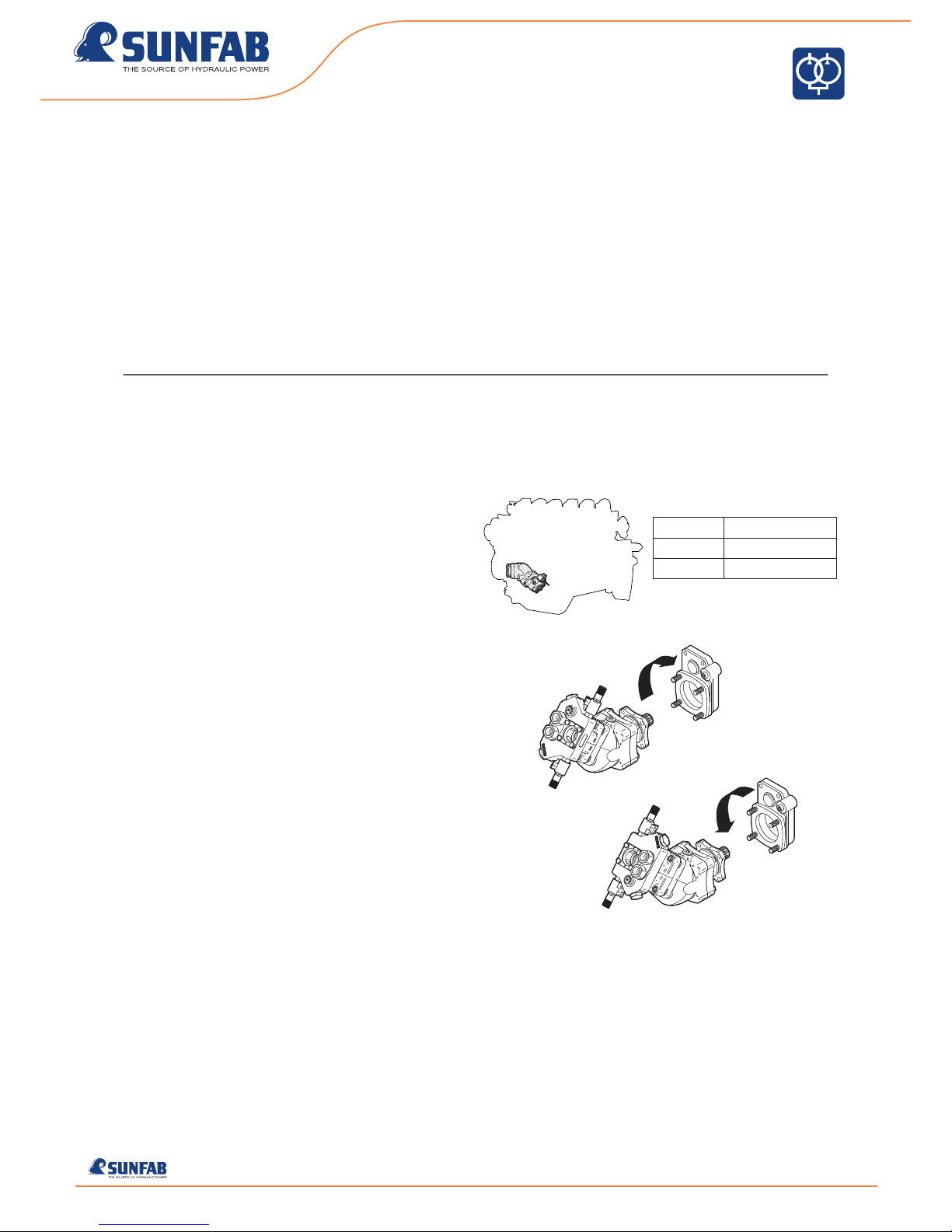
200/200 bar 220 + 116 = 336 Nm
350/350 bar 385 + 203 = 588 Nm
400/400 bar 441 + 232 = 673 Nm
7019EN1809 REV 1.0 1/8
PUMP SCPD 70/36 DIN BY-PASS
EN
INSTRUCTION MANUAL
THANK YOU FOR CHOOSING SUNFAB
You have chosen SCPD 70/36 DIN, a dual flow pump with differentiated
flow suitable for combination vehicles with high power take off ratio and high
output speeds. Compact design and easy installation makes SCPD 70/36
one of the mainstays for powerful, trouble free hydraulic systems
REMEMBER
A trouble-free hydraulic system is created using selected components and
correct installation. Consequently, follow the instructions in this manual,
which includes checking the power take off, tank design, hose dimensions,
installation and start up. Failure to carry out the manufacturer’s installation
conditions will invalidate the warranty.
INSTALLATION REQUIREMENTS
POWER TAKE-OFF
• Pump mounting: Spline shaft DIN 5462 / ISO 14.
Mounting flange ISO 7653-D.
• The power take off can be engine, flywheel or gearbox mounted
• The output speed of the power take off must not exceed the pump’s max
speed, relieved = 2550 rpm
• The permitted torque output on the power take off must be higher than the
pump shaft’s torque at maximum pressure
• The power take off’s direction of rotation must correspond with the selected
pump, which is supplied in left-hand (L) or righthand (R) designs
NOTE! The cover must not be turned to change the direction of rotation.
Sunfab Hydraulics AB, Box 1094, SE-824 12 Hudiksvall, Sweden. Tel: +46 650-367 00, Fax: +46 650-367 27, E-mail: sunfab@ sunfab.se Web: w ww.sunfab.com
2/8
PUMP SCPD 70/36 DIN BY-PASS
1
2
3
4
5 6
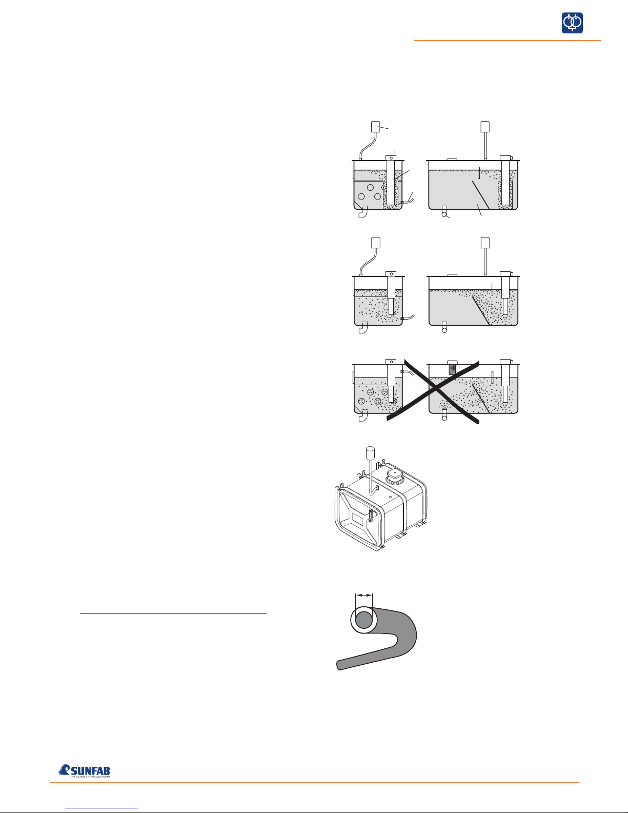
Optional design, solid baf fle plate.
Recommende d design.
Non-recommended design.
d
i
7019EN1809 REV 1.0
Important by installation!
Engine mounted power take-off
requires an internal diameter of
64 mm (2.5”) on suction hose and
connection.
If the suction line is more than 2
m long the internal diameter must
be increased by 10 mm for each
meter extension.
Recommended design
Optional design, solid baffle plate
Non-recommended design
INSTALLATION REQUIREMENTS (Continued)
OIL TANK
The design of the tank is impor tant so that air bubbles are not drawn into
the pump and on into the system. Here are two recommended designs:
1. Air bubbles from the return oil are guided by the oil flow up to the oil
surface (venting area) via an oil pipe mounted at the bottom of the tank.
Another option, yet not as reliable, is a tank with a solid baffle plate as
shown in the middle picture.
2. Eventual drainage hoses is connected close to the
bottom, as far as possible from the suction connection.
3. Large return filter corresponding to 4 x the pump flow.
4. Separate air filter, which is fitted protected from water and dirt.
5. Suction connection close to or in the bottom of the tank on the opposite side to the return filter.
6. The net volume of the tank should be at least 1.5 x the pump flow and
positioned so that the oil level lies above the pump.
A traditional tank fitted with a baffle plate with holes is not recommended
as this does not deaerate the oil satisfactorily.
SUNFAB OIL TANK
This tank is included in the Sunfab range of accessories. It incorporates the
latest advances in tank design to give trouble-free operation.
The tank is available in two material options: stainless steel and aluminium.
PRESSURE RELIEF VALVES
The hydraulic system must be equipped with a pressure relief valve for
each circuit if the flow is used for different functions.
RECOMMENDED LINE SIZE (d
i
)
All dimensions, internal diameter
Max flow 120 lit/min 160 lit/min
Max speed 1 470 rpm 1 850 rpm
Suction hose 50 mm (2”) 64 mm (2½”)
Shut off valve 50 mm (2”) 64 mm (2½”)
Return hose 32 mm (1¼”) 38 mm (1½”)
Pressure hose 19 mm (¾””) 19 mm (¾”)
Sunfab Hydraulics AB, Box 1094, SE-824 12 Hudiksvall, Sweden. Tel: +46 650-367 00, Fax: +46 650-367 27, E-mail: sunfab@ sunfab.se Web: w ww.sunfab.com
3/8
PUMP SCPD 70/36 DIN BY-PASS
A B C D
A
0-20 20 40 60 80 100
C
68
46
32
B C D
A B C D
7019EN1809 REV 1.0
INSTALLATION REQUIREMENTS (Continued)
HYDRAULIC OILS
Quality:
• Mineral oil
Use a high quality oil whose technical properties conform, as a
minimum, to the following requirements:
ISO type HM VG 32-68 depending on the ambient air temperature.
Alternatively DIN 51524-2 HLP.
• Environment oil
Use synthetic ester that conforms to the same technical requirements
as the st andards above.
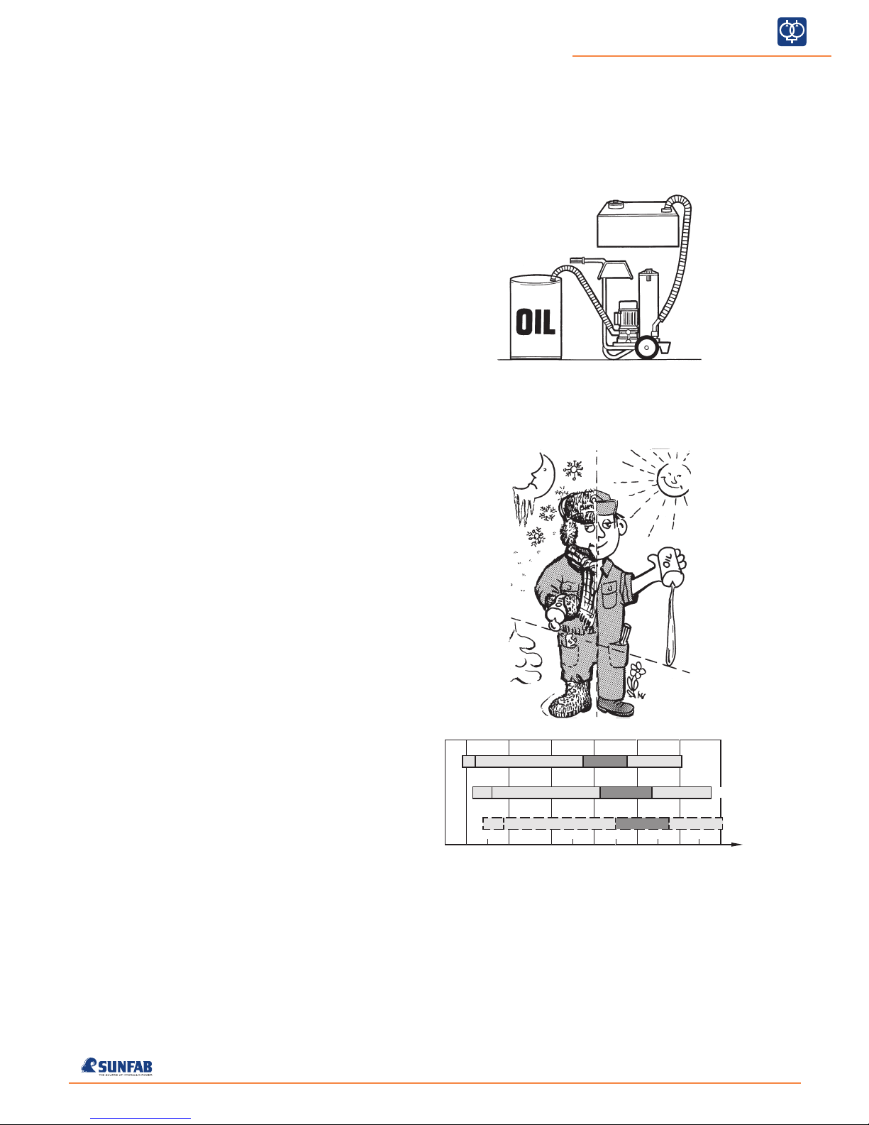
Oil filling - Oil changing:
• New hydraulic oil has a too high impurity level. Filling should therefore
be done with the help of a filter unit or through the oil tank’s return
fil te r.
• Do not mix oil of a dif ferent quality, viscosity or brand. This will impair
the technical proper ties of the oil.
Viscosity:
The viscosity of the hydraulic oil drops (the oil becomes thinner) when the
temperature rises. An ideal choice is an oil with a high viscosity index (VI).
A higher VI gives less viscosity variation when the temperature changes
• At a viscosity higher than 1500 cSt (limit for cold start) the pump cannot
suck in oil
• At a viscosity lower than 10 cSt the lubrication capacity is insufficient.
System efficiency will also be impaired
• When there is a risk of the oil temperature in oil tank to exceed 60 °C, an
oil cooler must be used
Refers to oil temperature in pump
E.g. Hydraulic oil 32: The designation “32” denotes the viscosit y is 32
cSt at 40 °C. Lowest start temperature is -23 °C and highest work ing
temperature 82 °C. Ideal working temperature is 35 - 55 °C.
A
B
C
D
NOTE! The diagram concerns hydraulic oil with viscosity index VI ≈ 180
The hydraulic system can be started but not loaded. Only circulation pumping
at idling speed 1500-700 cSt.
The system can be loaded 700-40 cSt.
Ideal working range 40-20 cSt.
Highest recommended operating temperature 20-10 cSt.
=
=
=
=
 Loading...