

Sunex HD 6744 Owner's Manual
OWNER'S MANUAL
CONTENTS:
Page 1 Specifications
2 Warning Information
3 Setup Instructions and Operating Instructions
4 Preventative Maintenance, Inspection,
Proper Storage and Troubleshooting
5 Owner/User Responsibility and
Warranty Information
6 Exploded View Drawing
7 Replacement Parts
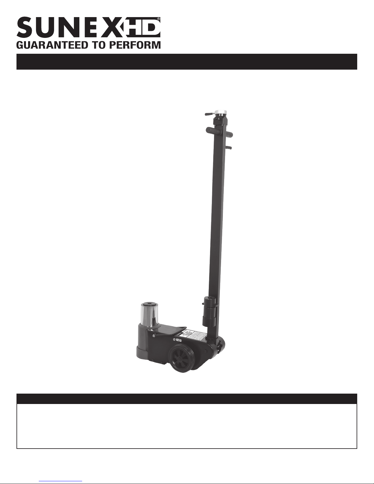
6744
CAPACITY: 44 TON
TRUCK AXLE JACK WITH AIR RETURN
SPECIFICATIONS
Capacity ................................................................. 44 Ton
Minimum Height .......................................................8.25"
Maximum Height .........................................................21"
Ram Travel ..................................................................5.1"
Working psig ........................................................ 116-174
Complies with ASME PASE-2014 Safety Standard © Copyright 2018, Sunex Tools
6744 Rev. 7/16/18
Adapters .........................................................3" and 4.7"
Overall Width ............................................................11.4"
Overall Length .............................................................23"
Handle Length ..........................................................54.3"
Shipping Weight .................................................... 95 lbs.
®
WARNING INFORMATION
This is the safety alert symbol. It is used to alert you
to potential personal injury hazards. Obey all safety
messages that follow this symbol to avoid possible
injury or death.
WARNING
WARNING: Indicates a hazardous situation
which, if not avoided, could result in death
or serious injury.
IMPORTANT: READ THESE INSTRUCTIONS BEFORE OPERATING
BEFORE USING THIS DEVICE, READ THIS MANUAL COMPLETELY AND THOROUGHLY, UNDERSTAND ITS OPERATING PROCEDURES,
SAFETY WARNINGS AND MAINTENANCE REQUIREMENTS.
It is the responsibility of the owner to make sure all personnel read this manual prior to using the device. It is also the responsibility of the
device owner to keep this manual intact and in a convenient location for all to see and read. If the manual or product labels are lost or not
legible, contact Sunex for replacements. If the operator is not fluent in English, the product and safety instructions shall be read to and
discussed with the operator in the operator's native language by the purchaser/owner or his designee, making sure that the operator
comprehends its contents.
THE NATURE OF HAZARDOUS SITUATIONS
WARNING
The use of portable automotive lifting devices is subject to certain hazards that cannot be prevented by mechanical means, but only by the
exercise of intelligence, care, and common sense. It is therefore essential to have owners and personnel involved in the use and operation
of the equipment who are careful, competent, trained, and qualified in the safe operation of the equipment and its proper use. Examples of
hazards are dropping, tipping or slipping of loads caused primarily by improperly securing loads, overloading, off-centered loads, use on
other than hard level surfaces, and using equipment for a purpose for which it was not designed.
METHODS TO AVOID HAZARDOUS SITUATIONS
WARNING
• Read, study, understand and follow all instructions before operating this device.
• Inspect the jack before each use. Do not use jack if damaged, altered, modified, in poor condition, leaking hydraulic fluid, or
unstable due to loose or missing components. Make corrections before using.
• Lift only on areas of the vehicle as specified by the vehicle manufacturer.
• Wear eye protection that meets ANSI Z87.1 and OSHA standards (users and bystanders).
• Do not use jack beyond its rated capacity.
• No persons should be under vehicle when jack is in use.
• This is a lifting device only. Immediately after lifting, support the vehicle with appropriate means.
• No alterations shall be made to this product.
• Use only on a hard level surface.
• Always lower the jack slowly and carefully.
• Do not use saddle adapters or saddle extenders between the stock lifting saddle and the load.
• Failure to heed these warnings may result in serious or fatal personal injury and/or property damage.
WARNING: This product can expose you to chemicals including nickel which is known to the State of California to cause cancer and birth
defects or other reproductive harm. For more information go to www.P65Warnings.ca.gov.
CONSEQUENCES OF NOT AVOIDING HAZARDOUS SITUATIONS
WARNING
Failure to read this manual completely and thoroughly, failure to understand its OPERATING INSTRUCTIONS, SAFETY WARNINGS,
MAINTENANCE INSTRUCTIONS and comply with them, and failure to comply with the METHODS TO AVOID HAZARDOUS SITUATIONS
could cause accidents resulting in serious or fatal personal injury and/or property damage.
6744 2 Rev. 7/16/18
6744
CAPACITY: 44 TON
TRUCK AXLE JACK WITH AIR RETURN
OWNER'S MANUAL
SETUP INSTRUCTIONS
PLEASE REFER TO THE EXPLODED VIEW DRAWING IN THIS MANUAL IN ORDER TO IDENTIFY PARTS.
1. Install the handle assembly (#9) in the chassis (#5) so the holes in the lower portion of the handle line up with the holes in
the chassis. Push the handle yoke (#13) pivot shaft through all the holes and secure the shaft on both ends with the retaining
rings provided.
2. Turn the entire jack on its side in order to hook up the orange and black air hoses that are coming out of the bottom of the handle (#9).
As you are facing the back of the jack, pull the orange and black hoses back towards you and route them over the top of the pivot
shaft (#13) so that they are in line to engage the connectors in the back of the tank (#5). Firmly push the black hose into the connector
(#11) labeled black and the orange hose into the connector (#11) labeled red. Pull on both hoses after they are installed into the
connectors to make sure they are firmly seated. Turn the jack upright.
3. Install an air nipple that is suitable for your shop in the switch assembly (#7). Use pipe dope tape to seal the nipple in the switch
assembly and be careful not to let any excess tape enter the air system. Do not over-tighten the nipple as this could strip the threads
in the switch.
4. Install the adapters (#10 and #19) in the holder at the base of the handle assembly (#9).
5. Hook the shop air line quick disconnect onto the nipple.
6. Due to the back pressure release system design of this jack, the jack’s hydraulic system very rarely becomes air bound. Indication of an
air bound system is a ram that does not rise smoothly. In some extreme case of an air bound system, air can be purged by following
this procedure:
PURGING AIR FROM THE HYDRAULIC SYSTEM
a. Pump the jack to maximum height by turning the air lever all the way to the right. After maximum height is reached, turn the air
lever to the left to lower the jack all the way down.
b. Repeat step “a” several times until all air is purged from the system.
OPERATING INSTRUCTIONS
This is the safety alert symbol used for the OPERATING INSTRUCTIONS section of this manual to alert you to potential personal
injury hazards. Obey all instructions to avoid possible injury or death.
IMPORTANT: Before attempting to raise any vehicle, check vehicle service manual for recommended lifting surfaces.
OPERATION:
1. Become familiar with the identification and function of the operating jack components.
a. The ram (#26) is the shaft that comes out of the jack when you rotate the switch assembly lever (#7) to the right. Lowering the ram
is accomplished by rotating the lever to the left.
b. The saddle (#25) has a hole in it to receive the adapters (#10 and #19). The adapters can be stacked on top of each other for
additional height. Evaluate the work to be done to determine if there is enough ram stroke to lift the load. Adding adapters can
bring the jack closer to the load so you can get more effective ram stroke.
2. Chock the vehicle’s tires that will not be lifted off the ground prior to lifting the vehicle and if available, apply the emergency brake or any
other method of braking.
3. With the jack in its lowered position and the handle all the way down and locked, push the jack under the vehicle and to its designated
lift point. Lock the handle in a position that will not interfere with the vehicle when raised or lowered. Keep the handle in that locked
position until the work is completed and you are ready to remove the jack from use.
4. In most cases, between 116 and 174 psig input air pressure (do not exceed 200 psig) will lift the maximum capacity load. Rotate the
air lever to the right until the top of the ram comes close to the designated lift point. Make sure the designated lift point is flat, parallel
to the ground and free from grease, any kind of lubricant, and debris. Never get under the vehicle when the jack is being used.
Proceed with pumping the jack in order to lift the vehicle to the desired height. During lifting, inspect the position of the jack in relation to
the ground and the ram in relationship to the load to prevent any unstable conditions from developing. If conditions look like they are be
coming unstable, slowly lower the load and make appropriate setup corrections after the load is lowered.
5. When the vehicle or load is lifted to its desired height, immediately place jack stands capable of safely supporting the load in their
designated positions and adjust the stands’ support columns up as close to the designated vehicle support points as possible. Although
jack stands are individually rated, they are used in a matched pair to support one end of the vehicle only. Stands are not to be used to
simultaneously support both ends or one side of a vehicle. Rotate the air lever to the left to lower the vehicle onto the jack stands. Make
sure the vehicle is safely supported by the jack stands’ saddles and not the locating lugs of the saddles. Inspect the relationship of the
jack stands with the ground and the jack stand columns and saddles with the vehicle to prevent any unstable conditions. If conditions
look unstable, rotate the air lever to the right to raise the vehicle off the jack stands. Make appropriate setup changes and slowly and
carefully lower the vehicle onto the jack stands.
6. After the work is done, rotate the air lever to the right until the vehicle is high enough to remove the jack stands from underneath the
vehicle. Rotate the air lever to the left to lower the vehicle to the ground and remove the jack from under the vehicle..
6744 3 Rev. 7/16/18
6744
CAPACITY: 44 TON
TRUCK AXLE JACK WITH AIR RETURN
OWNER'S MANUAL
PREVENTATIVE MAINTENANCE
This is the safety alert symbol used for the PREVENTATIVE MAINTENANCE section of this manual to alert you to potential personal
injury hazards. Obey all instructions to avoid possible injury or death.
IMPORTANT: The number one cause of jack failure in air/hydraulic jacks is dirt and moisture in the air motor and/or hydraulic system.
The shop air supply should be equipped with water and dirt filter traps that should be emptied or cleaned according to a monthly
maintenance schedule. An in line oil lubricator will extend the life of air/hydraulic jacks. Inoperable jacks caused by poorly equipped
or maintained shop air systems are not eligible for warranty consideration. Contaminants can also enter the air/hydraulic system when
the shop air line is disconnected from the jack air line and the line is dropped on the floor. Contaminants in the air couplers, once
reconnected, will be driven into the system.
1. Always store the jack in a well protected area where it will not be exposed to inclement weather, corrosive vapors, abrasive dust, or any
other harmful elements. The jack must be cleaned of water, snow, sand, grit, oil, grease or other foreign matter before using.
2. The jack must be lubricated periodically in order to prevent premature wearing of parts. A general purpose grease must be applied to
the threads on the extension screw. Do not lubricate any portion of the lift saddle and make sure the saddle is free from grease, any kind
of lubricant, or debris before using the jack. Jacks found to be defective due to worn parts resulting from inadequate or no lubrication are
not eligible for warranty consideration.
3. It should not be necessary to refill or top off the reservoir with hydraulic fluid unless there is an external leak. An external leak requires
immediate repair which must be performed in a dirt-free environment by an authorized service center.
IMPORTANT: In order to prevent seal damage and jack failure, never use alcohol, hydraulic brake fluid or transmission oil in the jack.
Use Chevron Hydraulic Oil AW ISO 32 or its equivalent Unocal Unax AW 150.
4. Every jack owner is responsible for keeping the jack labels clean and readable. Use a mild soap solution to wash external surfaces of the
jack but not any moving hydraulic components. Contact Sunex for replacement labels if not readable.
5. Inspect the jack before each use. Do not use the jack if any component is cracked, broken, bent, shows sign of damage or leaks
hydraulic fluid. Do not use the jack if it has loose or missing hardware or components, or is modified in any way. Take corrective
action before using the jack again.
6. Any hydraulic repairs within the warranty period must be performed by an authorized service center.
INSPECTION
Visual inspection should be made before each use of the jack, checking for leaking hydraulic fluid and damaged, loose or missing parts.
Each jack must be inspected by a manufacturer’s repair facility immediately if subjected to an abnormal load or shock. Any jack which
appears to be damaged in any way, is found to be badly worn, or operates abnormally MUST BE REMOVED FROM SERVICE until necessary
repairs are made by a manufacturer’s authorized repair facility. It is recommended that an annual inspection of the jack be made by a
manufacturer’s authorized repair facility and that any defective parts, decals or warning labels be replaced with manufacturer’s specified
parts. A list of authorized repair facilities is available from the manufacturer.
PROPER STORAGE
It is recommended that the jack be stored in a dry location with all wheels touching the ground on a relatively level surface.
TROUBLESHOOTING
PROBLEM ACTION
1. Unit will not lift rated load. Purge air from hydraulic system by following procedure under
SETUP.
2. Unit will not sustain rated load or feels “spongy” under rated load. Purge air from hydraulic system as above.
3. Unit will not lift to full height. Purge air from hydraulic system as above.
4. Handle tends to raise up while the unit is under rated load. Pump the handle rapidly several times to push oil past ball valves in
power unit.
5. Unit still does not operate. Contact Sunex authorized hydraulic service center.
6744 4 Rev. 7/16/18

6744
CAPACITY: 44 TON
TRUCK AXLE JACK WITH AIR RETURN
OWNER'S MANUAL
OWNER/USER RESPONSIBILITY
The owner and/or user must have an understanding of the manufacturer’s operating instructions and warnings before using this jack.
Personnel involved in the use and operation of equipment shall be careful, competent, trained, and qualified in the safe operation of the
equipment and its proper use when servicing motor vehicles and their components. Warning information should be emphasized and
understood. If the operator is not fluent in English, the manufacturer’s instructions and warning shall be read to and discussed with the
operator in the operator’s native language by the purchaser/owner, making sure that the operator comprehends its contents. Owner and/or
user must study and maintain for future reference the manufacturers’ instructions. Owner and/or user is responsible for keeping all warning
labels and instruction manuals legible and intact. Replacement labels and literature are available from the manufacturer.
LIMITED WARRANTY
SUNEX INTERNATIONAL, INC. WARRANTS TO ITS CUSTOMERS THAT THE COMPANY’S SUNEX TOOLS® BRANDED
PRODUCTS ARE FREE FROM DEFECTS IN WORKMANSHIP AND MATERIALS.
Sunex International, Inc. will repair or replace its Sunex Tools® branded products which fail to give satisfactory service due to defective
workmanship or materials, based upon the terms and conditions of the following described warranty plans attributed to that specific
product. This product carries a ONE-YEAR warranty. During this warranty period, Sunex Tools will repair or replace at our option any part
or unit which proves to be defective in material or workmanship.
Other important warranty information
This warranty does not cover damage to equipment or tools arising from alteration, abuse, misuse, damage and does not cover any repairs
or replacement made by anyone other than Sunex Tools® or its authorized warranty service centers. The foregoing obligation is Sunex Tools’
sole liability under this or any implied warranty and under no circumstances shall we be liable for any incidental or consequential damages.
NOTE: Some states do not allow the exclusion or limitation of incidental or consequential damages, so the above limitation or exclusion may
not apply to you. Return equipment or parts to an authorized service center, transportation prepaid. Be certain to include your name and
address, evidence of the purchase date, and description of the suspected defect. If you have any questions about warranty service, please
write to Sunex Tools®. This warranty gives you specific legal rights and you may also have other rights which vary from state to state.
Repair kits and replacement parts are available for many of Sunex Tools products regardless of whether or not the product is still covered by
a warranty plan.
SHIPPING ADDRESS: Sunex Tools • 315 Hawkins Rd. • Travelers Rest, SC 29690
MAILING ADDRESS: Sunex Tools • P.O. Box 1233 • Travelers Rest, SC 29690
6744 5 Rev. 7/16/18
6744
CAPACITY: 44 TON
TRUCK AXLE JACK WITH AIR RETURN
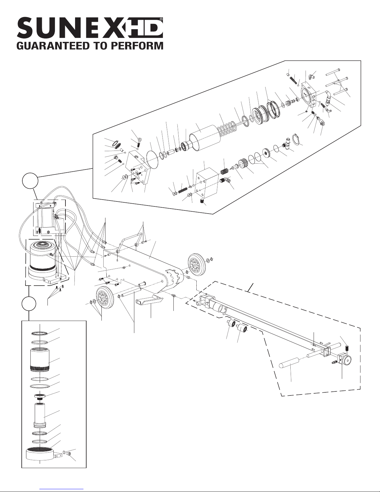
PARTS DRAWING
2
91
90
89
88
87
86
85
47
50
60
77
61
57
51
62
56
52
53
54
55
48
49
43
42
41
40
39
38
33
63
4
95
96
32
34
71
70
94
93
92
66
65
64
3
35
69
72
36
73
74
68
37
75
76
82
83
84
67
81
44
80
45
46
79
58
59
78
5
18
9
17
15
1
16
20
21
22
23
24
25
26
27
28
29
30
14
12
13
11
10
19
6
8
97
7
31
6744 6 Rev. 7/16/18
 Loading...