

Page 1
DROPS
D4.1
Air / Water
Heat Pump
Operating manual and assembly
Version 1.2 19012017
Effect from serial number: 164010111
Page 2

Page 3

-3-
Table of contents
1. Description of Heat Pump 4
2. Construction of Heat Pump 4
3. Installation of Heat Pump 5
3.1 Precautions during installation of the device 5
3.2 Installation recommendations 5
3.3 Connection of hydraulic circuit 5
3.4 Connection of air ducts 5
3.5 Electrical connection 7
3.6 Installation diagram 7
4. Description of controller functions 7
4.1 Control of actuators 8
4.2 Safety 8
4.3 Clock settings 8
4.4 Date settings 8
4.5 Screen settings 8
4.5.1 Screen brightness 8
4.5.2 Screen saver brightness 8
4.6 Programme information 8
5. Installer menu 8
5.1 Tank set point temperature 8
5.2 Anti-freezing 8
5.3 Weekly schedule active 9
5.4 Weekly control of heat pump operation with different levels of temperature 9
5.5 Circulation pump 9
5.6 Language 9
5.7 Service menu 9
5.8 Manual operation 11
5.9 LEGIONELLA settings 11
5.9.1 LEGIONELLA temperature 11
5.9.2 LEGIONELLA duration 11
5.9.3 Maximum LEGIONELLA time 11
5.9.4 LEGIONELLA reminder 11
5.10 Evaporator defrost 11
5.11 Minimum operating temperature 11
5.12 Hysteresis of minimum operating temperature 12
5.13 Heater operation below minimum operating temperature 12
5.13.1 Hysteresis of set point temperature 12
5.13.2 ECO-ECO PLUS threshold temperature 12
5.13.3 Hysteresis of ECO-ECO PLUS threshold 12
5.14 Installation protection 12
5.15 Emergency temperature 12
5.16 Delay compressor 12
5.17 Clear alarm of control temperature 12
5.18 Edit service phone number 12
5.19 Change service code 12
5.20 Factory settings 12
5.21 Sleep Mode 13
6. Security and Alarms 13
7. Maintenance 13
8. SG Ready function 13
9. The procedure after the shelf life of the device 13
10. Hydraulic diagrams 14
10.1 Refrigerant circuit illustration 16
11. Technical data 17
12. Start-up protocol ( 19
13. Start-up protocol ( 21
Copy for the Investor)
Copy for the Manufacturer)
Page 4
Heat pump DROPS D4.1 is a device for utility water heating. It uses the rotary compressor optimised for high
condensation temperatures, i.e. High heating temperatures of utility water. The air flow via the finned coil is forced by
modern, powerful and energy efficient EBM PAPST fan. Water heating is in the SWEP plate exchanger of stainless
steel, and a water circulation is forced by the installed in the heat pump the WILO circulating pump adapted also to work
directly with utility water. The correct operation of the heat pump is ensured by the controller with algorithm optimized for
the heat pump DROPS D4.1 construction. The housing is made of ABS plastic. All the above mentioned
characteristics/components comprise the high quality and efficiency of the heat pump.
Any operations not described in this manual must be carried out in accordance with the accepted rules of installation
knowledge.
1. Description of Heat Pump
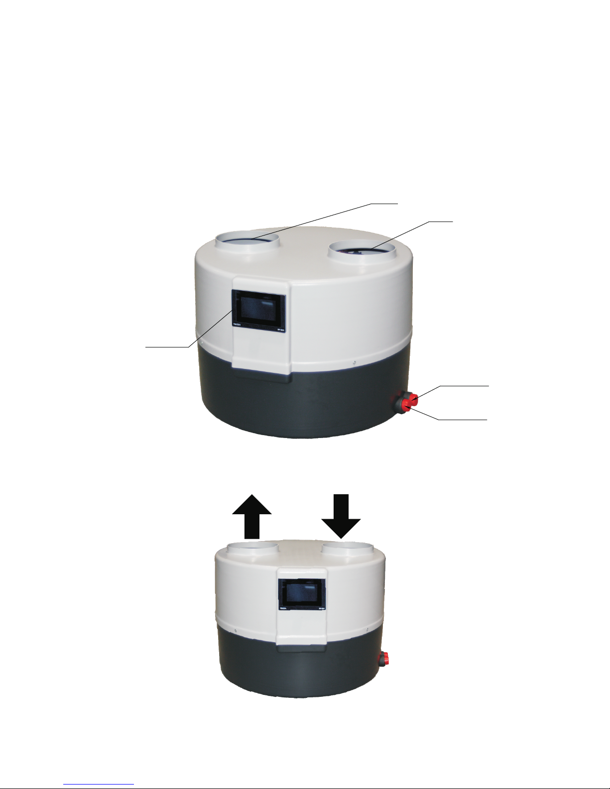
2. Construction of Heat Pump
Control panel
Air inlet
Air outlet
Hot water outlet
Cold water inlet
The power cord is located on the back of the unit
Air outlet Air inlet
-4-
Page 5
The heat pump DROPS D4.1 should be installed in a room where the temperature does not drop below + 5°C. Where
there is a risk of the temperature drop below 5°C, drain the water circulation between the heat pump and the storage
tank and blow out well the installation, e.g. with compressed air.
Level the heat pump during the assembly with the legs of adjustable height. Failure to comply with this
recommendation may result in a defective work and eventually damage to the equipment.
Keep away from divisions (walls ceilings etc.) for smooth maintenance work on the pump heat.
In the lower part of the pump heat housing there is a condensate discharge nozzle to which the hose outlet should be
connected. It is recommended to drain the condensate to the sewage system and to use a siphon.
The heat pump has a built-in automatic air vent that ensures the condenser venting and also the whole heating loop.
The pipeline between the heat pump and the storage tank must have an internal diameter of 20 mm.
On the water return to the heat pump pipeline install an angled filter!!!
The pipelines should be isolated on the whole length!!!
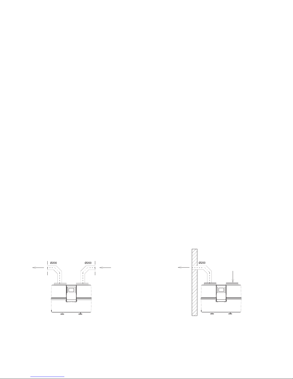
The heat pump has two connectors for connecting the air ducts. The internal diameter of the air ducts must be min.
200mm.
The maximum lengths of the air tubes: 8m
In case of connecting air ducts outside a building one should protect against the air circulation in the winter/
period of sub-zero conditions, when the heat pump is excluded from use.
Installation of the heat pump should be carried out by a person with appropriate qualifications in the field of heating and
cooling devices.
During the installation, one should observe the health and safety regulations which applies in a given country.
3. Installation of Heat Pump
3.2. Installation recommendations
3.3. Connection of hydraulic circuit
3.4. Connection of air ducts
3.1. Connection of air ducts
-5-
AIR ABSORBED FROM ONE ROOM AND DISCHARGED INTO
ANOTHER ONE
AIR ABSORBED FROM THE ROOM AND DISCHARGED
OUTSIDE THROUGH THE WALL
OUTSIDE
AIR
INSIDE
ROOM
Page 6
-6-
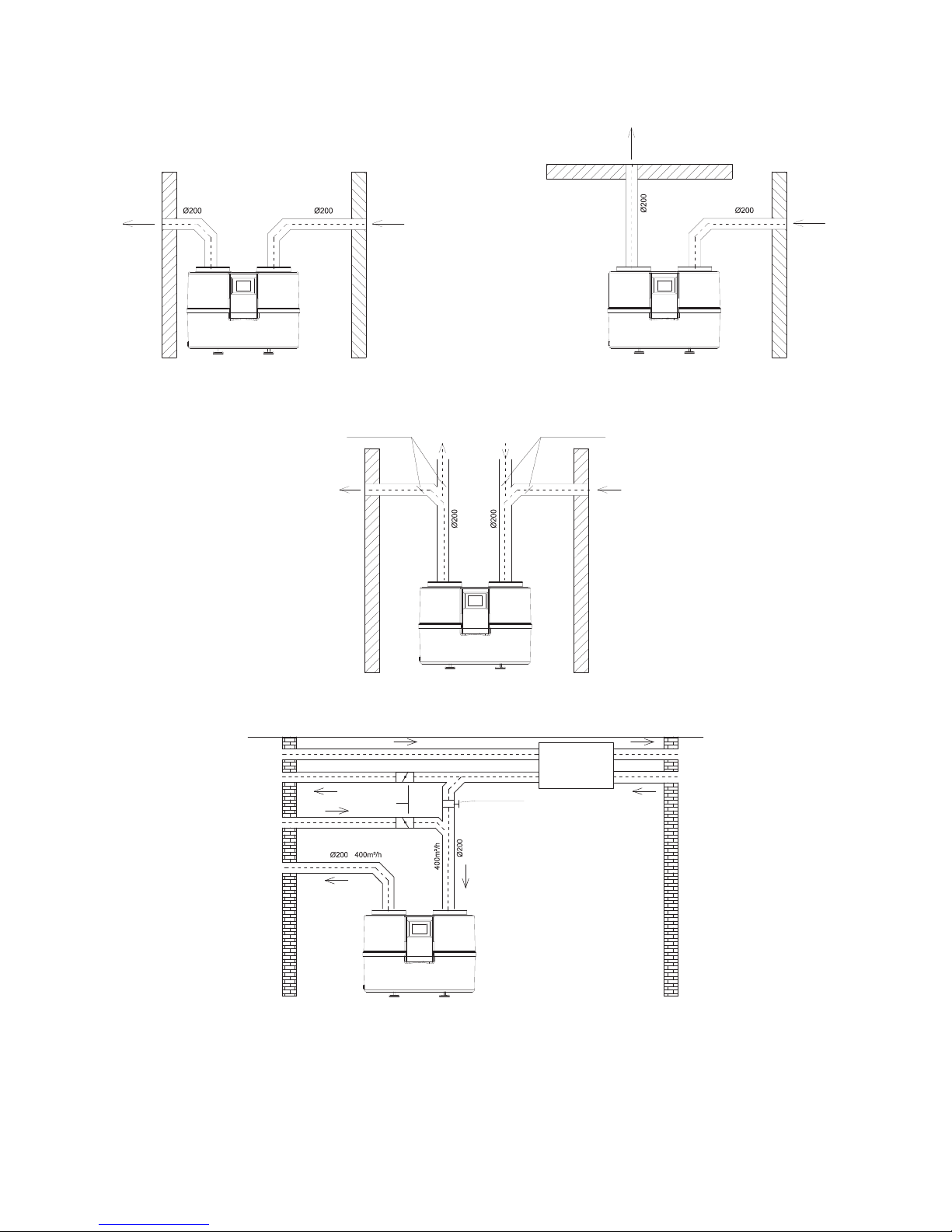
Note: Furthermore the air intake and discharge is allowed from the room in which the pump is installed. But it can result
in reduced energy efficiency.
HEAT PUMP COOPERATING WITH RECUPERATOR
AIR ABSORBED FROM OUTSIDE THROUGH WALL
AND DISCHARGED OUTSIDE THROUGH ROOF
INSIDE ROOM
OUTSIDE
AIR
DISTRIBUTION OF AIR INLET AND DISCHARGED
OUTSIDE
AIR
OUTSIDE
AIR
THROTTLE THROTTLE
INTERNAL
ROOM 1
INTERNAL
ROOM 2
AIR ABSORBED FROM OUTSIDE THROUGH WALL AND
DISCHARGED OUTSIDE THROUGH WALL
OUTSIDE
AIR
OUTSIDE
AIR
OUTSIDE
AIR
OUTSIDE
AIR
AIR SUPPLIED TO
3
ROOMS 150 - 250 m /h
AIR DISCHARGED
FROM ROOMS
Heat pump and recuperative central are working independently of another one so that's why air ducts also
should be separated. The point is, that in time when recuperative is working, but heat pump isn't working this
air freely flow to ventilation box, but not to the heat pump. This would reduce efficiency of the fan recuperative
central.
CHECK VALVE
THROTTLE VALVE
Page 7
The heat pump is powered by 1~230V/50 Hz. As a standard it has a plug with a cable of 1.5 m length.
Important: It is recommended that the electric supply circuit of the heat pump was equipped in the circuit breaker of the
characteristic C and residual current device with rated differential current transmission of 0.03A.
Note: All work related with the installation of these elements should be performed by personnel with the appropriate
permissions and qualifications.
3.5 Electrical connection
3.6 Installation diagram
4. Description of controller functions
-7-
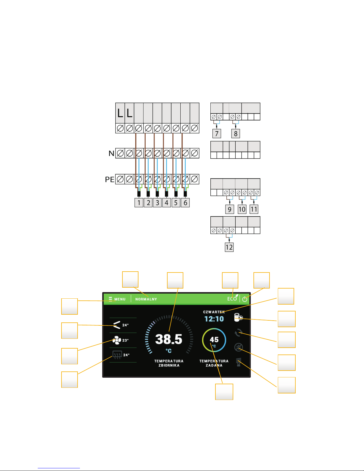
HEATER
VENTILATOR
COMPRESSOR
TANK PUMP
HIGH
PRESSURE
SWITCH
LOW
PRESSURE
SWITCH
SG
SWITCH
EXTERNAL
SENSOR
TANK
SENSOR
CONTROL
SENSOR
EVAPORATOR
SENSOR
DEFROST VALVE
CIRCULATION
PUMP
1
5
4
3
2
6 7 8
9
10
11
12
13
14
1. Evaporator temperature
2. External temperature
3. Control temperature
4. Enter the controller menu
5. Heat pump operation mode
6. Current tank temperature
7. ECO / ECO PLUS mode
8. STANDBY mode icon
9. Current time and day of the week
10. Tank pump icon
11. Circulating pump icon
12. Defrost mode icon
13. Heater icon
14. Pre-set tank temperature
Page 8

Installer menu
Tank set point temperature
Anti-freezing
Weekly schedule active
Weekly schedule
Circulation pump
Language
Service menu
The controller controls the operation of the compressor, ventilator, integrated circulation pump, additional circulation
pump and electrical heater. The compressor is activated with a delay in relation to the circulation pump and ventilator compressor delay parameter.
The electrical heater operates above the ECO-PLUS temperature and in the event of a breakdown.
For the protection of the device against unwanted changes in settings e.g. by children, you can activate the lock - to
operate the controller you must enter the access code.
After selecting the option of Active Protection the controller after a specified period of inactivity (setting Lock Delay)
locks access to the menu functions of the controller. To unlock the driver must enter the four digit code which can be
defined in the PIN Code Change option.
The option allows you to set the current time.
The option allows you to set the current date.
The function allows you to define the brightness of the display during the edit and view of the controller functions in the
range of 10-100%.
The function allows you to define the brightness of the display during the dimming, which is activated in 30 seconds
after the end of the edit and view of the controller functions in the range of 5-100%.
The function allows you to preview the controller information - name of the manufacturer, software number, and service
telephone number.
This function is used to set the tank set-point temperature. The ventilator, the compressor and the pump work until the
tank setpoint temperature is reached.
With this function the user specifies anti-freezing operations, which serve to protect the installation against freezing.
When the temperature drops below a certain temperature threshold (factory set limit is 5°C) the heat pump or the heater
engages permanently; it disengages when the temperature in the circuit reaches a value of temperature threshold
4.1 Control of actuators
4.2 Security
4.3 Clock settings
4.4 Date settings
4.5 Screen brightness
4.5.1 Screen brightness
4.5.2 Screen brightness
4.6 Programme information
5.1 Tank set point temperature
5.2 Anti-freezing
5 Installer menu
-8-
Page 9

increased by 3°C (i.e. in the case of factory settings it will be the value 8°C).
After pressing the encoder the user switches to define the anti-freezing functions. First by turning the encoder selects
the device that is to engage when the temperature drops below a certain threshold: the heater of the heat pump. Next
sets the temperature threshold.
This option allows to enable / disable the activity of weekly control operation. After engaging the functions of weekly
control the pump will work during the selected days of the week and the hours in comfort mode and during the rest in
reduced mode.
The set-point temperatures in modes are not editable and are respectively for the reduced mode: 40°C and for the
comfort mode: 50°C.
The controller is equipped in SG function - in certain conditions (a short circuit of SG) the controller enables a comfort
mode regardless of the weekly programme.
The weekly control will operate correctly after setting the current time and day of the week.
The controller allows to select the settings of two set-point temperature levels of hot utility water - daily and night. The
setpoint temperatures declared for each day of the week in accordance with the specified time periods. For each day
there are two time periods for the daily temperature and two time periods for the night temperature.
The first step when editing the weekly settings is selection of day for which we want to clarify the individual settings. By
turning the encoder the user can select one of the following days of the week, all day (“Entire week"), working days or
weekends ("Saturday and Sunday")
The next step is to select the hours in which the pump has to run in reduced mode and in which in comfort mode. By
turning the encoder move over an hour the setting you want to change and press the encoder. The screen displays the
additional menu:
• Change - selecting this option will change the settings of the selected hour (reduced / comfort mode)
• Copy - will copy settings (reduced / comfort mode) to the adjacent hours - just press the encoder and then turn it
- the settings are copied to subsequent hours.
• Accept - accepts settings for all hours. After pressing this option the screen of Installer Menu is displayed again.
This function is used to activate the connected circulation pump and define individual settings.
After pressing the encoder just select "ON". On the controller display appears a screen for setting the desired operating
time and then the break time.
Next the user selects the days of circulation pump activity: selected day of the week, weekdays or weekends.
The next step is to select hours in which the circulation pump is to be active.
This function allows to set the language of the controller.
To start the service menu of the controller the four-digit access code must be entered. If necessary this code can be
changed to another in the service menu.
5.3 Weekly schedule active
5.4 Weekly control of heat pump operation with different levels of temperature
5.5 Circulation pump
5.6 Language
5.7 Service menu
-9-
Page 10

Service menu
Manual operation
Compressor
Ventilator
Heater
Tank pump
Circulation pump
Defrost valve
Legionella settings
LEGIONELLA temperature
LEGIONELLA duration
LEGIONELLA maximum time
LEGIONELLA reminder
Defrost
Manual defrost
Defrost supervision
Evaporator temperature
Final evaporator temperature
External temperature
Maximum defrost duration
Minimum operating temperature
Hysteresis of minimum operating temperature
Heater operation below minimum operating
temperature
Hysteresis of set point temperature
ECO-ECO PLUS threshold temperature
Hysteresis of ECO-ECO PLUS threshold
Installation protection
Emergency temperature
Delay compressor
Clear alarm of control temperature
Edit service phone number
Change service code
Factory settings
-10-
Page 11

The function allows to enable individual devices regardless to other to verify its operation. Enable individual devices by
pressing the encoder when highlighted: ventilator, compressor, heater, main pump, circulation pump and additional
pump.
LEGIONELLA function is used to disinfect the tank. In the service menu you can configure individual parameters of this
function.
When editing set the desired value by turning the encoder, accept the choice by pressing the encoder.
The function allows to define the set-point temperature of disinfection.
Using this function sets the duration of the disinfection (in minutes) in which the set-point temperature of disinfection
stays at a constant set level (Legionella temperature).
This is the maximum total duration of disinfection (LEGIONELLA function) since the engagement (regardless of the
temperature during the engagement). In the case when the tank does not reach the set-point temperature or does not
maintain for the duration of the LEGIONELLA function set-point temperature, then after a maximum time the controller
will return to the basic operating mode.
When the user activates this function, the controller displays the reminder of disinfection function. The message
appears after 10 days from the last engagement of this function.
Defrosting can occur when the external temperature drops below the T defrost parameter - a parameter set in the
serviceevaporator defrost tab and when the temperature of the evaporator reaches the set value. Defrost is carried out
until the evaporator reaches the end evaporator defrost temperature - a parameter to set in the service tab. Defrost is
limited in time by the max defrost duration parameter. If during this time the evaporator cannot be effectively
defrosted, the heat pump switches to the 10 minute pre-heating cycle, and then again a process of defrosting. After 3
unsuccessful attempts of defrosting the defrost error message is displayed. The heat pump is locked. All the protection
functions remain active. The heat pump reset takes place e.g. when power is disconnected.
Additionally in the controller there is available function of manual defrost - service tab Manual defrosting
should be used in emergency situations (strong evaporator frosting).
In the tab defrost parameter - service, the user can set the following parameters:
evaporator temperature (range from +5°C to -15°C)
final evaporator temperature (range from +5°C to +25°C )
external temperature (range from +10°C to +2°C )
At the certain external temperature or below this temperature thawing is carried out at the set evaporator
temperature or below this temperature. Evaporator temperature at which the thawing is carried out should maintain for
the min. 15s. After this time the evaporator defrost is activated.
In the Service - defrost parameter tab there is located LP monitoring function (low pressure switch) during
defrosting. Functions to select: No LP monitoring, LP monitoring active. In the case of active function of No LP
monitoring the signal from the low pressure switch is not taken into account by the controller during the evaporator
defrost.
5.8 Manual operation
5.9 LEGIONELLA settings
5.9.1 LEGIONELLA temperature
5.9.2 LEGIONELLA duration
5.9.3 LEGIONELLA maximum time
5.9.4 LEGIONELLA reminder
5.10 Evaporator defrost
-11-
This function is used to set the minimum temperature (threshold) of the heat pump activation.
5.11 Minimum operating temperature
Page 12

Hysteresis of minimum operating temperature introduces a tolerance for the activation threshold temperature
preventing unwanted oscillations at activation low temperature fluctuations. This is the difference between the heat
pump activation temperature and the temperature of its deactivation (after the temperature drop).
Example: when the minimum operating temperature is set to 5°C and the hysteresis is set at 2°C, the heat pump
activates at 5°C, but when the temperature drops to a value of 3°C the pump is deactivated.
The user can decide whether the heater is to be enabled below the minimum air temperature.
This option is used to set the tank temperature hysteresis. This is the difference between the set point temperature
(desired on a boiler - when the heat pump turns off) and a temperature of the heat pump return to work.
The ECO - ECO PLUS threshold is a tank temperature at which the generator is turned off and further tank post heating
starts to be carried out using the heater or/and an additional heat source.
This option is used to set the temperature hysteresis for the ECO - ECO PLUS threshold (disconnection of the unit and
the engagement of an additional heat source), in order to prevent unnecessary oscillations. This is the difference
between the temperature of threshold disengagement of the generator and the temperature of the generator return to
work (after the temperature drop below the ECO - ECO PLUS threshold).
The operation of the installation protection depends on the pressure switch (the pressure sensor).
In the event of the engagement of this function, the signal of the pressure switch with too high pressure disables the
pump and triggers the alarm.
The emergency temperature is a parameter protecting the compressor and the generator from overheating. In the
event of a dangerous increase in the temperature of the control sensor (up to an emergency temperature) 3 times within
an hour the generator disengages permanently. In this case the restart of the device is only possible via the heat pump
manufacturer service.
After starting the heat pump, first engages the ventilator and the pump, and then after a few seconds, the compressor.
This setting adjusts the time delay of the compressor engagement after the ventilator and the pump. When the pump is
about to disengage (e.g.: the ECO - ECO PLUS threshold temperature is to be reached), first the compressor is
disengaged and after a set time delay, the ventilator and the pump.
This parameter is closely linked with the emergency temperature function. If the control temperature exceeds the
emergency threshold 3 times within an hour, it is possible to heat only with the heater.
Using this setting it is possible to edit the service phone number, which is displayed in the user menu: Information. Set
the desired value by turning the encoder, accept the choice by pressing the encoder.
With this function you can change the access code to the service menu. Set the desired value by turning the encoder,
accept the choice by pressing the encoder.
The controller is pre-configured to work. However, it should be adjusted to your needs. You can return to the factory
settings at any time. When enabling the option of factory settings all custom settings of the heat pump are lost (stored in
user menu) to the settings stored by the controller manufacturer. From this point you can re-set your own service
parameters of the heat pump.
5.12 Hysteresis of minimum operating temperature
5.13 Heater operation below minimum operating temperature
5.13.1 Hysteresis of set point temperature
5.13.2 ECO-ECO PLUS threshold temperature
5.13.3 Hysteresis of ECO-ECO PLUS threshold
5.14 Installation protection
5.15 Emergency temperature
5.16 Delay compressor
5.17 Clear alarm of control temperature
5.18 Edit service phone number
5.19 Change service code
5.20 Factory settings
-12-
Page 13

When you press and hold for a few seconds the sleep mode button (standby) on the main screen of the controller, the
installation actuators are disconnected. The anti-freezing function remains active - in the event of temperature drop
below the certain threshold the heat pump or the heater enables. This button is used when it is necessary to shut off
immediately all the devices.
In order to ensure the maximum safe and defect-free operation the regulator has several security features. In the event
of an alarm the audible signal enables and a corresponding message appears on the display.
In the ST-520 controller before and during the heating season check the technical condition of the wiring. Check also
the controller mounting, clean of dust and other pollutants.
User of device are requested at lest in a year to make service activities, which should including for example:
• cleaning of vaporizer
• cleaning case and the base of heat pump
• cleaning filter localized in hydraulic instalation
• check of electric patches
Attention: Before start service activities you should disconnect heat pump and electric grid!
Heat pump is protected by pressure switches with automatic reset, installed in refrigerant circuit by side of low and high
pressure. Pressure switches are connected direct to the driver. Freeing any of the pressure switches cause stop
working of circulation pump and appearance sound signal.
Additional air-compressor is safed by the sensor of hot gas.
The heat pump DROPS D4.1 was designed to work with the installations of photovoltaic panels and operating in energy
tariffs. The controller has an additional potential-free NO contact. After triggering the contact the heat pump and HUW
tank loading is enabled up to the daily set-point temperature.
After the shelf life of the device, you should contact a person with the appropriate permissions in the field of recovery
and disposal/utilization of controlled substances.
After emptying the device from the refrigerant the device can be given to disposal/utilization and / or individual
components can be recycled.
5.21 Sleep Mode
6. Security and Alarms
7. Maintenance
8. SG Ready function
9. The procedure after the shelf life of the device
CAUSE
Generator
breakdown
All the devices except
the heater are disabled
- exceeding the maximum
temperature in the system
The alarm clears itself when
the temperature drops
- defective external sensor
Replace the external sensor
Installation
failure
All the devices except
the heater are disabled
Too high pressure in the
system
The alarm clears itself when
the pressure drops
Tank sensor
failure
No device is operating
Defective tank sensor
Replace the tank sensor
Control sensor
failure
- On the main display
appears an appropriate
message
Defective control sensor
Replace the control sensor
-13-
Page 14

10. Hydraulic diagrams
-14-
CHUW
HUW
TO INLET Ø200
1 – HEAT PUMP
2 – BALL VALVE
3 – CIRCULATION PUMP
4 – CHECK VALVE
5 – DIAPHRAGM PRESSURE EXPANSION VESSELS
6 – SECURITY VALVE
7 – HUW TANK
8 – SECURITY VALVE
9 - DIAPHRAGM PRESSURE EXPANSION VESSELS
10 – INLET STRAINER
TO OUTLET Ø200
CW
Page 15

-15-
CHUW
HUW
TO INLET Ø200
TO OUTLET Ø200
1 – HEAT PUMP GELBI
2 – BALL VALVE
3 – CIRCULATION PUMP
4 – CHECK VALVE
5 – DIAPHRAGM PRESSURE EXPANSION VESSELS
6 – SECURITY VALVE
7 – HUW TANK
8 – INLET STRAINER
CW
Page 16

-16-
10.1. Refrigerant circuit illustration
Page 17

-17-
11. Technical data
The above values of COP and heating times were established in the following conditions: Drawn air temperature: 20°C.
The pump connected directly to the water tank. The air drawn directly from the room. In different conditions the above
values may change.
Scope
External temperature
min/max [°C]
+
5
/ +43
The temperature of hot water with the heat pump MAX °C 60
°C
60
The temperature of the hot water with the electrical heater.
°C
75
Minimum installation area
Heat-carrying agent
Electrical power supply:
2
m
1
Water
1/N/PE 220-240V/50Hz
-
-
Electrical parametres
Recommended security
COP, water heating 10 ÷ 40°C:
COP, water heating 10 ÷ 45°C:
COP, water heating 10 ÷ 50°C:
COP, water heating 10 ÷ 55°C:
Heating time for 100 L water at 10 ÷ 40°C:
Heating time for 100 L water at 10 ÷ 45°C:
Heating time for 100 L water at 10 ÷ 50°C:
Heating time for 100 L water at 10 ÷ 55°C:
Maximum heating capacity for drawn air
temperature of 20°C:
Average heating capacity for drawn air
temperature of 20°C and water heating
from 10 to 55 °C:
Energy consumption for drawn air temperature
of 20°C:
A
A
A
W
W
C6
min 0,29kW, max. 0,560kW
1,98 kW
1,49 kW
4,33
3,98
3,55
3,22
2h:27min
3h:07min
3h:57min
4h:38min
Max. starting electricity of the heat pump
Max. work electricity of the heat pump
Power of absorb
15,2
3
90
fan
max 55
circulation pump
Page 18

-18-
The above values of COP and heating times were established in the following conditions: Drawn air temperature: 35°C.
The pump connected directly to the water tank. The air drawn directly from the room. In different conditions the above
values may change.
Scope
External temperature
min/max [°C]
+
5
/ +43
The temperature of hot water with the heat pump MAX °C 60
°C
60
The temperature of the hot water with the electrical heater.
°C
75
Minimum installation area
Heat-carrying agent
Electrical power supply:
2
m
1
Water
1/N/PE 220-240V/50Hz
-
-
Electrical parametres
Recommended security
COP, water heating 10 ÷ 40°C:
COP, water heating 10 ÷ 45°C:
COP, water heating 10 ÷ 50°C:
COP, water heating 10 ÷ 55°C:
Heating time for 100 L water at 10 ÷ 40°C:
Heating time for 100 L water at 10 ÷ 45°C:
Heating time for 100 L water at 10 ÷ 50°C:
Heating time for 100 L water at 10 ÷ 55°C:
Maximum heating capacity for drawn air
temperature of 35°C:
Average heating capacity for drawn air
temperature of 35°C and water heating
from 10 to 55 °C:
Energy consumption for drawn air temperature
of 35°C:
A
A
A
W
W
C6
min 0,29kW, max. 0,65kW
2,57 kW
1,9 kW
6,9
6,6
5,7
4,9
1,5h
1,9h
2,6h
3,4h
Max. starting electricity of the heat pump
Max. work electricity of the heat pump
Power of absorb
15,2
3
90
fan
max 55
circulation pump
Working factor
Refrigerant/ quantity type/kg
R134a/ 0,6 kg
Maximum permissible pressure (low pressure)
bar
7
Maximum permissible pressure (high pressure)
bar
23
Dimensions
Diameter
Ø mm
668
Height
mm
512
Weight
kg
45
Heating circuit parameters
Connectors for the heating circuit
cal
2xGW 3/4"
Minimum tube inside diameter
mm
20
Flow
3
m /h
0,280
Working factor
-
water/propylene glycol
Compressor type
Type of the air-compressor oil
rotary
ATMOS-RB68EP/FVC68D Quantity: 320 ml ±20
The producer is reserving the right for changes of included information in the instruction
Page 19

-19-
Copy for the Investor
Device serial no
Name and address of the Investor
Name and surname of
the actuating person
Place of installation
(e.g. cellar)
Air ducts
Diameter: Material:
Heating pipeline
Diameter: Material:
Heating diagram corresponding
with the operating instructions
HUW tank capacity
Feed temp. - heat pump*
Return temp. - heat pump*
.............................................. ...................................................... ........................................
Stamp/signature of dealer Stamp/signature of installing company Signature of investor
Diagram no: Other:
Start-up protocol of the heat pump DROPS D4.1
Condensate drainage
method
Electrical connection
Name and surname of
the person performing
Overcurrent Protection
Residual-current
device
Cross-section of
the power cord
Heater Yes No Circulation pump Yes No
Notes
Start-up date
* Note the temperature of the storage container down during the measurement. The temperature of the storage
container during the measurement should not be lower than 30ºC.
Page 20

-20-
Page 21

-21-
Start-up protocol of the heat pump DROPS D4.1
Copy for the Manufacturer of a device1
.............................................. ...................................................... ........................................
Stamp/signature of dealer Stamp/signature of installing company Signature of investor
1
In the event of malfunction of the heat pump “The start-up protocol” is attached to the complaint notification, to be sent
to the manufacturer. The Protocol is the basis for defining the correctness of the selection and installation method of
the device.
Device serial no
Name and address of the Investor
Name and surname of
the actuating person
Place of installation
(e.g. cellar)
Air ducts
Diameter: Material:
Heating pipeline
Diameter: Material:
Heating diagram corresponding
with the operating instructions
HUW tank capacity
Feed temp. - heat pump*
Return temp. - heat pump*
Diagram no: Other:
Condensate drainage
method
Electrical connection
Name and surname of
the person performing
Overcurrent Protection
Residual-current
device
Cross-section of
the power cord
Heater Yes No Circulation pump Yes No
Notes
Start-up date
* Note the temperature of the storage container down during the measurement. The temperature of the storage
container during the measurement should not be lower than 30ºC.
Page 22

-22-
Page 23

-23-
Page 24

 Loading...