

Page 1

Avaya Call Management System
Sun Enterprise 3500 Computer
Hardware Installation, Maintenance, and
Troubleshooting
585-215-873
Issue 6.0
May 2005
Page 2

© 2005 Avaya Inc.
All Rights Reserved.
Notice
While reasonable efforts were made to ensure that the information in this
document was complete and accurate at the time of printing, Avaya Inc.
can assume no liability for any errors. Changes and corrections to the
information in this document may be incorporated in future releases.
Documentation disclaimer
Avaya Inc. is not responsible for any modifications, additions, or deletions
to the original published version of this documentation unless such
modifications, additions, or deletions were performed by Avaya.
Customer and/or End User agree to indemnify and hold harmless Avaya,
Avaya's agents, servants and employees against all claims, lawsuits,
demands and judgments arising out of, or in connection with, subsequent
modifications, additions or deletions to this documentation to the extent
made by the Customer or End User.
Link disclaimer
Avaya Inc. is not responsible for the contents or reliability of any linked
Web sites and does not necessarily endorse the products, services, or
information described or offered within them. We cannot guarantee that
these links will work all of the time and we have no control over the
availability of the linked pages.
Warr ant y
Avaya Inc. provides a limited warranty on this product. Refer to your
sales agreement to establish the terms of the limited warranty. In
addition, Avaya’s standard warranty language, as well as information
regarding support for this product, while under warranty, is available
through the following Web site:
http://www.avaya.com/support
Preventing toll fraud
"Toll fraud" is the unauthorized use of your telecommunications system
by an unauthorized party (for example, anyone who is not a corporate
employee, agent, subcontractor, or person working on your company's
behalf). Be aware that there may be a risk of toll fraud associated with
your system and that, if toll fraud occurs, it can result in substantial
additional charges for your telecommunications services.
Avaya fraud intervention
If you suspect that you are being victimized by toll fraud and you need
technical assistance or support, call Technical Service Center Toll Fraud
Intervention Hotline at +1-800-643-2353 for the United States and
Canada. For additional support telephone numbers, see the Avaya Web
site:
http://www.avaya.com/support
Providing telecommunications security
Telecommunications security (of voice, data, and video communications)
is the prevention of any type of intrusion to (that is, either unauthorized or
malicious access to or use of) your company's telecommunications
equipment by some party.
Your company's "telecommunications equipment" includes both this
Avaya product and any other voice/data/video equipment that could be
accessed via this Avaya product (that is, "networked equipment").
An "outside party" is anyone who is not a corporate employee, agent,
subcontractor, or person working on your company's behalf. Whereas, a
"malicious party" is anyone (including someone who may be otherwise
authorized) who accesses your telecommunications equipment with
either malicious or mischievous intent.
Such intrusions may be either to/through synchronous (time-multiplexed
and/or circuit-based) or asynchronous (character-, message-, or
packet-based) equipment or interfaces for reasons of:
• Use (of capabilities special to the accessed equipment)
• Theft (such as, of intellectual property, financial assets, or
toll-facility access)
• Eavesdropping (privacy invasions to humans)
• Mischief (troubling, but apparently innocuous, tampering)
• Harm (such as harmful tampering, data loss or alteration,
regardless of motive or intent)
Be aware that there may be a risk of unauthorized intrusions associated
with your system and/or its networked equipment. Also realize that, if
such an intrusion should occur, it could result in a variety of losses to your
company (including, but not limited to, human and data privacy,
intellectual property, material assets, financial resources, labor costs, and
legal costs).
Your responsibility for your company's telecommunications
security
The final responsibility for securing both this system and its networked
equipment rests with you, an Avaya customer's system administrator,
your telecommunications peers, and your managers. Base the fulfillment
of your responsibility on acquired knowledge and resources from a
variety of sources, including, but not limited to:
• Installation documents
• System administration documents
• Security documents
• Hardware-/software-based security tools
• Shared information between you and your peers
• Telecommunications security experts
To prevent intrusions to your telecommunications equipment, you and
your peers should carefully program and configure:
• Your Avaya-provided telecommunications systems and their
interfaces
• Your Avaya-provided software applications, as well as their
underlying hardware/software platforms and interfaces
• Any other equipment networked to your Avaya products.
Trademarks
Avaya is a trademark of Avaya Inc.
All non-Avaya trademarks are the property of their respective owners.
Document ordering information:
Avaya Publications Center
Voi ce: +1-207-866-6701
Fax: +1-207-626-7269
Write: Globalware Solutions
Web: http://www.avaya.com/support
E-mail: [email protected]
Order: Document No. 585-215-873, Issue 6.0
For the most current versions of documentation, go to the Avaya support
Web site:
http://www.avaya.com/support
COMPAS
This document is also available from the COMPAS database. The
COMPAS ID for this document is 79854.
Avaya support
Avaya provides a telephone number for you to use to report problems or
to ask questions about your contact center. The support telephone
number is 1-800-242-2121 in the United States. For additional support
telephone numbers, see the Avaya Web site:
http://www.avaya.com/support
1-800-457-1764 (Toll-free, U.S. and Canada only)
1-800-457-1764 (Toll-free, U.S. and Canada only)
200 Ward Hill Avenue
Haverhill, MA 01835 USA
Attention: Avaya Account Manager
May 2005
Page 3

Avaya Call Management System
Sun Enterprise 3500 Computer
Hardware Installation, Maintenance, and Troubleshooting
Contents
Preface . . . . . . . . . . . . . . . . . . . . . . . . . . . . . . . . . . . . . . . . 9
Purpose . . . . . . . . . . . . . . . . . . . . . . . . . . . . . . . . . . . . . . . . 10
Intended users . . . . . . . . . . . . . . . . . . . . . . . . . . . . . . . . . . . . . 10
Overview . . . . . . . . . . . . . . . . . . . . . . . . . . . . . . . . . . . . . . . 11
Conventions and terminology . . . . . . . . . . . . . . . . . . . . . . . . . . . . . . 11
Reasons for reissue . . . . . . . . . . . . . . . . . . . . . . . . . . . . . . . . . . 12
Related documentation . . . . . . . . . . . . . . . . . . . . . . . . . . . . . . . . . 14
Change description . . . . . . . . . . . . . . . . . . . . . . . . . . . . . . . . . . 14
Software documents . . . . . . . . . . . . . . . . . . . . . . . . . . . . . . . . . 14
Administration documents . . . . . . . . . . . . . . . . . . . . . . . . . . . . . . . 15
Avaya CMS upgrade documents . . . . . . . . . . . . . . . . . . . . . . . . . . . . 15
Base load upgrades . . . . . . . . . . . . . . . . . . . . . . . . . . . . . . . . 15
Platform upgrades and data migration . . . . . . . . . . . . . . . . . . . . . . . . 16
Avaya Call Management System Upgrade Express (CUE) . . . . . . . . . . . . . . 16
Hardware documents . . . . . . . . . . . . . . . . . . . . . . . . . . . . . . . . . 17
Communication Manager documents. . . . . . . . . . . . . . . . . . . . . . . . . . 17
Documentation Web sites . . . . . . . . . . . . . . . . . . . . . . . . . . . . . . . 18
Support . . . . . . . . . . . . . . . . . . . . . . . . . . . . . . . . . . . . . . . . 18
Installation . . . . . . . . . . . . . . . . . . . . . . . . . . . . . . . . . . . . . . . . 19
Preparing for installation . . . . . . . . . . . . . . . . . . . . . . . . . . . . . . . . 20
Safety precautions . . . . . . . . . . . . . . . . . . . . . . . . . . . . . . . . . . 20
System precautions . . . . . . . . . . . . . . . . . . . . . . . . . . . . . . . . . . 21
Required tools . . . . . . . . . . . . . . . . . . . . . . . . . . . . . . . . . . . . 21
Electrical specifications . . . . . . . . . . . . . . . . . . . . . . . . . . . . . . . . 22
Physical specifications . . . . . . . . . . . . . . . . . . . . . . . . . . . . . . . . 22
Service access specifications . . . . . . . . . . . . . . . . . . . . . . . . . . . . . 23
Environmental specifications. . . . . . . . . . . . . . . . . . . . . . . . . . . . . . 23
Unpacking and inventorying the equipment . . . . . . . . . . . . . . . . . . . . . . . 24
Parts list . . . . . . . . . . . . . . . . . . . . . . . . . . . . . . . . . . . . . . . 25
Determining the computer model. . . . . . . . . . . . . . . . . . . . . . . . . . . . 26
Features . . . . . . . . . . . . . . . . . . . . . . . . . . . . . . . . . . . . . . 26
Physical labeling . . . . . . . . . . . . . . . . . . . . . . . . . . . . . . . . . . 26
Software check. . . . . . . . . . . . . . . . . . . . . . . . . . . . . . . . . . . 27
Computer layout . . . . . . . . . . . . . . . . . . . . . . . . . . . . . . . . . . . 28
Hardware options . . . . . . . . . . . . . . . . . . . . . . . . . . . . . . . . . . . 29
Assembling the Enterprise 3500 computer . . . . . . . . . . . . . . . . . . . . . . . . 30
Issue 6.0 May 2005 3
Page 4

Contents
Peripheral connectivity and parts list. . . . . . . . . . . . . . . . . . . . . . . . . . . 40
Connecting the monitor and keyboard . . . . . . . . . . . . . . . . . . . . . . . . . . 42
Connecting the remote console modem . . . . . . . . . . . . . . . . . . . . . . . . . 44
Connecting the switch link . . . . . . . . . . . . . . . . . . . . . . . . . . . . . . . 45
Powering up the system and verifying POST. . . . . . . . . . . . . . . . . . . . . . . 46
Identifying installed I/O cards . . . . . . . . . . . . . . . . . . . . . . . . . . . . . . 49
Setting the remote console modem options . . . . . . . . . . . . . . . . . . . . . . . 51
Turning the system over for provisioning. . . . . . . . . . . . . . . . . . . . . . . . . 57
Installing the fiber-cable organizer . . . . . . . . . . . . . . . . . . . . . . . . . . . 30
Connecting the AC power cord . . . . . . . . . . . . . . . . . . . . . . . . . . . . 32
Fiber channel disk cabling . . . . . . . . . . . . . . . . . . . . . . . . . . . . . . . 34
Connecting the fiber cable to the FC-AL interface board . . . . . . . . . . . . . . . 35
Wrapping the fiber cable on the organizer . . . . . . . . . . . . . . . . . . . . . . 36
Connecting the fiber cable to the I/O board . . . . . . . . . . . . . . . . . . . . . 38
Attaching the SCSI terminator . . . . . . . . . . . . . . . . . . . . . . . . . . . . . 39
Sportster 33.6 faxmodem . . . . . . . . . . . . . . . . . . . . . . . . . . . . . . . 51
Paradyne Comsphere 3910 modem . . . . . . . . . . . . . . . . . . . . . . . . . . 52
Recommended options . . . . . . . . . . . . . . . . . . . . . . . . . . . . . . . 52
Option buttons . . . . . . . . . . . . . . . . . . . . . . . . . . . . . . . . . . . 52
Setting the options . . . . . . . . . . . . . . . . . . . . . . . . . . . . . . . . . 53
Maintenance . . . . . . . . . . . . . . . . . . . . . . . . . . . . . . . . . . . . . . . . 59
ESD precautions . . . . . . . . . . . . . . . . . . . . . . . . . . . . . . . . . . . . 59
Computer layout . . . . . . . . . . . . . . . . . . . . . . . . . . . . . . . . . . . . 60
Maintaining boards . . . . . . . . . . . . . . . . . . . . . . . . . . . . . . . . . . . 61
Identifying free board slots. . . . . . . . . . . . . . . . . . . . . . . . . . . . . . . 61
Removing and installing boards . . . . . . . . . . . . . . . . . . . . . . . . . . . . 62
Precautions for handling boards. . . . . . . . . . . . . . . . . . . . . . . . . . . 63
Removing a board . . . . . . . . . . . . . . . . . . . . . . . . . . . . . . . . . 63
Installing a board . . . . . . . . . . . . . . . . . . . . . . . . . . . . . . . . . . 64
Resetting the EEPROM settings . . . . . . . . . . . . . . . . . . . . . . . . . . 64
Synchronizing the clocks . . . . . . . . . . . . . . . . . . . . . . . . . . . . . . 65
Maintaining the system clock board . . . . . . . . . . . . . . . . . . . . . . . . . . 66
Replacing the system clock board . . . . . . . . . . . . . . . . . . . . . . . . . . 66
Setting the boot device on a new NVRAM chip . . . . . . . . . . . . . . . . . . . . 67
Synchronizing the clocks . . . . . . . . . . . . . . . . . . . . . . . . . . . . . . 68
Maintaining I/O cards . . . . . . . . . . . . . . . . . . . . . . . . . . . . . . . . . . 69
Required references . . . . . . . . . . . . . . . . . . . . . . . . . . . . . . . . . 69
I/O card compatibility with CMS loads . . . . . . . . . . . . . . . . . . . . . . . . . 70
SunFastEthernet I/O card. . . . . . . . . . . . . . . . . . . . . . . . . . . . . . 70
Installing or removing I/O cards . . . . . . . . . . . . . . . . . . . . . . . . . . . . 70
Installing HSI/S cards . . . . . . . . . . . . . . . . . . . . . . . . . . . . . . . . . 73
Installing the first HSI/S card . . . . . . . . . . . . . . . . . . . . . . . . . . . . 73
Installing HSI/S software and patches . . . . . . . . . . . . . . . . . . . . . . . . 75
Setting up the switch link for each ACD . . . . . . . . . . . . . . . . . . . . . . . 75
Adding a second HSI/S card . . . . . . . . . . . . . . . . . . . . . . . . . . . . 76
Maintaining disk drives . . . . . . . . . . . . . . . . . . . . . . . . . . . . . . . . . 78
4 Avaya CMS Sun Enterprise 3500 Computer Hardware Installation, Maintenance, and Troubleshooting
Page 5

Disk drive compatibility with CMS loads . . . . . . . . . . . . . . . . . . . . . . . . 78
Prerequisites . . . . . . . . . . . . . . . . . . . . . . . . . . . . . . . . . . . . . 78
Required references . . . . . . . . . . . . . . . . . . . . . . . . . . . . . . . . . 79
Adding or replacing disk drives. . . . . . . . . . . . . . . . . . . . . . . . . . . . . 79
Powering down the system . . . . . . . . . . . . . . . . . . . . . . . . . . . . . 79
Installing the new drives . . . . . . . . . . . . . . . . . . . . . . . . . . . . . . 80
Powering up the system . . . . . . . . . . . . . . . . . . . . . . . . . . . . . . 81
Setting up the disk drives . . . . . . . . . . . . . . . . . . . . . . . . . . . . . . . 82
Partitioning disk drives . . . . . . . . . . . . . . . . . . . . . . . . . . . . . . . . 84
R3V11 and R12 . . . . . . . . . . . . . . . . . . . . . . . . . . . . . . . . . . 84
R3V9 . . . . . . . . . . . . . . . . . . . . . . . . . . . . . . . . . . . . . . . 84
R3V8 and earlier . . . . . . . . . . . . . . . . . . . . . . . . . . . . . . . . . . 84
Disk partition values . . . . . . . . . . . . . . . . . . . . . . . . . . . . . . . . 85
Partitioning and formatting a disk . . . . . . . . . . . . . . . . . . . . . . . . . . 90
Administering data disk drives . . . . . . . . . . . . . . . . . . . . . . . . . . . . . 94
Administering new data disks, R3V9 and later . . . . . . . . . . . . . . . . . . . . 94
Administering replacement data disks, R3V9 and later . . . . . . . . . . . . . . . . 95
Administering a new data disk, R3V8 and earlier, nonmirrored . . . . . . . . . . . . 95
Administering a new pair of data disks, R3V8 and earlier, mirrored . . . . . . . . . . 99
Administering a replacement data disk, R3V8 and earlier, nonmirrored . . . . . . . . 102
Administering a replacement disk, R3V8 and earlier, mirrored. . . . . . . . . . . . . 105
Replacing the CD-ROM or DVD-ROM drive . . . . . . . . . . . . . . . . . . . . . . 106
Maintaining tape drives . . . . . . . . . . . . . . . . . . . . . . . . . . . . . . . . . 109
Tape drive compatibility . . . . . . . . . . . . . . . . . . . . . . . . . . . . . . . . 109
DDS4 tape drive . . . . . . . . . . . . . . . . . . . . . . . . . . . . . . . . . . 109
Ordering tapes . . . . . . . . . . . . . . . . . . . . . . . . . . . . . . . . . . . . 110
Cleaning the tape drive . . . . . . . . . . . . . . . . . . . . . . . . . . . . . . . . 110
DDS4 tape drive . . . . . . . . . . . . . . . . . . . . . . . . . . . . . . . . . . 110
Exabyte Mammoth tape drive . . . . . . . . . . . . . . . . . . . . . . . . . . . . 111
Replacing the internal SCSI tape drive . . . . . . . . . . . . . . . . . . . . . . . . . 112
Adding an external SCSI tape drive . . . . . . . . . . . . . . . . . . . . . . . . . . 114
Removing an external SCSI tape drive . . . . . . . . . . . . . . . . . . . . . . . . . 116
Adding memory and installing CPUs. . . . . . . . . . . . . . . . . . . . . . . . . . . 118
Installing memory . . . . . . . . . . . . . . . . . . . . . . . . . . . . . . . . . . . 119
Preparing the system . . . . . . . . . . . . . . . . . . . . . . . . . . . . . . . . 119
Installing the SIMMs . . . . . . . . . . . . . . . . . . . . . . . . . . . . . . . . 119
Restarting the system. . . . . . . . . . . . . . . . . . . . . . . . . . . . . . . . 124
Adding swap space (R3V6 or earlier) . . . . . . . . . . . . . . . . . . . . . . . . 124
Installing a CPU. . . . . . . . . . . . . . . . . . . . . . . . . . . . . . . . . . . . 124
Adding or replacing a power/cooling module . . . . . . . . . . . . . . . . . . . . . . . 125
Contents
Troubleshooting . . . . . . . . . . . . . . . . . . . . . . . . . . . . . . . . . . . . . . 127
Using the remote console . . . . . . . . . . . . . . . . . . . . . . . . . . . . . . . . 128
Redirecting the console using Solaris . . . . . . . . . . . . . . . . . . . . . . . . . 128
Redirecting the local console to the remote console . . . . . . . . . . . . . . . . . 129
Redirecting the remote console back to the local console . . . . . . . . . . . . . . . 130
Redirecting the console using OpenBoot mode . . . . . . . . . . . . . . . . . . . . . 131
Redirecting the local console to the remote console . . . . . . . . . . . . . . . . . 131
Redirecting the remote console back to the local console . . . . . . . . . . . . . . . 132
Issue 6.0 May 2005 5
Page 6

Contents
To ol s . . . . . . . . . . . . . . . . . . . . . . . . . . . . . . . . . . . . . . . . . 135
Troubleshooting disk, CD-ROM, and DVD-ROM drives . . . . . . . . . . . . . . . . . . 155
Troubleshooting tape drives. . . . . . . . . . . . . . . . . . . . . . . . . . . . . . . 158
Troubleshooting GBIC modules and fiber cables . . . . . . . . . . . . . . . . . . . . . 160
Recovery procedures . . . . . . . . . . . . . . . . . . . . . . . . . . . . . . . . . . 161
Using the prtdiag command . . . . . . . . . . . . . . . . . . . . . . . . . . . . . . 136
System messages . . . . . . . . . . . . . . . . . . . . . . . . . . . . . . . . . . 138
OpenBoot PROM firmware tests . . . . . . . . . . . . . . . . . . . . . . . . . . . . 139
Using the OpenBoot PROM tests . . . . . . . . . . . . . . . . . . . . . . . . . . 139
Test descriptions . . . . . . . . . . . . . . . . . . . . . . . . . . . . . . . . . . 140
Additional references . . . . . . . . . . . . . . . . . . . . . . . . . . . . . . . . 140
Probing FC-AL devices . . . . . . . . . . . . . . . . . . . . . . . . . . . . . . . 141
Probing SCSI devices . . . . . . . . . . . . . . . . . . . . . . . . . . . . . . . 142
OpenBoot diagnostic tests. . . . . . . . . . . . . . . . . . . . . . . . . . . . . . . 144
Using OpenBoot firmware. . . . . . . . . . . . . . . . . . . . . . . . . . . . . . 144
Additional references . . . . . . . . . . . . . . . . . . . . . . . . . . . . . . . . 147
POST diagnostic messages . . . . . . . . . . . . . . . . . . . . . . . . . . . . . . 147
Keyboard commands . . . . . . . . . . . . . . . . . . . . . . . . . . . . . . . . . 148
Diagnosing LED patterns . . . . . . . . . . . . . . . . . . . . . . . . . . . . . . . 149
Front panel and clock+ board LED status patterns . . . . . . . . . . . . . . . . . . 149
CPU/Memory+ and I/O+ board LED status patterns . . . . . . . . . . . . . . . . . 150
Keyboard LED patterns . . . . . . . . . . . . . . . . . . . . . . . . . . . . . . . 150
Tape drive LED status patterns . . . . . . . . . . . . . . . . . . . . . . . . . . . 151
Power supply LED status patterns. . . . . . . . . . . . . . . . . . . . . . . . . . 152
PCM LED status patterns . . . . . . . . . . . . . . . . . . . . . . . . . . . . . . 153
Sun Validation Test Suite (VTS) . . . . . . . . . . . . . . . . . . . . . . . . . . . . 154
Prerequisites. . . . . . . . . . . . . . . . . . . . . . . . . . . . . . . . . . . . 154
Using SunVTS . . . . . . . . . . . . . . . . . . . . . . . . . . . . . . . . . . . 154
Additional references . . . . . . . . . . . . . . . . . . . . . . . . . . . . . . . . 154
Checking tape status . . . . . . . . . . . . . . . . . . . . . . . . . . . . . . . . . 158
Rebuilding tape device drivers . . . . . . . . . . . . . . . . . . . . . . . . . . . . . 159
Preserving data after a system failure . . . . . . . . . . . . . . . . . . . . . . . . . 161
Loss of power. . . . . . . . . . . . . . . . . . . . . . . . . . . . . . . . . . . . . 161
Keyboard becomes unplugged. . . . . . . . . . . . . . . . . . . . . . . . . . . . . 162
Probe command warnings. . . . . . . . . . . . . . . . . . . . . . . . . . . . . . . 163
Symptom . . . . . . . . . . . . . . . . . . . . . . . . . . . . . . . . . . . . . 163
Solution . . . . . . . . . . . . . . . . . . . . . . . . . . . . . . . . . . . . . . 163
System cannot read a 40-GB tape . . . . . . . . . . . . . . . . . . . . . . . . . . . 164
Symptom . . . . . . . . . . . . . . . . . . . . . . . . . . . . . . . . . . . . . 164
Solution . . . . . . . . . . . . . . . . . . . . . . . . . . . . . . . . . . . . . . 164
Synchronizing the system clocks. . . . . . . . . . . . . . . . . . . . . . . . . . . . 166
Resetting a device alias . . . . . . . . . . . . . . . . . . . . . . . . . . . . . . . . 167
Remote console port problems . . . . . . . . . . . . . . . . . . . . . . . . . . . . 169
Symptom . . . . . . . . . . . . . . . . . . . . . . . . . . . . . . . . . . . . . 169
Solution . . . . . . . . . . . . . . . . . . . . . . . . . . . . . . . . . . . . . . 169
Symptom . . . . . . . . . . . . . . . . . . . . . . . . . . . . . . . . . . . . . 170
Solution . . . . . . . . . . . . . . . . . . . . . . . . . . . . . . . . . . . . . . 170
6 Avaya CMS Sun Enterprise 3500 Computer Hardware Installation, Maintenance, and Troubleshooting
Page 7

Appendix A: Factory hardware installation . . . . . . . . . . . . . . . . . . . . . . . 173
General procedures . . . . . . . . . . . . . . . . . . . . . . . . . . . . . . . . . . 174
ESD precautions . . . . . . . . . . . . . . . . . . . . . . . . . . . . . . . . . . . 174
Taking inventory of the parts . . . . . . . . . . . . . . . . . . . . . . . . . . . . . . 174
Computer layout . . . . . . . . . . . . . . . . . . . . . . . . . . . . . . . . . . . 176
Setting up the cabinet . . . . . . . . . . . . . . . . . . . . . . . . . . . . . . . . . 176
Identifying system boards . . . . . . . . . . . . . . . . . . . . . . . . . . . . . . . 177
Clock+ board. . . . . . . . . . . . . . . . . . . . . . . . . . . . . . . . . . . . 177
CPU/Memory+ board . . . . . . . . . . . . . . . . . . . . . . . . . . . . . . . . 178
Graphics+ I/O board . . . . . . . . . . . . . . . . . . . . . . . . . . . . . . . . 178
SBus+ I/O board . . . . . . . . . . . . . . . . . . . . . . . . . . . . . . . . . . 179
FC-AL interface board . . . . . . . . . . . . . . . . . . . . . . . . . . . . . . . 179
Filler panels . . . . . . . . . . . . . . . . . . . . . . . . . . . . . . . . . . . . 180
Removing and installing boards . . . . . . . . . . . . . . . . . . . . . . . . . . . . 181
Precautions for handling boards . . . . . . . . . . . . . . . . . . . . . . . . . . . 182
Removing a board . . . . . . . . . . . . . . . . . . . . . . . . . . . . . . . . . 182
Installing a board . . . . . . . . . . . . . . . . . . . . . . . . . . . . . . . . . . 183
Synchronizing the clocks . . . . . . . . . . . . . . . . . . . . . . . . . . . . . . 183
Installing specific components. . . . . . . . . . . . . . . . . . . . . . . . . . . . . . 185
Installing disk drives. . . . . . . . . . . . . . . . . . . . . . . . . . . . . . . . . . 186
Installing memory . . . . . . . . . . . . . . . . . . . . . . . . . . . . . . . . . . . 187
Configuration rules . . . . . . . . . . . . . . . . . . . . . . . . . . . . . . . . . 187
Installing the SIMMs . . . . . . . . . . . . . . . . . . . . . . . . . . . . . . . . 187
Applying the kernel update to 400 MHz CPUs . . . . . . . . . . . . . . . . . . . . . 192
Installing I/O cards . . . . . . . . . . . . . . . . . . . . . . . . . . . . . . . . . . 192
Installing GBIC modules . . . . . . . . . . . . . . . . . . . . . . . . . . . . . . . . 196
Installing a power/cooling module (PCM) . . . . . . . . . . . . . . . . . . . . . . . . 197
Installing an auxiliary peripheral power supply . . . . . . . . . . . . . . . . . . . . . 198
Contents
Glossary . . . . . . . . . . . . . . . . . . . . . . . . . . . . . . . . . . . . . . . . 199
Index . . . . . . . . . . . . . . . . . . . . . . . . . . . . . . . . . . . . . . . . 201
Issue 6.0 May 2005 7
Page 8

Contents
8 Avaya CMS Sun Enterprise 3500 Computer Hardware Installation, Maintenance, and Troubleshooting
Page 9

Preface
Avaya Call Management System (CMS) is an application for businesses and organizations
that use Avaya communication servers to process large volumes of telephone calls using
the Automatic Call Distribution (ACD) feature. Avaya CMS supports solutions for routing
and agent selection, multi-site contact centers, remote agents, reporting, interfaces to
other systems, workforce management, desktop applications, system recovery, and quality
monitoring.
Avaya CMS is part of the Operational Effectiveness solution of the Avaya Customer
Interaction Suite.
This section includes the following topics:
● Purpose on page 10
● Intended users on page 10
● Overview on page 11
● Conventions and terminology on page 11
● Reasons for reissue on page 12
● Related documentation on page 14
● Support on page 18
Issue 6.0 May 2005 9
Page 10

Preface
Purpose
Avaya Call Management System (CMS) Sun Enterprise 3500 Computer Hardware
Installation, Maintenance, and Troubleshooting, 585-215-873, is written for technicians
who install and maintain call center applications such as Avaya CMS.
The Sun Enterprise 3500 computer provides a hardware platform that supports call center
software applications, and is designed to do the following:
● Improve performance, input/output capacity, and reliability over previous computers
● Provide faster processing with multiple processors
● Improve reliability through the use of redundant power supplies, redundant cooling fans,
● Allow for cost-effective upgrades to disk storage and memory
and an enhanced Automatic Recovery System (ARS)
Intended users
This document is written for:
● Avaya support personnel
● Avaya factory personnel
Users of this document must be familiar with Avaya CMS and the Solaris operating
system.
10 Avaya CMS Sun Enterprise 3500 Computer Hardware Installation, Maintenance, and Troubleshooting
Page 11
Overview
This document is organized as follows:
● Installation on page 19 – Describes how to assemble the Enterprise 3500 computer,
connect external devices, and power-up the computer
● Maintenance on page 59 – Describes how to maintain the Enterprise 3500 computer. –
● Troubleshooting on page 127 – Describes how to troubleshoot the Enterprise 3500
computer
● Appendix A: Factory hardware installation on page 173 – Describes how to configure
the Enterprise 3500 computer to Avaya factory specifications.
● Glossary on page 199
● Index on page 201
Overview
.
.
Conventions and terminology
If you see any of the following safety labels in this document, take careful note of the
information presented.
!
CAUTION:
CAUTION: Caution statements call attention to situations that can result in harm to
software, loss of data, or an interruption in service.
!
WARNING:
WARNING: Warning statements call attention to situations that can result in harm to
hardware or equipment.
!
DANGER
DANGER: Danger statements call attention to situations that can result in harm to
personnel.
!
SECURITY ALERT:
SECURITY ALERT: Security alert statements call attention to situations that can increase the
potential for unauthorized use of a telecommunications system.
:
Issue 6.0 May 2005 11
Page 12

Preface
Reasons for reissue
Issue 6.0 of this document was issued for the following changes:
● To update the model feature information (see Determining the computer model on
page 26)
● To update the modem options (Setting the remote console modem options on page 51)
● To add information about the SunSwift card (see Maintaining I/O cards on page 69)
● To add information about R3V11 and R12 disk partitioning (see Partitioning disk
drives on page 84)
● To update the tape ordering information (Ordering tapes on page 110)
● To make general wording and format corrections to the document.
Issue 5.0 of this document was issued for the following changes:
● To transition from the CentreVu
● To remove information about installing, maintaining, and troubleshooting network hubs
and Network Terminal Servers (NTS). This information is now contained in Avaya CMS
Terminals, Printers, and Modems, 585-215-874.
®
CMS name to the Avaya CMS name.
● To add information about checking and resetting EEPROM settings after replacing a
system board (see Resetting the EEPROM settings
● To update the procedures for maintaining disk drives (see Maintaining disk drives on
on page 64).
page 78).
● To make general wording and format corrections to the document.
Issue 4.0 of this document was issued for the following changes:
● To add information about partitioning the 36-GB disk drive (see Partitioning disk
drives on page 84).
● To add information about tape drive compatibility (see Tape drive compatibility on
page 109).
● To add information about readministering system tunables when adding a CPU (see
Installing a CPU
on page 124).
Issue 3.0 of this document was issued for the following changes:
● To add information about installing, partitioning, and administering disk drives for CMS
R3V9 (see Maintaining disk drives
● To add information about ordering tapes (see Ordering tapes on page 110).
● To add information about updating the kernel with 400 MHz CPUs (see Applying the
on page 78).
kernel update to 400 MHz CPUs on page 192).
● To make general wording corrections to the document.
12 Avaya CMS Sun Enterprise 3500 Computer Hardware Installation, Maintenance, and Troubleshooting
Page 13

Reasons for reissue
Issue 2.2 of this document was issued for the following changes:
● To add information about the new Digital Data Storage (DDS) model DDS4 tape drive
(see Parts list
on page 25, Determining the computer model on page 26, Hardware
options on page 29, Cleaning the tape drive on page 110, and Tape drive LED status
patterns on page 151).
● To update the installation instructions for the I/O cards, including information about the
new SunFastEthernet card (see Maintaining I/O cards
on page 69 and Installing I/O
cards on page 192).
● To update the installation instructions for HSI cards (see Installing HSI/S cards on
page 73).
● To make the organization of this book consistent with Avaya Call Management System
Sun Ultra™ 5 Computer Hardware Installation, Maintenance, and Troubleshooting,
585-215-871.
● To make general wording corrections to the document.
Issue 2.1 of this document was issued for the following changes:
● To move the hardware maintenance and troubleshooting information into this document.
This information was previously found in CentreVu Call Management System Sun
Enterprise 3500 Computer Maintenance and Troubleshooting, 585-215-875.
● To change references from Lucent Technologies to Avaya.
● To remove information about specific uninterruptible power supply (UPS) models. A
UPS is still required, but must be provided locally.
● To update the installation instructions for the I/O cards (see Maintaining I/O cards on
page 69).
● To update the disk drive maintenance procedures (see Maintaining disk drives on
page 78).
● To make general wording corrections to the document.
Issue 6.0 May 2005 13
Page 14

Preface
Related documentation
You might find the following Avaya CMS documentation useful. This section includes the
following topics:
● Change description on page 14
● Software documents on page 14
● Administration documents on page 15
● Avaya CMS upgrade documents on page 15
● Hardware documents on page 17
● Communication Manager documents on page 17
● Documentation Web sites on page 18
Change description
For information about the changes made in Avaya CMS R12, see:
● Avaya Call Center 2.1 and CMS Release 12 Change Description, 07-300197
Software documents
For more information about Avaya CMS software, see:
● Avaya Call Management System Release 12 Software Installation, Maintenance, and
Troubleshooting Guide, 585-215-117
● Avaya CMS Open Database Connectivity, 585-780-701
● Avaya Call Management System Release 12 LAN Backup User Guide, 585-215-721
● Avaya Call Management System Release 12 External Call History Interface, 07-300064
● Avaya CMS Custom Reports, 585-215-822
● Avaya CMS Forecast, 585-215-825
● Avaya Visual Vectors Release 12 Installation and Getting Started, 07-300069
● Avaya Visual Vectors Release 12 User Guide, 07-300200
● Avaya Business Advocate Release 12 User Guide, 07-300063
● Avaya CMS Release 12 Report Designer User Guide, 07-300068
14 Avaya CMS Sun Enterprise 3500 Computer Hardware Installation, Maintenance, and Troubleshooting
Page 15

Administration documents
For more information about Avaya CMS administration, see:
● Avaya Call Management System Release 12 Administration, 07-300062
● Avaya Call Management System Database Items and Calculations, 07-300011
● Avaya CMS Supervisor Release 12 Reports, 07-300012
● Avaya CMS Supervisor Release 12 Installation and Getting Started, 07-300009
● Avaya Call Management System High Availability User Guide, 07-300065
● Avaya Call Management System High Availability Connectivity, Upgrade and
Administration, 07-300065
Avaya CMS upgrade documents
There are several upgrade paths supported with Avaya CMS. There is a document
designed to support each upgrade. None of the following upgrade documents are available
from the publications center.
Related documentation
This section includes the following topics:
● Base load upgrades on page 15
● Platform upgrades and data migration on page 16
● Avaya Call Management System Upgrade Express (CUE) on page 16
Base load upgrades
Use a base load upgrade when upgrading CMS to the latest load of the same version (for
example, R3V9 ak.g to R3V9 al.k). A specific set of instructions is written for the upgrade
and is shipped to the customer site with the CMS software CD-ROM as part of a Quality
Protection Plan Change Notice (QPPCN).
For more information about base load upgrades, see:
● Avaya CMS R12 Base Load Upgrades
Issue 6.0 May 2005 15
Page 16

Preface
Platform upgrades and data migration
Use a platform upgrade when upgrading to a new hardware platform (for example,
upgrading from a SPARCserver 5 to a Sun Blade 150). The new hardware platform is
shipped from the Avaya factory with the latest CMS load. Therefore, as part of the upgrade
you will have the latest CMS load (for example, R3V9 to R12 or the latest load of the same
CMS version). For R12, a specific set of instructions is written for the upgrade and is
shipped to the customer site with the new hardware.
For more information about platform upgrades and data migration, see:
● Avaya Call Management System Release 12 Platform Upgrade and Data Migration,
07-300067
Avaya Call Management System Upgrade Express (CUE)
Use CUE in the following conditions:
● CMS is being upgraded from an earlier version (for example R3V6) to the latest version
(for example, R12).
● The hardware platform is not changing.
A specific set of upgrade instructions is written for the upgrade and is shipped to the
customer site with the CUE kit.
For more information about CUE upgrades, see:
● Avaya Call Management System (CMS) Release 12 CMS Upgrade Express (CUE)
Customer Requirements, 07-300010
● Avaya Call Management System Release 12 Sun Blade 100 Workstation CMS Upgrade
Express
● Avaya Call Management System Release 12 Sun Blade 100 Workstation Mirrored
System CMS Upgrade Express
● Avaya Call Management System Release 12 Sun Enterprise 3500 Computer CMS
Upgrade Express
● Avaya Call Management System Release 12 Sun Enterprise 3500 Computer Mirrored
System CMS Upgrade Express
● Avaya Call Management System Release 12 Sun Fire V880 Computer CMS Upgrade
Express
16 Avaya CMS Sun Enterprise 3500 Computer Hardware Installation, Maintenance, and Troubleshooting
Page 17

Hardware documents
For more information about Avaya CMS hardware, see:
● Avaya Call Management System Sun Fire V880 Computer Hardware Installation,
Maintenance, and Troubleshooting, 585-215-116
● Avaya Call Management System Sun Fire V880 Computer Connectivity Diagram,
585-215-612
● Avaya Call Management System Sun Blade 100/150 Computer Hardware Installation,
Maintenance, and Troubleshooting, 585-310-783
● Call Management System Sun Blade 100/150 Computer Connectivity Diagram,
585-310-782
● Avaya Call Management System Sun Enterprise 3500 Computer Hardware Installation,
Maintenance, and Troubleshooting, 585-215-873
● Call Management System Sun Enterprise 3500 Computer Connectivity Diagram,
585-215-877
Related documentation
● Avaya Call Management System Terminals, Printers, and Modems, 585-215-874
Communication Manager documents
For more information about Avaya CMS communication servers, see:
● Avaya Call Management System Switch Connections, Administration, and
Troubleshooting, 585-215-876
● Avaya Communication Manager Call Center Software - Call Vectoring and Expert Agent
Selection (EAS) Guide, 07-300186
● Avaya Communication Manager Call Center Software - Automatic Call Distribution
(ACD) Guide, 07-300185
● Avaya Communication Manager Call Center Software - Basic Call Management System
(BCMS) Operations, 07-300061
Issue 6.0 May 2005 17
Page 18

Preface
Documentation Web sites
For product documentation for all Avaya products and related documentation, go to http://
www.avayadocs.com. Additional information about new software or hardware updates will
be contained in future issues of this book. New issues of this book will be placed on the
Web site when available.
Use the following Web sites to view related support documentation:
● Information about Avaya products and service
● Sun hardware documentation
● Okidata printer documentation
● Informix documentation
● Tivoli Storage Manager documentation
Support
Contacting Avaya technical support
Avaya provides support telephone numbers for you to report problems or ask questions
about your product.
http://www.avaya.com
http://docs.sun.com
http://www.okidata.com
http://www.informix.com
http://www.tivoli.com
For United States support:
1- 800- 242-2121
For international support:
See the 1-800 Support Directory
listings on the Avaya Web site.
Escalating a technical support issue
Avaya Global Services Escalation Management provides the means to escalate urgent
service issues. For more information, see the Escalation Management
Avaya Web site.
18 Avaya CMS Sun Enterprise 3500 Computer Hardware Installation, Maintenance, and Troubleshooting
listings on the
Page 19
Installation
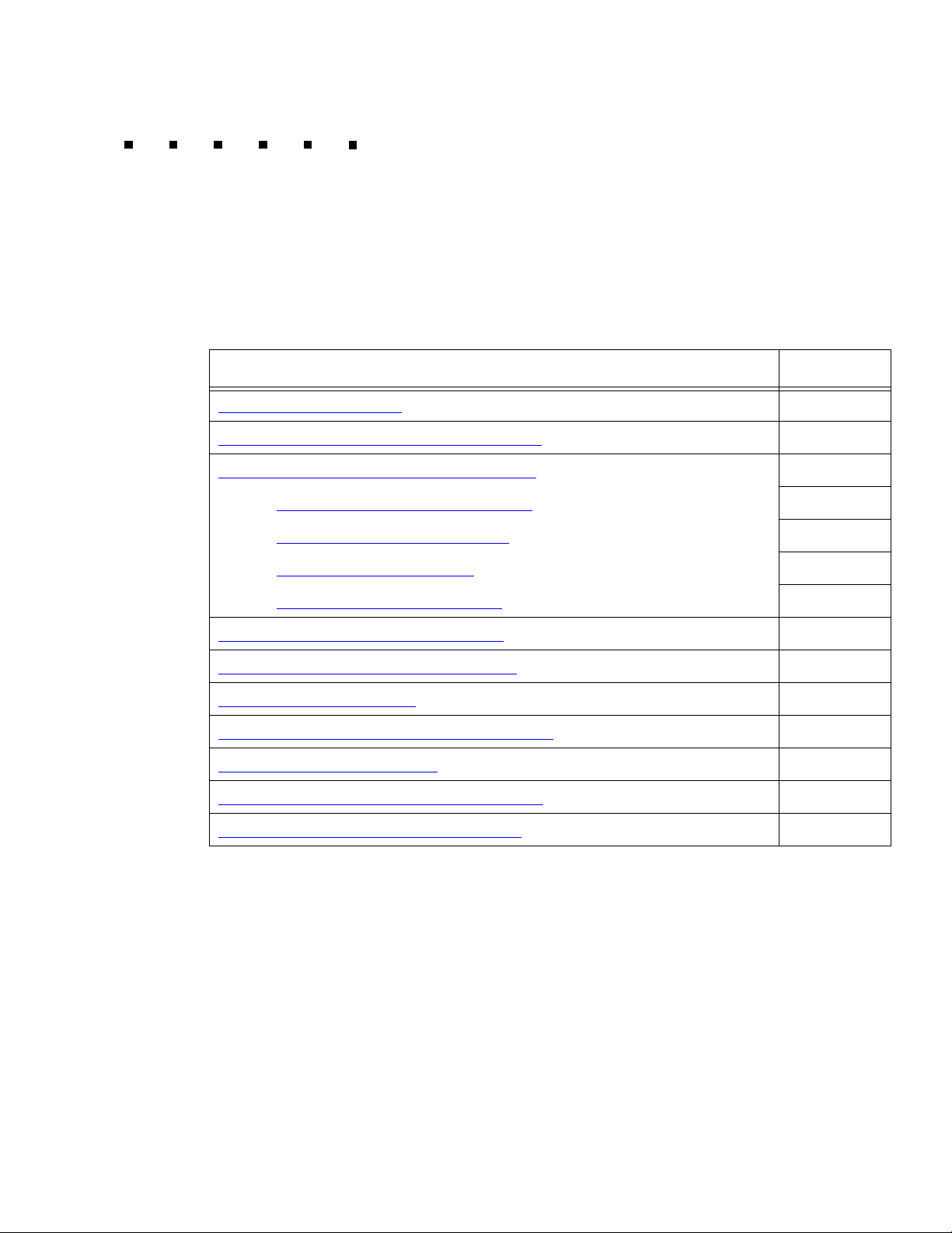
This section describes how to install the Enterprise 3500 computer and related peripheral
equipment. Use the following table to check off each required procedure after completion.
Procedure Completed
Preparing for installation
Unpacking and inventorying the equipment
Assembling the Enterprise 3500 computer
- Installing the fiber-cable organizer
- Connecting the AC power cord
- Fiber channel disk cabling
- Attaching the SCSI terminator
Connecting the monitor and keyboard
Connecting the remote console modem
Connecting the switch link
Powering up the system and verifying POST
Identifying installed I/O cards
Setting the remote console modem options
Turning the system over for provisioning
on page 20
:
on page 30
on page 32
on page 34
on page 39
on page 42
on page 44
on page 45
on page 49
on page 57
on page 24
on page 46
on page 51
Issue 6.0 May 2005 19
Page 20
Installation
Preparing for installation
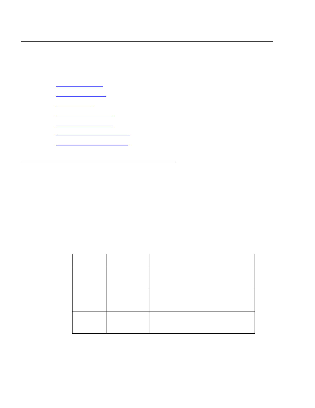
This section contains information that will help you prepare for the Enterprise 3500
computer installation:
● Safety precautions on page 20
● System precautions on page 21
● Required tools on page 21
● Electrical specifications on page 22
● Physical specifications on page 22
● Service access specifications on page 23
● Environmental specifications on page 23
Safety precautions
For your protection, observe the following safety precautions when setting up your
equipment:
● Follow all cautions, warnings, and instructions that are marked on the equipment.
● Never push objects of any kind through openings in the equipment. They could touch
dangerous voltage points or short out components that could result in fire or electric
shock.
● Refer servicing of equipment to qualified personnel.
● To protect both yourself and the equipment, observe the following precautions.
Item Problem Precaution
Wrist or
foot strap
ESD Wear a conductive wrist strap or foot
strap when handling printed circuit
boards.
Cover
panels
Board slot
filler
panels
System
damage and
overheating
System
damage and
overheating
Reinstall all cabinet cover panels after
you perform any service work on the
system.
Make sure that a filler panel is installed
on all empty board slots.
20 Avaya CMS Sun Enterprise 3500 Computer Hardware Installation, Maintenance, and Troubleshooting
Page 21

System precautions
Ensure that the voltage and frequency of the power outlet that is used matches the
electrical rating labels on the equipment.
Wear antistatic wrist straps when handling any magnetic storage devices, CPU/Memory+
boards, or other printed circuit boards.
The Enterprise 3500 computer has an autosensing power supply using nominal input
voltages of 100 to 240 V AC at 47 to 63 Hz. The Enterprise 3500 must be powered by a
nonswitched, dedicated, 15-amp circuit. Sun products are designed to work with
single-phase power systems with a grounded neutral conductor. To reduce the risk of
electric shock, do not plug Sun products into another type of power source. Contact your
facilities manager or qualified electrician if you are unsure of what type of power is supplied
to your building.
Each of the following items requires access by way of a separate power cord:
● Enterprise 3500 computer
● External peripherals
Preparing for installation
● Monitor
!
WARNING:
WARNING: DO NOT make mechanical or electrical modifications to the cabinet. Sun
Microsystems is not responsible for regulatory compliance of modified
cabinets.
Required tools
You need the following tools to do the installation:
● Phillips
● Needle-nose pliers
● ESD grounding wrist strap
● Antistatic mat
®
#2 screwdriver
Issue 6.0 May 2005 21
Page 22
Installation
Electrical specifications
Note:
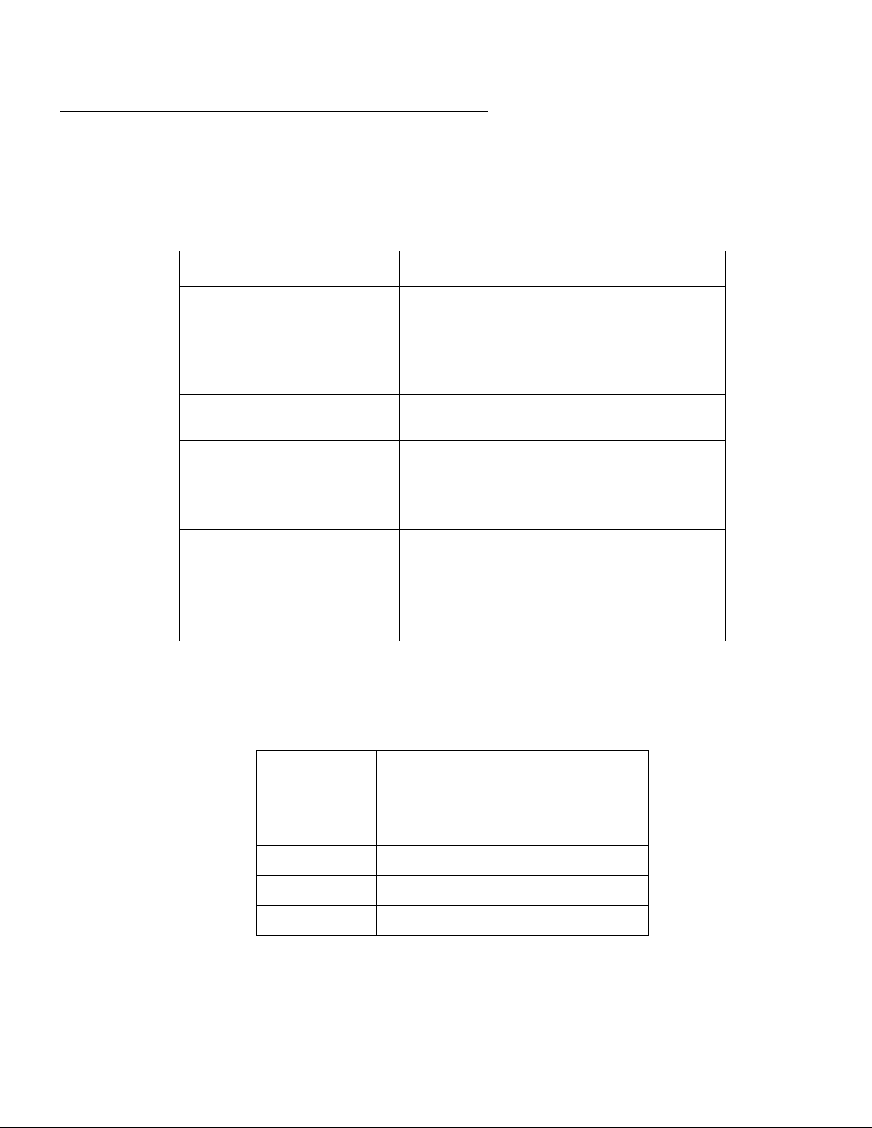
Note: For power integrity, an Uninterruptible Power Supply (UPS) is recommended
for all installations.
Parameter Value
Input current
● Voltage range
● 100-240 V AC, autosensing
● Current, maximum
● Current, frequency range
Input power rating (total
continuous power)
Volt-ampere rating 950 VA
BTU rating 3000 BTU
Power factor 0.92 - 0.96
Wall plug type
● U.S.
● Non-U.S.
CPU plug type IEC 320
Physical specifications
● 9.5A@100 V
● 47-63 Hz
875 W
● NEMA 5-15P
● Power cords must be obtained locally
Parameter English value Metric value
Height 25.5 inches 64.5 centimeters
Width 17 inches 43.2 centimeters
Depth 23.5 inches 59.7 centimeters
Weight 185 pounds 84 kilograms
Power cord 6.0 feet 1.8 meters
22 Avaya CMS Sun Enterprise 3500 Computer Hardware Installation, Maintenance, and Troubleshooting
Page 23
Service access specifications
Parameter English value Metric value
Front 18 inches 45 centimeters
Rear 18 inches 45 centimeters
Left 6 inches 15 centimeters
Right 6 inches 15 centimeters
Environmental specifications
For the most reliable system operation:
● The room must have sufficient air conditioning capacity to support the cooling needs of
the entire system.
Preparing for installation
● The air conditioning system must have controls that prevent excessive temperature
changes.
Follow the guidelines in the table below for temperature, humidity, and altitude limits for
units in operation and for units that are not in operation (that is, units that are in transit or in
storage).
Parameter Operating Nonoperating
Temperature 41°F to 95°F (5°C to 35°C) -4°F to 140°F (-20°C to 60°C)
Humidity
(max)
Altitude (max) 10,000 feet (3 kilometers) 40,000 feet (12 kilometers)
20% to 80% RH
noncondensing
27°C max wb
93% RH
Issue 6.0 May 2005 23
Page 24

Installation
Unpacking and inventorying the equipment
!
WARNING:
WARNING: Never move the system when the power is on. Excessive movement can
cause catastrophic disk drive failure. Always turn the power off before
moving cabinets.
!
WARNING:
WARNING: Always wear an electrostatic discharge (ESD) wrist strap when handling
internal components.
Note:
Note: Always have up-to-date system backups before turning the computer off and
moving the computer.
Unpack the computer and the associated peripheral equipment. Compare the contents of
the carton to the shipping inventory list to verify that all equipment was delivered.
Inspect all shipping cartons for evidence of physical damage. If a shipping carton is
damaged, request that the carrier representative be present before the carton is opened.
In the United States (U.S.), contact the Technical Service Center (TSC) if any computer
parts are defective on arrival. Contact Avaya customer service if any computer parts are
missing.
Outside of the U.S., contact your Avaya representative or distributor if any computer parts
are missing or defective.
As you unpack the system, find the high-speed serial interface (HSI/S) loopback plugs.
The plugs are normally in the box with the HSI/S cables and patch panels. You may need
the plugs for future troubleshooting. For instructions on how to use the loopback plugs on a
CMS computer, see Avaya CMS Switch Connections, Administration, and
Troubleshooting, 585-215-876.
This section includes the following topics:
● Parts list on page 25
● Determining the computer model on page 26
● Computer layout on page 28
● Hardware options on page 29
24 Avaya CMS Sun Enterprise 3500 Computer Hardware Installation, Maintenance, and Troubleshooting
Page 25

Parts list
Verify that you have the following components of the Enterprise 3500 computer:
● Enterprise 3500 cabinet (including installed boards, cards, and disk drives)
● Fiber cable organizer and mounting hardware
● Power cord
● Fiber cables:
● Gigabit interface converter (GBIC) modules:
Unpacking and inventorying the equipment
- One for a CMS nonmirrored system
- Two for a CMS mirrored system
- One or two for an Explorer II/NICE Analyzer system
- Two for a CMS nonmirrored system
- Four for a CMS mirrored system
- Two or four for an Explorer II/NICE Analyzer system
● Monitor and power cord
● Monitor cable
● Keyboard and cable
● Mouse and cable
● SCSI terminator (usually located in a plastic bag with the fiber cable)
● For the 4-millimeter DDS4 tape drive:
- One blank DDS4 tape for backups
- One DDS4 tape that contains the Avaya factory configuration CMSADM filesystem
backup
- One DDS4 tape drive cleaning cartridge
● For the 8-millimeter Mammoth tape drive:
- One blank 170-meter, AME Mammoth tape for backups
- One 170-meter AME Mammoth tape that contains the Avaya factory configuration
CMSADM filesystem backup
- One Exabyte 8-millimeter Mammoth tape drive cleaning cartridge
Issue 6.0 May 2005 25
Page 26

Installation
Determining the computer model
This book is written for use with several different models of the Enterprise 3500 computer.
The differences between the models are few. This section shows how to identify the
different models.
Features
Each of the different models have distinctive features that will also assist you in
determining what model you have.
● Model 3500
- SBus+ I/O board with a Turbo GX video card
- 7200 RPM, 9.1-GB, 1.6-inch wide disk drives
● Model 3501
- New Clock+ board (supports faster processors)
- Graphics+ I/O board with a Creator video card
- 10000 RPM, 9.1-GB, 1-inch wide disk drives
● Model 3503
- 1-GB memory (minimum)
- 18-GB or larger disk drives
-DVD-ROM drive
- On older models, the 8-millimeter Exabyte tape drive is used. On newer models,
the 4-millimeter DDS4 tape drive is used.
- Newer models have CPUs with a 400 or 500 MHz clock
Physical labeling
All models are labeled as Enterprise 3500.
26 Avaya CMS Sun Enterprise 3500 Computer Hardware Installation, Maintenance, and Troubleshooting
Page 27

Software check
To determine the model of the computer once the computer is operational:
1. Log in as root.
2. Enter the following commands to determine if the computer has a Turbo GX video card
(3500) or a Creator video card (3501/3503):
grep cgsix /etc/path_to_inst
grep ffb /etc/path_to_inst
● If the computer is a Model 3500, the following message is displayed:
● If the computer is a Model 3501 or 3503, the following message is displayed:
Unpacking and inventorying the equipment
“/sbus@3,0/cgsix@0” 0 “cgsix”
“/SUNW,ffb@2,0” 0 “ffb”
Issue 6.0 May 2005 27
Page 28
Installation
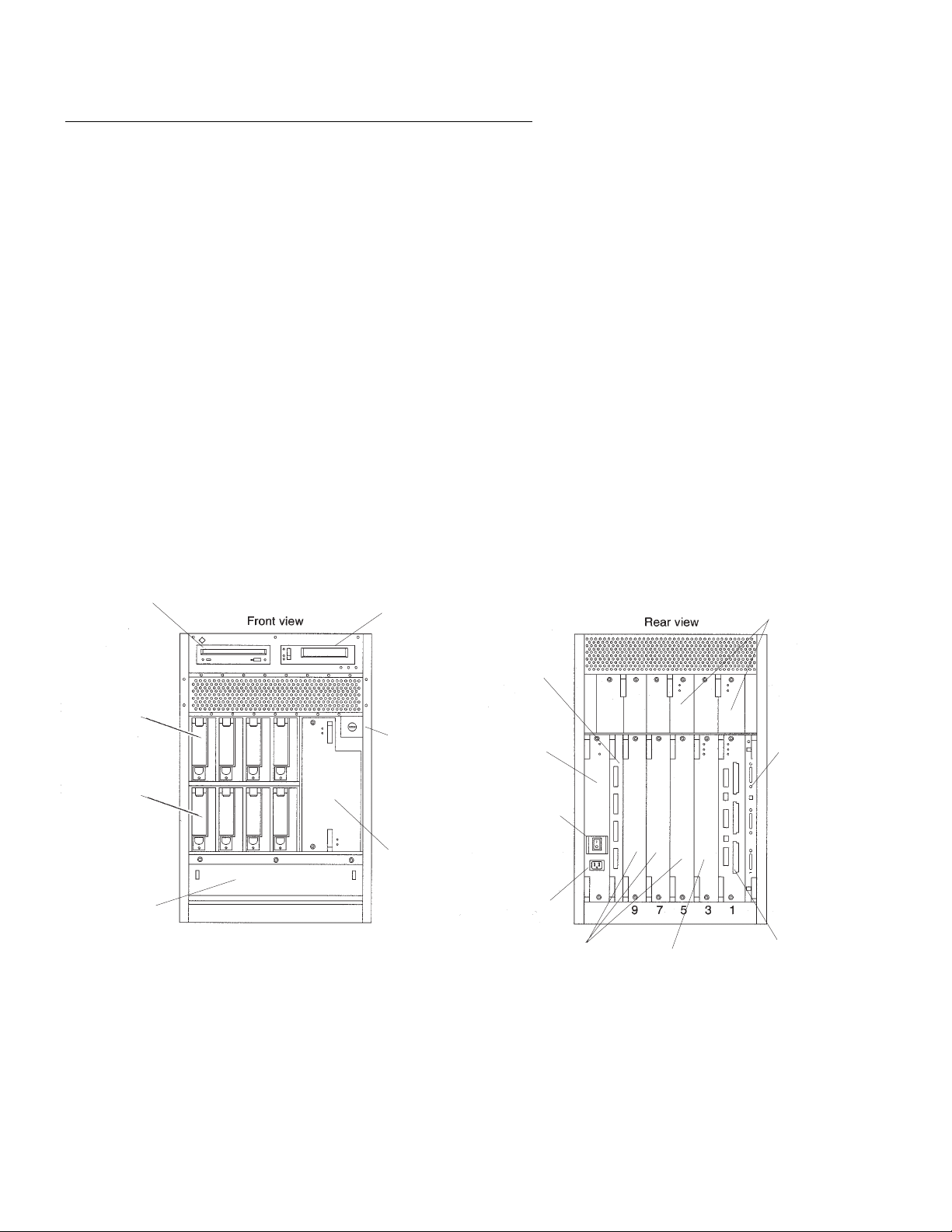
Computer layout
Familiarize yourself with the layout of the Enterprise 3500. The minimum configuration for
the computer is as follows:
● One power/cooling module (PCMs) and two PCM filler panels
● Fan tray
● One Clock+ board
● One CPU/Memory+ board (with two UltraSPARC ll CPU modules and memory modules)
● One I/O board, either a Graphics+ I/O board or an SBus+ I/O board
● One Fiber Channel-Arbitrated Loop (FC-AL) interface board
● One disk drive (nonmirrored, in slot 0); two disk drives (mirrored, in slots 0 and 4)
● Filler panels for any unpopulated board slots
● One peripheral power supply (PPS) with an AC power sequencer
● One auxiliary PPS or one thermal protection module (TPM)
CD-ROM or
DVD-ROM
Disk
drives
(mirrored)
Disk
drives
(mirrored and
nonmirrored)
Fan tray
3500_cab.cdr
● Media tray for removable media, including CD-ROM or DVD-ROM drive and tape drive
Tape
drive
Power cooling
modules (PCM)
FC-AL interface
board
Key
switch
7654
Peripheral
power supply
(PPS)
Clock+
board
AC power
0123
Auxiliary peripheral
power supply
switch
or
thermal protection
module
AC
connector
Filler
panels
CPU/Memory+
board
I/O board
(Graphics+
or SBus+)
28 Avaya CMS Sun Enterprise 3500 Computer Hardware Installation, Maintenance, and Troubleshooting
Page 29

Hardware options
The following table lists the hardware options for the Enterprise 3500 computer.
.
Unpacking and inventorying the equipment
Option Maximum
Comments
Quantity
CPU/Memory+
board and I/O
boards
5 total per system Each slot can accept a CPU/Memory+ or I/O
board (Graphics+ or SBus+). Combinations can
vary. Since slot 1 connects to the onboard SCSI
devices, this slot should be reserved for the first
I/O board. One system board becomes the
system master automatically. Jumper changes
are not needed.
UltraSPARC ll
CPU modules
8 per system There may be 0, 1, or 2 modules on each CPU/
Memory+ board. The first CPU/Memory+ board
has 2 modules.
Memory
modules
0, 8, or 16 SIMMs
per CPU/Memory+
board
SIMM sizes are 32 or 128 MBytes. Do not mix
sizes within the same bank. Add 8 SIMMs at a
time. Install SIMMs in all bank 0 sockets first on
each CPU/Memory+ board, from the lowest slot
to the highest. Once bank 0 is full, install the
remaining SIMMs in bank 1 sockets in the same
order.
SBus cards 6 per system There may be up to 3 cards per SBus+ I/O
board, or up to 2 cards per Graphics+ I/O board.
Media tray CD-ROM or
DVD-ROM drive
and tape drive
The media tray holds removable-media drives
only. One CD-ROM drive or one DVD-ROM
drive, and one tape drive is standard equipment.
On older models, the 8-millimeter Exabyte tape
drive is used. On newer models, the 4-millimeter
DDS4 tape drive is used.
FC-AL interface
1 per system The FC-AL interface board has one or two GBIC
board
Disk drives For CMS, 4 disks
maximum in a
nonmirrored
system and 8 disks
maximum in a
mirrored system
For Explorer II or
NICE Analyzer, 8
disks maximum
modules installed.
Each bank can hold 4 disk drives. For a
nonmirrored CMS system, install disks in the
bottom bank only from left to right, starting with
slot 0. Install disks in the top bank from left to
right only when using disk mirroring (CMS) or
Explorer II/NICE Analyzer.
NOTE: Slot 0 is reserved for the boot disk in all
systems, and slot 4 is reserved for the mirror
boot disk for CMS.
Issue 6.0 May 2005 29
Page 30

Installation
Assembling the Enterprise 3500 computer
The following section describes how you assemble the different parts of the
Enterprise 3500 computer, including the following:
● Installing the fiber-cable organizer on page 30
● Connecting the AC power cord on page 32
● Fiber channel disk cabling on page 34
● Attaching the SCSI terminator on page 39
Installing the fiber-cable organizer
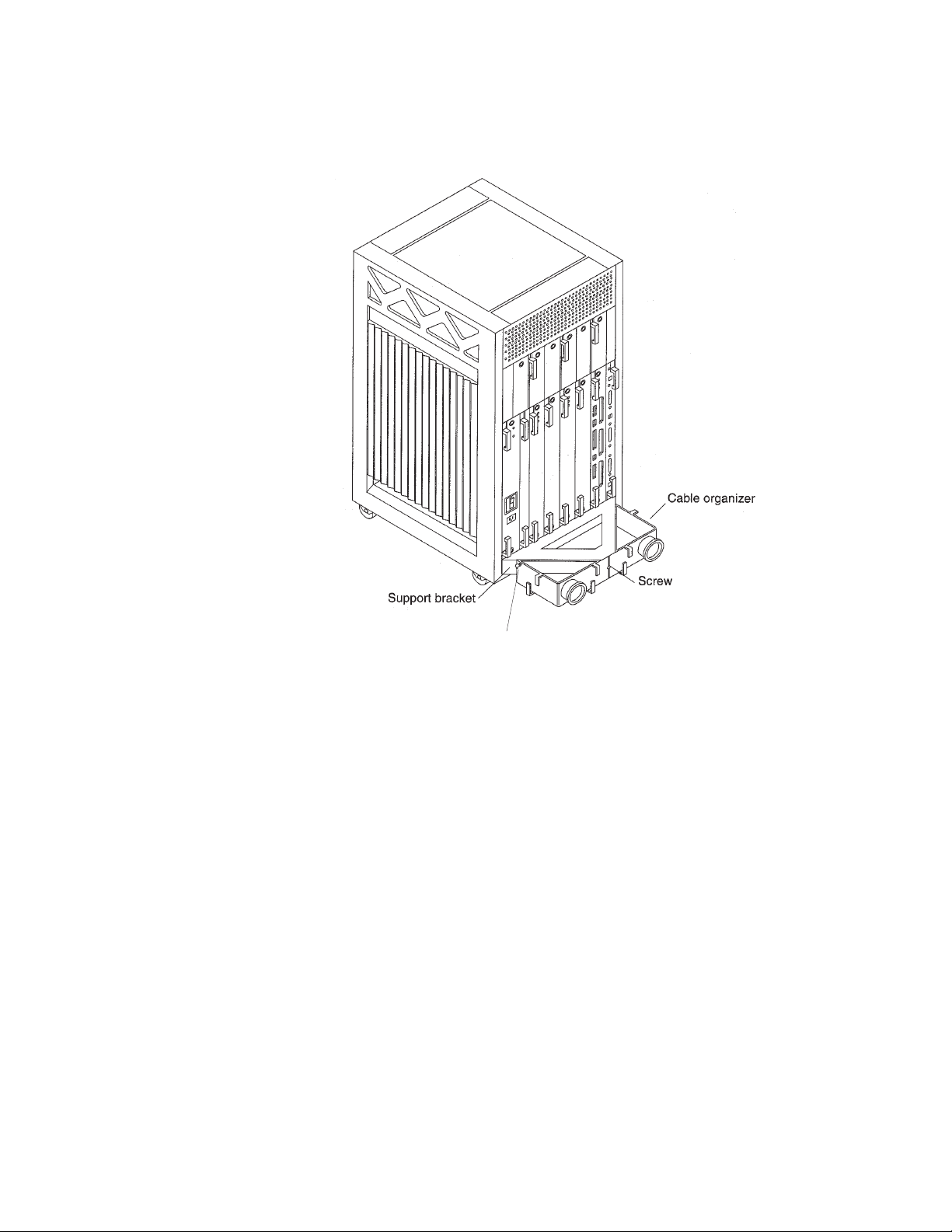
Use the fiber-cable organizer to route the 2-meter fiber-optic cables to connect the FC-AL
interface board and the I/O board. The cable organizer can prevent damage to the
fiber-optic cable by ensuring that the 1.0-inch minimum bend radius rule is observed. The
30 Avaya CMS Sun Enterprise 3500 Computer Hardware Installation, Maintenance, and Troubleshooting
Page 31
Assembling the Enterprise 3500 computer
fiber cable organizer kit includes two organizer sections and one screw. See the following
figure.
Power cord
retainer clip
organizer1.cdr
To install the cable organizer:
1. Remove the screw that secures the power cord retainer clip to the support bracket at
the rear of the system.
2. Position one of the fiber cable organizer sections with the spool facing toward you. Set
the hooks on the back of the organizer into the corresponding cutouts on the right side
of the support bracket.
The top of the brace should be flush with the top of the support bracket. The organizer
extends below the bracket.
3. Secure the organizer by pushing it outward along the support bracket until the snap at
the rear of the organizer clicks audibly into place.
4. Install the other spool brace by repeating Steps 2 and 3.
5. Using the screw that is included in the kit, fasten the spool braces to the support
bracket through the center-front cutout that is formed when both braces are in place.
6. Remount the retainer clip through the hex nut at the notch on the side of the organizer.
7. Set the retainer clip screw into the hex nut.
Issue 6.0 May 2005 31
Page 32
Installation
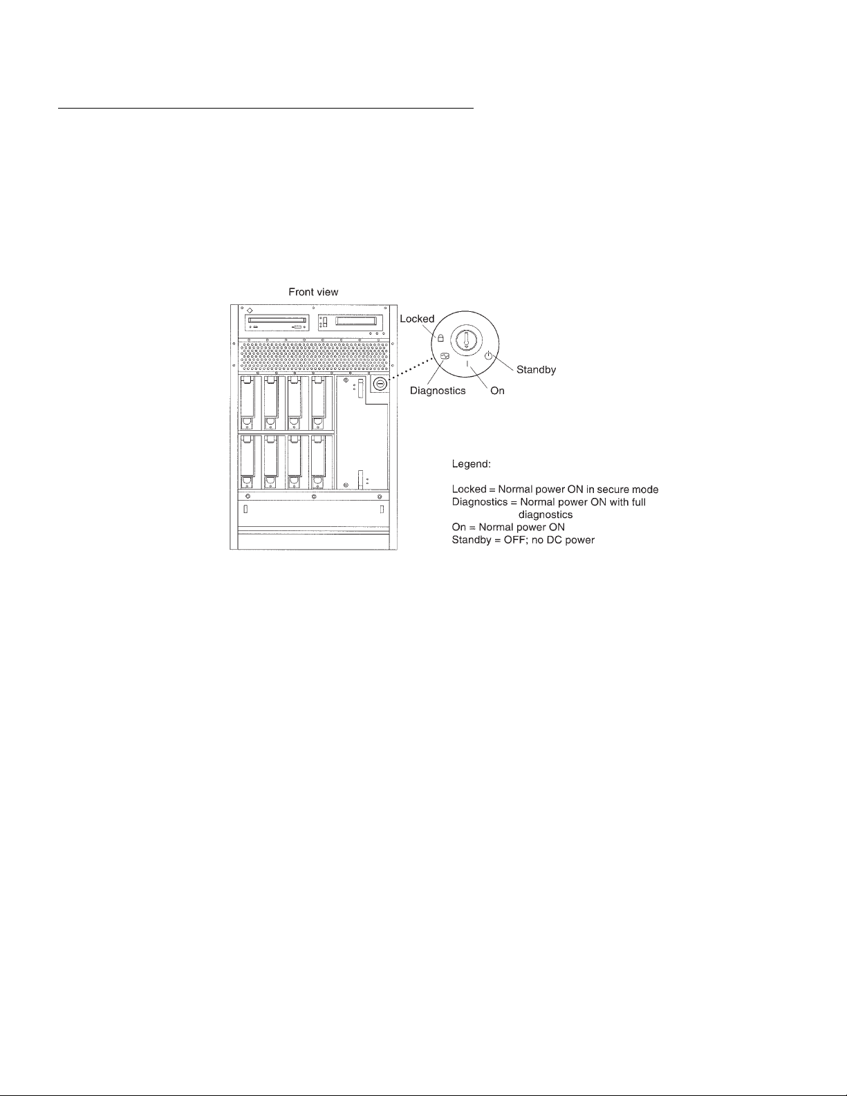
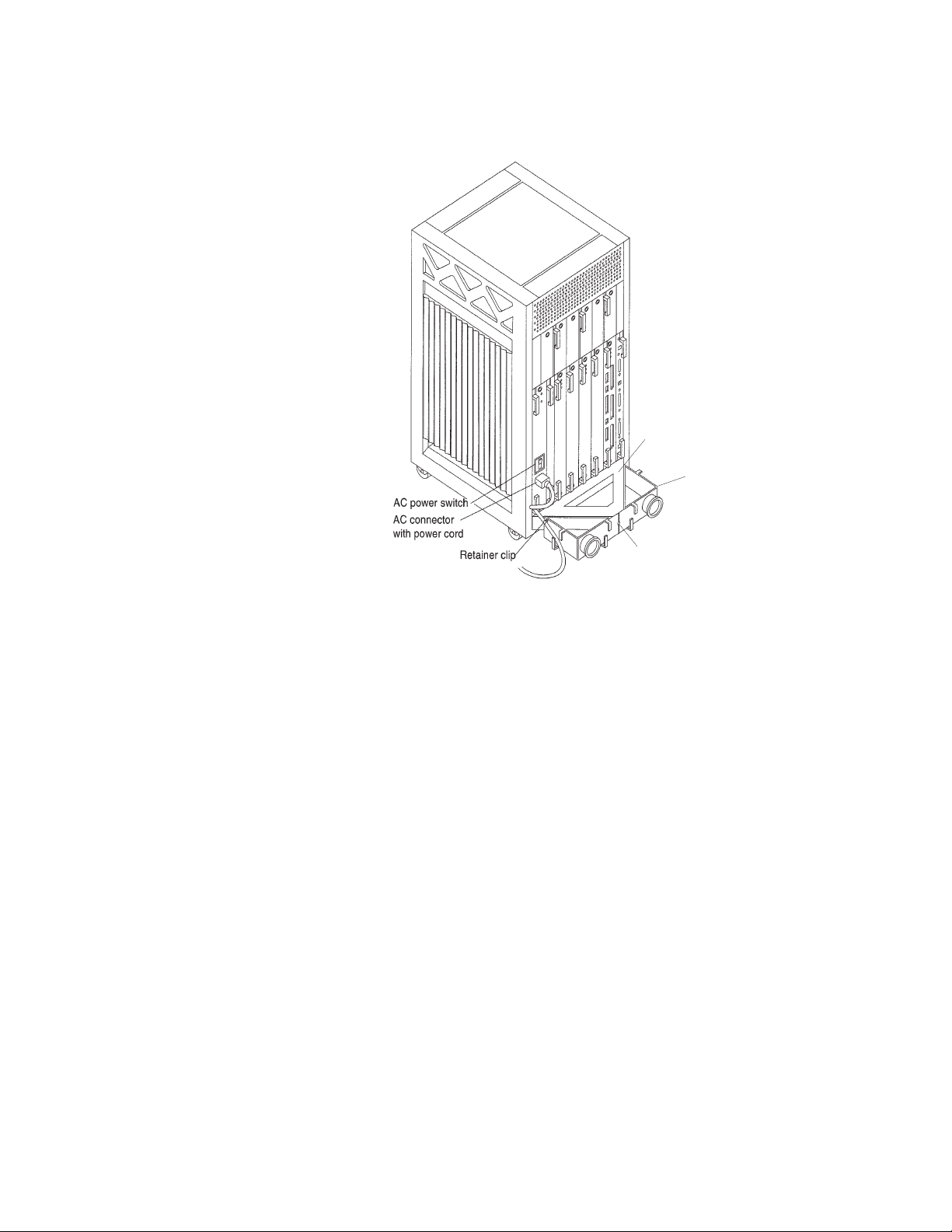
Connecting the AC power cord
To connect the AC power cord:
1. Unlock and open the front door of the computer.
2. Locate the key switch in the upper-right corner, insert the key, and turn the key switch
to the standby position.
key_switch.cdr
32 Avaya CMS Sun Enterprise 3500 Computer Hardware Installation, Maintenance, and Troubleshooting
Page 33
Assembling the Enterprise 3500 computer
3. Turn off the AC power switch on the back of the computer.
Support
bracket
Cable
organizer
Screw
power.cdr
4. Connect the IEC 320 end of the power cord to the AC connector.
For installations outside of the U.S. and Canada, obtain a power cord for your local
configuration.
5. Route the power cord through the power cord retainer clip on the cable organizer.
6. Plug the power cord from the computer into an outlet on the UPS.
A UPS provides a temporary electrical supply to a computer for several minutes,
depending on the number of components connected to the UPS. For a CMS computer,
a 2KVA minimum UPS is required for all installations. See your UPS documentation to
determine the projected amount of backup battery time for your model. If the system is
without power for longer than the backup time, the system may shut down improperly,
and the customer could lose data.
If a UPS is not being used, you must use a grounded outlet on a dedicated 15-amp
circuit.
Issue 6.0 May 2005 33
Page 34
Installation
Fiber channel disk cabling
!
WARNING:
WARNING: The plastic dust caps that are on the ends of the fiber cables must remain
intact until you are ready to install the cables. Ensure that you observe the
fiber-optic cable minimum bend radius rule when you handle the cables.
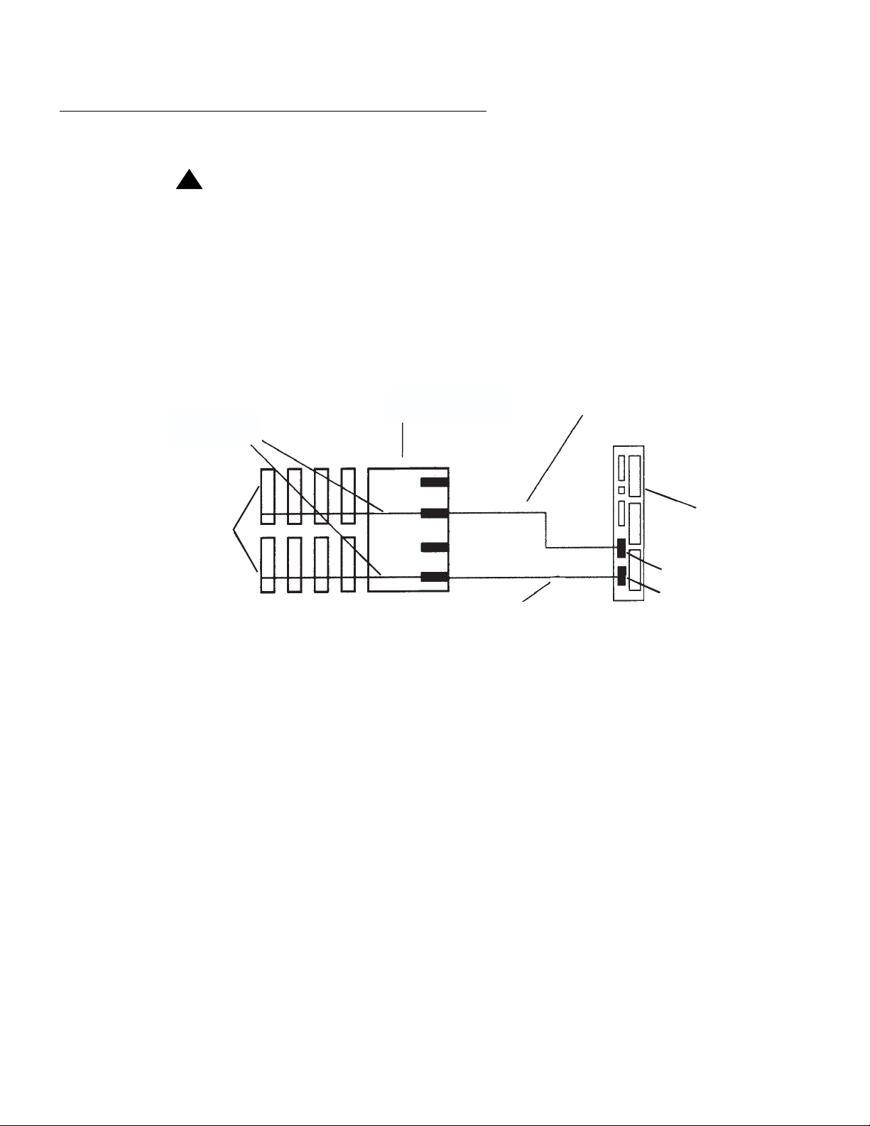
The following figure shows the overall fiber channel cable connectivity between the FC-AL
interface board and an I/O board. Use this figure when installing the fiber channel cables.
For a CMS nonmirrored system, you install only the lower cable. For a CMS mirrored
system, or an Explorer II/NICE Analyzer system with more than four disk drives, you install
both cables.
FC-AL interface
to disk drives
FC-AL interface board
FC-AL loop to upper bank
(mirrored CMS, or Explorer II system
with more than 4 disks)
Up to four FC-AL
disk drives per bank
0-3 (nonmirrored CMS)
4-7 (mirrored CMS)
0-7 (Explorer II)
5
4
01
UB
7
6
3
2
GBIC 1
GBIC 0
UA
LB
LA
FC-AL loop to lower bank
(all systems)
I/O board
in slot 1
(Graphics+
or Sbus+)
GBIC 1
GBIC 0
diskmirror.cdr
34 Avaya CMS Sun Enterprise 3500 Computer Hardware Installation, Maintenance, and Troubleshooting
Page 35
Assembling the Enterprise 3500 computer
Connecting the fiber cable to the FC-AL interface board
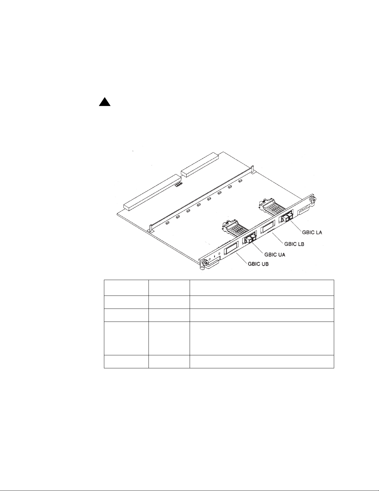
Internal FC-AL disk drives require an interface board to communicate to an I/O board. This
figure identifies the GBIC modules on the FC-AL interface board, and the table identifies
the GBIC that is associated with each disk drive. The GBIC modules are preinstalled at the
factory. Only GBIC modules in positions LA and UA are used.
!
WARNING:
WARNING: The plastic dust caps that are on the ends of the fiber cables must remain
intact until you are ready to install the cables. Ensure that you observe the
fiber-optic cable minimum bend radius rule when you handle the cables.
(Top)
interfaceboard.cdr
Disk drives Drive port GBIC name and location
1
0
, 1, 2, 3
A GBIC LA (lower bank); default for all systems
N/A B GBIC LB (lower bank); not used
2
, 5, 6, 7
4
A GBIC UA (upper bank); used for CMS
mirrored systems, or Explorer II/NICE
Analyzer systems with more than four disk
drives
N/A B GBIC UB (upper bank); not used
1. Disk slot 0 must be reserved for the boot disk on all systems.
2. Disk slot 4 must be reserved for the mirror boot disk with CMS.
Issue 6.0 May 2005 35
Page 36
Installation
Wrapping the fiber cable on the organizer
Use the fiber-cable organizer to route the 2-meter fiber-optic cables to connect the FC-AL
interface board and the I/O board. The cable organizer can prevent damage to the
fiber-optic cable by ensuring that the 1.0-inch minimum bend radius rule is observed. On a
CMS mirrored system, or an Explorer II/NICE Analyzer system with more than four disk
drives, you will install two fiber cables.
!
WARNING:
WARNING: The plastic dust caps that are on the ends of the fiber cables must remain
intact until you are ready to install the cables. Ensure that you observe the
fiber-optic cable minimum bend radius rule when you handle the cables.
To wrap the fiber cable:
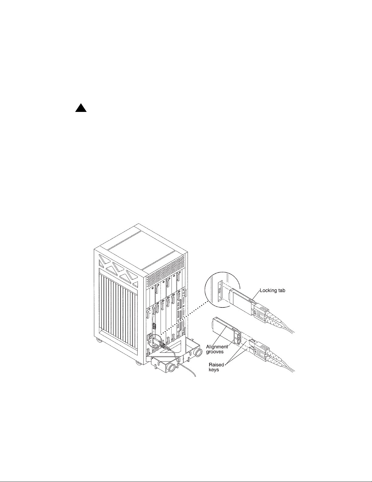
1. Remove the two plastic caps that cover the cable connector on the GBIC modules. The
GBIC modules are preinstalled at the factory.
2. Remove the plastic cap that covers one end of the fiber cable.
3. Connect that end of the fiber cable into the GBIC module that is installed on the FC-AL
interface board.
fiber_ib.cdr
36 Avaya CMS Sun Enterprise 3500 Computer Hardware Installation, Maintenance, and Troubleshooting
Page 37
Assembling the Enterprise 3500 computer
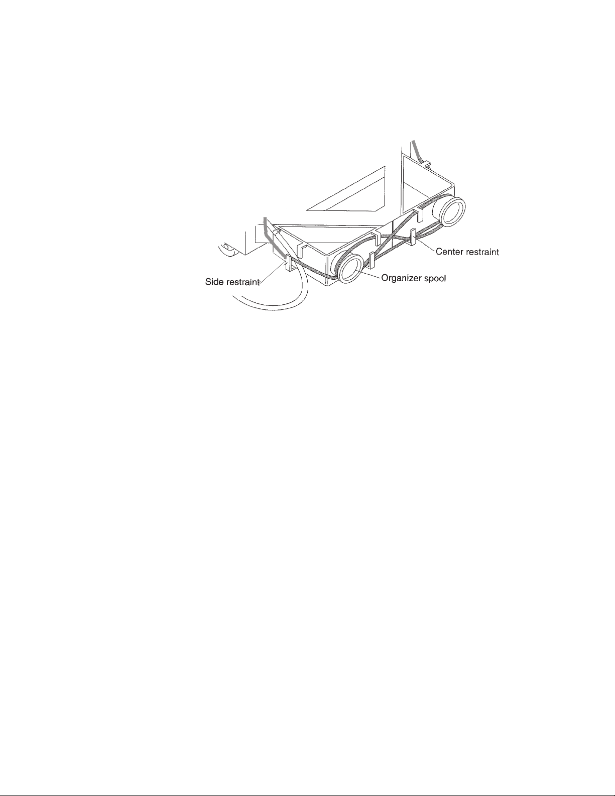
4. Route the fiber cable down toward the bottom of the system, placing it through the left
side restraints on the organizer.
wrapping.cdr
5. Using a “figure 8” pattern, wrap the cable around the bottom of the left spool, then up
and around the right spool threading the cable through the center restraints on the
organizer.
6. Repeat Step 5 until the cable ends up on the right side with enough cable to reach the
I/O board. Thread the cable through the right side restraints and connect it to the I/O
board as described in the next section.
Issue 6.0 May 2005 37
Page 38
Installation
Connecting the fiber cable to the I/O board
To connect the fiber cable to the I/O board:
!
WARNING:
WARNING: The plastic dust caps that are on the ends of the fiber cables must remain
intact until you are ready to install the cables. Ensure that you observe the
fiber-optic cable minimum bend radius rule when you handle the cables.
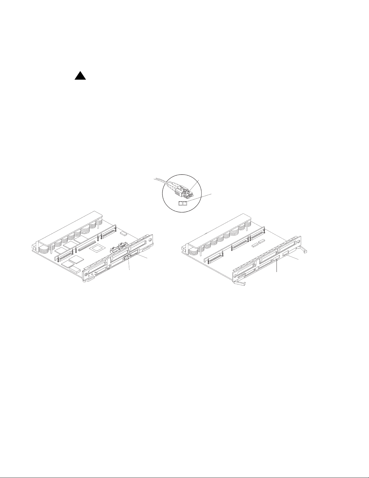
1. Remove the two plastic caps that cover the cable connector on the GBIC module.
2. Remove the plastic cap that covers the other end of the fiber cable.
3. Connect that end of the fiber cable into the GBIC module that is installed on the I/O
board. Align the notch in the cable connector with the key notch in the module
connector.
Notch on fiber cable
Key notch in module connector
(Top)
Graphics+ I/O board
GBIC 0
(all systems)
(mirrored CMS systems or
GBIC 1
Explorer II with more
than four disks)
(Top)
SBus+ I/O board
(all systems)
(mirrored CMS systems or
GBIC 1
Explorer II with more
than four disks)
GBIC 0
gbic_io.cdr
38 Avaya CMS Sun Enterprise 3500 Computer Hardware Installation, Maintenance, and Troubleshooting
Page 39
Attaching the SCSI terminator
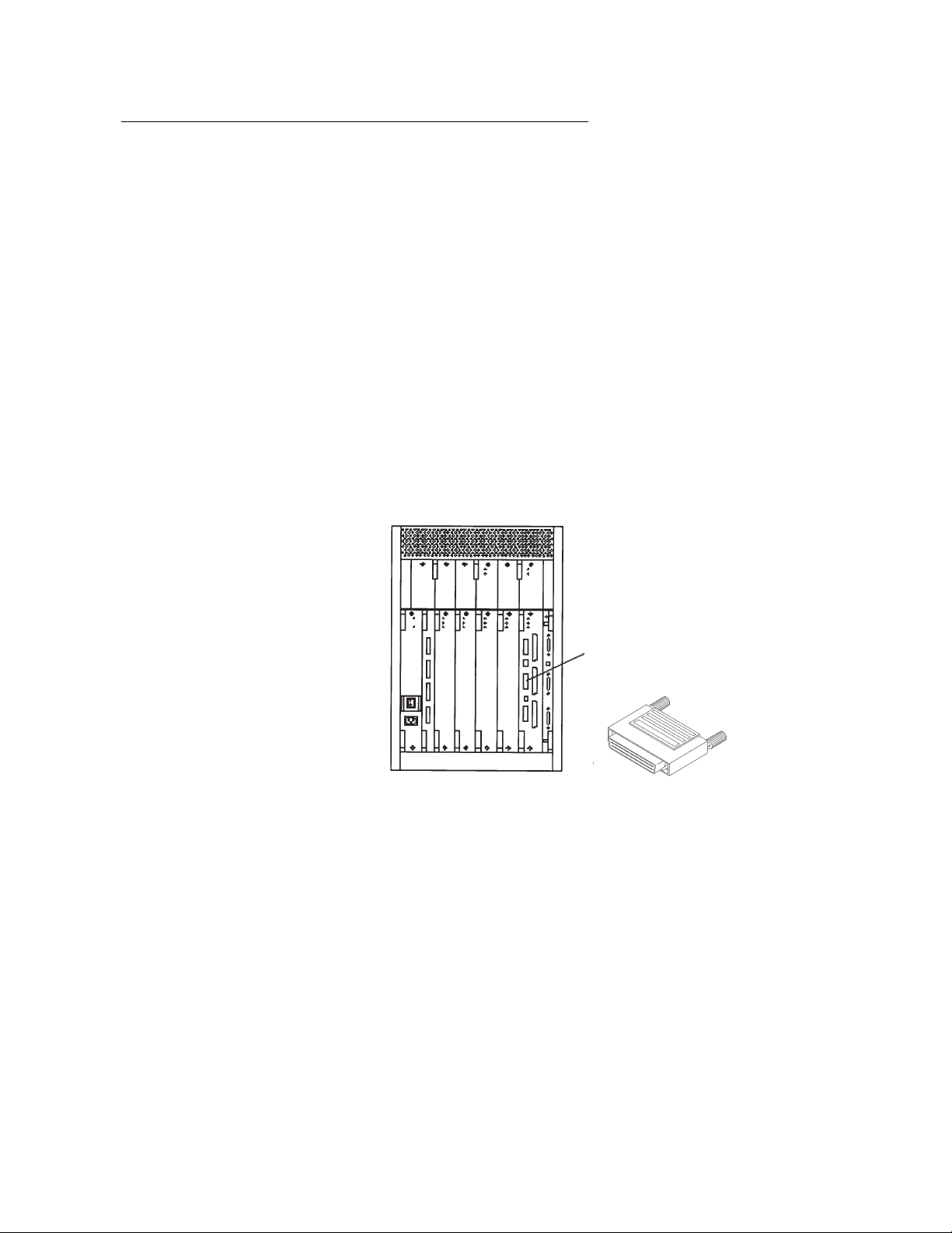
The built-in SCSI connector on the I/O board in slot 1 of any Enterprise 3500 computer
must be terminated if not used for another purpose. This SCSI bus connects to the internal
CD-ROM or DVD-ROM drive and the internal tape drive. The SCSI bus on an I/O board in
any other slot must be terminated only if SCSI devices are connected to that board. A
SCSI port can be used to connect an external tape drive for data migration.
Note:
Note: The SCSI terminator is packaged in a plastic bag with the fiber channel
cable.
To connect the SCSI terminator:
1. Remove the SCSI terminator from the packaging.
2. Attach the SCSI terminator to the SCSI connector on the first I/O board. See the
following figure.
Assembling the Enterprise 3500 computer
terminator.cdr
3. Tighten the screws on the SCSI terminator.
Fast/Wide onboard
SCSI-2 68-pin
connector
68-pin SCSI terminator
Issue 6.0 May 2005 39
Page 40
Installation
Peripheral connectivity and parts list
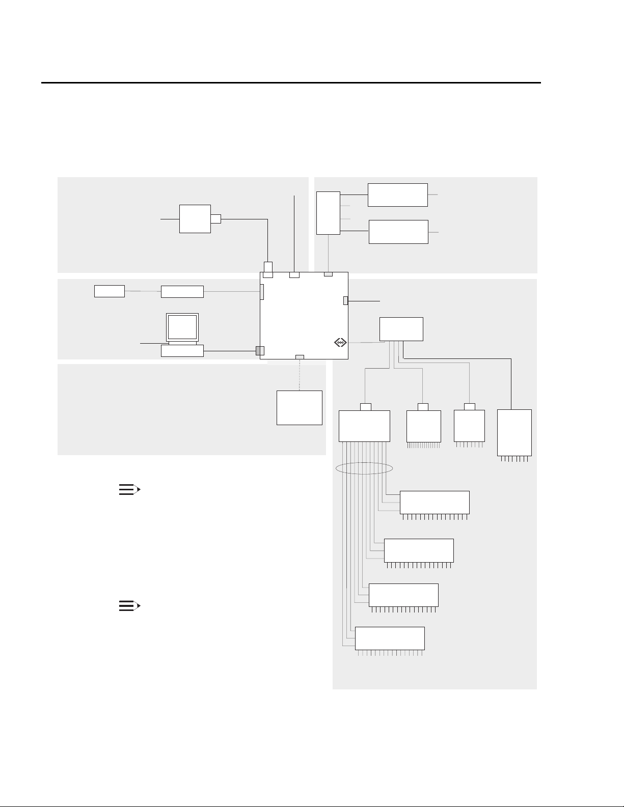
The following diagram shows in general how equipment is connected to the
Enterprise 3500 computer.
Remote console
Telephone line
maintenance center
System Console
Mouse
System console
External drives
T
S
to remote
Modem
Keyboard
F
G
Monitor
R
AB
D
E
NOTE 1:
The Network Hub may be replaced by the
customer's own LAN providing that the
following two conditions are met:
- Any routers or repeaters between the
Sun Enterprise 3500 and the NTS(s)
allow the bootp protocol to pass through.
- The Sun Enterprise 3500 System is
connected to the LAN.
NOTE 2:
Disk
mirroring is available. However, it is not
shown in this diagram because all disks are
internal to the system.
Serial port B
(not used)
Q
B
A
Clock+
board
Enterprise 3500
Computer
Graphics+ I/O or
C
SBus+ I/O board
External SCSI
tape drive
for data
migration only
Sun
L
M
M
K
J
H
TP
I
Black Box
RS-449 - RS-232
interface converter
Black Box
RS-449 - RS-232
interface converter
An HSI/S card is used
for up to four ACDs.
A second HSI/S card
is needed for eight ACDs.
For detailed switch link connectivity, see
CMS Switch Connections, Administration,
and Troubleshooting, 585-215-876
Ethernet port for switch link, R7 and later
(supports up to eight ACDs)
Network
O
hub
See Note 1
N
P
64-port
NTS
NTS patch panel
(16 RS-232 Ports)
NTS patch panel
(16 RS-232 Ports)
NTS patch panel
(16 RS-232 Ports)
For detailed network hub and NTS
connectivity, see CMS Terminals,
Printers, and Modems, 585-215-874
NN
P
16-port
NTS
To terminals,
printers,
modems
NTS patch panel
(16 RS-232 Ports)
X.25 switch links
N
P
8-port
NTS
To terminals,
printers,
modems
Ethernet links
N
8-port
NTS
no parallel
port
To terminals,
printers,
modems
To terminals,
printers,
modems
ultconp.cdr
40 Avaya CMS Sun Enterprise 3500 Computer Hardware Installation, Maintenance, and Troubleshooting
Page 41
Peripheral connectivity and parts list
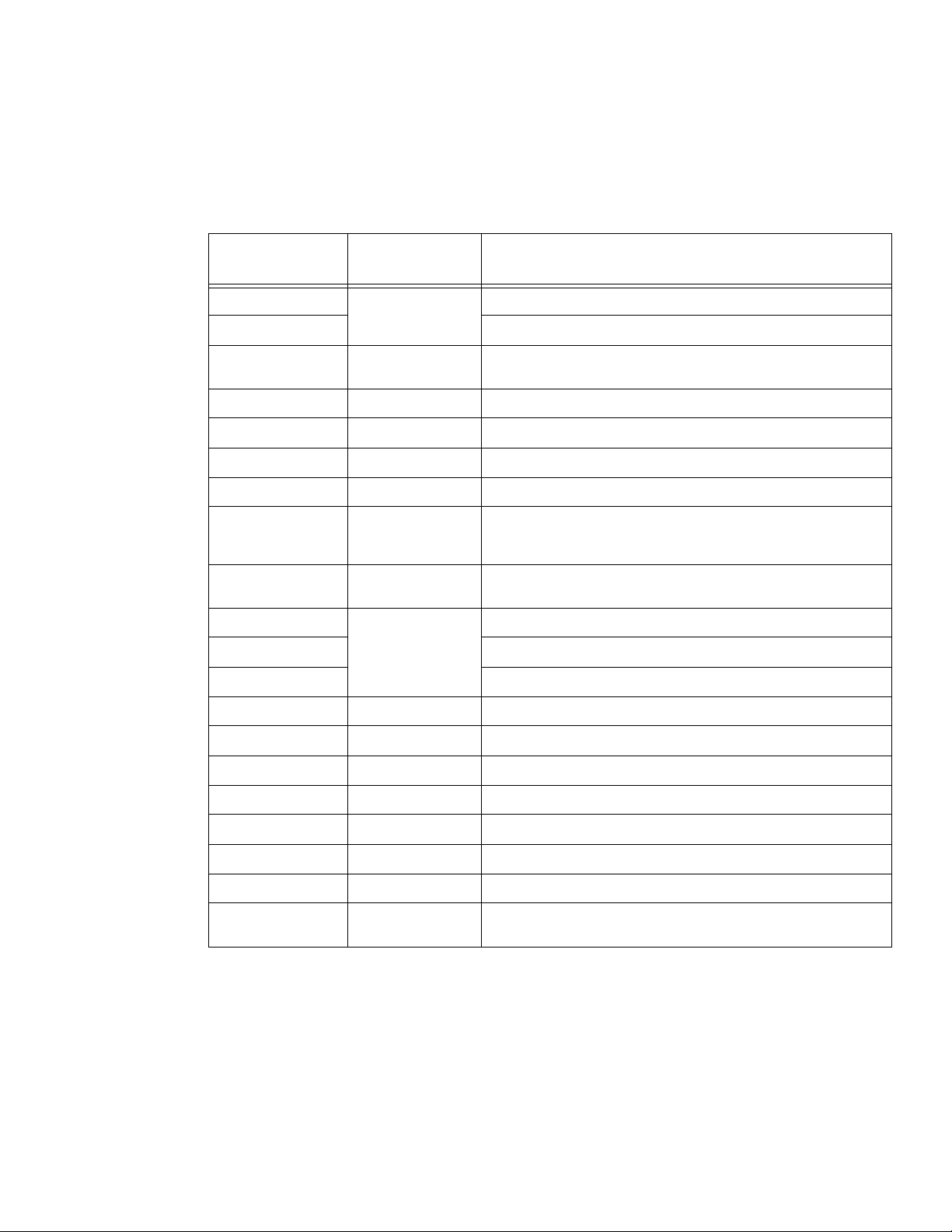
The following table lists the parts that are required to connect most of the external devices
to the Enterprise 3500 computer. For information about connecting terminals, printers, and
modems to the Enterprise 3500 computer, see Avaya CMS Terminals, Printers, and
Modems, 585-215-874. For information about switch connections for CMS, see Avaya
CMS Switch Connections, Administration, and Troubleshooting, 585-215-876.
Connectivity
diagram call out
1
A
1
B
1
C
1
D
1
E
1
F
1
G
1
H
1
I
1
J
1
K
1
L
Comcode, or part
of comcode
2
N/A
Keyboard with cable
Mouse with cable
2
N/A
Creator video card (Graphics+ I/O card slot 1), or
Turbo GX+ video card (SBus+ I/O card slot 0)
2
N/A
N/A
N/A
N/A
2
2
2
13W3 9-pin to 25-pin adapter
Monitor cable
Monitor
Monitor AC power cord
Varies FSBE SBus SCSI/Ethernet card, or
SunFastEthernet 10/100 Mbps ethernet card, or
SunSwift 10/100 Mbps ethernet card
407579986
407934470
SCSI cable, 50-pin to 68-pin, or
SCSI cable, 68-pin to 68-pin
408128239 HSI/S card
HSI/S cable (10 feet, 3 meters)
HSI/S patch panel
Description
M 407086818 RS-449 cable (10 feet, 3 meters)
N 407086826 Category 5 UTP cable (10 feet, 3 meters)
O 407086735 CentreCOM LAN hub
P 407086859 CentreCOM transceiver
Q 846362754 DB25-to-RJ45 ACU modem adapter
R 846983039 10-wire modular cord (10 feet, 3 meters)
S 846362770 RJ45-to-DB25 remote console adapter
T 407633999
Vari es
Sportster Model 839 33.6 remote console modem
Comsphere 3910 remote console modem
1. Sun Microsystems provides maintenance sparing for these parts.
2. The comcode for this bundle changes regularly and may not be ordered for maintenance spares,
so it is not listed in the table. This bundle includes the processor, peripherals, and other equipment.
Issue 6.0 May 2005 41
Page 42
Installation
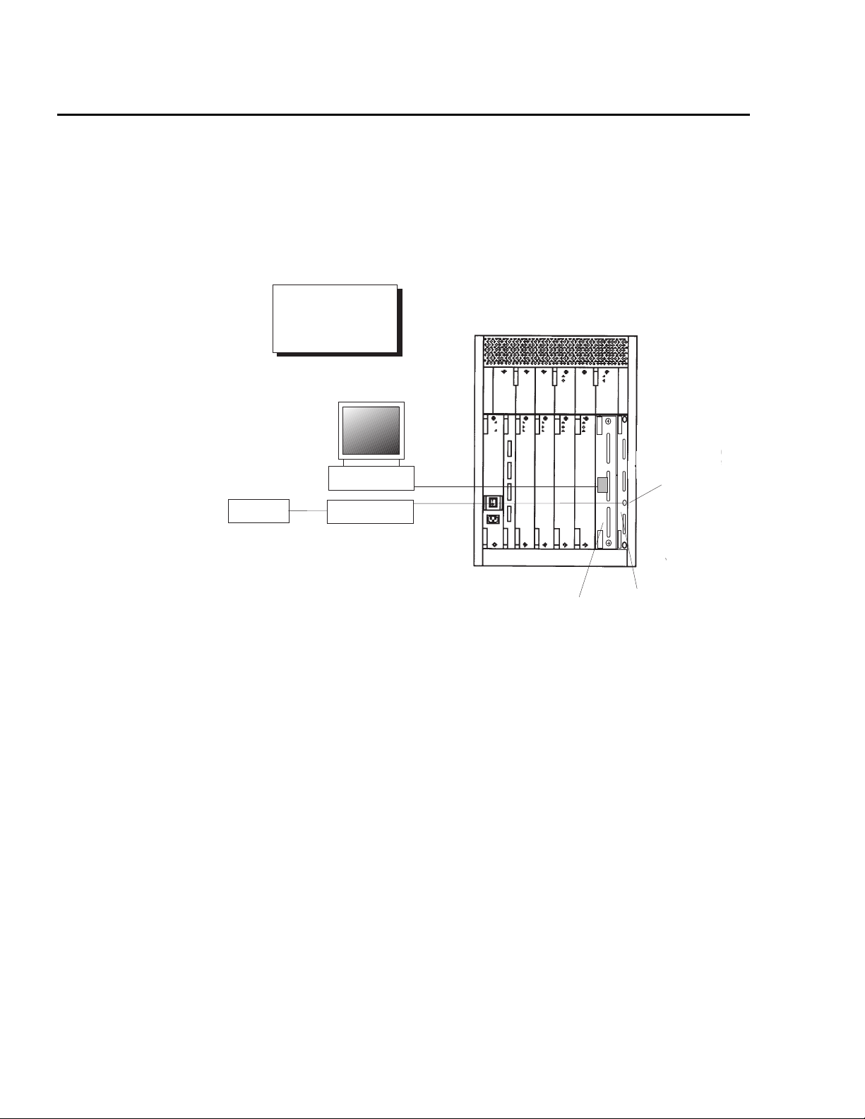
Connecting the monitor and keyboard
The keyboard connects to the Clock+ board. The monitor connects to either the first SBus+
I/O board or the Graphics+ I/O board.
The following figure shows how to connect the monitor and keyboard to the
Enterprise 3500 computer using the Graphics+ I/O board in slot 1.
Key:
A = Keyboard cable
B = Mouse and cable
C = Creator graphics card
D = 13W3 adapter
E = Monitor cable
0
Mouse
mon_graphics.cdr
Monitor
B
Keyboard
E
A
Graphics+ I/O
board in slot 1
C
A
D
1
2
B
Keyboard
connector
Clock+
board
42 Avaya CMS Sun Enterprise 3500 Computer Hardware Installation, Maintenance, and Troubleshooting
Page 43
Connecting the monitor and keyboard
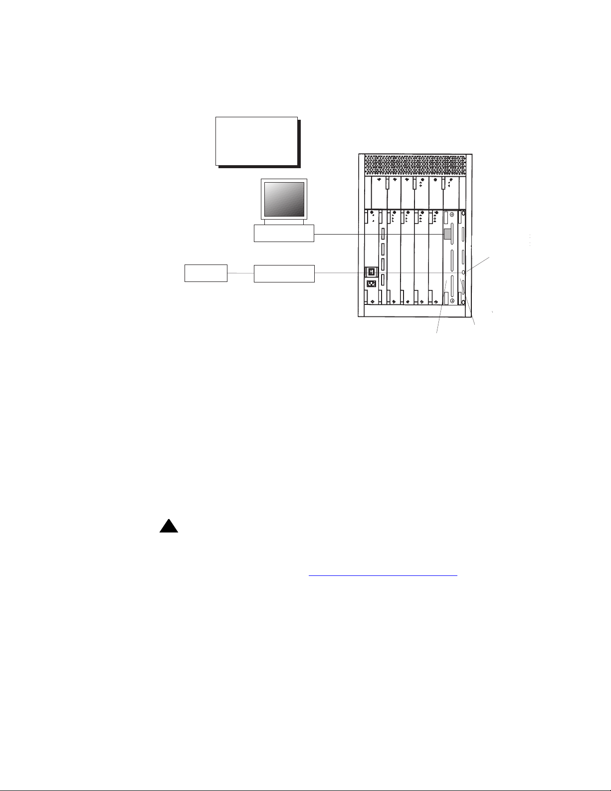
The following figure shows how to connect the monitor and keyboard to the
Enterprise 3500 computer using the SBus+ I/O board in slot 1.
Key:
A = Keyboard cable
B = Mouse and cable
C = Turbo GX+ card
D = 13W3 adapter
E = Monitor cable
Mouse
mon_sbus.cdr
Monitor
B
Keyboard
E
A
SBus+ I/O
board in slot 1
0
D
C
A
1
2
B
Keyboard
connector
Clock+
board
To connect the monitor and keyboard:
1. Make sure that the computer power switch is set to off.
2. Connect the following components:
● Keyboard (connects to the Clock+ board)
● Mouse (connects to the keyboard)
● Monitor (connects to card slot 1 of the Graphics+ I/O board in slot 1, or to card slot 0
of the SBus+ I/O board in slot 1)
● Power cord (connects to the UPS or wall outlet)
This basic configuration represents the system console terminal.
!
CAUTION:
CAUTION: Once you have connected the keyboard and power-up the system, DO NOT
disconnect the keyboard while the system is in operation. If the keyboard
becomes unplugged, see Keyboard becomes unplugged
on page 162 for
recovery procedures.
Issue 6.0 May 2005 43
Page 44
Installation
Connecting the remote console modem
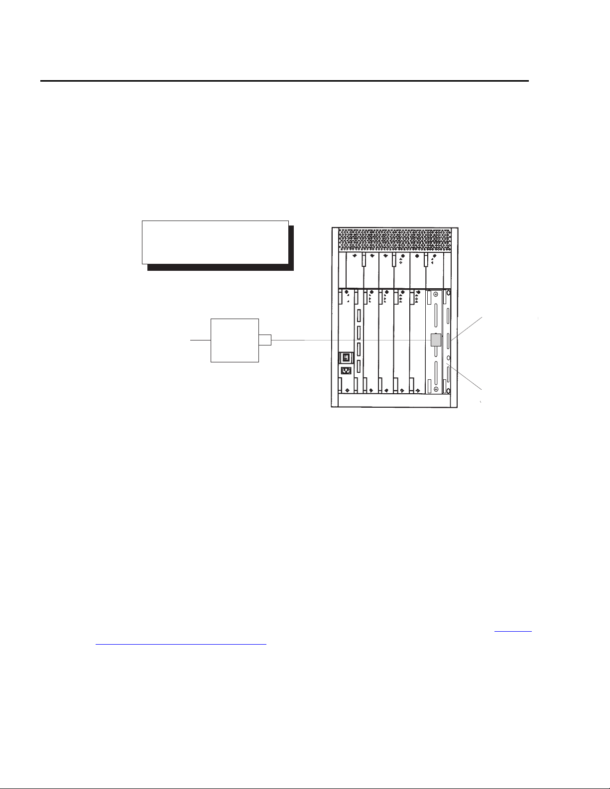
This section describes how to connect the remote console modem to the computer. This
modem allows personnel at a remote support center to dial in and perform maintenance on
the computer. The modem is a U.S. Robotics Sportster 33.6 Faxmodem, a Paradyne
Comsphere 3910 modem, or a modem provided locally.
The following figure shows remote console modem connectivity.
.
Key:
R = DB25-RJ45 ACU modem adapter
S = 10-wire modular cord
T = RJ45-DB25 remote console adapter
Telephone line
to remote
maintenance center
Modem
T
S
Serial
0
A
R
1
port A
2
B
hwremote.cdr
Clock+
board
To connect the remote console modem:
1. Connect the DB25-to-RJ45 ACU modem adapter (R) to serial port A on the Clock+
board on the back of the computer.
2. Connect the 10-wire modular cord (S) to the modular end of the ACU modem
adapter (R).
3. Connect the other end of the 10-wire modular cord (S) to the modular end of the
RJ45-to-DB25 remote console adapter (T).
4. Connect the remote console adapter (T) to the RS-232C port on the modem. The
RS-232C port on the Comsphere 3910 is labeled “DTE1.”
5. Connect the telephone line to the jack labeled “LINE” on the Sportster modem, or
labeled “DIAL” on the Comsphere 3910 modem.
6. Connect the power cable to the modem and plug it into a socket.
Do not turn on the power yet. Instructions for powering on the modem are given in Setting
the remote console modem options on page 51.
44 Avaya CMS Sun Enterprise 3500 Computer Hardware Installation, Maintenance, and Troubleshooting
Page 45

Connecting the switch link
There are two ways to connect the CMS computer to a switch:
● using TCP/IP over a local area network (LAN), or
● using X.25 protocol over a hard-wired or switched link
One CMS computer can collect data from up to eight different switches. To the CMS
computer, each switch represents one ACD. Depending on the release of the switch and
the release of the CMS software, you can have all switches connected using TCP/IP, all
switches connected using X.25 protocol, or some combination of the two protocols.
For detailed information about how to connect and administer the switch link, see Avaya
CMS Switch Connections, Administration, and Troubleshooting, 585-215-876.
Connecting the switch link
Issue 6.0 May 2005 45
Page 46
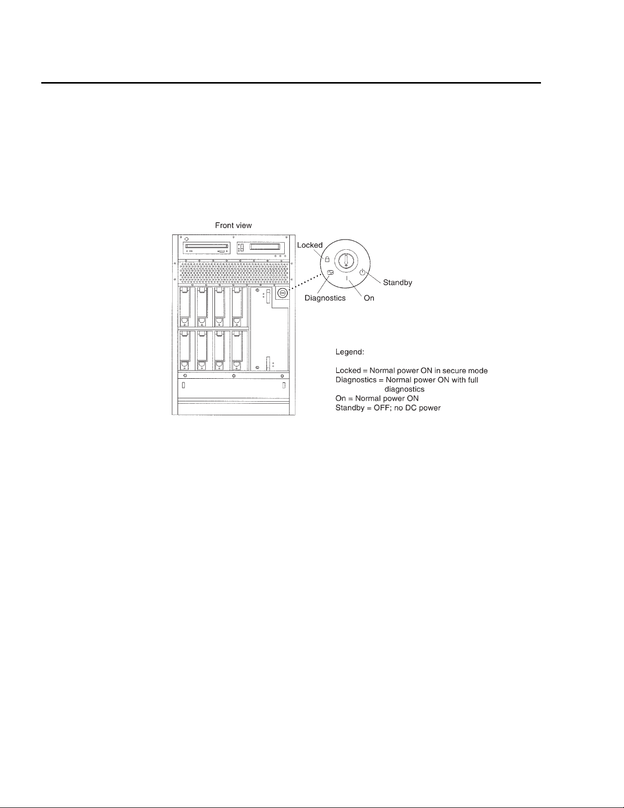
Installation
Powering up the system and verifying POST
Once you assemble the system, including the external devices that are shipped with the
system, power up the system and verify the results of the Power-On Self Test (POST).
To power up the system and verify POST:
1. Verify that the key switch is in the standby position.
key_switch.cdr
2. Plug the power cord of the UPS into an AC outlet.
3. Turn on the power to the UPS.
4. Turn on the system monitor.
5. Turn on the AC power switch at the back of the cabinet.
6. Turn the key switch to the On position.
Note:
Note: The POST diagnostics occurs each time that you turn on the system. The
POST tests the basic system components. This may take several minutes.
7. While the system is booting up, press Stop plus A simultaneously to put the system in
the monitor mode.
The ok prompt is displayed.
46 Avaya CMS Sun Enterprise 3500 Computer Hardware Installation, Maintenance, and Troubleshooting
Page 47

Powering up the system and verifying POST
8. Enter the following commands:
setenv auto-boot? false
reset-all
The system resets to the ok prompt.
9. Enter:
probe-fcal-all
This verifies that the system sees all of the fiber channel disk drives. A message that is
similar to the following is displayed:
/sbus@2,0/SUNW,socal@d,10000/sf@0,0
WWN 20050800209a80fe Loopid 1
WWN 21000020370e7255 Loopid ef
Disk SEAGATE ST19171FCSUN9.06117E9822U939
10. Verify that all of the fiber channel disk drives are recognized. If the disk drives are still
not recognized, see Troubleshooting
on page 127 for more information.
11. Enter:
reset-all
The system resets to the ok prompt.
12. Enter:
probe-scsi-all
This verifies that the system sees all SCSI devices. A message that is similar to the
following is displayed:
/sbus@3,0/SUNW,fas@3,8800000
Target 5
Unit 0 Removeable Tape EXABYTE EXB-89008E030203V37f
0060055614
Target 6
Unit 0 Removeable Read Only device TOSHIBA
XM6201TASUN32XCD110312/12/97
13. Verify that all of the SCSI devices are recognized. If the devices are still not
recognized, see Troubleshooting
on page 127 for more information.
Issue 6.0 May 2005 47
Page 48

Installation
14. When you have verified that the system recognizes all of its devices, enter the
following commands:
setenv auto-boot? true
boot -r
!
CAUTION:
CAUTION: If you fail to enter these commands, any reboots that you do in the future will
stop at the boot prompt instead of proceeding through the normal boot-up
process.
The system reboots.
48 Avaya CMS Sun Enterprise 3500 Computer Hardware Installation, Maintenance, and Troubleshooting
Page 49

Identifying installed I/O cards
Identifying installed I/O cards
The hardware inventory form that you received with the system contains a list of the I/O
cards that are installed in the system. Use this form to determine where the I/O cards are
installed. If you do not have the hardware inventory form, use the procedures below to
determine what I/O cards are installed in your system.
At the command prompt, enter:
/usr/platform/‘uname -m‘/sbin/prtdiag -v | pg
In the section called IO Cards, there is a listing of the cards. The following are examples
of some of the entries you may see. The display you see depends on your specific
configuration.
.
.
========================= IO Cards =========================
Bus Freq
Brd Type MHz Slot Name Model
--- ---- ---- ---- -------------------------------- ----------------------
1 SBus 25 0 cgsix SUNW,501-2325
1 SBus 25 1 dma/esp (scsi) SUNW,500-2015
1 SBus 25 1 lebuffer/le (network) SUNW,500-2015
1 SBus 25 2 HSI SUNW,501-1725-01
1 SBus 25 3 SUNW,hme
1 SBus 25 3 SUNW,fas/sd (block)
1 SBus 25 13 SUNW,socal/sf (scsi-3) 501-3060
.
.
In this example:
● cgsix shows the Turbo GX video card.
● dma/esp (scsi) and lebuffer/le (network) show an FSBE card, which has a
SCSI port and an ethernet port.
● HSI shows an HSI card.
● SUNW,hme shows the built-in ethernet port.
Issue 6.0 May 2005 49
Page 50
Installation
The system provides a specific name for each I/O card used in the Enterprise 3500
computer. The names for each of the cards are as follows:
I/O card name Description
ffb Creator video card (used only with
Graphics+ I/O boards)
cgsix Turbo GX video card (used only with SBus+
I/O boards)
HSI HSI/S card
lebuffer, le, ledma, esp Fast SCSI-Bus Ethernet (FSBE) card or
SunFastEthernet card
tr Token Ring interface card
The display you see depends on the equipment and configuration of your system. Use this
information to help you connect external equipment to the computer.
50 Avaya CMS Sun Enterprise 3500 Computer Hardware Installation, Maintenance, and Troubleshooting
Page 51

Setting the remote console modem options
Setting the remote console modem options
The computer uses the U.S. Robotics Sportster 33.6 Faxmodem and the Paradyne
Comsphere 3910 modem for remote console access. The options for any other modems
must be set based on local instructions.
For instructions for connecting the modem, see Connecting the remote console modem
page 44.
This section includes the following topics:
● Sportster 33.6 faxmodem on page 51
● Paradyne Comsphere 3910 modem on page 52
Sportster 33.6 faxmodem
To set the options on the Sportster 33.6 faxmodem:
1. Set DIP switches 1, 3, 7, and 8 on the back panel of the Sportster modem to the down
(ON) position, and switches 2, 4, 5, and 6 to the up (OFF) position.
2. Turn on the remote console modem.
3. At the system console, log in as root.
4. Enter:
cu -s 9600 -b 8 -l cua/a
The following message is displayed:
on
Connected
5. Enter the following commands:
at&f1 (loads the factory default configuration into active memory)
at&w0 (writes the current configuration to NVRAM template Y0)
Note:
Note: Use numerical ones and zeros when entering the options.
6. After you enter the options, disconnect from the modem by entering a tilde and a
period (~.).
7. Set DIP switches 4 and 8 on the back panel of the Sportster modem to the down (ON)
position. Set all other DIP switches to the up (OFF) position.
8. Reset the modem by turning the power off and back on.
Issue 6.0 May 2005 51
Page 52

Installation
9. If the TR LED is not lit, enter:
ps -ef | grep sac
A message similar to the following should be displayed:
root 377 1 0 14:39:30 ? 0:00 /usr/lib/saf/sac -t 300
root 9723 9666 0 09:16:26 pts/9 0:00 grep sac
Additional references - For additional information, see the U.S. Robotics Sportster
Modems Users Guide.
Paradyne Comsphere 3910 modem
The Paradyne Comsphere 3910 modem is used for many locations outside of the United
States. These modems are not optioned at the factory.
Recommended options
The recommended options for the Comsphere 3910 modem include selecting the
factory-preset defaults for “UNIX_Dial” with the following two changes:
● Asynchronous DTE Rate is changed to 9600
● Dial Line Rate is changed to 9600 (V32b)
Option buttons
The seven buttons that are used to set the modem options include:
● Single up arrow – Move up one level in the menu tree.
● Double up arrow – Move to the top-level menu.
● Left arrow – Move to the previous choice for the current level in the menu tree.
● Right arrow – Move to subsequent choice for the current level in the menu tree.
● Function 1 (F1) – Select the choice, if any, that is currently displayed above F1.
● Function 2 (F2) – Select the choice, if any, that is currently displayed above F2.
52 Avaya CMS Sun Enterprise 3500 Computer Hardware Installation, Maintenance, and Troubleshooting
Page 53
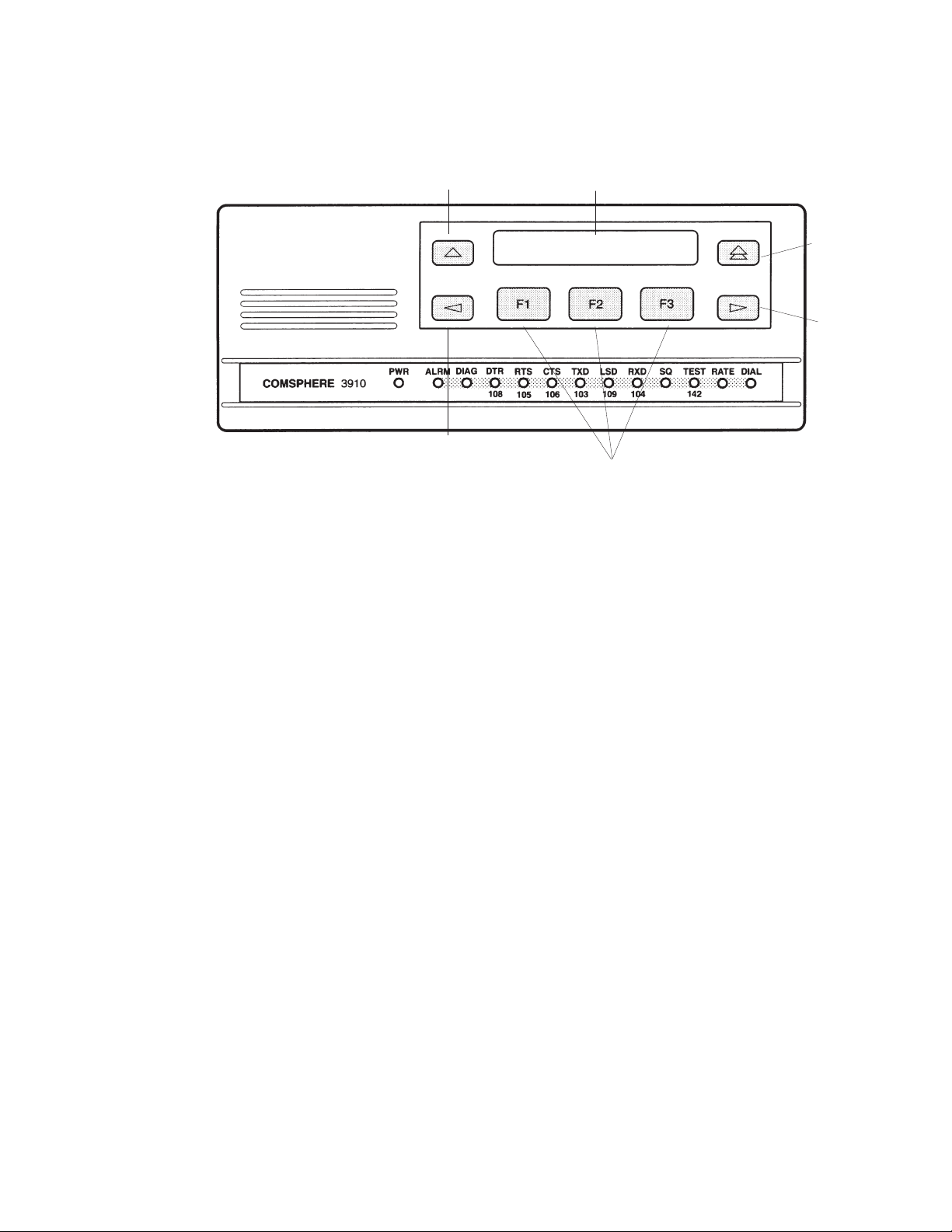
● Function 3 (F3) – Select the choice, if any, that is currently displayed above F3.
p
Setting the options
Single up
arrow
Left
arrow
Setting the remote console modem options
Display
Double u
arrow
Right
arrow
Function keys
3910.cdr
To set the options on the Comsphere 3910, use the following procedures:
Configuring Factory/Async_Dial
1. Press F2 to select “Configure.”
“Ld EditArea frm” is displayed.
2. Press the Right Arrow four times.
“Factory” is displayed.
3. Press F1 to select “Factory.”
“Ld Fact Preset:” is displayed.
4. Press Right Arrow four times.
5. Press F1 to select “UNIX_Dial.”
6. Press F3 to select “Save.”
“Sav EditArea to” is displayed.
7. Press F1 to save to “Active(Saved).”
Since you are changing the active area to a new set of options (that is, “Factory/
Async_Dial”), the modem automatically performs another Power-On-Self-Test (POST).
Since the new options match the way the modem is connected, the ALRM LED does
not turn red. “Idle: 19.2” and “Status Configure” are displayed. To return to the top-level
menu, press the Double Up Arrow.
Issue 6.0 May 2005 53
Page 54

Installation
Setting the data rate
1. Press F2 to select “Configure.”
“Ld EditArea frm” is displayed.
2. Press the Right Arrow once.
“Active(Saved)” is displayed.
3. Press F1.
“Choose Function” is displayed.
4. Press F1 to select “Edit.”
“Edit StrapGroup” is displayed.
5. Press F1 to select “DTE_Interface.”
“Async/Sync Mode” is displayed.
6. Press F1 to select “Nxt.”
“Async DTE Rate” is displayed.
7. Press the Right Arrow five times to display “9600.”
8. Press F2 to select “9600.”
Setting the handshake options
1. Press F1 for “Nxt.”
“Asyn #Data Bits (8)” is displayed.
2. Press F1 for “Nxt.”
“Asyn Parity Bit (None)” is displayed.
3. Press F1 for “Nxt.”
“Asyn #Stop Bits (1)” is displayed.
4. Press F1 for “Nxt.”
“DTR Action (Ignore)” is displayed.
5. Press F1 for “Nxt.”
“DSR Control (Forced_On)” is displayed.
6. Press F1 for “Nxt.”
“RTS Action (Ignore)” is displayed.
7. Press F1 for “Nxt.”
“CTS Control (WinkWhenDisc)” is displayed.
8. Press F1 for “Nxt.”
“RTS/CTS Delay (0 msec)” is displayed.
54 Avaya CMS Sun Enterprise 3500 Computer Hardware Installation, Maintenance, and Troubleshooting
Page 55

Setting the remote console modem options
9. Press F1 for “Nxt.”
“LSD Control (WinkWhenDisc)” is displayed.
10. Press F1 for “Nxt.”
“CT111_Rate Cntl (Disable)” is displayed.
11. Press F1 for “Nxt.”
“DTE_Rate=VF (Disable)” is displayed.
12. Press F1 for “Nxt.”
“Extend Main Ch. (Disable)” is displayed.
13. Press F1 for “End.”
“Edit StrapGroup” is displayed.
Setting the Dial_Line strap group
1. Press the Right Arrow three times to get to the “Dial_Line” strap group. Nothing needs
to be changed for CMS in the “DTE_Dialer” or “Line_Dialer” strap groups, so you can
skip them.
2. Press F1 to edit the “Dial_Line” strap group.
“Dial Line Rate” is displayed.
3. Press the Right Arrow four times for “9600(V32b).”
4. Press F2 to select “9600(V32b).”
5. Press F1 for “Nxt.”
“V32bis Automode (Enable)” is displayed.
6. Press F1 for “Nxt.”
“V32bis Autorate (Enable)” is displayed.
7. Press F1 for “Nxt.”
“Dial Tx Level (Permissv (-9))” is displayed.
8. Press F1 for “Nxt.”
“V22b Guard Tone (Disable)” is displayed.
9. Press F1 for “Nxt.”
“V32bis Train (Long)” is displayed.
10. Press F1 for “End.”
“Edit StrapGroup” is displayed. The other strap groups (“V42/MNP/Buffer,” “Test,”
“Misc,” and “Security”) are not changed for CMS.
Issue 6.0 May 2005 55
Page 56

Installation
Saving your settings
1. Press the Single Up Arrow to display “Choose Function” and “Edit Save.”
2. Press F3 to select “Save.”
“Save EditArea to” is displayed.
3. Press F1 to select “Active(Saved).”
“Command Complete” is displayed.
4. Press the Single Up Arrow again to display “Save EditArea to.”
5. Press the Right Arrow once to select “Customer 1.”
6. Press F1 to save to “Customer 1.”
“Command Complete” is displayed.
7. Press the Double Up Arrow.
“Idle: 9600” and “Status Configure” are displayed. If the modem is powered off, it
should return to this state when it is powered on.
8. To check the status of the Comsphere 3910 modem, use the “Status” choice in the
top-level menu, or use the Right and Left Arrow buttons to view other top-level menu
choices.
56 Avaya CMS Sun Enterprise 3500 Computer Hardware Installation, Maintenance, and Troubleshooting
Page 57

Turning the system over for provisioning
Turning the system over for provisioning
After completing the physical installation of the system, the installation continues with
software provisioning. This is often done with the support of the Avaya CMS Provisioning
group. Provisioning the system consists of the following:
● Setting up CMS
● Authorizing features
● Adding logins and passwords
● Testing the software
To continue with provisioning, see the chapter "Turning the system over to the customer" in
the CMS software installation, maintenance, and troubleshooting document for your CMS
release.
Issue 6.0 May 2005 57
Page 58

Installation
58 Avaya CMS Sun Enterprise 3500 Computer Hardware Installation, Maintenance, and Troubleshooting
Page 59

Maintenance
This section describes the following maintenance procedures:
● ESD precautions on page 59
● Computer layout on page 60
● Maintaining boards on page 61
● Maintaining I/O cards on page 69
● Maintaining disk drives on page 78
● Maintaining tape drives on page 109
● Adding memory and installing CPUs on page 118
● Adding or replacing a power/cooling module on page 125
ESD precautions
Before you work on components inside the Enterprise 3500 computer:
1. Make sure that the computer is plugged in to AC power.
2. Make sure that the power is off.
3. Attach the ESD wrist strap to the chassis frame and to your wrist.
Issue 6.0 May 2005 59
Page 60
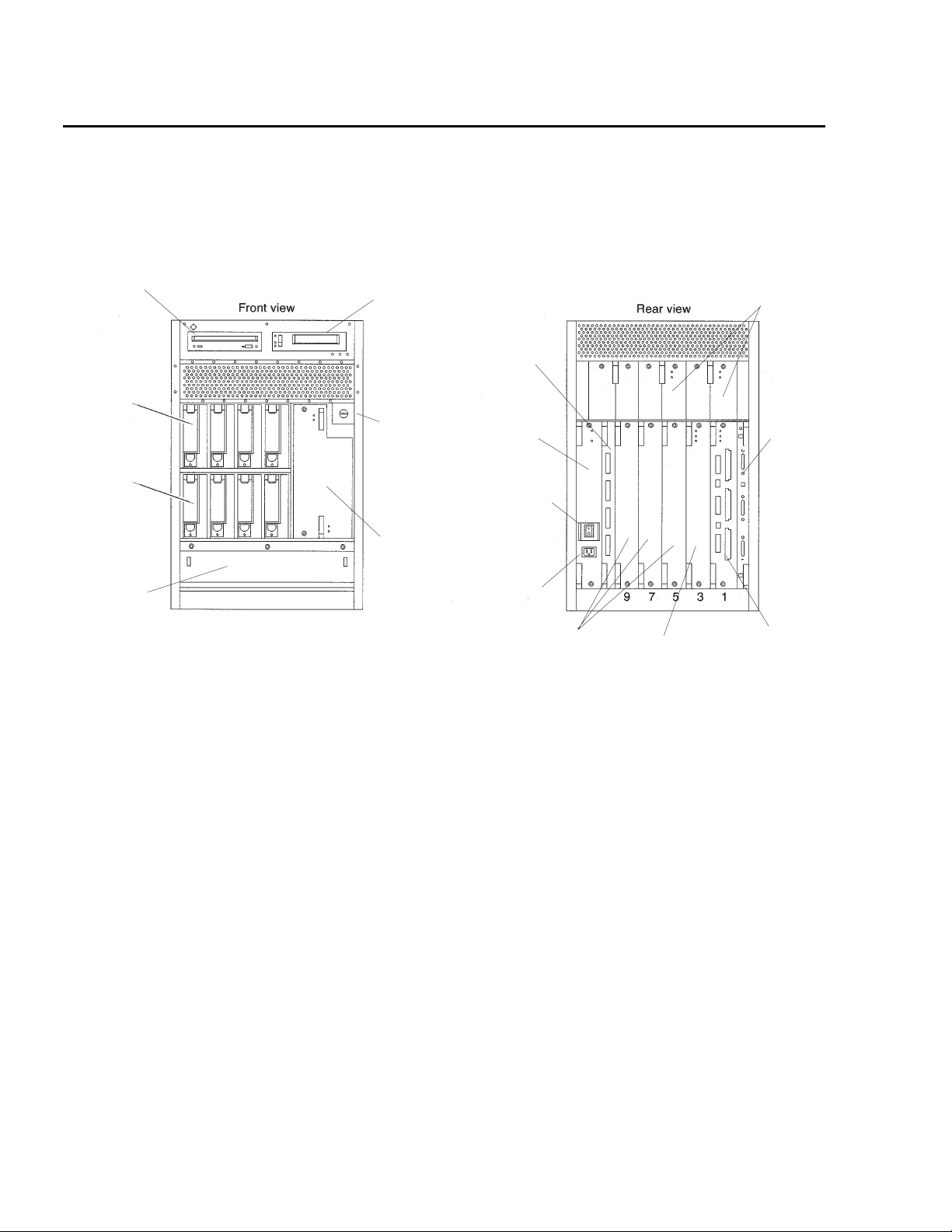
Maintenance
Computer layout
The following figure identifies the basic hardware components of the Enterprise 3500
system.
CD-ROM or
DVD-ROM
Disk
drives
(mirrored)
Disk
drives
(mirrored and
nonmirrored)
Fan tray
3500_cab.cdr
7654
0123
Tape
drive
Key
switch
Auxiliary peripheral
power supply
or
thermal protection
module
FC-AL interface
board
Peripheral
power supply
(PPS)
AC power
switch
AC
connector
Filler
panels
CPU/Memory+
board
Power cooling
modules (PCM)
Clock+
board
I/O board
(Graphics+
or SBus+)
60 Avaya CMS Sun Enterprise 3500 Computer Hardware Installation, Maintenance, and Troubleshooting
Page 61
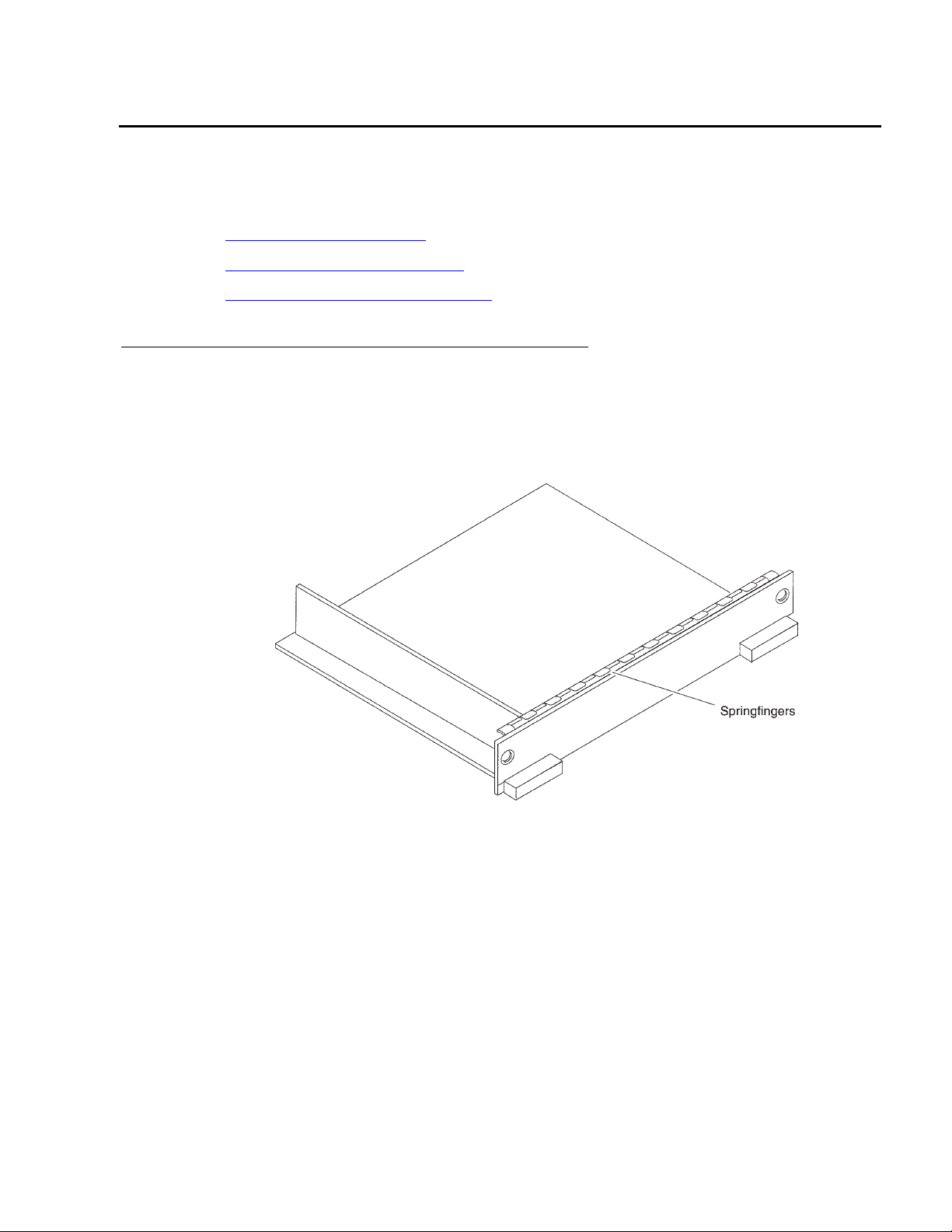
Maintaining boards
Procedures in this section include the following:
● Identifying free board slots on page 61
● Removing and installing boards on page 62
● Maintaining the system clock board on page 66
Identifying free board slots
Free board slots are covered by filler panels, which have rectangular plastic knobs instead
of extraction levers. The following figure shows a filler panel.
Maintaining boards
(Top)
filler.cdr
Issue 6.0 May 2005 61
Page 62
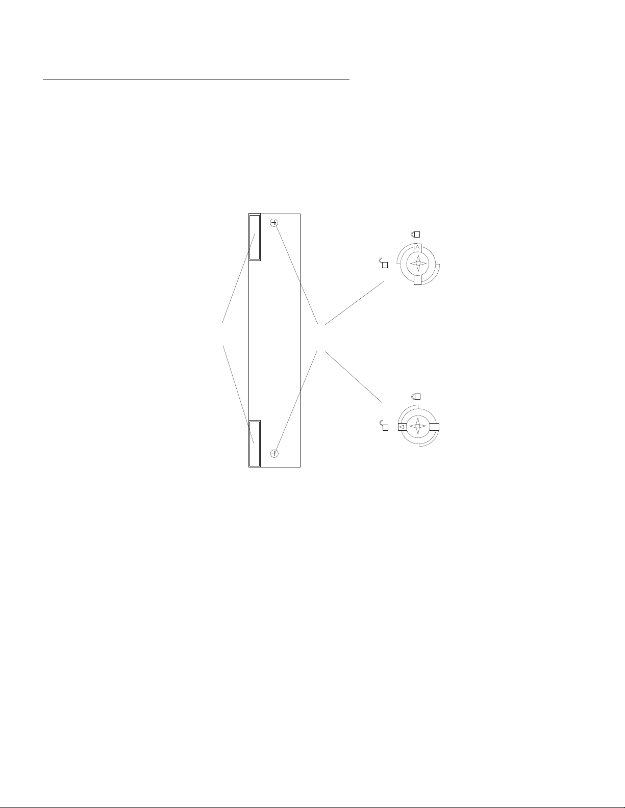
Maintenance
Removing and installing boards
This section describes general procedures for removing and installing boards. Boards are
accessed from the rear of the system. Each board is locked into place by a combination of
extraction levers and board locks that help to seat the board in the centerplane
receptacles. These centerplane receptacles and board locks align and attach the board to
the system. The following figure shows the board-locking mechanisms.
Locked Position
locked
Extraction
Levers
Board
Locks
Unlocked Position
unlocked
access.cdr
62 Avaya CMS Sun Enterprise 3500 Computer Hardware Installation, Maintenance, and Troubleshooting
Page 63

Precautions for handling boards
To minimize the amount of board flexing, observe the following precautions:
!
WARNING:
WARNING: You must wear an ESD wrist strap when installing or removing hardware
components to prevent electrical discharge that can damage the system.
!
WARNING:
WARNING: The CPU/Memory+ and I/O boards, and their modules and cards, have
surface-mounted components that can break if you flex the boards.
● Hold the board only by the edges near the middle of the board, where the board stiffener
is located. Do not hold the board only at the ends.
● When you remove the board from an antistatic bag, keep the board vertical until you lay
it on an ESD mat.
● Do not place the board on a hard surface. Use a cushioned antistatic mat. The board
connectors and components have very thin pins that bend easily.
● Transport the board in an antistatic bag.
Maintaining boards
● Be careful of the small parts that are located on the component side of the board.
Removing a board
To remove a board:
!
CAUTION: A board should be removed from a powered-on system only after the
1. Check to see that the board is in a “low-power mode.” A board is in low-power mode
when:
● All three LEDs on the board rear panel are unlit (power is turned off), or
● The two outer green LEDs are unlit and the yellow LED in the middle is lit.
2. If the board is not in a low-power mode, stop the system and turn off the power.
3. Using a Phillips screwdriver, turn the two board locks to the unlocked position.
4. Pull outward on the ends of both extraction levers simultaneously.
5. Slide the board out of the computer.
CAUTION:
Automatic System Reconfiguration (ASR) software has disabled that board.
Otherwise, the operating system must be stopped and the system powered
off prior to board removal.
6. Place the board on a padded ESD mat or store the board in an antistatic bag.
Issue 6.0 May 2005 63
Page 64

Maintenance
Installing a board
To install a board:
1. Open the extraction levers by pulling outward on the ends of both levers.
2. Insert the board part of the way into the slot, with the component side of the board on
your right.
3. Slide the board into the computer, and push in on the extraction levers until they lock.
!
WARNING: Do not push on the panel. if you do, you will damage the connector pins.
4. Using a Phillips screwdriver, rotate the board locks into the locked position.
5. Turn on power to the system, or reboot.
Note:
Note: Adding a board may require that you also add a PCM. There must be one
WARNING:
PCM for every two boards that are installed in the system. The PCMs must
be installed adjacent to populated board slots to ensure that the fan in the
PCM can cool the associated boards.
Resetting the EEPROM settings
If you replace a system board, you must check and reset the EEPROM settings. For a
listing of the correct settings, see “Displaying and setting the EEPROM parameters” in the
CMS software installation, maintenance, and troubleshooting document for your CMS
version.
64 Avaya CMS Sun Enterprise 3500 Computer Hardware Installation, Maintenance, and Troubleshooting
Page 65

Synchronizing the clocks
Each I/O board has its own clock that must be synchronized with the system clock board
for proper system operation. After adding, removing, or replacing an I/O board or the
system clock board, the clock on the I/O board might become unsynchronized with the
clock on the system clock board.
If the clocks need resynchronizing, the following message is displayed when you reboot:
Clock board TOD does not match TOD on any IO board
To synchronize the clocks:
1. If CMS is running, turn it off.
2. Enter:
/usr/sbin/shutdown -y -g0 -i0
The system shuts down and displays the ok prompt.
3. Enter:
copy-clock-tod-to-io-boards
Maintaining boards
This synchronizes the clocks.
4. Enter:
boot -r
This reboots the system and resynchronizes the clocks.
5. Turn CMS on.
Issue 6.0 May 2005 65
Page 66

Maintenance
Maintaining the system clock board
These procedures should be performed by or with the assistance of a Sun Microsystems
Inc. technician.
Replacing the system clock board
To replace the system clock board:
1. Shut down the system
2. Remove the faulty clock board.
3. Remove the nonvolatile random access memory (NVRAM) chip from the old clock
board and insert it into the new clock board.
4. Install the new clock board in the system.
5. Power up the system.
If this does not solve the problem, you must replace the NVRAM chip. When the NVRAM
chip is replaced, all EEPROM settings are reset to the Sun factory default values. Some of
the settings must be changed to the EEPROM parameter values required by CMS. For a
listing of the correct CMS settings, see “Displaying and setting the EEPROM parameters”
in the CMS software installation, maintenance, and troubleshooting document for your
CMS version.
If you replace the NVRAM chip on an older system that is using X.25 software, you will
need to call Sun Microsystems Inc. to obtain a new license key. On newer systems, you
may not have to reinstall the license.
66 Avaya CMS Sun Enterprise 3500 Computer Hardware Installation, Maintenance, and Troubleshooting
Page 67

Setting the boot device on a new NVRAM chip
If the NVRAM chip has been replaced, use the following procedure to insure that the boot
device is set correctly.
To display and set the boot device:
1. At the UNIX prompt, enter:
eeprom | grep boot-device
On a non-mirrored system, the system should display a message similar to the
following:
boot-device=disk
#
On a mirrored system, the system should display a message similar to the following:
boot-device=disk bootdevice2
#
2. If the first device displayed on a nonmirrored system is not disk, enter:
Maintaining boards
eeprom boot-device=disk
If the first and second devices displayed on a mirrored system are not disk and
bootdevice2, enter:
eeprom boot-device=disk bootdevice2
3. Enter:
/usr/sbin/shutdown -y -g0 -i6
This reboots the system so that is recognizes the new configuration.
If the system still does not boot, but reports that it is trying to boot up from the network:
1. Enter:
printenv boot-device
2. Check the first parameter. If it is not disk, enter:
setenv boot-device disk
If you have a mirrored system, enter:
setenv boot-device disk bootdevice2
3. Enter:
/usr/sbin/shutdown -y -g0 -i6
This reboots the system so that is recognizes the new configuration.
Issue 6.0 May 2005 67
Page 68

Maintenance
If the system still does not boot, see the procedures given in Resetting a device alias on
page 167.
Synchronizing the clocks
Each I/O board has its own clock that must be synchronized with the system clock board
for proper system operation. After adding, removing, or replacing an I/O board or the
system clock board, the clock on the I/O board might become unsynchronized with the
clock on the system clock board.
If the clocks need resynchronizing, the following message is displayed when you reboot:
Clock board TOD does not match TOD on any IO board
To synchronize the clocks:
1. If CMS is running, turn it off.
2. Enter:
/usr/sbin/shutdown -y -g0 -i0
The system shuts down and displays the ok prompt.
3. Enter:
copy-clock-tod-to-io-boards
This synchronizes the clocks.
4. Enter:
boot -r
This reboots the system and resynchronizes the clocks.
5. Turn CMS on.
68 Avaya CMS Sun Enterprise 3500 Computer Hardware Installation, Maintenance, and Troubleshooting
Page 69

Maintaining I/O cards
This section includes the following topics:
● Required references on page 69
● I/O card compatibility with CMS loads on page 70
● Installing or removing I/O cards on page 70
● Installing HSI/S cards on page 73
Required references
You need access to the following documents to do the procedures in this section:
● Sun Enterprise 3500 System Reference Manual
● CMS R12 Software Installation, Maintenance, and Troubleshooting, 585-215-117
Maintaining I/O cards
● CMS R3V11 Software Installation, Maintenance, and Troubleshooting, 585-215-115
● CMS R3V9 Software Installation, Maintenance, and Troubleshooting, 585-215-956
● CMS R3V8 Software Installation, Maintenance, and Troubleshooting, 585-210-941
● CMS Software Installation and Setup (R3V5 and R3V6), 585-215-866
● CMS Switch Connections, Administration, and Troubleshooting, 585-215-876
Issue 6.0 May 2005 69
Page 70

Maintenance
I/O card compatibility with CMS loads
New I/O cards are not compatible with all releases of CMS. This section describes the
compatibility of newer I/O cards.
SunFastEthernet I/O card
The SunFastEthernet card is compatible with the following releases of CMS:
● r3v6au.k and later (or any CMS R3V6 load with Solaris patch 104212-15)
● r3v8al.k with Solaris patch 108263-06, or r3v8am.X and later
● all R3V9 loads
Solaris patches can be downloaded from:
http://drdtl.dr.avaya.com/docs/patches/
Installing or removing I/O cards
The I/O cards you may have to install or remove include the following:
● Creator video card (installed in card slot 1 of the Graphics+ I/O board in board slot 1)
● TurboGX+ video card (installed in card slot 0 of the SBus+ I/O board in board slot 1)
● SunFastEthernet card (optional) – This card has an ethernet port and a Media
Independent Interface (MII) port. CMS uses only the ethernet port.
● FSBE card (optional) – This card has a SCSI port and an ethernet port.
● SunSwift card (optional) – This card has an ethernet port.
● HSI card (optional)
● Token Ring card (optional, installed by the factory and provisioned by Professional
Services)
As noted above, the video cards are installed in specific card slot locations depending on
the board type. Only one video card is installed per system. The other I/O cards can be
installed in any other available SBus card slots.
Use the following general instructions when installing, moving, and removing I/O cards.
Other sections in this section describe specific I/O card maintenance instructions. Use
those instructions as appropriate.
To install or remove an I/O card:
1. For a system that is currently in operation, verify that you have a recent CMSADM file
system backup before you change I/O card configurations.
70 Avaya CMS Sun Enterprise 3500 Computer Hardware Installation, Maintenance, and Troubleshooting
Page 71
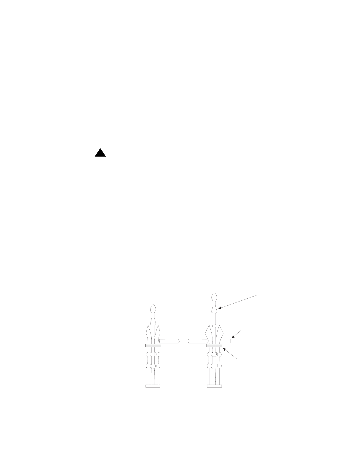
Maintaining I/O cards
2. Enter:
/cms/toolsbin/rmSBusdev
The system queries whether you want to continue with the shutdown.
3. Enter: y
This command removes the current I/O card configuration, and shuts down the
system. When finished, the ok prompt displays.
4. Turn off the system.
5. Turn off the system monitor.
6. Turn off all external SCSI devices starting with the device that is closest to the system
and working toward the farthest device.
!
WARNING:
WARNING: You must wear an ESD wrist strap when installing or removing hardware
components to prevent electrical discharge that can damage the system.
7. Remove the I/O board from the computer.
8. Remove the filler panel from the slot where you are installing the new card.
9. Unpack the I/O card and prepare it for installation.
Note:
Note: Depending on the card and packaging, some card preparation may be
required. See the Sun Enterprise 3500 System Reference Manual for more
information.
10. If the plastic standoffs for the I/O card slot are locked (that is, if they are in the down
position), gently but firmly lift up on the tip inserts until they move to the unlocked
position.
UnlockedLocked
Tip insert
Card
Flange
stndoffs.cdr
Issue 6.0 May 2005 71
Page 72
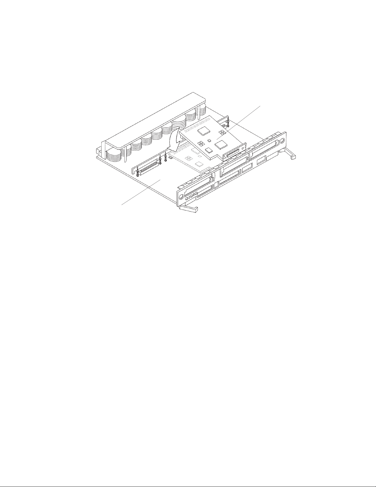
Maintenance
11. Holding the I/O card by the edges, place the I/O card faceplate under the spring finger
and against the rear face of the I/O board front panel.
The I/O connectors of the I/O card should be visible through the slot opening in the I/O
board front panel.
I/O card
(Top)
I/O board
install_card.cdr
12. Align the mounting holes in the rear of the I/O card with the unlocked plastic standoffs.
13. Gently but firmly press down on the rear corners of the I/O card until the connector is
fully seated.
14. Gently but firmly press down on the tip insert of each plastic standoff until it seats into
the locked position.
15. Replace the face plate screws through the front of the I/O board to secure the I/O card
to the I/O board front panel.
16. Replace the I/O board in the slot from which you removed it in Step 1.
17. Remove the ESD wrist strap.
18. Turn on all external SCSI devices starting with the device that is farthest from the
system and working toward the system.
19. Turn on the system monitor.
20. Turn on the system.
21. Press Stop plus A simultaneously after the console banner is displayed, but before the
system starts booting.
22. Enter:
boot -r
This reboots the system so that it recognizes the new configuration.
72 Avaya CMS Sun Enterprise 3500 Computer Hardware Installation, Maintenance, and Troubleshooting
Page 73

23. Perform a CMSADM file system backup to back up the updated system configuration.
See your CMS software installation, maintenance, and troubleshooting document for
details.
Installing HSI/S cards
An HSI/S card supports X.25 switch links. For eight ACDs, two HSI/S cards are needed. If
the system uses TCP/IP signaling for all ACDs, HSI/S cards are not needed.
If this is the initial installation of one or two HSI/S cards, start with Installing the first HSI/S
card. If a second HSI/S card is being added to a system that already has one HSI/S card,
see Adding a second HSI/S card
Installing the first HSI/S card
To install the first HSI/S card in the system:
1. Verify that you have a recent CMSADM file system backup before you change I/O card
configurations.
Maintaining I/O cards
on page 76.
2. Log in to the system as root.
3. Enter:
cmssvc
The CMS Services menu is displayed.
4. Enter 3 to select the run_cms option.
5. Enter 2 to turn off CMS
6. Before you remove CMS, you must first save the CMS tools in a temporary save
directory. Enter the following two commands:
if [ ! -d /save ]; then mkdir /save; fi
cp -p /cms/toolsbin/rmSBusdev /cms/toolsbin/lnSBusdev /save
7. Enter:
pkgrm cms
This removes the CMS software.
The system runs the pkgrm command and displays the following message:
Do you want to preserve CMS data? [y,n,?]
!
!
Important:
Important:
Important: Enter: y
Issue 6.0 May 2005 73
Page 74

Maintenance
8. After you remove CMS, you must copy the CMS tools back in to their working directory.
Enter the following two commands:
if [ ! -d /cms/toolsbin ]; then mkdir /cms/toolsbin; fi
cp -p /save/rmSBusdev /save/lnSBusdev /cms/toolsbin/
9. Enter:
/cms/toolsbin/rmSBusdev
The system queries whether you want to continue with the shutdown.
10. Enter: y
This removes the current I/O card configuration, and shuts down the system. When
finished, the ok prompt is displayed.
11. Turn off the system.
12. Turn off the system monitor.
13. Turn off all external SCSI devices starting with the device that is closest to the system
and working toward the farthest device.
14. Install the HSI/S card in an available port on the first-available I/O board. See Installing
or removing I/O cards on page 70 for more information.
15. Attach the HSI/S patch panel, and connect the switch links to the patch panel by
following the instructions described in Avaya CMS Switch Connections, Administration,
and Troubleshooting, 585-215-876.
16. Turn on all external SCSI devices starting with the device that is farthest from the
system and working toward the system.
17. Turn on the system monitor.
18. Turn on the system.
19. Press Stop plus A simultaneously after the console banner is displayed, but before the
system starts booting.
20. Enter:
boot -r
This reboots the system so that it recognizes the new HSI/S card.
Note:
Note: Sometimes the system fails to recognize a newly installed HSI card. If this
happens, the command show-devs does not show the HSI card and /
var/adm/messages fails to recognize the card upon bootup. See the
troubleshooting chapter of Avaya CMS Switch Connections, Administration,
and Troubleshooting, 585-215-876, for information about troubleshooting
HSI/S cards.
21. When the system comes back up, log in as root.
74 Avaya CMS Sun Enterprise 3500 Computer Hardware Installation, Maintenance, and Troubleshooting
Page 75

Installing HSI/S software and patches
Using the procedures in the CMS software installation, maintenance, and troubleshooting
document:
● Install the HSI/S software
● Install the X.25 drivers and license
● Reinstall the Solaris patches
● Reinstall the CMS software
Setting up the switch link for each ACD
To change the switch link administration for each ACD:
1. Enter:
cmssvc
The CMS Services menu is displayed.
2. Select the swsetup option.
Maintaining I/O cards
3. Select the ACD that you want to set up.
4. Accept the existing defaults for the following:
● Switch name
● Switch model (release)
● Vectoring
● Expert agent
● Central office disconnect supervision
● Local port
● Remote port
5. Select “X.25” and a specific link number when prompted for the link information.
6. Repeat Step 2 through Step 5 for each ACD that will use the HSI card.
7. Perform a CMSADM file system backup to back up the updated system configuration.
See your CMS software installation, maintenance, and troubleshooting document for
details.
8. Turn on CMS using the run_cms option of the cmssvc command.
Issue 6.0 May 2005 75
Page 76

Maintenance
Adding a second HSI/S card
Use the following procedures if you are adding a second HSI/S card to a system that is
currently in operation. Before you do this procedure, verify that CMS is installed.
To add a second HSI/S card:
1. Verify that you have a recent CMSADM file system backup before you change I/O card
configurations.
2. Log in to the system as root.
3. Edit the /etc/path_to_inst file and search for HSI. Remove all such lines.
4. Enter the following commands:
rm /dev/hih*
rm /devices/sbus*/HSI*
5. Enter:
/usr/sbin/shutdown -y -i0 -g0
This shuts down the system.
6. Turn off the system.
7. Turn off the system monitor.
8. Turn off all external SCSI devices starting with the device that is closest to the system
and working toward the farthest device.
9. Install the second HSI/S card in an available port on the first-available I/O board. See
Installing or removing I/O cards
on page 70 for more information.
10. Attach the HSI/S patch panel, and connect the switch links to the patch panel by
following the instructions in Avaya CMS Switch Connections, Administration, and
Troubleshooting, 585-215-876.
11. Turn on all external SCSI devices starting with the device that is farthest from the
system and working toward the system.
12. Turn on the system monitor.
13. Turn on the system.
14. Press Stop plus A simultaneously after the console banner is displayed, but before the
system starts booting.
76 Avaya CMS Sun Enterprise 3500 Computer Hardware Installation, Maintenance, and Troubleshooting
Page 77

Maintaining I/O cards
15. Enter:
boot -r
This reboots the system so that it recognizes the new HSI/S card.
Note:
Note: Sometimes the system fails to recognize a newly installed HSI card. If this
happens, the command show-devs does not show the HSI card and /
var/adm/messages fails to recognize the card upon bootup. See the
troubleshooting chapter of Avaya CMS Switch Connections, Administration,
and Troubleshooting, 585-215-876, for information about troubleshooting
HSI/S cards.
16. When the system comes back up, log in as root.
17. Enter:
/cms/toolsbin/lnSBusdev
18. Administer the switch links as shown in Setting up the switch link for each ACD
page 75.
on
Issue 6.0 May 2005 77
Page 78

Maintenance
Maintaining disk drives
This section includes the following topics:
● Disk drive compatibility with CMS loads on page 78
● Prerequisites on page 78
● Required references on page 79
● Adding or replacing disk drives on page 79
● Setting up the disk drives on page 82
● Partitioning disk drives on page 84
● Administering data disk drives on page 94
● Replacing the CD-ROM or DVD-ROM drive on page 106
Disk drive compatibility with CMS loads
When a new or replacement disk drive is installed in an older system, the CMS load may
not be compatible with the disk drive if the CMS configuration files have not been updated.
These configuration files (/olds/disk.conf and /olds/olds-funcs) must be edited
or replaced with the correct information. Contact the Avaya technical support organization
for assistance.
Prerequisites
Do a CMSADM backup, if possible, before you add or replace a disk drive. See your CMS
software installation, maintenance, and troubleshooting document for this procedure.
Before you attempt to replace defective data disks, try to print the current setup for all
ACDs. This information must be readministered after you install replacement disks.
78 Avaya CMS Sun Enterprise 3500 Computer Hardware Installation, Maintenance, and Troubleshooting
Page 79

Required references
You need access to the following documents to do the procedures in this section:
● CMS R12 Software Installation, Maintenance, and Troubleshooting, 585-215-117
● CMS R3V11 Software Installation, Maintenance, and Troubleshooting, 585-215-115
● CMS R3V9 Software Installation, Maintenance, and Troubleshooting, 585-215-956
● CMS R3V8 Software Installation, Maintenance, and Troubleshooting, 585-210-941
● CMS Software Installation and Setup (R3V5 and R3V6), 585-215-866
● CMS R3V8 Disk-Mirrored Systems, 585-210-940
● CMS Disk-Mirrored Systems (for R3V6), 585-215-841
● Sun Enterprise 3500 System Reference Manual
Adding or replacing disk drives
Maintaining disk drives
To add a hard disk drive to a system that is currently in operation, or to replace a defective
disk drive, follow the procedures in this section.
Powering down the system
To power down the system
1. Enter:
/usr/sbin/shutdown -y -i0 -g0
The system shuts down and displays the ok prompt.
2. Turn off the system.
3. Turn off the system monitor.
4. If any external SCSI devices are installed, turn off the SCSI devices starting with the
device that is closest to the system and working toward the farthest device.
5. Wait 30-60 seconds after removing power to allow the disk drives to spin down.
Issue 6.0 May 2005 79
Page 80
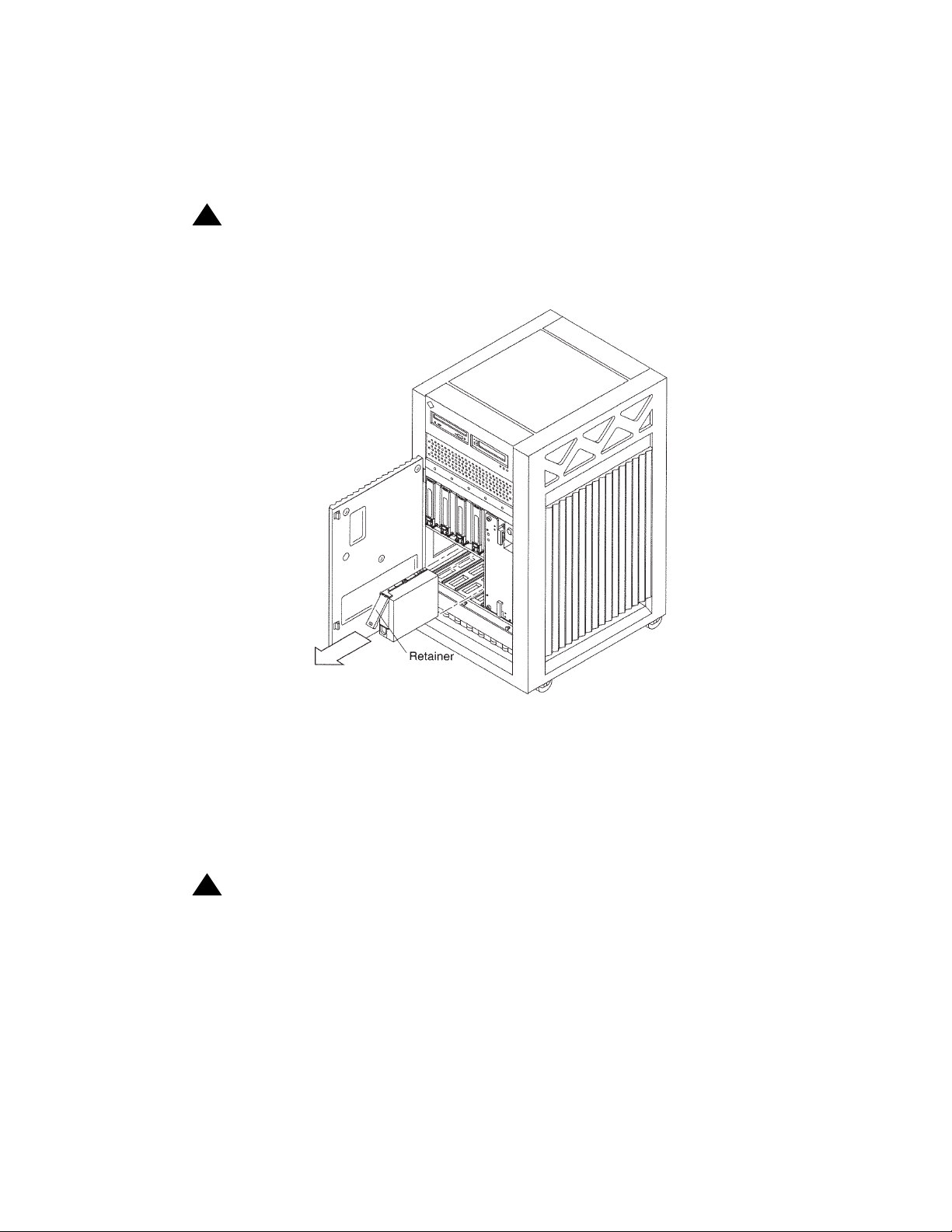
Maintenance
Installing the new drives
You install the internal hard disk drives in the front of the system. To expose the disk drive
bays, open the front access door.
!
WARNING:
WARNING: You must wear an ESD wrist strap when installing or removing disk drives to
prevent electrical discharge that can harm system components.
e3500_remove_disk.cdr
For a CMS computer, you can install as many as four disk drives in a nonmirrored system,
and eight in a mirrored system. For an Explorer II/NICE Analyzer computer, you can install
as many as eight disk drives. The drive bays are numbered 0 through 3 on the lower level
and 4 through 7 on the upper level.
In a CMS mirrored system, disk drives must be installed in pairs, and each pair must be the
same size. For example, if you have disks in positions 0 and 1, the mirrored disks must be
located in positions 4 and 5.
!
WARNING:
WARNING: Do not use excessive force to seat the connector or to close the retainer
latch. Using excessive force can damage the disk drive and computer.
Each disk drive has a retainer latch/drive handle on the front of the drive. To install a drive,
unlatch and extend the retainer and slide the drive carefully into the appropriate drive bay.
When the drive stops, gently apply pressure to the face of the drive until the connectors
engage. Lower the retainer latch and snap it in place, making certain that the drive is
secure and does not extend beyond the front of the chassis.
80 Avaya CMS Sun Enterprise 3500 Computer Hardware Installation, Maintenance, and Troubleshooting
Page 81

Powering up the system
To power up the system:
1. Turn on all external SCSI devices starting with the device that is farthest from the
system and working toward the system.
2. Turn on the system monitor.
3. Turn on the system.
4. Press Stop plus A simultaneously after the console banner is displayed, but before the
system starts booting.
The ok prompt is displayed.
5. Enter the following commands:
setenv auto-boot? false
reset-all
The system reboots to the ok prompt.
6. Enter:
Maintaining disk drives
probe-fcal-all
This verifies that the system recognizes all of the disk devices, including the newly
installed ones. A message that is similar to the following example is displayed:
WWN 20050800209a80fe Loopid 1
WWN 21000020370e7255 Loopid ef
Disk SEAGATE ST19171FCSUN9.0G117E9822U939
ok
The devices listed depends on the number of disks that are installed in the system.
Issue 6.0 May 2005 81
Page 82

Maintenance
7. Enter the following commands:
setenv auto-boot? true
boot -r
!
CAUTION:
CAUTION: If you fail to enter these commands, any reboots that you do in the future will
stop at the boot prompt instead of proceeding through the normal boot-up
process.
The system reboots.
8. Log in as root.
9. Continue with Setting up the disk drives
Setting up the disk drives
After you replace defective disk drives, do one of the following:
Drive replaced System Procedure
Boot disk Nonmirrored Continue with the CMSADM restore procedure for a
Both boot disks Mirrored Continue with the CMSADM restore procedure for a
One boot disk Mirrored Partition the new boot disk drive (see Partitioning disk
on page 82.
nonmirrored system in the Maintenance chapter of the
software installation, maintenance, and
troubleshooting document for your version of CMS.
mirrored system in the Maintenance chapter of the
software installation, maintenance, and
troubleshooting document for your version of CMS.
drives on page 84). Continue with the procedures in
“Recovering a mirrored system after disk failure” in the
Maintenance chapter of the software installation,
maintenance, and troubleshooting document for your
version of CMS.
82 Avaya CMS Sun Enterprise 3500 Computer Hardware Installation, Maintenance, and Troubleshooting
Page 83
Maintaining disk drives
Drive replaced System Procedure
Data disk Mirrored Partition and administer the drive so that it works with
the existing disk drives (see Partitioning disk drives
page 84 and Administering data disk drives on
page 94). Continue with the procedures in
“Recovering a mirrored system after disk failure” in the
Maintenance chapter of the software installation,
maintenance, and troubleshooting document for your
version of CMS.
Data disk Nonmirrored Partition and administer the drive so that it works with
the existing disk drives (see Partitioning disk drives
page 84 and Administering data disk drives
on
page 94). Continue with the procedures in
“Recovering a nonmirrored system after data disk
failure” in the Maintenance chapter of the software
installation, maintenance, and troubleshooting
document for your version of CMS.
After you add new disk drives, do the following:
on
on
Drive added System Procedure
Data disk Mirrored or
nonmirrored
Partition and administer the drive so that it works with
the existing disk drives (see Partitioning disk drives
page 84 and Administering data disk drives on
page 94).
on
Issue 6.0 May 2005 83
Page 84

Maintenance
Partitioning disk drives
Requirements for partitioning disk drives differs for the releases of CMS.
R3V11 and R12
If you are adding new disk drives to a system where CMS is operational, partitioning is
done automatically using CMS commands. Skip manual partitioning and continue with
Administering data disk drives
If you are replacing a defective data disk drive in a system and CMS is not operational, or if
you are replacing a single defective boot disk in a mirrored system, you must manually
partition the disk drive. Use the following information:
● Disk partition values, R3V11 and R12 boot disks on page 85 or R3V11 and R12 data
disks on page 87
● Partitioning and formatting a disk on page 90
R3V9
on page 94.
If you are adding new disk drives to a system where CMS is operational, partitioning is
done automatically using CMS commands. Skip manual partitioning and continue with
Administering data disk drives
If you are replacing a defective data disk drive in a system and CMS is not operational, or if
you are replacing a defective boot disk in a mirrored system, you must manually partition
the disk drive. Use the following information:
● Disk partition values, R3V9 boot disks on page 86 or R3V9 data disks on page 87
● Partitioning and formatting a disk on page 90
R3V8 and earlier
For R3V8 and earlier systems, you must partition and format the new or replacement disk
drives. Use the following information:
● Disk partition values, R3V8 and earlier data disks on page 89
● Partitioning and formatting a disk on page 90
on page 94.
84 Avaya CMS Sun Enterprise 3500 Computer Hardware Installation, Maintenance, and Troubleshooting
Page 85
Disk partition values
During the disk partitioning procedure, you must enter the size of each partition. Since disk
models change often, see the software installation, maintenance, and troubleshooting
document for your current CMS release to verify the correct disk partitioning values.
R3V11 and R12 boot disks - The following table lists the boot disk drives for R3V11 and
R12. These partition sizes are entered in Gigabytes (gb).
Maintaining disk drives
Disk Partition ID tag Permission
Starting cylinder Value
flag
36-GB
0 root wm 0 4gb
1 swap wu 2904 1gb
1
2
backup wm Use the default values for partition 2.
3 un wm 3630 3gb
4 un wm 5808 2gb
5-7 un wm Do not enter a value for partitions 5
through 7. These values are
populated automatically when the
boot disks resynchronize during the
restore procedure.
1. The value that is displayed for the backup partition shows the size of the disk drive. If the disk drive
you are partitioning does not closely match the size of the disk you are partitioning (for
example, 26-GB for a 36-GB disk), you have a nonstandard disk. Escalate the issue to Avaya
technical support.
Issue 6.0 May 2005 85
Page 86
Maintenance
R3V9 boot disks - The following table lists the boot disk drives that are currently used with
R3V9 and later. These partition sizes are entered in gigabytes (gb) and cylinders (c).
Disk Partition ID tag Permission
flag
36-GB
0 root wm 0 4gb
1 swap wu 2904 1gb
2 backup wm Use the default values for partition 2.
3 un wm 3630 3gb
4 un wm 5808 2gb
5 un wm 7260 2gb
6 un wm 8712 2gb
7 un wm 10164 14456c
18-GB
0 root wm 0 4gb
1 swap wu 1781 1gb
2 backup wm Use the default values for partition 2.
3 un wm 2227 3gb
4 un wm 3563 2gb
Starting cylinder Value
5 un wm 4454 2gb
6 un wm 5345 2gb
7 un wm 6236 1270c
86 Avaya CMS Sun Enterprise 3500 Computer Hardware Installation, Maintenance, and Troubleshooting
Page 87
Maintaining disk drives
R3V11 and R12 data disks - The following table lists the data disk drives. These partition
sizes are entered in Gigabytes (gb) and cylinders (c).
Disk Partition ID tag Permission
flag
36-GB
0un wm 02gb
Starting
cylinder
Value
1 un wm 891 2gb
1
2
backup Do not enter a value for partition 2.
3 un wm 1782 2gb
4 un wm 2673 2gb
5 un wm 3564 2gb
6 un wm 4455 2gb
7 un wm 5346 2160c
1. The value that is displayed for the backup partition shows the size of the disk drive. If the disk drive
you are partitioning does not closely match the size of the disk you are partitioning (for
example, 26-GB for a 36-GB disk), you have a nonstandard disk. Escalate the issue to Avaya
technical support.
R3V9 data disks - The following table lists the data disk drives that are currently
supported with R3V9 and later. These partition sizes are entered in gigabytes (gb) and
cylinders (c).
Disk Partition ID tag Permission
flag
36-GB
0un wm 02gb
1 un wm 1452 2gb
1
2
backup Do not enter a value for partition 2.
3 un wm 2904 2gb
4 un wm 4356 2gb
5 un wm 5808 2gb
6 un wm 7260 2gb
7 un wm 8712 15908c
Starting
Value
cylinder
Issue 6.0 May 2005 87
Page 88
Maintenance
Disk Partition ID tag Permission
flag
18-GB
0un wm 02gb
1 un wm 891 2gb
1
2
backup Do not enter a value for partition 2.
3 un wm 1782 2gb
4 un wm 2673 2gb
5 un wm 3564 2gb
6 un wm 4455 2gb
7 un wm 5346 2160c
9.1-GB
0un wm 02gb
1un wm11692gb
1
2
backup Do not enter a value for partition 2.
3 un wm 2338 2gb
4 un wm 3507 2gb
Starting
cylinder
Value
5 un wm 4676 248c
6un wm 00c
7un wm 00c
1. The backup value indicates the size of the data disk drives. If the disk drive you are partitioning does
not closely match the size of the disk you are partitioning, you have a nonstandard disk. Escalate the
issue to Avaya technical support.
88 Avaya CMS Sun Enterprise 3500 Computer Hardware Installation, Maintenance, and Troubleshooting
Page 89
Maintaining disk drives
R3V8 and earlier data disks - The following table lists the data disk drives that are
currently supported with R3V8 and earlier. These partition sizes are entered in number of
cylinders (c).
Disk Partition ID tag Permission
flag
36-GB
1
0un wm 02c
Starting
cylinder
1 un wm 2 24618c
2
2
backup wm 0 24620c
3-7 un wm 0 0c
18-GB
3
0un wm 02c
1 un wm 2 7504c
2
2
backup wm 0 7506c
3-7 un wm 0 0c
9.1-GB
4
0un wm 02c
1 un wm 2 4922c
2
2
backup wm 0 4924c
3-7 un wm 0 0c
1. The 36-GB disk is compatible with loads r3v8am.X or later, or any R3V8 load with Solaris
patch 107469-01. The 36-GB disk is not compatible with R3V6 and earlier. See Disk drive
compatibility with CMS loads on page 78 for more information.
Value
2. The backup value indicates the size of the data disk drives. If the disk drive you are partitioning does
not closely match the size of the disk you are partitioning, you have a nonstandard disk. Escalate the
issue to Avaya technical support.
3. The 18-GB disk is compatible with loads r3v6be.h or later, and r3v8ak.g (with CMS Patch 2) or later.
See Disk drive compatibility with CMS loads on page 78 for more information.
4. The 9.1-GB, 10K rpm disk is compatible with loads r3v6at.e or later, and r3v8af.d (with CMS Patch 2)
or later. See Disk drive compatibility with CMS loads
on page 78 for more information.
Issue 6.0 May 2005 89
Page 90

Maintenance
Partitioning and formatting a disk
To partition and format a disk:
1. At the system prompt, enter:
format
A message that is similar to the following example is displayed:
Searching for disks...done
AVAILABLE DISK SELECTIONS:
0. c0t0d0 <SUN36G cyl 24620 alt 2 hd 27 sec 107>
/sbus@2,0/SUNW,socal@d,10000/sf@0,0/ssd@w210000203713a911,0
1. c0t1d0 <SUN18G cyl 7506 alt 2 hd 19 sec 248>
/sbus@2,0/SUNW,socal@d,10000/sf@0,0/ssd@w210000203713bbf9,0
2. c0t2d0 <SUN9.0G cyl 4924 alt 2 hd 27 sec 133>
/sbus@2,0/SUNW,socal@d,10000/sf@0,0/ssd@w21000020370a8a5f,0
Specify disk (enter its number):
2. Enter the disk number that corresponds to the disk that you added. Be sure to specify
the number that exactly matches the disk added.
Specify disk (enter its number): 1
The device number of the disk that you are partitioning, for example, c0t1d0, and the
Format Menu is displayed:
selecting c0t1d0
[disk formatted]
FORMAT MENU:
disk - select a disk
type - select (define) a disk type
partition - select (define) a partition table
current - describe the current disk
format - format and analyze the disk
repair - repair a defective sector
label - write label to the disk
analyze - surface analysis
defect - defect list management
backup - search for backup labels
verify - read and display labels
save - save new disk/partition definitions
inquiry - show vendor, product and revision
volname - set 8-character volume name
!<cmd> - execute <cmd>, then return
quit
format>
90 Avaya CMS Sun Enterprise 3500 Computer Hardware Installation, Maintenance, and Troubleshooting
Page 91

3. Enter:
partition
The partition menu is displayed:
PARTITION MENU:
0 - change `0' partition
1 - change `1' partition
2 - change `2' partition
3 - change `3' partition
4 - change `4' partition
5 - change `5' partition
6 - change `6' partition
7 - change `7' partition
select - select a predefined table
modify - modify a predefined partition table
name - name the current table
print - display the current table
label - write partition map and label to the disk
!<cmd> - execute <cmd>, then return
quit
partition>
Maintaining disk drives
4. At the partition> prompt, enter:
print
The default partition table is displayed. The table for a 9.1-GB FC-AL data disk might
look like the following example:
Current partition table (original):
Total disk cylinders available: 4922 + 2 (reserved cylinders)
Part Tag Flag Cylinders Size Blocks
0 unassigned wm 0 - 1 2.11MB (2/0/0) 4320
1 unassigned wm 2 - 4923 9.00GB (4922/0/0) 8376480
2 backup wm 0 - 4923 9.10GB (4924/0/0) 8380800
3 unassigned wm 0 0 (0/0/0) 0
4 unassigned wm 0 0 (0/0/0) 0
5 unassigned wm 0 0 (0/0/0) 0
6 unassigned wm 0 0 (0/0/0) 0
7 unassigned wm 0 0 (0/0/0) 0
partition>
Issue 6.0 May 2005 91
Page 92
Maintenance
5. Partition the disk by completing the following Steps a through e for all partitions
specified in the Disk partition values
on page 85.
a. At the partition> prompt, enter the partition number from the table. For example:
partition> 0
The system prompts for the partition ID tag.
b. Enter the partition ID tag from the table. For partition 0, press Enter to accept the
default of unassigned.
Enter partition id tag [unassigned]:
The system prompts for permission flags.
c. Press Enter to accept the default (wm). That indicates that the partition is writable
and mountable.
The system prompts for the starting cylinder.
d. Enter the number of the starting cylinder from the table. For example:
Enter new starting cyl [0]: 0
The system prompts for the partition size.
e. Enter the partition size from the table. For example:
Enter partition size [0b, 0c, 0mb]: 2c
The partition> prompt is displayed.
6. When you have sized all of the partitions, enter:
print
7. Compare the partition table that is now displayed to the Disk partition values
page 85. If there are any discrepancies, correct them by repeating the disk partitioning.
8. When you determine that the disk partitioning is correct, enter:
label
The system prompts you to continue.
!
!
Important:
Important:
Important: Do not forget to label the disk drive.
9. Enter: y
on
The partition> prompt is displayed.
92 Avaya CMS Sun Enterprise 3500 Computer Hardware Installation, Maintenance, and Troubleshooting
Page 93

10. Enter: q
The format> prompt is displayed.
11. Enter:
format
The following message is displayed:
Ready to format. Formatting cannot be interrupted
and takes XX minutes (estimated). Continue? (y or n)
12. Enter: y
A message similar to the following is displayed:
Begin format. The current time is <timestamp>
Formatting...
done
Verifying media...
pass 0 - pattern = 0xc6dec6de
4923/26/7
Maintaining disk drives
pass 1 - pattern = 0x6db6db6d
4923/26/7
Total of 0 defective blocks repaired.
format>
13. If you added more than one disk drive, enter disk, and repeat Step 2 through Step 12
for each drive.
14. After you have partitioned each drive, enter: q
15. Continue with Administering data disk drives
on page 94.
Issue 6.0 May 2005 93
Page 94

Maintenance
Administering data disk drives
After the data disk drives have been installed, partitioned, and formatted, you must
administer the disk drives. The procedures are different for CMS releases and whether the
system is mirrored or nonmirrored.
This section includes the following topics:
● Administering new data disks, R3V9 and later on page 94
● Administering replacement data disks, R3V9 and later on page 95
● Administering a new data disk, R3V8 and earlier, nonmirrored on page 95
● Administering a new pair of data disks, R3V8 and earlier, mirrored on page 99
● Administering a replacement data disk, R3V8 and earlier, nonmirrored on page 102
● Administering a replacement disk, R3V8 and earlier, mirrored on page 105
Administering new data disks, R3V9 and later
Administration of new disks in R3V9 has been automated using commands on the CMS
Services menu.
To administer one or more new disks to a nonmirrored system, or to administer one or
more pairs of disks to a mirrored system:
1. Enter:
cmssvc
The CMS Services menu is displayed.
Note:
Note: If the system also displays the following message, you must first turn on IDS
before continuing with Step 2.
cmssvc: warning IDS off-line it will take approx 30 seconds to start
2. Enter the number that corresponds to the disk_space option.
3. Enter the number that corresponds to the Add new disks option.
The disks to be added is displayed.
4. Enter the number that corresponds to the disk you want to add.
The system administers the new disks, which may take several minutes depending on
the number and size of the disks. The following message is displayed:
added new disk cXtXd0
disk_space command completed.
94 Avaya CMS Sun Enterprise 3500 Computer Hardware Installation, Maintenance, and Troubleshooting
Page 95

Note:
Note: On a mirrored system, if more than one set of 36-GB disks are being added,
the system will run slowly until all disks are synchronized.
Administering replacement data disks, R3V9 and later
If a data disk drives fails, you must follow the recovery procedures as outlined in the
Maintenance chapter of the software installation, maintenance, and troubleshooting
document for your version of CMS. The appropriate sections to refer include:
● “Recovering a non-mirrored system after data disk failure”
● “Recovering a mirrored system after disk failure”
Administering a new data disk, R3V8 and earlier, nonmirrored
To administer a new data disk that you have added to a nonmirrored system:
1. Turn off CMS. It is important that CMS remain off while you perform this procedure.
2. Verify that the disk has been partitioned.
Maintaining disk drives
3. Enter:
df -k /cms
The percentage of total space that CMS is currently occupying is displayed, as in the
following example:
Filesystem kbytes used avail capacity Mounted on
/dev/md/dsk/d19 6569538 670411 5899127 11% /cms
#
Note the capacity percentage (in this example, 11%). The capacity used by /cms will
be smaller after a new disk is added.
4. Enter the following commands to set the path variables:
PATH=$PATH:/usr/opt/SUNWmd/sbin:/olds
export PATH
5. Check the disk partitioning by entering the following commands:
olds -check_disks cxtydz
where cxtydz is the device name of the disk that you added (for example, c0t1d0).
6. Create a new md.tab file by entering the following command:
olds -metadbs
Ignore any error messages about failures while activating new replicas.
Issue 6.0 May 2005 95
Page 96

Maintenance
7. Enter:
olds -mk_files cxtydz
8. Enter:
pg /olds/md.tab.new
This verifies that all the disk drives on your system have been recognized.
A message that is similar to the following example is displayed, which shows three disk
drives on the system:
.
.
.
#/cms
d19 3 1 /dev/dsk/c0t1d0s1 1 /dev/dsk/c0t3d0s3 1 /dev/dsk/c0t2d0s2
9. Depending on what is displayed, perform one of the following actions:
● If the file shows the exact number of drives that are on the system, continue with
Step 10.
● If the file does not show the exact number of drives on the system, complete the
following steps:
i. Enter:
/usr/sbin/shutdown -y -i0 -g0
The system shuts down and displays the ok prompt.
ii. Turn off the system.
iii. Turn off the system monitor.
iv. Turn off all external SCSI devices starting with the device that is closest to the
system and working toward the farthest device.
v. Check all disk drive connections to make sure that they are secure.
vi. Turn on all external SCSI devices starting with the device that is farthest from the
system and working toward the system.
vii. Turn on the system monitor.
viii. Turn on the system.
ix. The system begins to boot. Interrupt the boot by pressing Stop plus A.
The ok prompt displays
.
x. Enter the following commands:
setenv auto-boot? false
reset-all
The system reboots to the ok prompt.
96 Avaya CMS Sun Enterprise 3500 Computer Hardware Installation, Maintenance, and Troubleshooting
Page 97
Maintaining disk drives
xi. To verify that the system recognizes all the disk devices, including the newly
installed ones, enter:
probe-fcal-all
A message that is similar to the following example is displayed:
/sbus@2,0/SUNW,socal@d,10000/sf@0,0
WWN 20050800209a80fe Loopid 1
WWN 21000020370e7255 Loopid ef
Disk SEAGATE ST19171FCSUN9.06117E9822U939
The devices that are listed depends on the number of disk drives that are
installed in the system. Check to make certain that all of the disk drives are listed.
xii. Enter the following commands:
setenv auto-boot? true
boot -r
!
CAUTION:
CAUTION: If you fail to enter these commands, any reboots that you do in the future will
stop at the boot prompt instead of proceeding through the normal boot-up
process.
The system reboots and the login window is displayed.
xiii. Log in as root.
xiv. Enter the following commands to set the path variables:
PATH=$PATH:/usr/opt/SUNWmd/sbin:/olds
export PATH
Issue 6.0 May 2005 97
Page 98

Maintenance
10. Enter:
olds -setup cxtydz
This attaches the new disk and grow the /cms file system, where cxtydz is the device
name of the disk that you added.
A series of messages similar to the following are displayed that reflect the disk drive
setup process. The system eventually reports success.
valid disks are <device>
.
.
super-block backups (for fsck -F ufs -o b=#) at:
32, 16240, 32448, 48656, 64864, 81072, 97280, 113488,
.
.
1854992, 1871200, 1887408, 1903616, 1919824, 1936032
re-adding swap files
Success, activating or growing /cms metadevice.
#
11. Enter:
df -k /cms
The percentage of total space that CMS is currently occupying is displayed, as in the
following example:
Filesystem kbytes used avail capacity Mounted on
/dev/md/dsk/d19 15271904 670412 14601492 5% /cms
#
Compare the capacity figure now with what was displayed in Step 3. In this example,
the capacity percentage went down from 11% to 5% because the system has more
disk space. This shows that the new disk drive was indeed added successfully to the
system.
12. Perform a CMSADM file system backup to back up the updated system configuration.
See your CMS software installation, maintenance, and troubleshooting document for
details.
13. Turn on CMS when finished adding disks.
98 Avaya CMS Sun Enterprise 3500 Computer Hardware Installation, Maintenance, and Troubleshooting
Page 99

Maintaining disk drives
Administering a new pair of data disks, R3V8 and earlier, mirrored
To administer a new pair of data disks that you have added to a mirrored system:
1. Turn off CMS. It is important that CMS remain off while you perform this procedure.
2. Verify that the disk has been partitioned.
3. Enter:
df -k /cms
The percentage of total space that CMS is currently occupying is displayed, as in the
following example:
Filesystem kbytes used avail capacity Mounted on
/dev/md/dsk/d21 6569538 670411 5899127 11% /cms
#
Note the capacity percentage (in this example, 11%). The capacity used by /cms will
be smaller after a new disk is added.
4. Enter the following commands to set the path variables:
PATH=$PATH:/usr/opt/SUNWmd/sbin:/olds
export PATH
5. Check the disk partitioning by entering the following commands:
olds -mirrored -check_disks
6. Create a new md.tab file by entering the following command:
olds -mirrored -metadbs
Ignore any error messages about failures while activating new replicas.
7. Enter:
olds -mirrored -mk_files
8. Enter:
pg /olds/md.tab.new
This verifies that all the disk drives on your system have been recognized.
A message that is similar to the following example is displayed, which shows four disk
drives on the system:
.
.
.
#/cms
d21 3 1 /dev/dsk/c0t0d0s1 1 /dev/dsk/c0t1d0s3 1 /dev/dsk/c1t4d0s2 1 /
dev/dsk/c1t5d0s2
Issue 6.0 May 2005 99
Page 100
Maintenance
9. Depending on what is displayed, perform one of the following actions:
● If the file shows the exact number of drives that are on the system, continue with
Step 10.
● If the file does not show the exact number of drives on the system, complete the
following steps:
i. Enter:
/usr/sbin/shutdown -y -i0 -g0
The system shuts down and displays the ok prompt.
ii. Turn off the system.
iii. Turn off the system monitor.
iv. Turn off all external SCSI devices starting with the device that is closest to the
system and working toward the farthest device.
v. Check all disk drive connections to make sure that they are secure.
vi. Turn on all external SCSI devices starting with the device that is farthest from the
system and working toward the system.
vii. Turn on the system monitor.
viii. Turn on the system.
ix. The system begins to boot. Interrupt the boot by pressing Stop plus A.
The ok prompt displays.
x. Enter the following commands:
setenv auto-boot? false
reset-all
The system reboots to the ok prompt.
xi. To verify that the system recognizes all the disk devices, including the newly
installed ones, enter:
probe-fcal-all
A message that is similar to the following example is displayed:
/sbus@2,0/SUNW,socal@d,10000/sf@0,0
WWN 20050800209a80fe Loopid 1
WWN 21000020370e7255 Loopid ef
Disk SEAGATE ST19171FCSUN9.06117E9822U939
The devices that are listed depends on the number of disk drives that are
installed in the system. Check to make certain that all of the disk drives are listed.
100 Avaya CMS Sun Enterprise 3500 Computer Hardware Installation, Maintenance, and Troubleshooting
 Loading...