

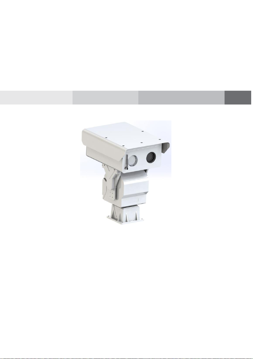
Bi-Spectral PTZ Network Camera
User Manual
Issue
V1.0
Date
2019-04-08


Bi-Spectral PTZ Network Camera
User Manual
Precautions
Issue V1.0 (2019-04-08) i
Precautions
Symbol
Description
It alerts you to fatal dangers which, if not avoided, may
cause deaths or severe injuries.
It alerts you to moderate dangers which, if not avoided,
may cause minor or moderate injuries.
It alerts you to risks. Neglect of these risks may cause
device damage, data loss, device performance
deterioration, or unpredictable results.
It provides a tip that may help you resolve problems or
save time.
It provides additional information.
Fully understand this document before using this device, and strictly observe rules in
this document when using this device. If you install this device in public places,
provide the tip "You have entered the area of electronic surveillance" in an eyecatching place. Failure to correctly use electrical products may cause fire and severe
injuries. To prevent accidents, carefully read the following context:
Symbols
This document may contain the following symbols whose meanings are described
accordingly.
Precautions
To prevent electric shocks or other dangers, keep power plugs dry and clean.
Strictly observe installation requirements when installing the device. The
manufacturer shall not be held responsible for device damage caused by users' nonconformance to these requirements.

Overview
Bi-Spectral PTZ Network Camera
User Manual
ii Issue V1.0 (2019-04-08)
Strictly conform to local electrical safety standards and use power adapters that are
marked with the LPS standard when installing and using this device. Otherwise,
this device may be damaged.
Use accessories delivered with this device. The voltage must meet input voltage
requirements for this device.
If this device is installed in places with unsteady voltage, ground this device to
discharge high energy such as electrical surges in order to prevent the power supply
from burning out.
When this device is in use, ensure that no water or any liquid flows into the device.
If water or liquid unexpectedly flows into the device, immediately power off the
device and disconnect all cables (such as power cables and network cables) from
this device.
Do not expose the thermal imaging camera or unpacked product to extremely
strong radiation sources, such as the sun, laser, or arc welding machine, regardless
of whether the device is being electrified or not; do not put the camera close to high
thermal objects such as the sunlight; otherwise, the precision of the camera may be
affected and even the detector inside the camera may suffer a permanent damage.
If this device is installed in places where thunder and lightning frequently occur,
ground the device nearby to discharge high energy such as thunder strikes in order
to prevent device damage.
Unless otherwise specified, do not use the camera in a temperature lower than 10°C (+14°F) or higher than +50°C (+122°F). Too-high or too-low temperature
may cause image display anomaly of the camera and the camera will be damaged if
it is working under such a condition for a long time.
If the camera is installed outdoors, avoid direct sunlight at dawn and dusk on the
camera lens and install a sunshield with frontal and rear positions adjusted
according to the sunlight angle.
Avoid heavy loads, intensive shakes, and soaking to prevent damages during
transportation and storage. The warranty does not cover any device damage that is
caused during secondary packaging and transportation after the original packaging
is taken apart.
Protect this device from fall-down and intensive strikes, keep the device away from
magnetic field interference, and do not install the device in places with shaking
surfaces or under shocks.
Clean the device with a soft dry cloth. For stubborn dirt, dip the cloth into slight
neutral cleanser, gently wipe the dirt with the cloth, and then dry the device.
Since the camera lens is painted with a durable coating material, it adapts to
outdoor environment. The lens must be cleaned regularly. If the image quality is
reduced or excessive dirt is deposited on the lens, clean the lens in a timely manner.
In sandy (in desert) or corrosive (on sea) environment, use the camera with caution;
improper use may cause the coating to peel off.

Bi-Spectral PTZ Network Camera
User Manual
Precautions
Issue V1.0 (2019-04-08) iii
Do not jam the ventilation opening. Follow the installation instructions provided in
this document when installing the device.
Keep the device away from heat sources such as radiators, electric heaters, or other
heat equipment.
Keep the device away from moist, dusty, extremely hot or cold places, or places
with strong electric radiation.
If the device is installed outdoors, take insect- and moisture-proof measures to
avoid circuit board corrosion that can affect monitoring.
Remove the power plug if the device is idle for a long time.
Before unpacking, check whether the fragile sticker is damaged. If the fragile
sticker is damaged, contact customer services or sales personnel. The manufacturer
shall not be held responsible for any artificial damage of the fragile sticker.
Special Announcement
All complete products sold by the manufacturer are delivered along with nameplates,
operation instructions, and accessories after strict inspection. The manufacturer shall
not be held responsible for counterfeit products.
This manual may contain misprints, technology information that is not accurate enough,
or product function and operation description that is slightly inconsistent with the
actual product. The manufacturer will update this manual according to product function
enhancement or changes and regularly update the software and hardware described in
this manual. Update information will be added to new versions of this manual without
prior notice.
This manual is only for reference and does not ensure that the information is totally
consistent with the actual product. For consistency, see the actual product.

Overview
Bi-Spectral PTZ Network Camera
User Manual
4 Issue V1.0 (2019-04-08)
Contents
Precautions .................................................................................................................... i
1 Overview ................................................................................................................... 7
1.1 Principle of Thermal Imaging and Advantages .............................................................. 7
1.2 Product Introduction ....................................................................................................... 7
1.2.1 Function ............................................................................................................. 8
1.2.2 Product Features ................................................................................................. 8
1.3 Description of PTZ cable ............................................................................................... 9
1.3.1 Aviation Power Supply and Network Cable of Twenty-six Cores ...................... 9
1.3.2 Aviation Alarm Cable of Twenty-Six Cores ..................................................... 10
2 Device Dimensions ............................................................................................... 13
3 Device Installation ................................................................................................. 14
3.1 Installation Method ...................................................................................................... 14
3.2 Device Installation ........................................................................................................ 14
3.2.1 Installation of Basic Requirements ................................................................... 14
3.2.2 Basic Installation Tool ...................................................................................... 14
3.2.3 Installation Space and Installation Strength ..................................................... 15
3.2.4 Definition of Installation Wiring Harness ........................................................ 15
4 Quick Configuration ............................................................................................. 17
4.1 Thermal Web ................................ ................................ ................................ ................ 17
4.1.1 Login and Logout ............................................................................................. 17
4.1.2 Main Page Layout ............................................................................................ 18
4.1.3 Change the Password ....................................................................................... 19
4.1.4 Browse Video ................................................................................................... 20
4.1.5 Install Plugins ................................................................................................... 22
4.1.6 Set Local Network Parameters ......................................................................... 22
4.1.7 Thermal Settings .............................................................................................. 25
4.1.7.1 Temperature Parameters .............................................................. 25
4.1.7.2 Temperature Area ........................................................................ 27
4.1.7.3 Schedule Linkage ........................................................................ 31
4.1.7.4 Bad Point Check .......................................................................... 32

Bi-Spectral PTZ Network Camera
User Manual
Overview
Issue V1.0 (2019-04-08) 5
4.2 Visible-light Web .......................................................................................................... 33
4.2.1 Login and Logout ............................................................................................. 33
4.2.2 Main Page Layout ............................................................................................ 34
4.2.3 Change the Password ....................................................................................... 36
4.2.4 Browse Video ................................................................................................... 37
4.2.5 Set Local Network Parameters ......................................................................... 39
5 Thermal Parameter Configuration ...................................................................... 43
5.1 Access the Sensor Setting Interface .............................................................................. 43
5.2 Sensor Setting Parameter .............................................................................................. 44
5.2.1 Time Segment .................................................................................................. 44
5.2.2 Image Setting ................................................................................................... 44
5.2.3 Scene ................................................................................................................ 46
5.2.4 Set Psecudocolor .............................................................................................. 46
5.2.5 FFC Control ..................................................................................................... 47
5.2.6 Noise Reduction ............................................................................................... 49
5.2.7 Enhance Image ................................................................................................. 50
6 Visible-light Parameter Configuration .............................................................. 53
6.1 Access the Sensor Interface .......................................................................................... 53
6.2 Sensor Setting Parameter description ........................................................................... 53
6.2.1 Time Segment .................................................................................................. 53
6.2.2 Image Adjust .................................................................................................... 54
6.2.3 Scene Mode ...................................................................................................... 55
6.2.4 Exposure .......................................................................................................... 57
6.2.5 WB Setting ....................................................................................................... 58
6.2.6 Daynight ........................................................................................................... 60
6.2.7 Noise Reduction ............................................................................................... 62
6.2.8 Enhance Image ................................................................................................. 63
6.2.9 Zoom Focus ..................................................................................................... 65
7 PTZ Function Application .................................................................................... 67
7.1 PTZ Control function ................................................................................................... 67
7.2 PTZ configuration ........................................................................................................ 68
7.2.1 PTZ Setting ...................................................................................................... 68
7.2.2 Configure and Apply Preset ............................................................................. 69
7.2.3 Configure and Apply Track .............................................................................. 69
7.2.4 Configure and Apply Scan ............................................................................... 70
7.2.5 Configure and Apply Tour ................................................................................ 71
7.2.6 Configure and Applye Idle ............................................................................... 72
7.2.7 Configure North ............................................................................................... 73

Overview
Bi-Spectral PTZ Network Camera
User Manual
6 Issue V1.0 (2019-04-08)
7.2.8 Configure Timer ............................................................................................... 74
7.2.9 Configure Extension......................................................................................... 75
8 Technical Specifications ....................................................................................... 76
A Troubleshooting.................................................................................................... 80
B Common Emission Rate ....................................................................................... 83

Bi-Spectral PTZ Network Camera
User Manual
Overview
Issue V1.0 (2019-04-08) 7
1 Overview
1.1 Principle of Thermal Imaging and Advantages
Any object with temperature higher than the absolute zero (-273.15°F) will emit
infrared (IR) ray, even though it does not emit light. The IR ray is also called thermal
radiation. IR rays emitted by objects with different temperatures can be absorbed by the
detector to reflect temperature change and thus generate an electric effect. The electric
signal is amplified and processed to produce a thermal image that corresponds to the
thermal distribution of the object surface. This is the process of thermal imaging.
Adapt to any environment
Traditional cameras rely on natural or environmental light to shoot images, but this
IR thermal imaging camera relies on the IR energy radiated by an object itself to
form an image, not requiring any light. The IR thermal imaging camera is
applicable to any environment and not affected by light strength. It can detect and
identify any camouflage and concealed object both in daytime or nighttime,
implementing round-the-clock monitoring.
Monitor the temperature field with object energy distributed
The IR thermal imaging camera can show the temperature field of an object,
converting the invisible surface temperature distribution situation to a visible
thermal image that reflects the surface temperature distribution situation of the
object. By this monitoring, users can discover temperature anomaly in a timely
manner and take precautionary measures to avoid any risk that may be caused by
the anomaly, for example, a fire.
Boast cloud penetration capability
Visible light and near IR ray will be absorbed by the air, cloud and smoke, but they
are transparent to IR ray of the 3~5 μm Medium Wavelength Infrared (MWIR)
region and 8~14 μm Long Wavelength Infrared (LWIR) region. Traditional
cameras cannot shoot clear images under cloudy environment, but the IR thermal
imaging camera can penetrate the cloud and smoke to shoot clear images.
1.2 Product Introduction
Bi-Spectral PTZ Network Camera, the whole machine shell and the base are all
made of high strength aluminum alloy material with comprehensive function and
high stability. Can adapt to a variety of bad environment, heavy load can reach
more than 50kg and run smoothly. This series has 360°continuous rotation,
automatic scanning, automatic cruise and other functions, suitable for large areas of

Overview
Bi-Spectral PTZ Network Camera
User Manual
8 Issue V1.0 (2019-04-08)
monitoring, can be widely used in airports, stations, urban roads, traffic survey and
monitoring, forest fire prevention, the high and heavy equipment rotary control and
other important area.
1.2.1 Function
To support a variety of scanning methods, such as cruise scan, pattern scanning, etc.
It supports the function of power off memory and automatically returns to the
monitoring scene before power off.
Support network signal and analog signal double output, cloud platform control
classification operation.
The double helix structure of worm gear and worm drive, the electronic image
stabilization, and mechanical locking design, power self-locking function.
Horizontal continuous rotation 360°,vertically +40° ~- 75° rotating, horizontal
velocity is 0.01°~60 °/S, vertical speed of 0.01° ~ 30°/S
Support proportion variable times function, rotation speed adjusted automatically
according to the lens change multiple times.
Support watch features preset point/figure/cruise can stay idle scan specified
Automatic call after time (including the idle state entered after power).
1.2.2 Product Features
Outdoor intelligent variable speed PTZ, the fuselage selection of high strength
aluminum alloy material, exterior design can resist strong winds, smooth operation,
high precision.
Products using high-precision stepper motor and precision worm gear drive
combination, power can be self-locking.
Support a variety of lens preset function, zoom adaptive function, the rotation
speed can be automatically adjusted according to the lens zoom factor.
Powerful, with preset, cruise, line sweep, keep watch and other functions.
Visual pitch angle range, monitoring a wide range of horizontal speed up to 6°/ s.
Equipment has its own automatic heating system, low temperature automatically
start heating function, to ensure that products can be applied to cold areas.
Network transmission signal can reach 100Mbps.
Device supports RS485 / RS422 communication interface, you can remotely
upgrade the device program, easy to maintain.
Power failure memory function, accidental power after re-power, the memory of
the last running state, can be restored to power before running state.
Bi-Spectral PTZ Network Camera
User Manual
Overview
Issue V1.0 (2019-04-08) 9
1.3 Description of PTZ cable
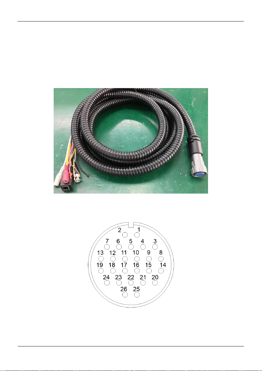
1.3.1 Aviation Power Supply and Network Cable of Twenty-six
Cores
Aviation power supply and network cable of twenty-six cores is shown as Figure 1-1 &
Figure 1-2, and the description is shown in Table 1-1.
Figure 1-1 Aviation power supply and network cable of twenty-six cores
Figure 1-2 Definition of twenty-six cores

Overview
Bi-Spectral PTZ Network Camera
User Manual
10 Issue V1.0 (2019-04-08)
Table 1-1 Description of twenty-six cores
SN
Name
Description
1
DC36V-
Black (Thick)
2
DC36V+
Red (Thick)
3
DC36V-
Black (Thick)
4
DC36V-
Black (Thick)
5
Alarm_OUT1
Red (Thin)
6
DC36V+
Red (Thick)
7
DC36V+
Red (Thick)
8
Audio_IN(G)
Audio masking
9
Audio_IN
Audio Core
10
Alarm_OUT1
Black (Thin)
11
Alarm_OUT3
Blue
12
Alarm_OUT3
Pink
13
Alarm_OUT4
White
14
Audio_OUT(G)
Audio masking
15
Audio_OUT
Audio Core
16
Video
Video Core
17
Video (G)
Video masking
18
Alarm_OUT2
White and Orange
19
Alarm_OUT4
Green
20
RS485A
Orange (Thick)
21
RS485B
Yellow (Thick)
22
ETHTX+
White and Orange
23
ETHTX-
Orange
24
Alarm_OUT2
White and Yellow
25
ETHRX+
White and Green
26
ETHRX-
Green
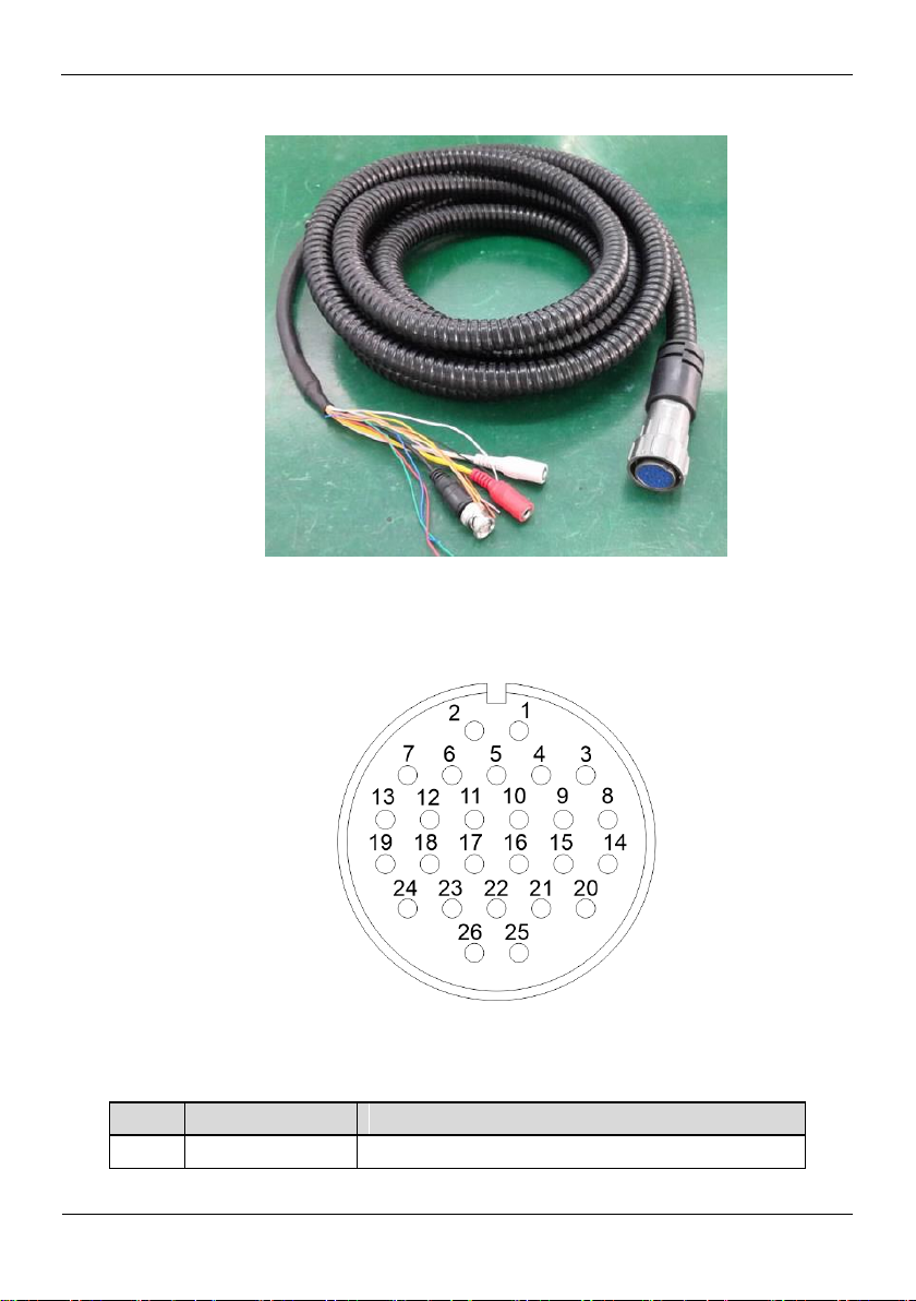
1.3.2 Aviation Alarm Cable of Twenty-Six Cores
Aviation alarm cable of twenty-six cores is shown as Figure 1-3& Figure 1-4, and the
description is shown in Table 1-2.
Bi-Spectral PTZ Network Camera
User Manual
Overview
Issue V1.0 (2019-04-08) 11
Figure 1-3 Aviation power supply cable of twenty-six cores
SN
Name
Description
1
Reserved core
Blank
Figure 1-4 Definition of twenty-six cores
Table 1-2 Description of twelve cores

Overview
Bi-Spectral PTZ Network Camera
User Manual
12 Issue V1.0 (2019-04-08)
SN
Name
Description
2
Reserved core
Blank
3
Reserved core
Blank
4
Reserved core
Blank
5
Reserved core
Ground
6
Reserved core
Blank
7
Reserved core
Blank
8
Reserved core
Ground
9
Reserved core
Ground
10
Reserved core
Blank
11
Alarm_IN1
White
12
Alarm_IN2
White and Orange
13
Alarm_IN3
Blue
14
Audio_IN(G)
Audio masking
15
Audio_IN
Audio Core
16
Video
Video Core
17
Video(G)
Video masking
18
Audio_OUT
Audio Core
19
Audio_OUT(G)
Audio masking
20
Alarm_IN4
Pink
21
Alarm_IN5
Red (Thin)
22
Alarm_IN6
White and Yellow
23
Alarm_IN7
Blank
24
Alarm_IN8
Yellow (Thick)
25
Alarm_IN9
Orange (Thick)
26
Alarm_G
Black (Thick)
----End

Bi-Spectral PTZ Network Camera
User Manual
Device Dimensions
Issue V1.0 (2019-04-08) 13
2 Device Dimensions
Figure 2-1 shows the dimensions of the Bi-Spectral PTZ Network Camera.
Figure 2-1 Dimensions (unit: mm)
Device Installation
Bi-Spectral PTZ Network Camera
User Manual
14 Issue V1.0 (2019-04-08)
3.1 Installation Method
Name
Quantity
Remarks
13mm wrench
1
For mounting fixtures and mounting
brackets
14mm sleeve
1
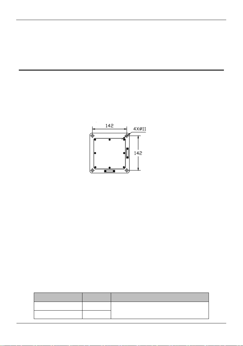
Bi-Spectral PTZ Network Camera can be installed on camera base.
Figure 3-1 shows the base dimensions of PTZ camera.
Figure 3-1 Base dimensions of PTZ camera (unit: mm)
3 Device Installation
3.2 Device Installation
3.2.1 Installation of Basic Requirements
Installation site and environment to meet the technical parameters mentioned in the
requirements, the installation staff should have been fully read and read the contents of
this manual, with the appropriate system installation qualification and maintenance
work qualification certificate.
3.2.2 Basic Installation Tool
Commonly used engineering wiring and equipment installation tools, please install the
equipment before the preparation is complete.
Table 3-1 shows the installation tools list.
Table 3-1 Installation tools

Bi-Spectral PTZ Network Camera
User Manual
Device Installation
Issue V1.0 (2019-04-08) 15
COLOR
Function define
Remark
BNC
Video
Optional
Red
DC36V+
Black
DC36V-
RJ45
Network cable
Orange
RS422 TX+
Yellow
RS422 TX-
Red
RS422 RX+
Blue
RS422 RX-
Yellow & Green
GND
Cross
screwdriver(big)
1
For common construction
Cross
screwdriver(small)
1
Used to disassemble the DIP cover to
adjust the device communication
parameters
Inside the hex
wrench
1 set
Used for disassembly of pan / tilt pallet and
shield connection
Word screwdriver
(small)
1
to secure the wiring harness connection
terminals
Wire strippers
1
Stripping
3.2.3 Installation Space and Installation Strength
Under normal circumstances, this device needs to be equipped with a protective cover
or other overhead items, please confirm the installation location can accommodate this
product and the equipment and installation of the structure of the space. To confirm the
installation of the wall, the carrying capacity of the bracket can reach 4 times the safety
of the entire equipment weight.
3.2.4 Definition of Installation Wiring Harness
The bottom line includes power line, network cable, RS422, geodetic line, video line,
and according to the demand, there are various types of outgoing line. The details need
to be controlled according to the line signature of each device.
Table 3-2 shows Definition of installation wiring harness.
Table 3-2 Definition of installation wiring harness
In order to prevent lightning strikes, the grounding wire (yellow-green wire) in the cable
outlet base must be grounded reliably and the grounding resistance should be <4Ω.

Device Installation
Bi-Spectral PTZ Network Camera
User Manual
16 Issue V1.0 (2019-04-08)
----End
Bi-Spectral PTZ Network Camera
User Manual
Quick Configuration
17 Issue V1.0 (2019-04-08)
4 Quick Configuration
4.1 Thermal Web
4.1.1 Login and Logout
You must use Internet Explorer 8 or a later version to access the web management
system; otherwise, some functions may be unavailable.
Login system
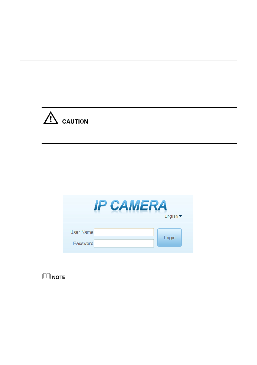
Step 1 Open the Internet Explorer, enter the IP address of IP camera (default value:
192.168.0.121) in the address box, and press Enter.
The login page is displayed, as shown in Figure 4-1.
Figure 4-1 Login page
Step 2 Input the User name and password.
The default user name is admin. The default password is admin. Change the password
when you log in the system for first time to ensure system security.
You can change the system display language on the login page.
Step 3 Click Login.
The main page is displayed.
----End
Quick Configuration
Bi-Spectral PTZ Network Camera
User Manual
18 Issue V1.0 (2019-04-08)
logout
1
2
3
4
5
6
7 8 9
101112
13
14
No.
Element
Description
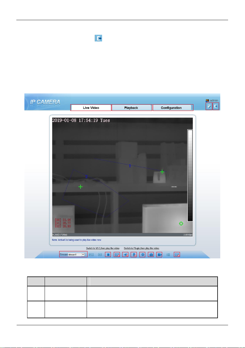
1
Real-time video
area
Real-time videos are played in this area. You can also set
sensor parameters.
2
Playback
You can query the playback videos in this area.
NOTE
To logout of system, click in the upper right corner of the main page, the login page
is display after you log out of the system.
4.1.2 Main Page Layout
On the main page, you can view real-time video, set parameter, Video parameter, Video
control, PTZ control, PTZ Configure and log out of the system. Figure 4-2 is shown the
main page layout. Table 4-1 lists the elements on the main page layout.
Figure 4-2 Main page layout
Table 4-1 Elements on the main page
Bi-Spectral PTZ Network Camera
User Manual
Quick Configuration
19 Issue V1.0 (2019-04-08)
No.
Element
Description
Only when the SD card or NAS have videos that user can query
the playback videos.
3
Device
configuration
You can choose a menu to set device parameters,
including the device information, audio and video streams,
alarm setting, and privacy mask function.
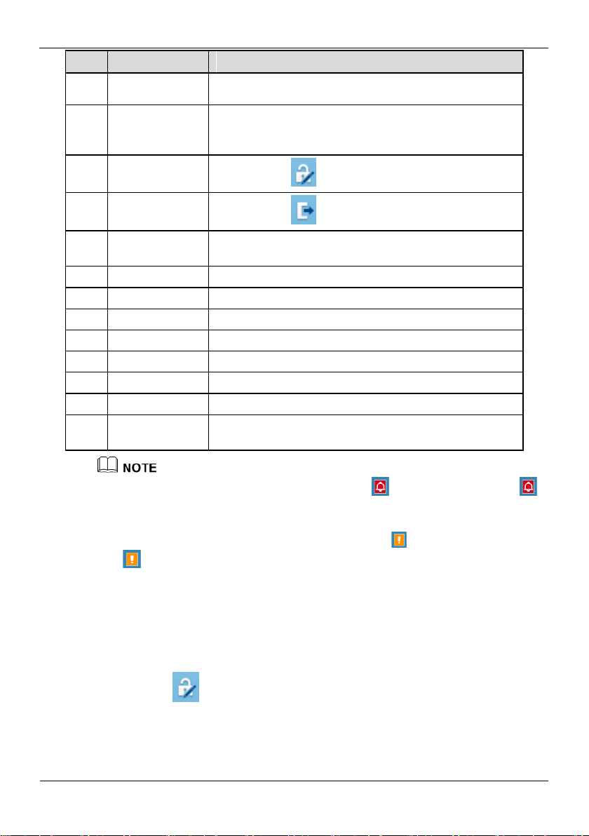
4
Change
password
You can click to change the password.
5
Sign Out
You can click to return to the login page.
6
Stream
Three are three streams. Choose one type from drop-down
list.
7
Pause/Start
Close live video or play live video.
8
Live/Smooth
Switch image quality.
9
Audio
Open or close audio.
10
Interphone
Open or close interphone.
11
Sensor setting
Click the icon, it will access to sensor setting.
12
Snapshot
Click the icon, it will snapshot.
13
Local record
Click the icon, it will record video and save.
14
Intelligent
analysis
Open or close intelligent analysis.
1. When the device generates an alarm, the alarm icon is displayed. You can click
to view the alarm information. When the device accepts an alarm signal, the alarm icon will
display within 10s in the web management system.
2. When the device encounters an exception, the fault icon is displayed. You can click
to view the fault information.
----End
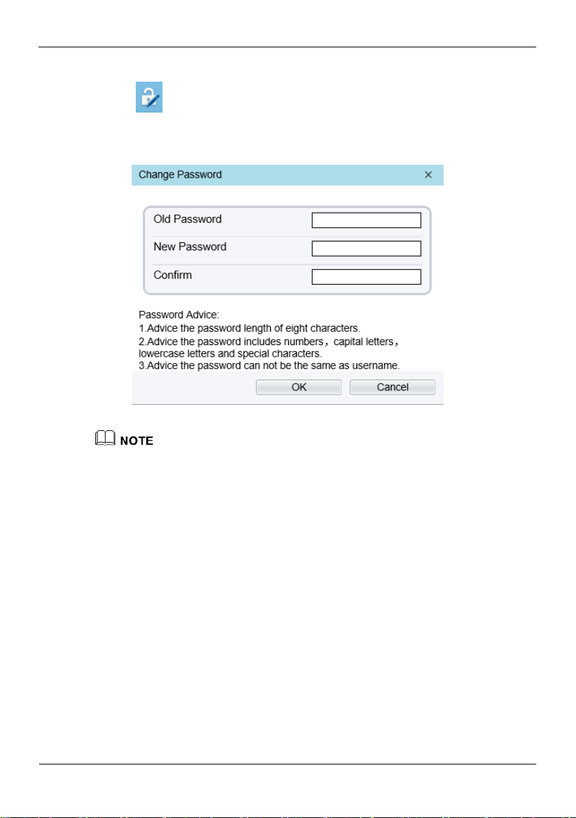
4.1.3 Change the Password
Description
You can click to change the password for logging in to the system.
Quick Configuration
Bi-Spectral PTZ Network Camera
User Manual
20 Issue V1.0 (2019-04-08)
Procedure
Step 1 Click in the upper right corner of the main page.
The Change Password dialog box is displayed, as shown in Figure 4-3.
Figure 4-3 Modify Password dialog box
The change password page will be displayed if you don’t change the default password when
you login the system for the first time.
Step 2 Enter the old password, new password, and confirmation password.
Step 3 Click OK.
If the message "Change own password success" is displayed, the password is
successfully changed. If the password fails to be changed, the cause is displayed. (For
example, the new password length couldn’t be less than eight.)
Step 4 Click OK.
The login page is displayed.
----End
4.1.4 Browse Video
User can browse the real-time video in the web management system.
Preparation
To ensure the real-time video can be play properly, you must perform the following
operation when you log in to the web for the first time:

Bi-Spectral PTZ Network Camera
User Manual
Quick Configuration
21 Issue V1.0 (2019-04-08)
Step 1 Open the Internet Explorer. Choose Tools > Internet options > Security > Trusted
sites > Sites.
In the display dialog box, click Add, as shown in Figure 4-4.
Figure 4-4 Adding the a trusted site
Step 2 In the Internet Explorer, choose Tool > Internet Options > Security > Customer
level, and set Download unsigned ActiveX control and initialize and script ActiveX
controls not marked as safe for scripting under ActiveX controls and plug-ins to Enable,
as shown in Figure 4-5.
Figure 4-5 Configuring ActiveX control and plug-ins
Quick Configuration
Bi-Spectral PTZ Network Camera
User Manual
22 Issue V1.0 (2019-04-08)
Step 3 Download and install the player control as prompted.
The login page is display when the control is loaded.
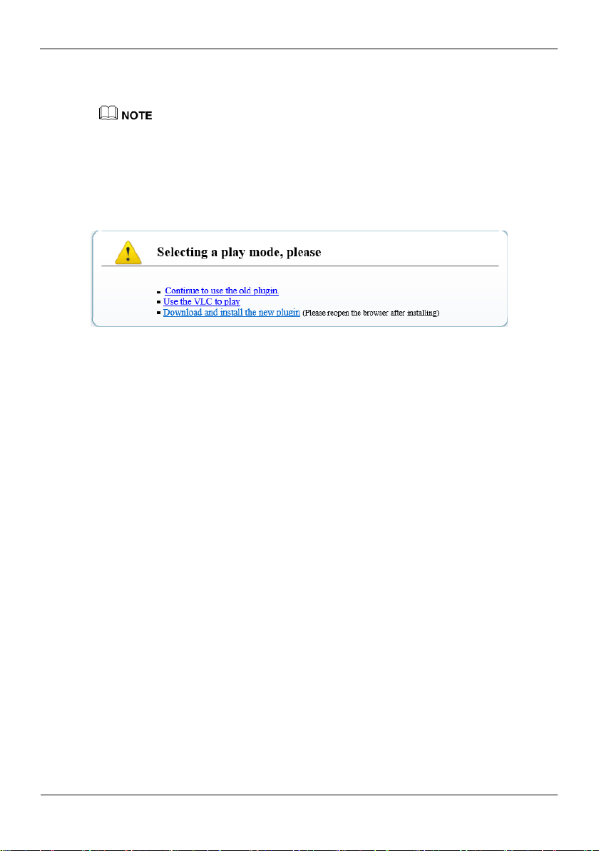
4.1.5 Install Plugins
You will be prompted with a message “Download and install the new plugin” as shown
in Figure 4-6 when you log in to the web management system for the first time.
Figure 4-6 Download the plugin page
Procedure
Step 1 Click the message, download and install the plugin follow the prompts.
Step 2 Reopen the browser after installation.
----End
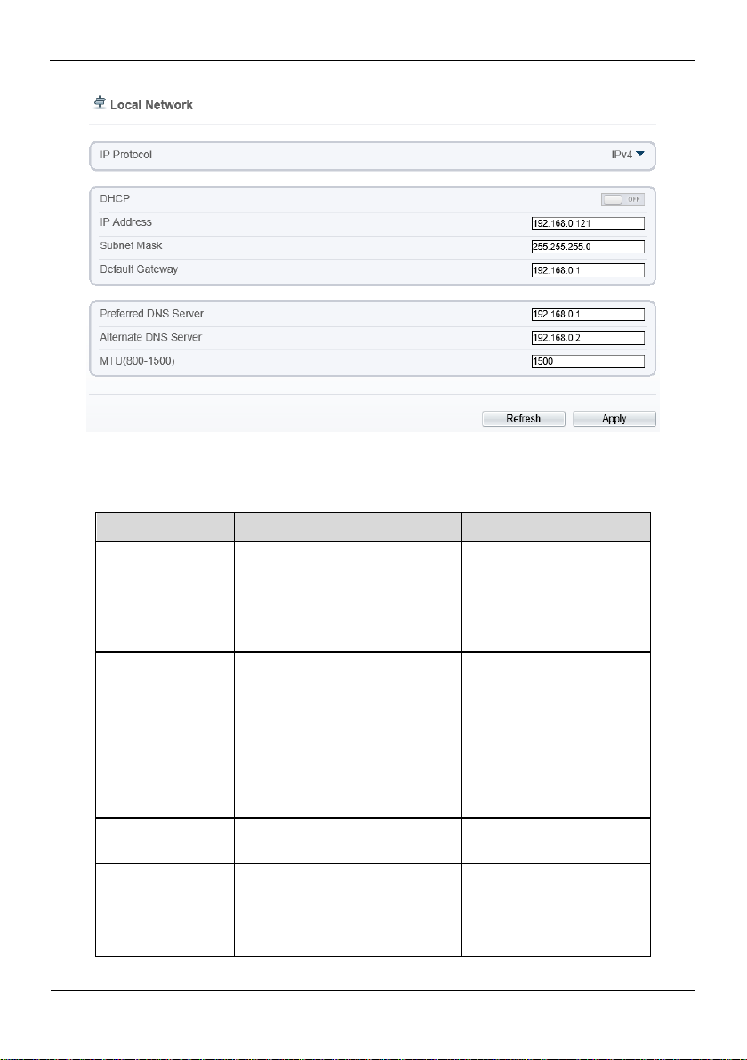
4.1.6 Set Local Network Parameters
Description
Local network parameters include:
IP protocol
IP address
Subnet mask
Default gateway
Dynamic Host Configuration Protocol (DHCP)
Preferred Domain Name System (DNS) server
Alternate DNS server
MTU
Procedure
Step 1 Choose Configuration > Device >Local Network.
The Local Network page is displayed, as shown in Figure 4-7.
Bi-Spectral PTZ Network Camera
User Manual
Quick Configuration
23 Issue V1.0 (2019-04-08)
Figure 4-7 Local Network page
Parameter
Description
Setting
IP Protocol
IPv4 is the IP protocol that uses
an address length of 32 bits.
[Setting method]
Select a value from the
drop-down list box.
[Default value]
IPv4
DHCP
The device automatically
obtains the IP address from the
DHCP server.
[Setting method]
Click the option button.
NOTE
To query the current IP
address of the device, you
must query it on the
platform based on the
device name.
DHCP IP
IP address that the DHCP server
assigned to the device.
N/A
IP Address
Device IP address that can be
set as required.
[Setting method]
Enter a value manually.
[Default value]
192.168.0.120
Step 2 Set the parameters according to Table 4-2.
Table 4-2 Local network parameters

Quick Configuration
Bi-Spectral PTZ Network Camera
User Manual
24 Issue V1.0 (2019-04-08)
Parameter
Description
Setting
Subnet Mask
Subnet mask of the network
adapter.
[Setting method]
Enter a value manually.
[Default value]
255.255.255.0
Default Gateway
This parameter must be set if
the client accesses the device
through a gateway.
[Setting method]
Enter a value manually.
[Default value]
192.168.0.1
Preferred DNS
Server
IP address of a DNS server.
[Setting method]
Enter a value manually.
[Default value]
192.168.0.1
Alternate DNS
Server
IP address of a domain server.
If the preferred DNS server is
faulty, the device uses the
alternate DNS server to resolve
domain names.
[Setting method]
Enter a value manually.
[Default value]
192.168.0.2
MTU
Set the maximum value of
network transmission data
packets.
[Setting method]
Enter a value manually.
NOTE
The MTU value is range
from 800 to 1500, the
default value is 1500,
Please do not change it
arbitrarily.
Step 3 Click OK.
If the message "Apply success" is displayed, click OK. The system saves the
settings. The message "Set network pram’s success, Please login system again" is
displayed. Use the new IP address to log in to the web management system.
If the message "Invalid IP Address", "Invalid Subnet Mask", "Invalid default
gateway", "Invalid primary DNS", or "Invalid space DNS" is displayed, set the
parameters correctly.
If you set only the Subnet Mask, Default Gateway, Preferred DNS Server, and
Alternate DNS Server parameters, you do not need to log in to the system again.
You can click Reset to set the parameters again if required.
----End

Bi-Spectral PTZ Network Camera
User Manual
Quick Configuration
25 Issue V1.0 (2019-04-08)
4.1.7 Thermal Settings
Parameter
Description
Setting
Temperature Unit
Celsius and Fahrenheit
temperature units are available.
[Setting method]
Select a value from the
drop-down list box.
[Default value]
Celsius
Ambient
Temperature
The ambient temperature of
camera. It is set when ambient
is outside.
[Setting method]
Enter a value manually.
4.1.7.1 Temperature Parameters
Temperature parameters include: temperature unit, ambient type, ambient temperature,
cavity temperature, correctional coefficient and area temperature display mode.
Operation Procedure
Step 1 Choose Configuration >Thermal >Temperature Parameters.
The Temperature Parameters page is displayed, as shown in Figure 4-8.
Figure 4-8 Temperature Parameters interface
Step 2 Set the parameters according to Table 4-3.
Table 4-3 Temperature parameters

Quick Configuration
Bi-Spectral PTZ Network Camera
User Manual
26 Issue V1.0 (2019-04-08)
Parameter
Description
Setting
Cavity
Temperature
The cavity temperature of
camera.
N/A
Correction
Coefficient
Correction coefficient is refer to
the deviation of measured
object temperature and
actual temperature.
For example:
1. The measured object
temperature is 30, and actual
temperature is 37, so the
correction coefficient should be
7.
2. The measured object
temperature is 37, and actual
temperature is 30, so the
correction coefficient should be
-7.
[Setting method]
Enter a value manually.
[Default value]
0.00
Area Temperature
Display Mode
The display position of
temperature information on the
live-video image.
[Setting method]
Select a value from the
drop-down list box.
[Default value]
Low left
Custom Colors
Enable to custom the color,
there are nine colors chosen.
[Setting method]
Enable or disable
[Default value]
disable
Area Temperature
Type
There are three types of area
temperature.
[Setting method]
Select a value from the
drop-down list box.
[Default value]
Highest Temperature
Measure Mode
There are two types measure
modes.
[Setting method]
Select a value from the
drop-down list box.
[Default value]
General
Display Alarm
Area
N/A
[Setting method]
Enable or disable
[Default value]
disable

Bi-Spectral PTZ Network Camera
User Manual
Quick Configuration
27 Issue V1.0 (2019-04-08)
Parameter
Description
Setting
Area Alarm
Interval
N/A
[Setting method]
Enter a value manually
ranges from 1 to 1800.
[Default value]
10
Step 3 Click Apply.
The message "Apply success" is displayed, the system saves the settings.
----End
4.1.7.2 Temperature Area
Operation Procedure
Step 1 Choose Configuration >Thermal >Temperature Area.
The Temperature Area page is displayed, as shown in Figure 4-9

Quick Configuration
Bi-Spectral PTZ Network Camera
User Manual
28 Issue V1.0 (2019-04-08)
Figure 4-9 Temperature area and alarm configuration
Parameter
Description
Setting
Channel
N/A
[Setting method]
Select a value from the
drop-down list box.
[Default value]
1
Measure Mode
Set at temperature parameter
interface.
N/A
Enable
Tick to enable alarm areas.
N/A
ID
It ranges from 0 to19.
N/A
Name
Area name of temperature area.
[Setting method]
Enter a value manually.
Step 2 Set the parameters according to Table 4-4
Table 4-4 Temperature area and alarm configuration

Bi-Spectral PTZ Network Camera
User Manual
Quick Configuration
29 Issue V1.0 (2019-04-08)
Parameter
Description
Setting
Type
Type of temperature area.
ID 0 is default rectangle area,
which is full screen.
[Setting method]
Select a value from the
drop-down list box.
[Default value]
Rectangle/Point
Alarm Type
Threshold alarm and
Temperature difference alarm
are available for alarm type.
[Setting method]
Select a value from the
drop-down list box.
[Default value]
Threshold alarm
Warning Value
Camera will warn when the
surveillance object temperature
reaches the warning value.
[Setting method]
Enter a value manually.
[Default value]
48.00
Alarm Value
Camera will alarm when the
surveillance object temperature
reaches the alarm value.
[Setting method]
Enter a value manually.
[Default value]
50.00
Emission Rate
The emission rate is the
capability of an object to emit
or absorb energy.
The emission rate should be set
only when the target is special
material.
The emission rate list refers to
B Common Emission Rate
[Setting method]
Enter a value manually.
[Default value]
0.95
Distance(M)
The distance between camera
and target.
[Setting method]
Enter a value manually.
[Default value]
15
Enter actual distance when
the distance between
camera and target is less
than 15m.Enter 15 when
the distance between
camera and target is
great than or equal to 15m.
Alarm
Open or close the alarm output
and linkage of area.
[Setting method]
Tick the alarm areas

Quick Configuration
Bi-Spectral PTZ Network Camera
User Manual
30 Issue V1.0 (2019-04-08)
Step 3 Set temperature area.
1. Tick an area ID.
2. Select type from drop-list.
3. Press and hold the left mouse button, and drag in the video area to draw a
temperature area, as shown in Figure 4-10. Right-click to finish the area selected.
Figure 4-10 Temperature Area Setting Interface
4. Click Apply, the message “Apply success” is displayed, the temperature area is set
successfully.
Delete a temperature area:
5. Select an area ID.
6. Click the temperature area and right-click.
7. Remove the tick of area ID.
8. Click Apply, the message “Apply success” is displayed, the temperature area is
deleted successfully.
Step 4 Click Apply.
The message "Apply success" is displayed, the system saves the settings.
----End

Bi-Spectral PTZ Network Camera
User Manual
Quick Configuration
31 Issue V1.0 (2019-04-08)
4.1.7.3 Schedule Linkage
NOTE
Operation Procedure
Step 1 Choose Configuration >Thermal > Schedule Linkage
The Schedule Linkage page is displayed, as shown in Figure 4-11.
Figure 4-11 Schedule Linkage
Step 2 Tick the output channel.
Step 3 Enable “Alarm Record”, “SMTP”,”FTP” button.
Step 4 Set schedule linkage.
Method 1:Click left mouse button to select any time point within 0:00-24:00 from
Monday to Sunday as shown in Figure 4-11.
Method 2:Hold down the left mouse button, drag and release mouse to select the
alarm time within 0:00-24:00 from Sunday to Saturday.
When you select time by dragging the cursor, the cursor cannot be moved out of the
time area. Otherwise, no time can be selected.
Method 3:Click in the alarm time page to select the whole day or whole week.
Deleting alarm time: Click again or inverse selection to delete the selected alarm
time.
Step 5 Click Apply.
The message "Apply success" is displayed, the system saves the settings.

Quick Configuration
Bi-Spectral PTZ Network Camera
User Manual
32 Issue V1.0 (2019-04-08)
----End
Bad Point 1
Bad Point 2
4.1.7.4 Bad Point Check
Description
The points that can’t move when the environment or scenario change is bad point. You
can delete the bad point by bad point check function.
Procedure
Step 1 Choose Configuration >Thermal > Bad Point Check
The Bad Point Check page is displayed, as shown in Figure 4-12.
Figure 4-12 Bad Point Check
Step 2 Click the white point at image, click Apply to recover the bad point, as shown in
Figure 4-13

Bi-Spectral PTZ Network Camera
User Manual
Quick Configuration
33 Issue V1.0 (2019-04-08)
Figure 4-13 Recover bad point
Step 3 Click Reset to return the previous settings.
Step 4 Click Apply. The message "Apply success" is displayed, the system saves the settings.
----End
4.2 Visible-light Web
4.2.1 Login and Logout
You must use Internet Explorer 8 or a later version to access the web management
system; otherwise, some functions may be unavailable.

Quick Configuration
Bi-Spectral PTZ Network Camera
User Manual
34 Issue V1.0 (2019-04-08)
Login system
Step 1 Open Internet Explorer, enter the IP address of the IP camera (default value:
192.168.0.120) in the address box, and press Enter.
The login page is displayed, as shown in Figure 4-14.
Figure 4-14 Login page
Step 2 Enter the user name, and password.
The default user name is admin. The default password is admin.
Please change the password to ensure system security.
You can change the system display language on the login page.
Step 3 Click login.
The main page is displayed.
----End
Logout
To log out of the system, click in the upper right corner of the main page. The
login page is displayed after you log out of the system.
4.2.2 Main Page Layout
On the main page, you can view real-time videos, receive alarm and fault notifications,
set parameters, change the password, and log out of the system. Figure 4-15 shows the
main page layout. Table 4-5 describes the elements on the main page.

Bi-Spectral PTZ Network Camera
User Manual
Quick Configuration
35 Issue V1.0 (2019-04-08)
Figure 4-15 Main page layout
No.
Element
Description
1
Real-time video area
Real-time videos are played in this area. You
can also set sensor parameters.
2
Playback
You can query the playback videos in this area.
NOTE
Only when the SD card or NAS have videos that
you can query the playback videos.
3
Device configuration
You can choose a menu to set device
parameters, including the device information,
audio and video streams, alarm setting, and
privacy mask function.
4
Alarm icon
When the device generates an alarm, the alarm
icon is displayed. You can click to
view the alarm information.
NOTE
When the device accepts an alarm signal, the alarm
icon will display within 10s in the web
management system.
Table 4-5 Elements on the main page

Quick Configuration
Bi-Spectral PTZ Network Camera
User Manual
36 Issue V1.0 (2019-04-08)
No.
Element
Description
5
Fault icon
When the device encounters an exception, the
fault icon is displayed.
You can click to view the fault
information.
6
Change password
You can click to change the password.
7
Sign Out
You can click to return to the login page.
----End
4.2.3 Change the Password
Description
You can click to change the password for logging in to the system.
Procedure
Step 1 Click in the upper right corner of the main page.
The Change Password dialog box is displayed, as shown in Figure 4-16.

Bi-Spectral PTZ Network Camera
User Manual
Quick Configuration
37 Issue V1.0 (2019-04-08)
Figure 4-16 Modify Password dialog box
The change password page will be displayed if you don’t change the default password when
you login the system for the first time.
Step 2 Enter the old password, new password, and confirmation password.
Step 3 Click OK.
If the message "Change own password success" is displayed, the password is
successfully changed. If the password fails to be changed, the cause is displayed. (For
example, the new password length could not be less than eight.)
Step 4 Click OK.
The login page is displayed.
----End
4.2.4 Browse Video
User can browse the real-time video in the web management system.
Preparation
To ensure that real-time videos can be played properly, you must perform the
following operations when you log in to the web management system for the first time:
Step 1 Open Internet Explorer. Choose Tools > Internet Options > Security > Trusted
sites > Sites.
In the displayed dialog box, click Add, as shown in Figure 4-17.

Quick Configuration
Bi-Spectral PTZ Network Camera
User Manual
38 Issue V1.0 (2019-04-08)
Figure 4-17 Adding a trusted site
Step 2 In Internet Explorer, choose Tools > Internet Options > Security > Customer level,
and set Download unsigned ActiveX controls and Initialize and script ActiveX controls
not marked as safe for scripting under ActiveX controls and plug-ins to Enable, as
shown in Figure 4-18.
Figure 4-18 Configuring ActiveX controls and plug-ins

Bi-Spectral PTZ Network Camera
User Manual
Quick Configuration
39 Issue V1.0 (2019-04-08)
Step 3 Download and install the player control as prompted.
If the repair tips displayed when installing the control, please ignore the prompt, and
continue the installation, the login page is displayed when the control is loaded.
Download the right control in the Internet Explorer
Real-time video page pop-ups the message clicks to play live video with ActiveX
control to reduce latency.
Click the message, jump to download ActiveX control interface, once downloading is
complete, you can watch more fluent video screen.
Unable to display video picture, and need to download and install the control
Real-time video page pop-up the message click to download the latest version of
Flash Play live video and click to play video with ActiveX control to reduce latency.
Click the message click to play live video with ActiveX control to reduce latency,
jump download Adobe Flash Player Plugin control interface, once downloading is
complete, you can watch video screen.
Click the message click to download the latest version of Flash Play live video,
jump to download ActiveX control interface, once downloading is complete, you can
watch more fluent video screen.
In the Google, Firefox, or Safari browsers watch real-time video
Google, Firefox, and Safari browsers only support Adobe Flash Player Plugin to play
video. When Adobe Flash Plugin control version is too low, browser will automatically
clew you to download the latest control.
----End
4.2.5 Set Local Network Parameters
Description
Local network parameters include:
IP protocol
IP address
Subnet mask
Default gateway
Dynamic Host Configuration Protocol (DHCP)
Preferred Domain Name System (DNS) server
Alternate DNS server
MTU

Quick Configuration
Bi-Spectral PTZ Network Camera
User Manual
40 Issue V1.0 (2019-04-08)
Procedure
Parameter
Description
Setting
IP Protocol
IPv4 is the IP protocol that uses an
address length of 32 bits.
[Setting method]
Select a value from
the drop-down list
box.
[Default value]
IPv4
Step 1 Choose Configuration > Device > Local Network..
The Local Network page is displayed, as shown in Figure 4-19
Figure 4-19 Local Network page
Step 2 Set the parameters according to Table 4-6.
Table 4-6 Local network parameters

Bi-Spectral PTZ Network Camera
User Manual
Quick Configuration
41 Issue V1.0 (2019-04-08)
Parameter
Description
Setting
Obtain IP address
automatically
The device automatically obtains
the IP address from the DHCP
server.
[Setting method]
Click the button on
to enable DHCP.
NOTE
To query the current
IP address of the
device, you must
query it on the
platform based on
the device name.
DHCP IP
IP address that the DHCP server
assigned to the device.
N/A
IP Address
Device IP address that can be set as
required.
[Setting method]
Enter a value
manually.
[Default value]
192.168.0.120
Subnet Mask
Subnet mask of the network
adapter.
[Setting method]
Enter a value
manually.
[Default value]
255.255.255.0
Default Gateway
This parameter must be set if the
client accesses the device through a
gateway.
[Setting method]
Enter a value
manually.
[Default value]
192.168.0.1
Preferred DNS
Server
IP address of a DNS server.
[Setting method]
Enter a value
manually.
[Default value]
192.168.0.1
Alternate DNS
Server
IP address of a domain server.
If the preferred DNS server is
faulty, the device uses the alternate
DNS server to resolve domain
names.
[Setting method]
Enter a value
manually.
[Default value]
192.168.0.2

Quick Configuration
Bi-Spectral PTZ Network Camera
User Manual
42 Issue V1.0 (2019-04-08)
Parameter
Description
Setting
MTU(800-1500)
Set the maximum value of network
transmission data packets.
[Setting method]
Enter a value
manually.
NOTE
The MTU value is
range from 800 to
1500, the default
value is 1500,
Please do not
change it arbitrarily.
Step 3 Click Apply.
If the message "Apply succeed!" is displayed, click Confirm. The system saves the
settings. The message "Set network parameter success, Please login system again"
is displayed. Use the new IP address to log in to the web management system.
If the message "Invalid IP Address", "Invalid Subnet Mask", "Invalid default
gateway", "Invalid primary DNS", or "Invalid space DNS" is displayed, set the
parameters correctly.
----End

Bi-Spectral PTZ Network Camera
User Manual
Thermal Parameter Configuration
43 Issue V1.0 (2019-04-08)
5 Thermal Parameter Configuration
Parameter
Description
Full Screen
It enlarges and displays the image in full screen.
Sensor
Configure
It is used for configuring the parameter set of front-end images.
Zoom In/Out
It zooms in/out images by electronic means. This function may
also be used with the mouse wheel.
Open point
measurement
(Turn on the
mouse to
measure the
temperature)
Click this option to measure the target temperature that the
mouse moved.
5.1 Access the Sensor Setting Interface
Operation procedure:
Step 1 On the web interface or client interface, move the cursor to the real-time video page
and right-click on the page. A shortcut menu is displayed, as shown in Figure 5-1,and
Table 5-1 describes the sensor setting interface.
Figure 5-1 Sensor Setting interface
Table 5-1 Sensor Setting interface
Step 2 Choose Sensor Configure and the Sensor Setting dialog box appears.
----End

Thermal Parameter Configuration
Bi-Spectral PTZ Network Camera
User Manual
44 Issue V1.0 (2019-04-08)
5.2 Sensor Setting Parameter
5.2.1 Time Segment
Operation procedure:
Step 1 Click Time Segment tag on sensor setting interface, the time segment page is
displayed, as shown in Figure 5-2.
Figure 5-2 Time Segment page
Step 2 Choose Debug Model in the lower left corner to activate the sensor setting page.
Step 3 Set the time segment parameters.
Step 4 Click save to save the setting.
----End
5.2.2 Image Setting
Figure 5-3 shows the image setting interface.

Bi-Spectral PTZ Network Camera
User Manual
Thermal Parameter Configuration
45 Issue V1.0 (2019-04-08)
Figure 5-3 Image setting interface
Parameter
Description
Setting
Brightness
It indicates the total brightness of an image. As
the value increases, the image becomes brighter.
[Setting
method]
Drag the
slider.
[Default value]
50
Contrast
It indicates the contrast between the bright part
and the dark part of an image. As the value
increases, the contrast increases.
[Setting
method]
Drag the
slider.
[Default value]
50
Sharpness
It indicates the sharpness of the image plane and
the sharpness of the image edge. The shaper the
image, the better detail contrast.
[Setting
method]
Drag the
slider.
[Default value]
50
Table 5-2 describes the image setting parameters.
Table 5-2 Image setting parameter description
----End

Thermal Parameter Configuration
Bi-Spectral PTZ Network Camera
User Manual
46 Issue V1.0 (2019-04-08)
5.2.3 Scene
Figure 5-4 shows the scene interface.
Provide the selection of image pixel locations.
Normal: the image is not flipped.
Horizontal: the image is flipped left and right.
Vertical: the image is flipped up and down.
Horizontal + Vertical: the image upside-down and reversal.
Figure 5-4 Scene interface
5.2.4 Set Psecudocolor
Figure 5-5 shows the set pseudocolor interface.

Bi-Spectral PTZ Network Camera
User Manual
Thermal Parameter Configuration
47 Issue V1.0 (2019-04-08)
Figure 5-5 set pseudocolor interface
Polarity/LUT: the temperatures of the temperature fields detected by the thermal
imaging camera are separately mapped to values ranging from 0 to 255 by the
algorithm. In the black/white display mode, this range is converted to the grayscale
tones. For example, 0 indicates completely black, and 255 indicates completely white.
The temperature field of the scene is converted to images by using the grayscale
ranging from 0 to 255. Different polarity modes can be converted to different display
images. The most common setting is white hot (a hotter object is displayed brighter
than a colder object) or black hot (a hotter object is displayed darker than a colder
object). The difference between two modes lies in that the temperatures corresponding
to the darker one and the lighter one are reversed. Other modes include rainbow,
ironbow, HSV, autumn, bone and so on.
Temperature strip switch is on, the live video will show it, otherwise is no strip.
5.2.5 FFC Control
Figure 5-6 shows the FFC mode interface.

Thermal Parameter Configuration
Bi-Spectral PTZ Network Camera
User Manual
48 Issue V1.0 (2019-04-08)
Figure 5-6 FFC mode interface
Parameter
Description
Setting
FFC Mode
The internal of the thermal imaging camera may
comprise the mechanical action correction
mechanism that can periodically improve the
image quality. This component is called flat field
correction (FFC). When controlling the FFC, the
FFC shields the sensor array, so that each portion
of the sensor can collect uniform temperature
fields (flat field). By means of FFC, the camera
can update the correction coefficients to output
more uniform images. Throughout the FFC
process, the video image is frozen for two
seconds and a static-frame image is displayed.
After the FFC is complete, the image is
automatically recovered. Repeated FFC
operations can prevent the grainy and image
degradation problems. The FFC is especially
important when the temperature of the camera
changes. For example, after the camera is
powered on or the ambient temperature is
changed, you should immediately perform the
FFC.
Auto: In the Automatic FFC mode, the camera
performs FFC whenever its temperature changes
by a specified amount or at the end of a specified
period of time (whichever comes first). When this
mode is selected, the FFC interval (minutes)
[How to set]
Select from the
drop-down list
box.
[Default value]
Auto
Table 5-3 describes the FFC mode parameters.
Table 5-3 FFC control parameter description

Bi-Spectral PTZ Network Camera
User Manual
Thermal Parameter Configuration
49 Issue V1.0 (2019-04-08)
Parameter
Description
Setting
ranges from 5 to 30 minutes. The temperature
change of the camera is based on the temperatures
collected by the internal temperature probe. The
temperature of the camera sharply changes when
the camera is powered on. The FFC is relatively
frequent, which is normal.
Manual: In the manual FFC mode, the camera
does not automatically perform the FFC based on
the temperature change or the specified period.
You can press the Do FFC button to select the
manual FFC mode. When you feel that the image
is obviously degraded but the automatic FFC is
not performed, you can use the manual FFC
function to check whether the image quality can
be improved.
FFC
Interval
(min)
In the automatic FFC mode, the FFC interval
ranges from 5 to 255 minutes.
[How to set]
Drag the slider.
[Default value]
5
Temper
Interval
In the automatic FFC mode, the FFC interval
ranges from 5 to 25.5 centigrade.
[How to set]
Drag the slider.
[Default value]
5
Shutter
Adjust
Click the icon to adjust exposure immediately.
N/A
Background
Adjust
Click the icon and cover the camera with
something to adjust image. Remove the thing to
finish adjustment.
N/A
----End
5.2.6 Noise Reduction
Figure 5-7 shows the Noise reduction interface.

Thermal Parameter Configuration
Bi-Spectral PTZ Network Camera
User Manual
50 Issue V1.0 (2019-04-08)
Parameter
Description
Setting
2 DNR
Decrease the image
noise.
[How to set]
Select from the drop-down list box.
Drag the slider to adjust max
strength.
[Default value]
Auto
3 DNR
Decrease the image
noise.
[How to set]
Select from the drop-down list box.
Drag the slider to adjust max
strength.
[Default value]
Auto
Figure 5-7 Noise reduction interface
Table 5-4 describes noise reduction parameters.
Table 5-4 DNR parameter description
----End
5.2.7 Enhance Image
Figure 5-8 shows the screen adjustment interface and Table 5-5 shows the screen
adjustment parameter..

Bi-Spectral PTZ Network Camera
User Manual
Thermal Parameter Configuration
51 Issue V1.0 (2019-04-08)
Figure 5-8 Enhance image interface
Parameter
Meaning
Configurati
on Method
Mode
selection
Compared with images generated based on visible light,
IR images boast the features of high background and low
contrast. In an IR image, background radiation occupies a
big part of dynamic display scope and the target object
occupies less dynamic display scope. If this object emits
weak IR ray, it will be submerged among the dark
background and difficult to be identified. To resolve the
problem, the IR image must be enhanced and
preprocessed. The thermal imaging camera allows an
image mode to be preset according to the temperature
distribution differences of a specific environment or
scenario so as to highlight the object:
Outdoor
Indoor
Sky/Earth
Sea/Sky
Linear
Common
Custom
[Configurati
on method]
Select from
the dropdown list
[Default
value]
Sky/Earth
Table 5-5 Screen adjustment parameter description

Thermal Parameter Configuration
Bi-Spectral PTZ Network Camera
User Manual
52 Issue V1.0 (2019-04-08)
Parameter
Meaning
Configurati
on Method
Contrast
It indicates the contrast between the bright part and the
dark part of an image.
As the value increases, the contrast increases.
[Configurati
on method]
Drag the
slide bar
[Default
value]
120
Brightness
It indicates the total brightness of an image. As the value
increases, the image becomes brighter.
[Configurati
on method]
Drag the
slide bar
[Default
value]
240
----End

Bi-Spectral PTZ Network Camera
User Manual
Visible-light Parameter Configuration
53 Issue V1.0 (2019-04-08)
6 Visible-light Parameter Configuration
6.1 Access the Sensor Interface
Operation procedure
Step 1 On the web or NVMS interface, move the cursor to the real-time video page and
right-click on the page. A shortcut menu is displayed, as shown in Figure 6-1.
Figure 6-1 Sensor Setting interface
Step 2 Choose Sensor Configure and the Sensor Setting dialog box appears.
----End
6.2 Sensor Setting Parameter description
6.2.1 Time Segment
Operation procedure:
Step 1 Click Time Segment tag on sensor setting interface, the time segment page is
displayed, as shown in Figure 6-2.

Visible-light Parameter Configuration
Bi-Spectral PTZ Network Camera
User Manual
54 Issue V1.0 (2019-04-08)
Figure 6-2 Time Segment page
Step 2 Choose Debug Model in the lower left corner to activate the sensor setting page.
Step 3 Set the time segment parameters.
Step 4 Click save to save the setting.
----End
6.2.2 Image Adjust
Figure 6-3 shows the Image Adjust tab page.
Figure 6-3 Image Adjust tab page

Bi-Spectral PTZ Network Camera
User Manual
Visible-light Parameter Configuration
55 Issue V1.0 (2019-04-08)
Table 6-1describes the parameters on the Image Adjust tab page.
Parameter
Description
Configuration
Method
Contrast
It indicates the contrast between the bright part
and the dark part of an image.
As the value increases, the contrast increases.
[Setting method]
Drag the slider.
[Default value]
50
Brightness
It indicates the total brightness of an image. As
the value increases, the image becomes
brighter.
[Setting method]
Drag the slider.
[Default value]
50
Sharpness
It indicates the border sharpness of an image.
As the value increases, the borders become
clearer, and the number of noise points
increases.
[Setting method]
Drag the slider.
[Default value]
50
Saturation
It indicates the color saturation of an image. As
the value increases, the image becomes more
colorful.
[Setting method]
Drag the slider.
[Default value]
50
Table 6-1 Parameters on the Image Adjust tab page
----End
6.2.3 Scene Mode
Figure 6-4 shows the scene mode interface.

Visible-light Parameter Configuration
Bi-Spectral PTZ Network Camera
User Manual
56 Issue V1.0 (2019-04-08)
Figure 6-4 Scene mode interface
Parameter
Description
Configuration
Method
Scene
It indicates the working mode of a
camera..
Outdoor: It applies to outdoor
scenarios.
Indoor: It applies to indoor
scenarios.
[Configuration method]
Select from the drop-
down list
[Default value]
Outdoor
Mirror
It is used to select the pixel location of
an image.
Normal: The image does not flip.
Horizontal: The image flips to the
left and right.
Vertical: The image flips up and
down.
Horizontal and vertical: The image
rotates at 180 degrees.
[Setting method]
Select a value from the
drop-down list.
[Default value]
Normal
Table 6-2describes the FFC mode parameters.
Table 6-2 FFC mode parameters description

Bi-Spectral PTZ Network Camera
User Manual
Visible-light Parameter Configuration
57 Issue V1.0 (2019-04-08)
Parameter
Description
Configuration
Method
Freeze
It can be set to on or off. It is used to
enable or disable the image freezing
function of a camera.
[Setting method]
Tick the Freeze status.
[Default value]
Disable
6.2.4 Exposure
Figure 6-5 shows the Exposure interface.
Figure 6-5 Exposure interface for high speed dome
Table 6-3 describes Exposure parameters.

Visible-light Parameter Configuration
Bi-Spectral PTZ Network Camera
User Manual
58 Issue V1.0 (2019-04-08)
Table 6-3 Exposure parameters description
Parameter
Meaning
Configuration
Method
Exposure
Mode
The exposure modes include:
Auto: The system performs auto exposure based
on the monitoring environment.
Manual: You can adjust the brightness of an
image by setting the following three items:
Shutter Setting, Iris Setting and Gain Setting.
Shutter Priority: You can set Shutter Setting
to fixed values. The iris and gain are
automatically adjusted by the system.
Iris Priority (for high speed dome): You can
set Iris Setting to fixed values. The shutter and
gain are automatically adjusted by the system.
[Setting
method]
Select a value
from the dropdown list.
[Default value]
Auto
Max
Shutter
The device automatically adjusts the shutter time
based on the ambient brightness. The shutter time is
less than or equal to the value of this parameter.
[Setting
method]
Select a value
from the dropdown list.
[Default value]
1/25
Max Gain
The device automatically adjusts the gain based on
the external light. The gain is less than or equal to
the value of this parameter.
[Setting
method]
Drag the slider.
[Default value]
50
Iris (for
high speed
dome)
It is valid in manual mode and iris priority mode.
You can adjust the brightness of an image by setting
the iris. As the value increases, the brightness
increases (when the shutter and gain remain the
same). However, the camera movement
automatically adjusts the shutter and gain in this
mode. Therefore, the brightness of an image may
not increase when you increase the iris.
[Setting
method]
Select a value
from the dropdown list.
[Default value]
F1.6
6.2.5 WB Setting
Figure 6-6 shows the WB Setting interface.

Bi-Spectral PTZ Network Camera
User Manual
Visible-light Parameter Configuration
59 Issue V1.0 (2019-04-08)
Figure 6-6 WB Setting interface
Parameter
Meaning
Configuration Method
Mode
It is adjusted based on application scenarios
to improve the fidelity of the image color.
The WB modes include:
Auto: In automatic white balance (WB)
mode, the system automatically performs
white balance based on the monitoring
environment.
Tungsten
Fluorescent
Daylight
Shadow
Manual: In manual WB mode, you can
manually select a WB mode based on the
monitoring environment.
[Setting method]
Select a value from
the drop-down list.
[Default value]
Auto
Red Gain
It indicates the gain applied to red channels.
As the value increases, the color temperature
becomes lower.
This parameter is valid when Manual Mode
is set to Customized.
[Setting method]
Drag the slider.
[Default value]
0
Table 6-4 describes WB Setting parameters.
Table 6-4 WB Setting parameters description

Visible-light Parameter Configuration
Bi-Spectral PTZ Network Camera
User Manual
60 Issue V1.0 (2019-04-08)
Parameter
Meaning
Configuration Method
Blue Gain
It indicates the gain applied to blue channels.
As the value increases, the color temperature
becomes higher.
This parameter is valid when Manual Mode
is set to Customized.
[Setting method]
Drag the slider.
[Default value]
0
6.2.6 Daynight
The day night mode settings vary based on device models. For details, see the
following sections.
Figure 6-7 shows the DayNight Mode interface.
Figure 6-7 DayNight Mode interface
Table 6-5 describes DayNight Mode parameters.

Bi-Spectral PTZ Network Camera
User Manual
Visible-light Parameter Configuration
61 Issue V1.0 (2019-04-08)
Parameter
Meaning
Configuration Method
D/N Setting
Mode
It can be set to Auto, Day, Night or
Timing.
Auto mode
The image color and filter status are
automatically switched based on the
ambient brightness. The filter
prevents infrared light from
entering the sensor in the day state
and allows all types of light to enter
the sensor in the night state.
Day mode
The image is colored, and the filter
is in the day state, preventing
infrared light from entering the
sensor.
Night mode
The image is black and white, and
the filter is in the night state,
allowing infrared light to enter the
sensor.
Timing
Set day to night time and night to
day time to switch the daynight
mode.
[Setting method]
Select a value from the
drop-down list.
[Default value]
Auto
TRANSI.(D
->N)(dB)
It determines the day-to-night switching
in auto mode. When the system gain is
greater than the value of this parameter,
the system enters the night mode.
This parameter is valid in auto mode.
The value of TRANSI.(D->N) must be
greater than the value of TRANSI.(N-
>D).
[Setting method]
Drag the slider.
[Default value]
70
Table 6-5 DNR parameters description

Visible-light Parameter Configuration
Bi-Spectral PTZ Network Camera
User Manual
62 Issue V1.0 (2019-04-08)
Parameter
Meaning
Configuration Method
TRANSI.(N
->D)(dB)
It determines the night-to-day switching
in auto mode. When the system gain is
smaller than the value of this parameter,
the system enters the day mode.
This parameter is valid in auto mode.
The value of TRANSI.(D->N) must be
greater than the value of TRANSI.(N-
>D).
[Setting method]
Drag the slider.
[Default value]
30
Delay(s)
The delay time of day to night or night
to day.
This parameter is valid in auto mode.
[Setting method]
Drag the slider.
[Default value]
0
DTN Time
Time of day to night.
[Setting method]
Select a value from the
drop-down list.
[Default value]
18:00
NTD Time
Time of night to day.
[Setting method]
Select a value from the
drop-down list.
[Default value]
6:00
6.2.7 Noise Reduction
Figure 6-8 shows the Noise Reduction interface.

Bi-Spectral PTZ Network Camera
User Manual
Visible-light Parameter Configuration
63 Issue V1.0 (2019-04-08)
Figure 6-8 Noise Reduction interface
Parameter
Meaning
Configuration Method
3D NR
Reduce noise of image.
[Configuration method]
Select from the drop-
down list
[Default value]
Auto
Max Strength
It is valid in auto noise filter mode.
When the parameter value is 0, the
noise filter is disabled. When the
parameter value is greater than 0, the
noise filter is enabled, and the system
automatically adjusts the noise filter
level based on the ambient brightness
without exceeding the value of this
parameter.
[Setting method]
Drag the slider.
[Default value]
50
Table 6-6 describes DNR parameters.
Table 6-6 DNR parameters description
6.2.8 Enhance Image
Figure 6-9 shows the enhance image interface and Table 6-7 shows the enhance image
parameter.

Visible-light Parameter Configuration
Bi-Spectral PTZ Network Camera
User Manual
64 Issue V1.0 (2019-04-08)
Figure 6-9 Enhance image interface
Parameter
Meaning
Configuration
Method
WDR
It is used to display the foreground and
background at the same time in the
environment with a large brightness
difference. When the brightness
difference is larger, you can increase the
WDR level to obtain better image effect.
[Setting method]
Tick the WDR
mode and drag the
slider.
[Default value]
50
HLC
It provides a clearer view of an image in
the highlight environment. When HLC is
enabled, the total brightness of an image
is reduced, allowing you to view objects
in front of the highlight.
[Setting method]
Tick the HLC mode
and drag the slider.
[Default value]
50
BLC
It provides a clearer view of an image in
the backlight environment. When BLC is
enabled, the total brightness of an image
increases, allowing you to view objects in
front of the backlight. Meanwhile, the
objects behind the backlight are exposed
excessively.
[Setting method]
Tick the BLC mode.
Table 6-7 Enhance image parameters description

Bi-Spectral PTZ Network Camera
User Manual
Visible-light Parameter Configuration
65 Issue V1.0 (2019-04-08)
Parameter
Meaning
Configuration
Method
DeFog
It provides a clearer view of an image in the
fogged environment when Defog is
enabled.
As the value increases, the image becomes
clearer.
[Setting method]
Tick the Defog
mode and drag the
slider.
[Default value]
50
Parameter
Meaning
Configuration
Method
Digital
This function enables digital zoom after
an image is zoomed in by 20 times in
optical mode.
[Setting method]
Tick the Digital.
6.2.9 Zoom Focus
Figure 6-10 shows the zoom focus interface and Table 6-8 shows the zoom focus
parameter.
Figure 6-10 Zoom focus interface for high speed dome
Table 6-8 Zoom focus parameters description

Visible-light Parameter Configuration
Bi-Spectral PTZ Network Camera
User Manual
66 Issue V1.0 (2019-04-08)
Parameter
Meaning
Configuration
Method
Focus Mode
It can be set to the auto, manual or
semi-automatic mode.
Auto focus mode: The system
automatically triggers focus based on
application scenarios.
Manual focus mode: You can trigger
focus by using the buttons on the client.
Semi-automatic focus mode: The
system only automatically trigger focus
once when the PTZ move or zoom in a
scene.
[Configuration
method]
Select from the
drop-down list
[Default value]
Semi-automatic
Auto Focus
Sensitivity
It indicates the sensitivity of auto focus.
When the sensitivity is high, the camera
movement is more likely to focus again
at slight changes of an image.
[Setting method]
Drag the slider.
[Default value]
50
The least
focus distance
It indicates the minimum focus
distance. A camera does not focus when
the distance is smaller than this value.
For example, if the minimum focus
distance is set to 1.5 m, a camera
focuses only on objects more than 1.5
m away, and the changes of objects less
than 1.5 m away do not affect the
focusing.
This parameter applies only to visible
light.
[Configuration
method]
Select from the
drop-down list
[Default value]
6m
----End

Bi-Spectral PTZ Network Camera
User Manual
PTZ Function Application
67 Issue V1.0 (2019-04-08)
7 PTZ Function Application
7.1 PTZ Control function
Operation Description
PTZ Control function is only available to a camera with an external PTZ and High
Speed Dome with PTZ function.
PTZ Control
When browsing real-time videos shot by a dome camera or a camera connected to an
external PTZ, you can control the PTZ to view Video shot in different directions.
In the PTZ control area, you can click the eights arrow keys to move the PTZ in eight
directions, as shown in Figure 7-1.
Figure 7-1 PTZ Control zone
It may also control the iris, zoom and focus of the camera lens through other buttons in
the PTZ control zone. Functions of each button are as shown in Table 7-1.

PTZ Function Application
Bi-Spectral PTZ Network Camera
User Manual
68 Issue V1.0 (2019-04-08)
Table 7-1 Descriptions of PTZ buttons
Button
Description
Auto Zoom
Click or to adjust the surveillance range of the front-end lens.
Auto Iris
Click or to adjust the size of the front-end iris.
Auto Focus
Click or to adjust the focus of the front-end lens.
Speed
Drag the slider on to adjust the rotational speed of the PTZ.
----End
7.2 PTZ configuration
7.2.1 PTZ Setting
Click , the PTZ configuration interface displayed, as shown in Figure 7-2.
Figure 7-2 PTZ Configuration
Through this interface, you can perform the following operations:
Add, Delete and Apply a Preset, Track, Scan and Tour.
Set and enable Idle.
Set the direction to due north.
Any direction can be set as the reference due north.
Configure Timer.
----End

Bi-Spectral PTZ Network Camera
User Manual
PTZ Function Application
69 Issue V1.0 (2019-04-08)
7.2.2 Configure and Apply Preset
NOTE
You can configure preset positions and quickly rotate the camera to preset position by
applying the preset.
Operation procedure
Step 1 Click Preset tab page in the PTZ configuration interface, the add preset page is
displayed, as shown in Figure 7-3.
Figure 7-3 Add Preset
Step 2 Select a preset ID (such as 1) from the Preset drop-down list box and enter the name
of preset.
Step 3 Use eight arrow keys in the PTZ control area to configure a position, then click
to complete adding a preset.
Step 4 Select a Preset name from the Preset drop-down list box and click to apply
the preset.
Up to 255 Presets can be configured
----End
7.2.3 Configure and Apply Track
You can record a track to allow the camera to repeatedly rotate based on the preset
track.
Operation procedure
Step 1 Click Track tab page in the PTZ configuration interface, the add track page is
displayed as shown in Figure 7-4.

PTZ Function Application
Bi-Spectral PTZ Network Camera
User Manual
70 Issue V1.0 (2019-04-08)
Figure 7-4 Add Track
NOTE
Step 2 Select a track ID (such as 1) from the track drop-down list box and enter the name of
track.
Step 3 Click , then use eight arrow keys in the PTZ control area to configure a track,
then click to complete adding a track.
Step 4 Select a Track name from the Track t drop-down list box and click to apply
the track.
Up to 6 Tracks can be configured.
----End
7.2.4 Configure and Apply Scan
You can configure a Scan to rotate the camera between two positions by applying the
Scan.
Operation procedure
Step 1 Click Scan tab page in the PTZ configuration interface, the add Scan page is
displayed, as shown in Figure 7-5.

Bi-Spectral PTZ Network Camera
User Manual
PTZ Function Application
71 Issue V1.0 (2019-04-08)
Figure 7-5 Add Scan
Step 2 Select Scan ID (such as 1) from the track drop-down list box and enter the name of
scan.
Step 3 Click , then use eight arrow keys in the PTZ control area to configure two
positions, then click to complete adding a scan.
Step 4 Select a Scan name from the Scan t drop-down list box and click to apply
the scan.
----End
7.2.5 Configure and Apply Tour
You can configure a tour to rotate the camera between presets set by PTZ.
Operation procedure
Step 1 Click Tour tab page in the PTZ configuration interface, the add tour page is
displayed, as shown in Figure 7-6.

PTZ Function Application
Bi-Spectral PTZ Network Camera
User Manual
72 Issue V1.0 (2019-04-08)
Figure 7-6 Add Tour
Step 2 Select Tour ID (such as 2) from the drop-down list box, enter the tour name.
Step 3 Select first required position preset from the preset drop-down list box.
Step 4 Input the values from Wait Time area box to set the time to stay in this position
preset.(0 sec~ 255 sec).
Step 5 Click button to begin setting tour.
Step 6 Click in the add tour page; select next position preset form the preset drop-
down list box, and then input the values from Wait Time area box to set the time to
stay in next position preset.(0 sec~ 255 sec).
Step 7 Repeat former step until all required position presets are completed adding.
Step 8 Click to complete adding a tour (You also can click Cancel button to quit
current setting).
Step 9 Select a tour name and preset from the tour and preset drop-down list box, and then
click to apply the tour.
----End
7.2.6 Configure and Applye Idle
You can configure an idle to `apply preset. Scan, Track, or Tour regularly.
Operation procedure
Step 1 Click Idle tab page in the PTZ configuration interface, the idle page is displayed, as
shown in Figure 7-7.

Bi-Spectral PTZ Network Camera
User Manual
PTZ Function Application
73 Issue V1.0 (2019-04-08)
Figure 7-7 Idle
Step 2 Select a monitor type from the Type drop-down list box. Monitor type can choose
preset, Scan, track, tour and Cir Scan.
Step 3 Select a name form the Name drop-down list box.
Step 4 Input a value from the Wait Time area box.
Step 5 Click to completed adding an idle.
Step 6 Click to enable idle function.
----End
7.2.7 Configure North
Operation procedure
Step 1 Click North tab page in the PTZ configuration interface, the north page is displayed
as shown in Figure 7-8.
Figure 7-8 North

PTZ Function Application
Bi-Spectral PTZ Network Camera
User Manual
74 Issue V1.0 (2019-04-08)
Step 2 Click to set the current position of true north.
----End
7.2.8 Configure Timer
Operation procedure
Step 1 Click Timer tab page in the PTZ configuration interface, the set timer page is
displayed, as shown in Figure 7-9.
Figure 7-9 Set Timer
Step 2 Click , the Timer page is displayed, as shown in Figure 7-10.
Step 3 Check Enable box.
Step 4 Select the timer mode.
Figure 7-10 Timer

Bi-Spectral PTZ Network Camera
User Manual
PTZ Function Application
75 Issue V1.0 (2019-04-08)
Step 5 Select the required begin time at the Begin Time drop-down list box, and then select
the required end time at the End Time drop-down list box.
Step 6 Select the required monitor type at the PTZ type drop-down list box, you can select
preset, Scan, Track, Tour in the box, and then select a specific from the Name dropdown list box.(for example preset, 1).
Step 7 Repeat Step 5 and Step 6 to add more required time.
Step 8 Click to complete timer setting.
----End
7.2.9 Configure Extension
You can use extension function including lamp and brush.
Operation procedure
Step 1 Click Extension tab page in the PTZ configuration interface, the extension page is
displayed, as shown in Figure 7-11.
Figure 7-11 Extension
Step 2 Click to enable the lamp.
Light On/Off is used to control the infrared camera shields on and off. It’s available
only to specific camera shields.
Click to enable the brush.
Brush is used to clean the lens. It’s available only to a camera with a brush or a
camera shield.
----End

Technical Specifications
Bi-Spectral PTZ Network Camera
User Manual
76 Issue V1.0 (2019-04-08)
8 Technical Specifications
Item
Parameter
Description
Thermal
Detector
Features
Detector type
Non-cooling IR focal plane sensor
Material
F_VOx
Effective Pixel
400*300
Pixel Size
17um
Response
wavelength
8um~14um
Thermal
Sensitivity/NETD
40mK /F1.0
Frame frequency
50/60Hz
Focal Length
25 mm /50mm/75mm/100mm
Focusing mode
Motorized
Field angle
15°x 11°/7°×5° /5.1°x 3.8° /3.8°x 2.9°
Aperture
1.0
Recognition
Distance (Body)
184m/368m/551m/735m
Recognition
Distance (Vehicle)
564m/1127m/1691m/2255m
DNR
Auto/Manual, 2D/3D
Correction
Auto/Manual/External
Polarity Control/
LUT
White Hot / Black Hot / Rainbow /Ironbow /(Up
to 17 define optional)
Visual
camera
features
Pixel
200 W 1920(H) *1080(V)
Optical Zoom
30X
Focal Length
6 mm~180mm
Table 8-1 describes the technical specifications of Bi-Spectral PTZ Network
Camera.
Table 8-1 Technical specification

Bi-Spectral PTZ Network Camera
User Manual
Technical Specifications
77 Issue V1.0 (2019-04-08)
Item
Parameter
Description
Focus Control
Auto/Manual
Min. illumination
Color:0.001Lux @ (F1.5,AGC ON)
B/W:0.0001Lux @ (F1.5,AGC ON)
0 Lux with IR
Day & Night
ICR, D/N auto switch
Defog
Support
WDR
120dB
Image Setting
Sharpness, Saturation, Brightness, Gain, Shutter
is adjustable
Temperat
ure
features
Temperature
Detection
Point detection, Area detection, Full screen
detection
Temperature alarm
Over temperature alarm, Temperature difference
alarm
Precision
Max (±2℃, ±2%)
Detection Area
Support
Response time
≤30ms
Temperature
measurement range
-40℃~+150℃
Temperature
Display Mode
Temperature target >5℃, Display absolute
temperature value;
Temperature target ≤5℃, Display relative
temperature value (temperature difference DEV =
highest value - average)
System
functions
Intelligent Alarm
Motion Detection Alarm, I/O Alarm, Disk Alarm,
Threshold Alarm
Intelligent Analysis
Perimeter, Single Virtual Fence, Double Virtual
Fence, Object Left, Object Removed
Time-phased
configuration
Support
Masking
Support
Text Overlay
Temperature, Time, Date, Device name and
Custom text.
Encode
features
Video Compression
Formats
H.265/H.264//MJPEG
Audio compression
formats
G.711:8kbps;RAW_PCM:16kbps
Resolution/frame
1080P/30fps(Visual camera), D1/30fps
(Thermal)

Technical Specifications
Bi-Spectral PTZ Network Camera
User Manual
78 Issue V1.0 (2019-04-08)
Item
Parameter
Description
Video System
PAL/NTSC
Multiple Stream
Support
Stream Control
CBR/VBR
Network
features
Network Protocol
IPv4/RTSP/RTP/RTCP/TCP/UDP/HTTP/DHCP/
DNS/DDNS/PPPOE/SMTP
Maximum user
access amount
Supports up to 10 users simultaneously access
Security
Password protection, support for multi-level user
group management, custom permissions, a reset
button
Integration Features
Support international standards Onvif /third party
agreements
PAN
/TILT
Features
Rotating Speed
Pan:0.01°~60°/s,Tilt:0. 01°~30°/s
Rotation Angle
Pan:0°~360° continuous, Tilt:+40°~-75°
Brush
Support
Preset Positioning
Accuracy
±0.2°
Number of Presets
Up to 400
Scan
8 scans
Tour
12 Tours
Pattern
6 Tracks
Idle
Support
3D Positioning
Support
Coordinate Display
Support
Direction Display
horizontal/Vertical/Zoom
Angel return
Pan angle, tilt angle and return
Speed Control
Support
Power-off memory
Support
Reset
Support
Interface
features
Network interface
RJ-45 and 10/100Base-T
Audio interface
2 input, 2 output

Bi-Spectral PTZ Network Camera
User Manual
Technical Specifications
79 Issue V1.0 (2019-04-08)
Item
Parameter
Description
Alarm interface
9 input , 4 output
CVBS interface
2-channel
Pan & tilt control
interface
RS485
SD card connector
Micro SD card, 128 GB to the maximum
physical
features
Power supply
DC36V
Power consumption
Max 80W
Operating
temperature
-35℃~+65℃
Operating humidity
<90%RH
Protection level
IP66
Installation mode
Mounting bracket
Dimensions
420mm*294mm*516mm(L x W x H)
Weight
25Kg

Technical Specifications
Bi-Spectral PTZ Network Camera
User Manual
80 Issue V1.0 (2019-04-08)
A Troubleshooting
Common
Trouble
Possible Cause
Solution
Unable to
access the
web
Network is not
connected.
Connect the network cable of the camera to
the PC to check whether the network cable is
in good contact.
Run the ping command to check the network
connection and whether the device works
normally.
IP address is
occupied.
Directly connect the camera to the PC, and
reset the IP address of the camera.
The IP addresses of
the PC and the
device are in
different networks.
Check the IP address, subnet mask and gateway
setting of the camera.
PTZ or
high speed
dome is
out of
control.
The protocol, bitrate, or address
setting of the PTZ is
incorrect.
Modify the address of the PTZ on the web.
The signal cable is
unconnected or not
connected correctly.
Check the signal strength, and reconnect the
signal cable.
The
measured
temperatu
re is not
accurate.
The device is just
powered on, and the
temperature of the
cavity is unstable.
The temperature of the cavity is stable within
15 to 30 min after the device is powered on.
The FFC mode is
incorrect.
The FFC mode is auto by default. If the mode
is set to manual, it will be no block calibration,
which may lead to fuzzy pictures and
inaccurate temperature.
The target
configuration is
incorrect.
Check whether the emission rate and distance
of the target are configured correctly.

Bi-Spectral PTZ Network Camera
User Manual
Technical Specifications
81 Issue V1.0 (2019-04-08)
Common
Trouble
Possible Cause
Solution
An error
occurs in
accessing
the web of
the device
after the
upgrade.
The data in the
cache of browser is
not updated in time.
Delete the cache of the Internet Explorer. The
steps are as follows (taking IE9 as an example):
1. Open the Internet Explorer.
2. Select Tools > Internet Options.
3. On the General tab, select Delete under
Browsing history.
The Delete Browsing History dialog box
appears.
4. Select all check boxes.
5. Click Delete.
Relogin the web page of the camera.
Upgrade
failed.
No network cable is
connected.
Ensure the upgrade network is connected.
The network setting
is incorrect.
Check whether the network setting is correct.
The upgrade
package is incorrect.
Perform the correct upgrade package again.
No selftest
no image
output
There is a broken
line in the circuit
Find breakpoints, rewiring.
Low supply voltage
Replace the power adapter to increase the
output voltage.
Self-test
exception
Low supply voltage
Replace the power adapter to increase the
output voltage.
Equipmen
t control is
normal,
image
instability
(Analog
video)
Poor video circuit
contact
Troubleshooting, rewiring
Access device
exception
Replacement access device
Equipmen
t control is
normal,
image
instability
(Web
Network line bad
contact
Dismantling bad point, re-wiring.
Access to computer
performance is
insufficient, take up
CPU usage
Lower stream and resolution

Technical Specifications
Bi-Spectral PTZ Network Camera
User Manual
82 Issue V1.0 (2019-04-08)
Common
Trouble
Possible Cause
Solution
video)
Lack of network
bandwidth
Replacement of industrial Gigabit switches
Access decoder
performance
decoder
Replacement of high-performance
Self-test
normal,
can not
control
Wrong wiring
Rewiring
Set the baud rate,
protocol, address
and device
mismatch
Screen configuration according to device
parameters
Repeated
restart
Insufficient supply
voltage or voltage
instability
To ensure that the input device voltage stability
Can not
control the
lens to
perform
zoom and
Focus
action
Wiring error
Re-connect the lens control line
Circuit board lens
control problems
Replacement circuit board (please contact aftersales rework processing, do not replace parts or
repair)
Can not
recall the
set lens
preset
point
DIP switch relative
to the set lens preset
dialing is not set to
ON
DIP switch control lens preset dialing dial into
ON
The image
is lost
when the
control
device
rotates
Rotation process at
the same location
lost image
Conductive slip ring there is a bad contact,
replace the parts (please contact after-sales
rework, do not replace parts or repair)

Bi-Spectral PTZ Network Camera
User Manual
Technical Specifications
83 Issue V1.0 (2019-04-08)
B Common Emission Rate
Emission Rate
The emission rate is the capability of an object to emit or absorb energy. An ideal transmitter
provides an emission rate of emitting 100% of intake energy. An object with an emission rate of
0.8 can absorb 80% of intake energy, and reflect the remaining 20%. The emission rate is the
ratio of the energy emitted by an object at a specific temperature to that emitted by an ideal
radiator at the same temperature. The range of emission rate value is 0.0 to 1.0 generally.
Materials
Temperature (℃/℉)
Emissivity
Gold (High-purity)
227/40
0.02
Aluminum foil
27/81
0.04
Aluminum sheet
27/81
0.18
Aluminum used for families
(flat)
23/73
0.01
Aluminum plate ( 98.3%
purity)
227/440
0.04
577/1070
0.06
Aluminum plate (rough)
26/78
0.06
Aluminum (oxidized @
599℃)
199/390
0.11
599/1110
0.19
Polished aluminum
38/100
0.22
Tin (light tinned Iron sheet)
25/77
0.04
Nickel wire
187/368
0.1

Technical Specifications
Bi-Spectral PTZ Network Camera
User Manual
84 Issue V1.0 (2019-04-08)
Lead (99.9% purity, No
oxidized)
127/260
0.06
Copper
199/390
0.18
Cobalt
599/1110
0.19
Steel
199/390
0.52
599/1110
0.57
Tinned iron sheet (Light)
28/82
0.23
Brass(High-polish)
247/476
0.03
Brass (Tough rolled, polished
metal wire)
21/70
0.04
Tinned Iron (Light)
-
0.13
Iron plate (Rust eaten)
20/68
0.69
Rolled steel sheet
21/71
0.66
Ferric oxide
100/212
0.74
Wrought-iron
21/70
0.94
Fused iron
1299-1399/3270-2550
0.29
Copper (Polished)
21-117/70-242
0.02
Copper(Polished, not
reflected)
22/72
0.07
Copper (Heavy oxide Board )
25/77
0.78
Enamel (Fuse on iron)
19/66
0.9
Formica Plate
27/81
0.94
Frozen soil - 0.93

Bi-Spectral PTZ Network Camera
User Manual
Technical Specifications
85 Issue V1.0 (2019-04-08)
Brick (Red, rough)
21/70
0.93
Brick (Unglazed, rough)
1000/1832
0.8
Carbon (T - carbon 0.9% ash)
127/260
0.81
Concrete - 0.94
Glass (Glossy)
22/72
0.94
Granite (Surfaced)
21/70
0.85
Ice
0/32
0.97
Marble (I Polished, grey)
22/72
0.93
Asbestos board
23/74
0.96
Asbestos paper
38/100
0.93
371/700
0.95
Asphalt ( Paving the road)
4/39
0.97
Paper ( Black tar) - 0.93
Paper (White) - 0.95
Plastic (White) - 0.91
 Loading...