

Sunell SN-TPT4231ZZ, SN-TPT4201ZZ User Manual
Bi-Spectral PTZ Network Camera
User Manual
Issue
V1.0
Date
2019-04-08


Bi-Spectral PTZ Network Camera
User Manual
Precautions
Issue V1.0 (2019-04-08) i
Precautions
Symbol
Description
It alerts you to fatal dangers which, if not avoided, may
cause deaths or severe injuries.
It alerts you to moderate dangers which, if not avoided,
may cause minor or moderate injuries.
It alerts you to risks. Neglect of these risks may cause
device damage, data loss, device performance
deterioration, or unpredictable results.
It provides a tip that may help you resolve problems or
save time.
It provides additional information.
Fully understand this document before using this device, and strictly observe rules in
this document when using this device. If you install this device in public places,
provide the tip "You have entered the area of electronic surveillance" in an eyecatching place. Failure to correctly use electrical products may cause fire and severe
injuries. To prevent accidents, carefully read the following context:
Symbols
This document may contain the following symbols whose meanings are described
accordingly.
Precautions
To prevent electric shocks or other dangers, keep power plugs dry and clean.
Strictly observe installation requirements when installing the device. The
manufacturer shall not be held responsible for device damage caused by users' nonconformance to these requirements.

Overview
Bi-Spectral PTZ Network Camera
User Manual
ii Issue V1.0 (2019-04-08)
Strictly conform to local electrical safety standards and use power adapters that are
marked with the LPS standard when installing and using this device. Otherwise,
this device may be damaged.
Use accessories delivered with this device. The voltage must meet input voltage
requirements for this device.
If this device is installed in places with unsteady voltage, ground this device to
discharge high energy such as electrical surges in order to prevent the power supply
from burning out.
When this device is in use, ensure that no water or any liquid flows into the device.
If water or liquid unexpectedly flows into the device, immediately power off the
device and disconnect all cables (such as power cables and network cables) from
this device.
Do not expose the thermal imaging camera or unpacked product to extremely
strong radiation sources, such as the sun, laser, or arc welding machine, regardless
of whether the device is being electrified or not; do not put the camera close to high
thermal objects such as the sunlight; otherwise, the precision of the camera may be
affected and even the detector inside the camera may suffer a permanent damage.
If this device is installed in places where thunder and lightning frequently occur,
ground the device nearby to discharge high energy such as thunder strikes in order
to prevent device damage.
Unless otherwise specified, do not use the camera in a temperature lower than 10°C (+14°F) or higher than +50°C (+122°F). Too-high or too-low temperature
may cause image display anomaly of the camera and the camera will be damaged if
it is working under such a condition for a long time.
If the camera is installed outdoors, avoid direct sunlight at dawn and dusk on the
camera lens and install a sunshield with frontal and rear positions adjusted
according to the sunlight angle.
Avoid heavy loads, intensive shakes, and soaking to prevent damages during
transportation and storage. The warranty does not cover any device damage that is
caused during secondary packaging and transportation after the original packaging
is taken apart.
Protect this device from fall-down and intensive strikes, keep the device away from
magnetic field interference, and do not install the device in places with shaking
surfaces or under shocks.
Clean the device with a soft dry cloth. For stubborn dirt, dip the cloth into slight
neutral cleanser, gently wipe the dirt with the cloth, and then dry the device.
Since the camera lens is painted with a durable coating material, it adapts to
outdoor environment. The lens must be cleaned regularly. If the image quality is
reduced or excessive dirt is deposited on the lens, clean the lens in a timely manner.
In sandy (in desert) or corrosive (on sea) environment, use the camera with caution;
improper use may cause the coating to peel off.

Bi-Spectral PTZ Network Camera
User Manual
Precautions
Issue V1.0 (2019-04-08) iii
Do not jam the ventilation opening. Follow the installation instructions provided in
this document when installing the device.
Keep the device away from heat sources such as radiators, electric heaters, or other
heat equipment.
Keep the device away from moist, dusty, extremely hot or cold places, or places
with strong electric radiation.
If the device is installed outdoors, take insect- and moisture-proof measures to
avoid circuit board corrosion that can affect monitoring.
Remove the power plug if the device is idle for a long time.
Before unpacking, check whether the fragile sticker is damaged. If the fragile
sticker is damaged, contact customer services or sales personnel. The manufacturer
shall not be held responsible for any artificial damage of the fragile sticker.
Special Announcement
All complete products sold by the manufacturer are delivered along with nameplates,
operation instructions, and accessories after strict inspection. The manufacturer shall
not be held responsible for counterfeit products.
This manual may contain misprints, technology information that is not accurate enough,
or product function and operation description that is slightly inconsistent with the
actual product. The manufacturer will update this manual according to product function
enhancement or changes and regularly update the software and hardware described in
this manual. Update information will be added to new versions of this manual without
prior notice.
This manual is only for reference and does not ensure that the information is totally
consistent with the actual product. For consistency, see the actual product.

Overview
Bi-Spectral PTZ Network Camera
User Manual
4 Issue V1.0 (2019-04-08)
Contents
Precautions .................................................................................................................... i
1 Overview ................................................................................................................... 7
1.1 Principle of Thermal Imaging and Advantages .............................................................. 7
1.2 Product Introduction ....................................................................................................... 7
1.2.1 Function ............................................................................................................. 8
1.2.2 Product Features ................................................................................................. 8
1.3 Description of PTZ cable ............................................................................................... 9
1.3.1 Aviation Power Supply and Network Cable of Twenty-six Cores ...................... 9
1.3.2 Aviation Alarm Cable of Twenty-Six Cores ..................................................... 10
2 Device Dimensions ............................................................................................... 13
3 Device Installation ................................................................................................. 14
3.1 Installation Method ...................................................................................................... 14
3.2 Device Installation ........................................................................................................ 14
3.2.1 Installation of Basic Requirements ................................................................... 14
3.2.2 Basic Installation Tool ...................................................................................... 14
3.2.3 Installation Space and Installation Strength ..................................................... 15
3.2.4 Definition of Installation Wiring Harness ........................................................ 15
4 Quick Configuration ............................................................................................. 17
4.1 Thermal Web ................................ ................................ ................................ ................ 17
4.1.1 Login and Logout ............................................................................................. 17
4.1.2 Main Page Layout ............................................................................................ 18
4.1.3 Change the Password ....................................................................................... 19
4.1.4 Browse Video ................................................................................................... 20
4.1.5 Install Plugins ................................................................................................... 22
4.1.6 Set Local Network Parameters ......................................................................... 22
4.1.7 Thermal Settings .............................................................................................. 25
4.1.7.1 Temperature Parameters .............................................................. 25
4.1.7.2 Temperature Area ........................................................................ 27
4.1.7.3 Schedule Linkage ........................................................................ 31
4.1.7.4 Bad Point Check .......................................................................... 32

Bi-Spectral PTZ Network Camera
User Manual
Overview
Issue V1.0 (2019-04-08) 5
4.2 Visible-light Web .......................................................................................................... 33
4.2.1 Login and Logout ............................................................................................. 33
4.2.2 Main Page Layout ............................................................................................ 34
4.2.3 Change the Password ....................................................................................... 36
4.2.4 Browse Video ................................................................................................... 37
4.2.5 Set Local Network Parameters ......................................................................... 39
5 Thermal Parameter Configuration ...................................................................... 43
5.1 Access the Sensor Setting Interface .............................................................................. 43
5.2 Sensor Setting Parameter .............................................................................................. 44
5.2.1 Time Segment .................................................................................................. 44
5.2.2 Image Setting ................................................................................................... 44
5.2.3 Scene ................................................................................................................ 46
5.2.4 Set Psecudocolor .............................................................................................. 46
5.2.5 FFC Control ..................................................................................................... 47
5.2.6 Noise Reduction ............................................................................................... 49
5.2.7 Enhance Image ................................................................................................. 50
6 Visible-light Parameter Configuration .............................................................. 53
6.1 Access the Sensor Interface .......................................................................................... 53
6.2 Sensor Setting Parameter description ........................................................................... 53
6.2.1 Time Segment .................................................................................................. 53
6.2.2 Image Adjust .................................................................................................... 54
6.2.3 Scene Mode ...................................................................................................... 55
6.2.4 Exposure .......................................................................................................... 57
6.2.5 WB Setting ....................................................................................................... 58
6.2.6 Daynight ........................................................................................................... 60
6.2.7 Noise Reduction ............................................................................................... 62
6.2.8 Enhance Image ................................................................................................. 63
6.2.9 Zoom Focus ..................................................................................................... 65
7 PTZ Function Application .................................................................................... 67
7.1 PTZ Control function ................................................................................................... 67
7.2 PTZ configuration ........................................................................................................ 68
7.2.1 PTZ Setting ...................................................................................................... 68
7.2.2 Configure and Apply Preset ............................................................................. 69
7.2.3 Configure and Apply Track .............................................................................. 69
7.2.4 Configure and Apply Scan ............................................................................... 70
7.2.5 Configure and Apply Tour ................................................................................ 71
7.2.6 Configure and Applye Idle ............................................................................... 72
7.2.7 Configure North ............................................................................................... 73

Overview
Bi-Spectral PTZ Network Camera
User Manual
6 Issue V1.0 (2019-04-08)
7.2.8 Configure Timer ............................................................................................... 74
7.2.9 Configure Extension......................................................................................... 75
8 Technical Specifications ....................................................................................... 76
A Troubleshooting.................................................................................................... 80
B Common Emission Rate ....................................................................................... 83

Bi-Spectral PTZ Network Camera
User Manual
Overview
Issue V1.0 (2019-04-08) 7
1 Overview
1.1 Principle of Thermal Imaging and Advantages
Any object with temperature higher than the absolute zero (-273.15°F) will emit
infrared (IR) ray, even though it does not emit light. The IR ray is also called thermal
radiation. IR rays emitted by objects with different temperatures can be absorbed by the
detector to reflect temperature change and thus generate an electric effect. The electric
signal is amplified and processed to produce a thermal image that corresponds to the
thermal distribution of the object surface. This is the process of thermal imaging.
Adapt to any environment
Traditional cameras rely on natural or environmental light to shoot images, but this
IR thermal imaging camera relies on the IR energy radiated by an object itself to
form an image, not requiring any light. The IR thermal imaging camera is
applicable to any environment and not affected by light strength. It can detect and
identify any camouflage and concealed object both in daytime or nighttime,
implementing round-the-clock monitoring.
Monitor the temperature field with object energy distributed
The IR thermal imaging camera can show the temperature field of an object,
converting the invisible surface temperature distribution situation to a visible
thermal image that reflects the surface temperature distribution situation of the
object. By this monitoring, users can discover temperature anomaly in a timely
manner and take precautionary measures to avoid any risk that may be caused by
the anomaly, for example, a fire.
Boast cloud penetration capability
Visible light and near IR ray will be absorbed by the air, cloud and smoke, but they
are transparent to IR ray of the 3~5 μm Medium Wavelength Infrared (MWIR)
region and 8~14 μm Long Wavelength Infrared (LWIR) region. Traditional
cameras cannot shoot clear images under cloudy environment, but the IR thermal
imaging camera can penetrate the cloud and smoke to shoot clear images.
1.2 Product Introduction
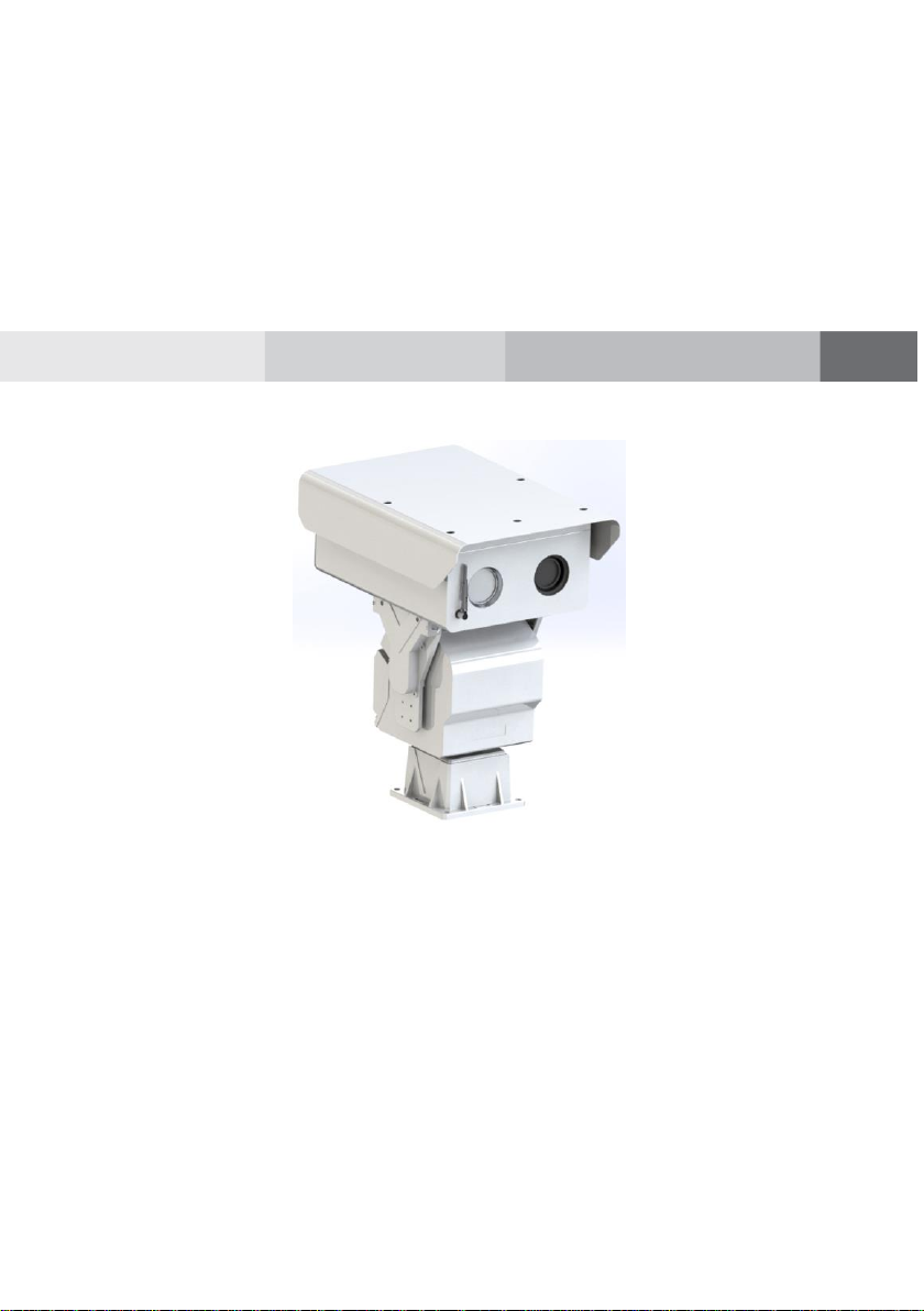
Bi-Spectral PTZ Network Camera, the whole machine shell and the base are all
made of high strength aluminum alloy material with comprehensive function and
high stability. Can adapt to a variety of bad environment, heavy load can reach
more than 50kg and run smoothly. This series has 360°continuous rotation,
automatic scanning, automatic cruise and other functions, suitable for large areas of

Overview
Bi-Spectral PTZ Network Camera
User Manual
8 Issue V1.0 (2019-04-08)
monitoring, can be widely used in airports, stations, urban roads, traffic survey and
monitoring, forest fire prevention, the high and heavy equipment rotary control and
other important area.
1.2.1 Function
To support a variety of scanning methods, such as cruise scan, pattern scanning, etc.
It supports the function of power off memory and automatically returns to the
monitoring scene before power off.
Support network signal and analog signal double output, cloud platform control
classification operation.
The double helix structure of worm gear and worm drive, the electronic image
stabilization, and mechanical locking design, power self-locking function.
Horizontal continuous rotation 360°,vertically +40° ~- 75° rotating, horizontal
velocity is 0.01°~60 °/S, vertical speed of 0.01° ~ 30°/S
Support proportion variable times function, rotation speed adjusted automatically
according to the lens change multiple times.
Support watch features preset point/figure/cruise can stay idle scan specified
Automatic call after time (including the idle state entered after power).
1.2.2 Product Features
Outdoor intelligent variable speed PTZ, the fuselage selection of high strength
aluminum alloy material, exterior design can resist strong winds, smooth operation,
high precision.
Products using high-precision stepper motor and precision worm gear drive
combination, power can be self-locking.
Support a variety of lens preset function, zoom adaptive function, the rotation
speed can be automatically adjusted according to the lens zoom factor.
Powerful, with preset, cruise, line sweep, keep watch and other functions.
Visual pitch angle range, monitoring a wide range of horizontal speed up to 6°/ s.
Equipment has its own automatic heating system, low temperature automatically
start heating function, to ensure that products can be applied to cold areas.
Network transmission signal can reach 100Mbps.
Device supports RS485 / RS422 communication interface, you can remotely
upgrade the device program, easy to maintain.
Power failure memory function, accidental power after re-power, the memory of
the last running state, can be restored to power before running state.
Bi-Spectral PTZ Network Camera
User Manual
Overview
Issue V1.0 (2019-04-08) 9
1.3 Description of PTZ cable
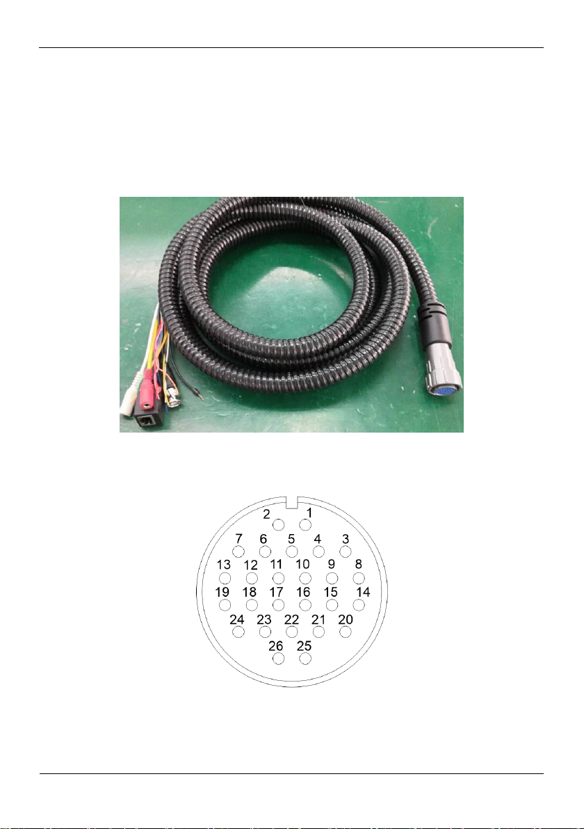
1.3.1 Aviation Power Supply and Network Cable of Twenty-six
Cores
Aviation power supply and network cable of twenty-six cores is shown as Figure 1-1 &
Figure 1-2, and the description is shown in Table 1-1.
Figure 1-1 Aviation power supply and network cable of twenty-six cores
Figure 1-2 Definition of twenty-six cores

Overview
Bi-Spectral PTZ Network Camera
User Manual
10 Issue V1.0 (2019-04-08)
Table 1-1 Description of twenty-six cores
SN
Name
Description
1
DC36V-
Black (Thick)
2
DC36V+
Red (Thick)
3
DC36V-
Black (Thick)
4
DC36V-
Black (Thick)
5
Alarm_OUT1
Red (Thin)
6
DC36V+
Red (Thick)
7
DC36V+
Red (Thick)
8
Audio_IN(G)
Audio masking
9
Audio_IN
Audio Core
10
Alarm_OUT1
Black (Thin)
11
Alarm_OUT3
Blue
12
Alarm_OUT3
Pink
13
Alarm_OUT4
White
14
Audio_OUT(G)
Audio masking
15
Audio_OUT
Audio Core
16
Video
Video Core
17
Video (G)
Video masking
18
Alarm_OUT2
White and Orange
19
Alarm_OUT4
Green
20
RS485A
Orange (Thick)
21
RS485B
Yellow (Thick)
22
ETHTX+
White and Orange
23
ETHTX-
Orange
24
Alarm_OUT2
White and Yellow
25
ETHRX+
White and Green
26
ETHRX-
Green
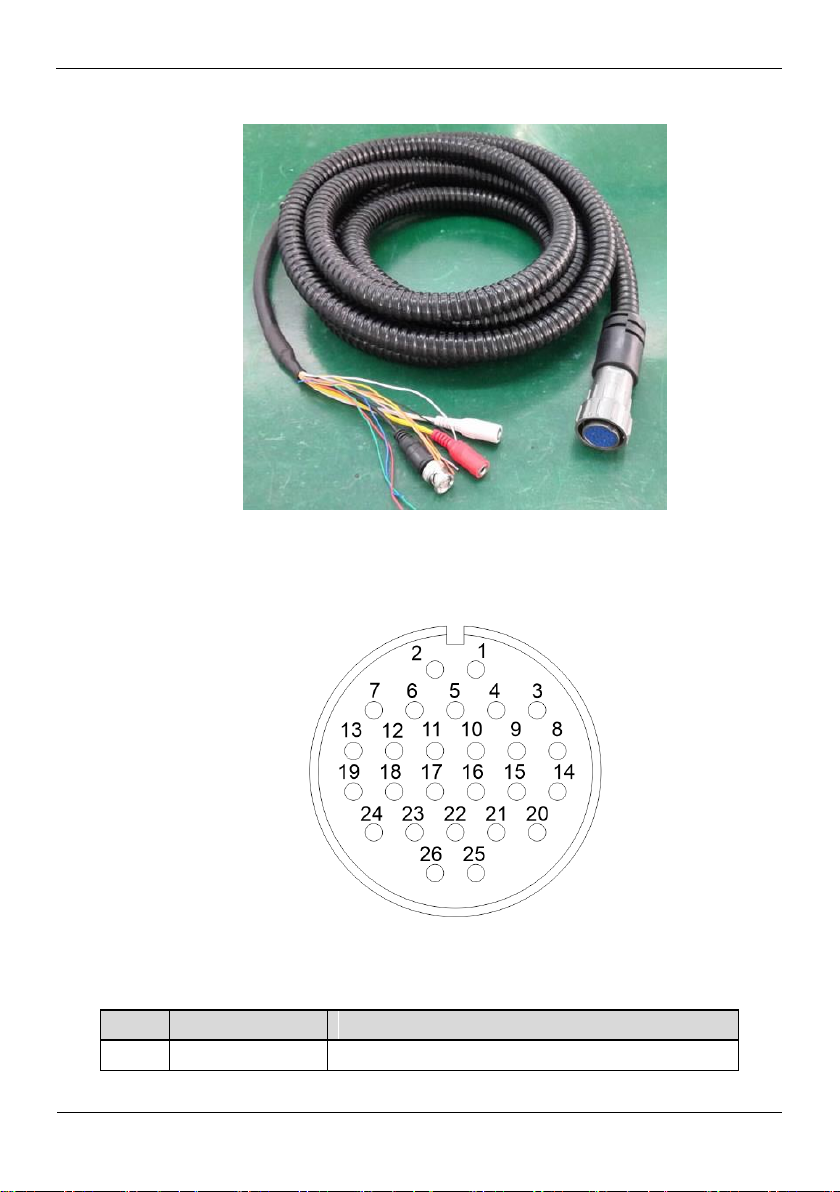
1.3.2 Aviation Alarm Cable of Twenty-Six Cores
Aviation alarm cable of twenty-six cores is shown as Figure 1-3& Figure 1-4, and the
description is shown in Table 1-2.
Bi-Spectral PTZ Network Camera
User Manual
Overview
Issue V1.0 (2019-04-08) 11
Figure 1-3 Aviation power supply cable of twenty-six cores
SN
Name
Description
1
Reserved core
Blank
Figure 1-4 Definition of twenty-six cores
Table 1-2 Description of twelve cores

Overview
Bi-Spectral PTZ Network Camera
User Manual
12 Issue V1.0 (2019-04-08)
SN
Name
Description
2
Reserved core
Blank
3
Reserved core
Blank
4
Reserved core
Blank
5
Reserved core
Ground
6
Reserved core
Blank
7
Reserved core
Blank
8
Reserved core
Ground
9
Reserved core
Ground
10
Reserved core
Blank
11
Alarm_IN1
White
12
Alarm_IN2
White and Orange
13
Alarm_IN3
Blue
14
Audio_IN(G)
Audio masking
15
Audio_IN
Audio Core
16
Video
Video Core
17
Video(G)
Video masking
18
Audio_OUT
Audio Core
19
Audio_OUT(G)
Audio masking
20
Alarm_IN4
Pink
21
Alarm_IN5
Red (Thin)
22
Alarm_IN6
White and Yellow
23
Alarm_IN7
Blank
24
Alarm_IN8
Yellow (Thick)
25
Alarm_IN9
Orange (Thick)
26
Alarm_G
Black (Thick)
----End

Bi-Spectral PTZ Network Camera
User Manual
Device Dimensions
Issue V1.0 (2019-04-08) 13
2 Device Dimensions
Figure 2-1 shows the dimensions of the Bi-Spectral PTZ Network Camera.
Figure 2-1 Dimensions (unit: mm)
Device Installation
Bi-Spectral PTZ Network Camera
User Manual
14 Issue V1.0 (2019-04-08)
3.1 Installation Method
Name
Quantity
Remarks
13mm wrench
1
For mounting fixtures and mounting
brackets
14mm sleeve
1
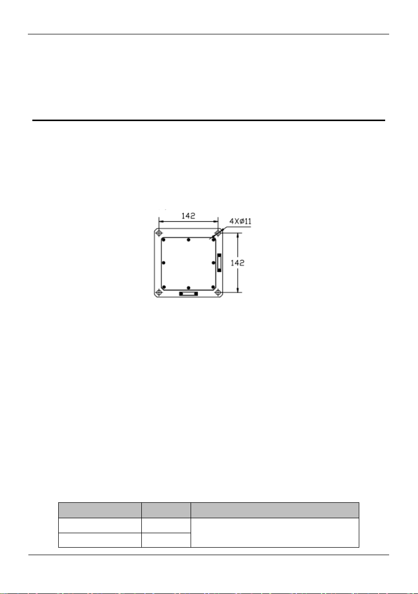
Bi-Spectral PTZ Network Camera can be installed on camera base.
Figure 3-1 shows the base dimensions of PTZ camera.
Figure 3-1 Base dimensions of PTZ camera (unit: mm)
3 Device Installation
3.2 Device Installation
3.2.1 Installation of Basic Requirements
Installation site and environment to meet the technical parameters mentioned in the
requirements, the installation staff should have been fully read and read the contents of
this manual, with the appropriate system installation qualification and maintenance
work qualification certificate.
3.2.2 Basic Installation Tool
Commonly used engineering wiring and equipment installation tools, please install the
equipment before the preparation is complete.
Table 3-1 shows the installation tools list.
Table 3-1 Installation tools

Bi-Spectral PTZ Network Camera
User Manual
Device Installation
Issue V1.0 (2019-04-08) 15
COLOR
Function define
Remark
BNC
Video
Optional
Red
DC36V+
Black
DC36V-
RJ45
Network cable
Orange
RS422 TX+
Yellow
RS422 TX-
Red
RS422 RX+
Blue
RS422 RX-
Yellow & Green
GND
Cross
screwdriver(big)
1
For common construction
Cross
screwdriver(small)
1
Used to disassemble the DIP cover to
adjust the device communication
parameters
Inside the hex
wrench
1 set
Used for disassembly of pan / tilt pallet and
shield connection
Word screwdriver
(small)
1
to secure the wiring harness connection
terminals
Wire strippers
1
Stripping
3.2.3 Installation Space and Installation Strength
Under normal circumstances, this device needs to be equipped with a protective cover
or other overhead items, please confirm the installation location can accommodate this
product and the equipment and installation of the structure of the space. To confirm the
installation of the wall, the carrying capacity of the bracket can reach 4 times the safety
of the entire equipment weight.
3.2.4 Definition of Installation Wiring Harness
The bottom line includes power line, network cable, RS422, geodetic line, video line,
and according to the demand, there are various types of outgoing line. The details need
to be controlled according to the line signature of each device.
Table 3-2 shows Definition of installation wiring harness.
Table 3-2 Definition of installation wiring harness
In order to prevent lightning strikes, the grounding wire (yellow-green wire) in the cable
outlet base must be grounded reliably and the grounding resistance should be <4Ω.

Device Installation
Bi-Spectral PTZ Network Camera
User Manual
16 Issue V1.0 (2019-04-08)
----End
Bi-Spectral PTZ Network Camera
User Manual
Quick Configuration
17 Issue V1.0 (2019-04-08)
4 Quick Configuration
4.1 Thermal Web
4.1.1 Login and Logout
You must use Internet Explorer 8 or a later version to access the web management
system; otherwise, some functions may be unavailable.
Login system
Step 1 Open the Internet Explorer, enter the IP address of IP camera (default value:
192.168.0.121) in the address box, and press Enter.
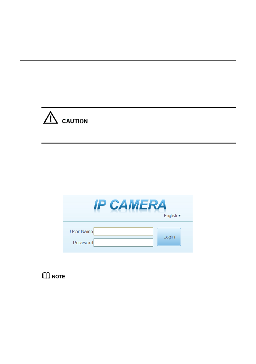
The login page is displayed, as shown in Figure 4-1.
Figure 4-1 Login page
Step 2 Input the User name and password.
The default user name is admin. The default password is admin. Change the password
when you log in the system for first time to ensure system security.
You can change the system display language on the login page.
Step 3 Click Login.
The main page is displayed.
----End
Quick Configuration
Bi-Spectral PTZ Network Camera
User Manual
18 Issue V1.0 (2019-04-08)
logout
1
2
3
4
5
6
7 8 9
101112
13
14
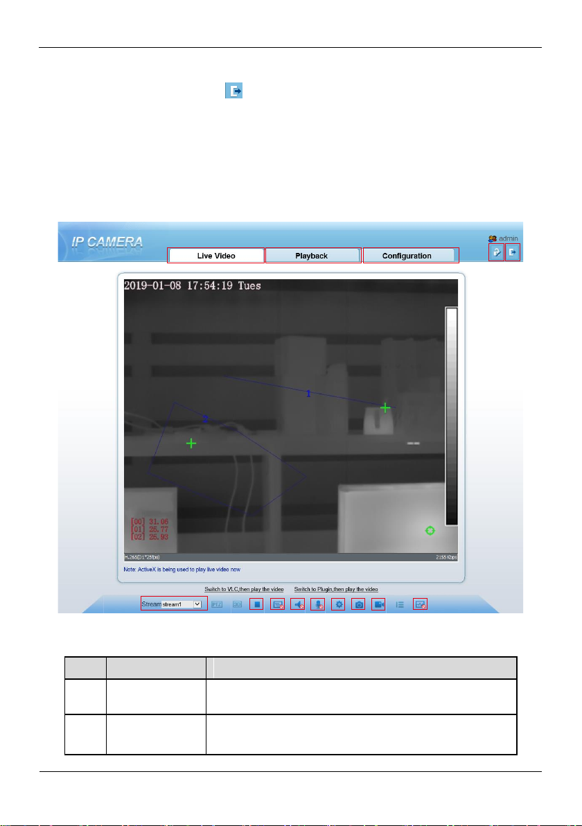
No.
Element
Description
1
Real-time video
area
Real-time videos are played in this area. You can also set
sensor parameters.
2
Playback
You can query the playback videos in this area.
NOTE
To logout of system, click in the upper right corner of the main page, the login page
is display after you log out of the system.
4.1.2 Main Page Layout
On the main page, you can view real-time video, set parameter, Video parameter, Video
control, PTZ control, PTZ Configure and log out of the system. Figure 4-2 is shown the
main page layout. Table 4-1 lists the elements on the main page layout.
Figure 4-2 Main page layout
Table 4-1 Elements on the main page
Bi-Spectral PTZ Network Camera
User Manual
Quick Configuration
19 Issue V1.0 (2019-04-08)
No.
Element
Description
Only when the SD card or NAS have videos that user can query
the playback videos.
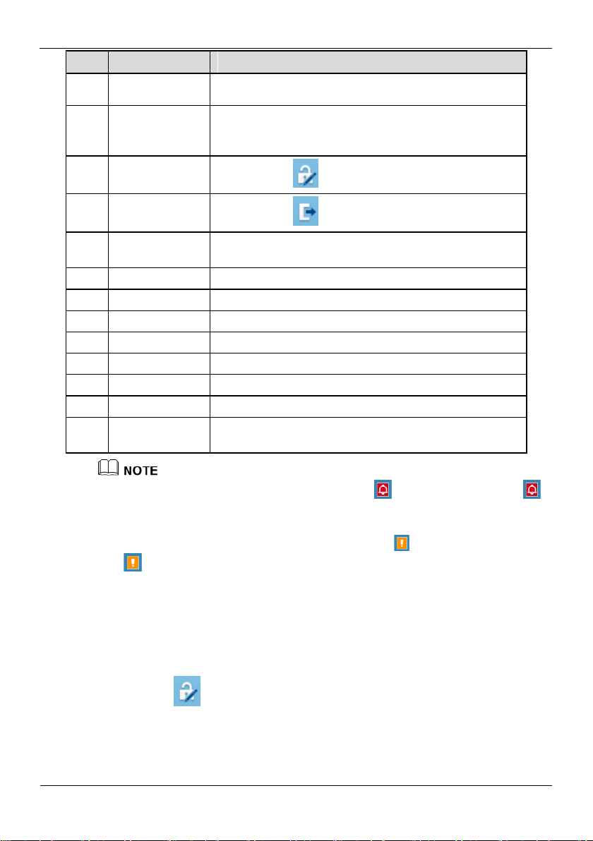
3
Device
configuration
You can choose a menu to set device parameters,
including the device information, audio and video streams,
alarm setting, and privacy mask function.
4
Change
password
You can click to change the password.
5
Sign Out
You can click to return to the login page.
6
Stream
Three are three streams. Choose one type from drop-down
list.
7
Pause/Start
Close live video or play live video.
8
Live/Smooth
Switch image quality.
9
Audio
Open or close audio.
10
Interphone
Open or close interphone.
11
Sensor setting
Click the icon, it will access to sensor setting.
12
Snapshot
Click the icon, it will snapshot.
13
Local record
Click the icon, it will record video and save.
14
Intelligent
analysis
Open or close intelligent analysis.
1. When the device generates an alarm, the alarm icon is displayed. You can click
to view the alarm information. When the device accepts an alarm signal, the alarm icon will
display within 10s in the web management system.
2. When the device encounters an exception, the fault icon is displayed. You can click
to view the fault information.
----End
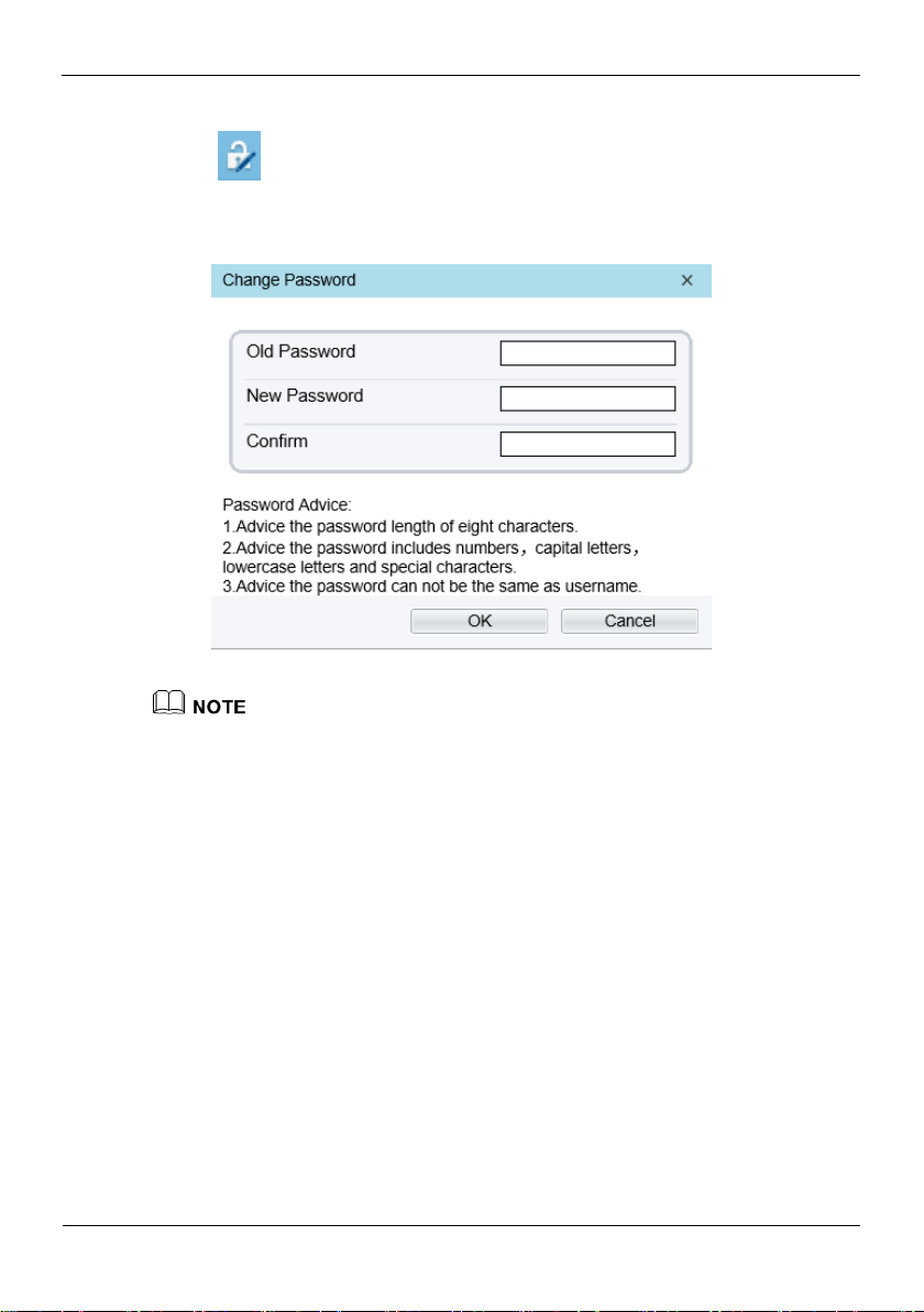
4.1.3 Change the Password
Description
You can click to change the password for logging in to the system.
Quick Configuration
Bi-Spectral PTZ Network Camera
User Manual
20 Issue V1.0 (2019-04-08)
Procedure
Step 1 Click in the upper right corner of the main page.
The Change Password dialog box is displayed, as shown in Figure 4-3.
Figure 4-3 Modify Password dialog box
The change password page will be displayed if you don’t change the default password when
you login the system for the first time.
Step 2 Enter the old password, new password, and confirmation password.
Step 3 Click OK.
If the message "Change own password success" is displayed, the password is
successfully changed. If the password fails to be changed, the cause is displayed. (For
example, the new password length couldn’t be less than eight.)
Step 4 Click OK.
The login page is displayed.
----End
4.1.4 Browse Video
User can browse the real-time video in the web management system.
Preparation
To ensure the real-time video can be play properly, you must perform the following
operation when you log in to the web for the first time:

Bi-Spectral PTZ Network Camera
User Manual
Quick Configuration
21 Issue V1.0 (2019-04-08)
Step 1 Open the Internet Explorer. Choose Tools > Internet options > Security > Trusted
sites > Sites.
In the display dialog box, click Add, as shown in Figure 4-4.
Figure 4-4 Adding the a trusted site
Step 2 In the Internet Explorer, choose Tool > Internet Options > Security > Customer
level, and set Download unsigned ActiveX control and initialize and script ActiveX
controls not marked as safe for scripting under ActiveX controls and plug-ins to Enable,
as shown in Figure 4-5.
Figure 4-5 Configuring ActiveX control and plug-ins
Quick Configuration
Bi-Spectral PTZ Network Camera
User Manual
22 Issue V1.0 (2019-04-08)
Step 3 Download and install the player control as prompted.
The login page is display when the control is loaded.
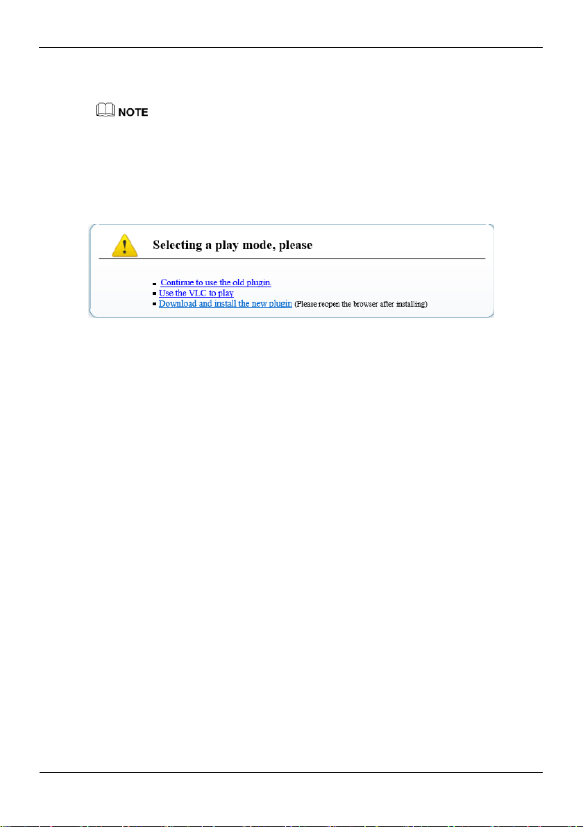
4.1.5 Install Plugins
You will be prompted with a message “Download and install the new plugin” as shown
in Figure 4-6 when you log in to the web management system for the first time.
Figure 4-6 Download the plugin page
Procedure
Step 1 Click the message, download and install the plugin follow the prompts.
Step 2 Reopen the browser after installation.
----End
4.1.6 Set Local Network Parameters
Description
Local network parameters include:
IP protocol
IP address
Subnet mask
Default gateway
Dynamic Host Configuration Protocol (DHCP)
Preferred Domain Name System (DNS) server
Alternate DNS server
MTU
Procedure
Step 1 Choose Configuration > Device >Local Network.
The Local Network page is displayed, as shown in Figure 4-7.

Bi-Spectral PTZ Network Camera
User Manual
Quick Configuration
23 Issue V1.0 (2019-04-08)
Figure 4-7 Local Network page
Parameter
Description
Setting
IP Protocol
IPv4 is the IP protocol that uses
an address length of 32 bits.
[Setting method]
Select a value from the
drop-down list box.
[Default value]
IPv4
DHCP
The device automatically
obtains the IP address from the
DHCP server.
[Setting method]
Click the option button.
NOTE
To query the current IP
address of the device, you
must query it on the
platform based on the
device name.
DHCP IP
IP address that the DHCP server
assigned to the device.
N/A
IP Address
Device IP address that can be
set as required.
[Setting method]
Enter a value manually.
[Default value]
192.168.0.120
Step 2 Set the parameters according to Table 4-2.
Table 4-2 Local network parameters

Quick Configuration
Bi-Spectral PTZ Network Camera
User Manual
24 Issue V1.0 (2019-04-08)
Parameter
Description
Setting
Subnet Mask
Subnet mask of the network
adapter.
[Setting method]
Enter a value manually.
[Default value]
255.255.255.0
Default Gateway
This parameter must be set if
the client accesses the device
through a gateway.
[Setting method]
Enter a value manually.
[Default value]
192.168.0.1
Preferred DNS
Server
IP address of a DNS server.
[Setting method]
Enter a value manually.
[Default value]
192.168.0.1
Alternate DNS
Server
IP address of a domain server.
If the preferred DNS server is
faulty, the device uses the
alternate DNS server to resolve
domain names.
[Setting method]
Enter a value manually.
[Default value]
192.168.0.2
MTU
Set the maximum value of
network transmission data
packets.
[Setting method]
Enter a value manually.
NOTE
The MTU value is range
from 800 to 1500, the
default value is 1500,
Please do not change it
arbitrarily.
Step 3 Click OK.
If the message "Apply success" is displayed, click OK. The system saves the
settings. The message "Set network pram’s success, Please login system again" is
displayed. Use the new IP address to log in to the web management system.
If the message "Invalid IP Address", "Invalid Subnet Mask", "Invalid default
gateway", "Invalid primary DNS", or "Invalid space DNS" is displayed, set the
parameters correctly.
If you set only the Subnet Mask, Default Gateway, Preferred DNS Server, and
Alternate DNS Server parameters, you do not need to log in to the system again.
You can click Reset to set the parameters again if required.
----End

Bi-Spectral PTZ Network Camera
User Manual
Quick Configuration
25 Issue V1.0 (2019-04-08)
4.1.7 Thermal Settings
Parameter
Description
Setting
Temperature Unit
Celsius and Fahrenheit
temperature units are available.
[Setting method]
Select a value from the
drop-down list box.
[Default value]
Celsius
Ambient
Temperature
The ambient temperature of
camera. It is set when ambient
is outside.
[Setting method]
Enter a value manually.
4.1.7.1 Temperature Parameters
Temperature parameters include: temperature unit, ambient type, ambient temperature,
cavity temperature, correctional coefficient and area temperature display mode.
Operation Procedure
Step 1 Choose Configuration >Thermal >Temperature Parameters.
The Temperature Parameters page is displayed, as shown in Figure 4-8.
Figure 4-8 Temperature Parameters interface
Step 2 Set the parameters according to Table 4-3.
Table 4-3 Temperature parameters
 Loading...