

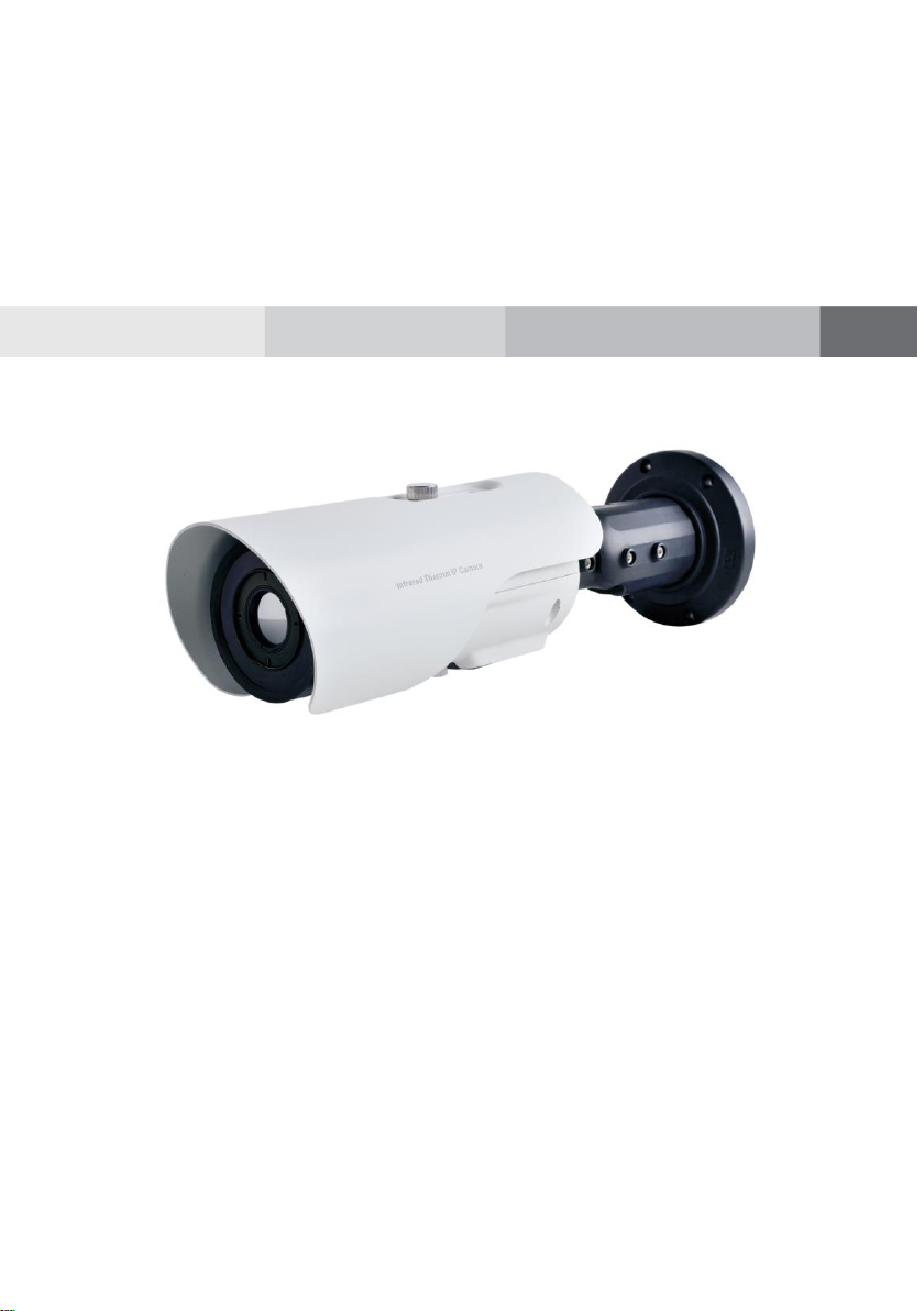
Thermal Imaging Integrated Network Camera
User Manual
Issue
V1.0
Date
2019-08-06

Thermal Imaging Integrated Network Camera
User Manual
Precautions
Issue V1.0 (2019-08-06) i
Precautions
Symbol
Description
It alerts you to fatal dangers which, if not avoided, may
cause deaths or severe injuries.
It alerts you to moderate dangers which, if not avoided,
may cause minor or moderate injuries.
It alerts you to risks. Neglect of these risks may cause
device damage, data loss, device performance
deterioration, or unpredictable results.
It provides a tip that may help you resolve problems or
save time.
It provides additional information.
Fully understand this document before using this device, and strictly observe rules in
this document when using this device. If you install this device in public places,
provide the tip "You have entered the area of electronic surveillance" in an eyecatching place. Failure to correctly use electrical products may cause fire and severe
injuries. To prevent accidents, carefully read the following context:
Symbols
This document may contain the following symbols whose meanings are described
accordingly.
Precautions
To prevent electric shocks or other dangers, keep power plugs dry and clean.
Strictly observe installation requirements when installing the device. The
manufacturer shall not be held responsible for device damage caused by users' nonconformance to these requirements.

Precautions
Thermal Imaging Integrated Network Camera
User Manual
ii Issue V1.0 (2019-08-06)
Strictly conform to local electrical safety standards and use power adapters which
are marked with the LPS standard when installing and using this device. Otherwise,
this device may be damaged.
Use accessories delivered with this device. The voltage must meet input voltage
requirements for this device.
If this device is installed in places with unsteady voltage, ground the device to
discharge high energy such as electrical surges in order to prevent the power supply
from burning out.
When this device is in use, ensure that no water or any liquid flows into the device.
If water or liquid unexpectedly flows into the device, immediately power off the
device and disconnect all cables (such as power cables and network cables) from
this device.
Do not place the thermal imaging camera and unpackaged products at a radiation
source with a high intensity regardless of whether the device is in the normal
power-on state, for example, the sun, laser, and electric arc welder, and place the
thermal imaging camera and unpackaged products against objects with a high heat
source, for example, the sun. Otherwise, the accuracy of the thermal imaging
camera will be affected. In addition, the detector in the thermal imaging camera
may be permanently damaged.
If this device is installed in places where thunder and lightning frequently occur,
ground the device nearby to discharge high energy such as thunder strikes in order
to prevent device damage.
Unless otherwise specified in the user manual, do not use the thermal imaging
camera in an environment with the temperature lower than -10C (+14F) or higher
than 50C (+122F). Otherwise, the images displayed by the thermal imaging
camera are abnormal and the device may be damaged if working beyond the
temperature range for a long period.
During the outdoor installation, prevent the morning or evening sunlight incidence
to the lens of the thermal imaging camera. The sun shade must be installed and
adjusted according to the angle of the sunlight illumination.
Avoid heavy loads, intensive shakes, and soaking to prevent damages during
transportation and storage. The warranty does not cover any device damage that is
caused during secondary packaging and transportation after the original packaging
is taken apart.
This device is a static sensitivity device. Improper static may damage the thermal
imaging camera. ESD protection measures and reliable grounding must be well
prepared for device installation and uninstallation.
Protect this device from fall-down and intensive strikes, keep the device away from
magnetic field interference, and do not install the device in places with shaking
surfaces or under shocks.

Thermal Imaging Integrated Network Camera
User Manual
Precautions
Issue V1.0 (2019-08-06) iii
Use a soft and dry cloth to clean the device body. In case that the dirt is hard to
remove, use a dry cloth dipped in a small amount of mild detergent and gently wipe
the device, and then dry it again. Pay special attention to the front window of the
thermal imaging camera because this is precision optics. If the front window has
water spots, use a clean and soft cloth moistened with water then wipe it. If the
front window needs further cleaning, use a soft cloth dampened with isopropyl
alcohol or detergent. Improper cleaning can cause damage to the device.
The lens window of the thermal imaging camera is designed to be applicable to an
outdoor environment. The window is coated with durable coating material, but may
require frequent cleaning. When you found lens image degradation or excessive
accumulation of pollutants, you should clear up the window in a timely manner.
Exercise caution when you use this device in severe sandstorm (such as deserts) or
corrosive environments (such as offshore). Improper use may cause surface coating
off.
Do not jam the ventilation opening. Follow the installation instructions provided in
this document when installing the device.
Keep the device away from heat sources such as radiators, electric heaters, or other
heat equipment.
Keep the device away from moist, dusty, extremely hot or cold places, or places
with strong electric radiation.
If the device is installed outdoors, take insect- and moisture-proof measures to
avoid circuit board corrosion that can affect monitoring.
Remove the power plug if the device is idle for a long time.
Before unpacking, check whether the fragile sticker is damaged. If the fragile
sticker is damaged, contact customer services or sales personnel. The manufacturer
shall not be held responsible for any artificial damage of the fragile sticker.
Special Announcement
All complete products sold by the manufacturer are delivered along with nameplates,
operation instructions, and accessories after strict inspection. The manufacturer shall
not be held responsible for counterfeit products.
This manual may contain misprints, technology information that is not accurate enough,
or product function and operation description that is slightly inconsistent with the
actual product. The manufacturer will update this manual according to product function
enhancement or changes and regularly update the software and hardware described in
this manual. Update information will be added to new versions of this manual without
prior notice.
This manual is only for reference and does not ensure that the information is totally
consistent with the actual product. For consistency, see the actual product.

Contents
Thermal Imaging Integrated Network Camera
User Manual
iv Issue V1.0 (2019-08-06)
Contents
1 Product Overview .................................................................................................... 1
1.1 Thermal Imaging Principles and Advantages ................................................................. 1
1.2 Device Structure ............................................................................................................. 1
1.3 Cable Connection ........................................................................................................... 3
1.4 Functions and Features ................................................................................................... 4
2 Device Dimensions ................................................................................................. 5
3 Installation ................................................................................................................ 6
3.1 Preparations .................................................................................................................... 6
3.2 Installation Mode............................................................................................................ 7
3.3 Installation Procedure ..................................................................................................... 7
4 Quick Configuration ............................................................................................. 12
4.1 Login and Logout ......................................................................................................... 12
4.2 Main Page Layout ........................................................................................................ 13
4.3 Change the Password.................................................................................................... 15
4.4 Browse Video ............................................................................................................... 16
4.4.1 Install Plugins ................................................................................................... 18
4.5 Set Local Network Parameters ..................................................................................... 18
5 Thermal Setting ...................................................................................................... 21
5.1 Temperature Parameters ............................................................................................... 21
5.2 Temperature Area ......................................................................................................... 24
5.3 Shield Area ................................................................................................................... 27
5.4 Schedule Linkage ......................................................................................................... 28
5.5 Bad Point Check ........................................................................................................... 30
5.6 Version Information ...................................................................................................... 31
6 Parameter Setting ................................................................................................... 32
6.1 Sensor Configuration Interface ..................................................................................... 32
6.2 Time Segment ............................................................................................................... 32
6.3 Images .......................................................................................................................... 33
6.4 Scene ............................................................................................................................ 34
6.5 Pseudocolor .................................................................................................................. 35

Thermal Imaging Integrated Network Camera
User Manual
Contents
Issue V1.0 (2019-08-06) v
6.6 FFC Control ................................................................................................................. 37
6.7 Noise Reduction ........................................................................................................... 38
6.8 Enhance Image ............................................................................................................. 39
7 Technical Specifications ....................................................................................... 41
A Troubleshooting.................................................................................................... 45
B Common Emission Rate ....................................................................................... 47


Thermal Imaging Integrated Network Camera
User Manual
Product Overview
Issue V1.0 (2019-08-06) 1
1 Product Overview
1.1 Thermal Imaging Principles and Advantages
For any object, as long as its temperature is above the absolute zero (-273.15°C),
although the object does not give out light, it can radiate infrared. The infrared is also
known as thermal radiation. A temperature change occurs when the infrared radiated by
objects at different temperatures is absorbed by the infrared thermal detector, and
thereby generating an electrical effect. An electrical signal is amplified and processed
to obtain a thermal image corresponding to the distribution of heat on the surface of the
object, that is, infrared thermal imaging.
Applicable to any light environment
Traditional cameras rely on the natural or ambient light for imaging. However, the
infrared thermal imaging camera can clearly image the object with the infrared heat
radiation of the object without relying on any light. The infrared thermal camera is
applicable to any light environment and is free from glare impact. It can clearly
detect and find the target as well as identify the camouflaged and hidden target in
both day and night. Therefore, it achieves real 24-hour surveillance.
Monitoring the temperature field of the target heat distribution
The infrared thermal camera can display the temperature field of the object and
change the surface temperature distribution of the object that cannot be directly
seen by human eyes to the thermal image representing the surface temperature
distribution of the object. By monitoring the temperature field, you can
immediately identify the temperature abnormality, thereby preventing potential
risks caused by the temperature, such as fire.
Providing the cloud penetration capability
Atmosphere, dust, and clouds can absorb visible light and near-infrared, but are
clear to the thermal infrared for 3 to 5 microns (medium wave infrared region) and
8 to 14 micron (long wave infrared). Therefore, it is difficult for the conventional
cameras to capture clear images under dense clouds, while the thermal imaging
camera is able to effectively penetrate the atmosphere and clouds to capture clear
images.
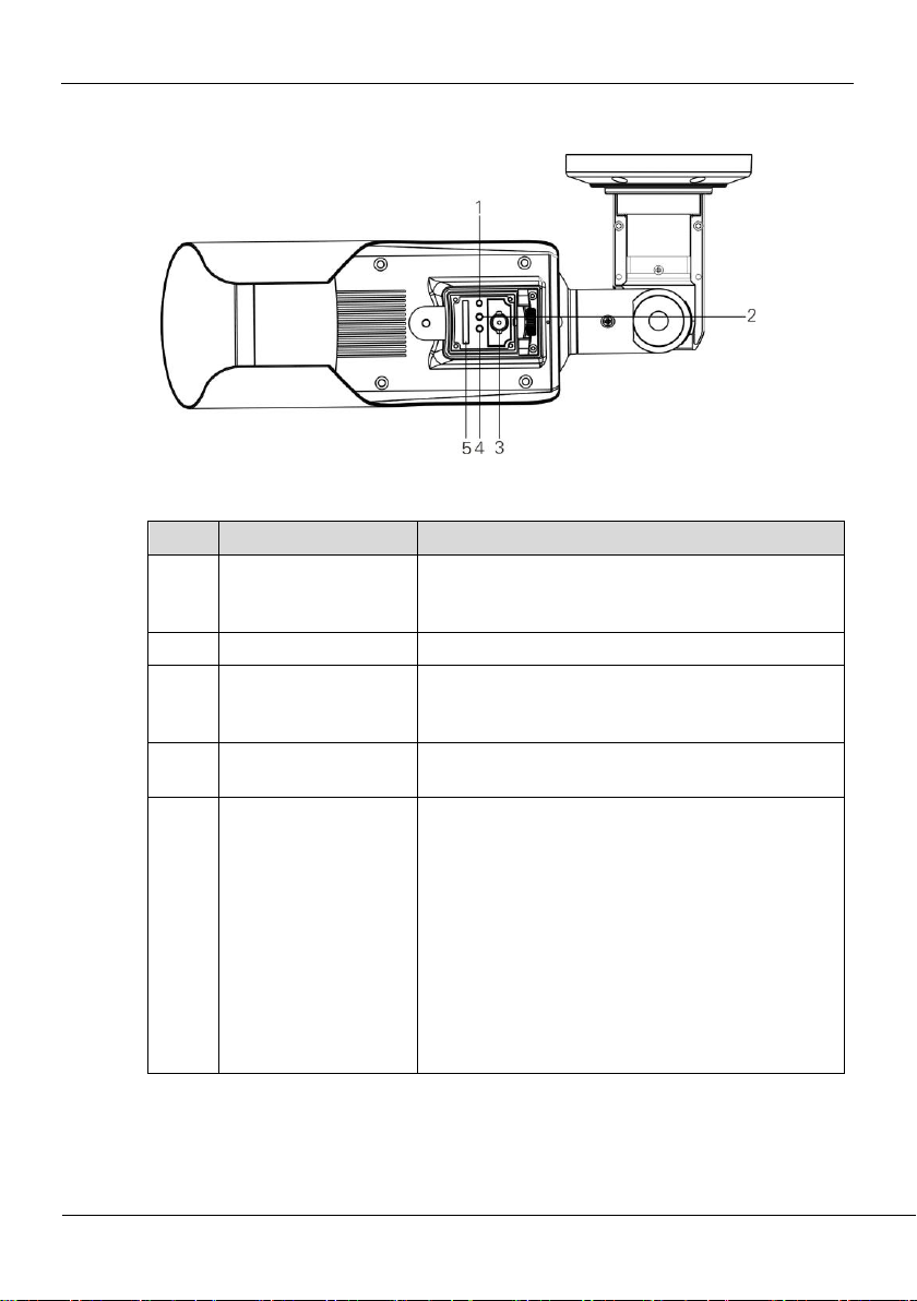
1.2 Device Structure
Figure 1-1 shows the rear panel of the thermal imaging integrated network camera. For
details about the interfaces, see Table 1-1.
Product Overview
Thermal Imaging Integrated Network Camera
User Manual
2 Issue V1.0 (2019-08-06)
Figure 1-1 Appearance and interfaces of the thermal imaging integrated network
No.
Physical Interface
Connection
1
Reset button
(RESET)
The configuration resumes to the factory settings
after you press the reset button for 3s. The default
value of IP is 192.168.0.121.
2
Network indicator
Network connection indicator
3
Video output
(VOUT)
It outputs the analog video signals and can be
connected to the TV monitor to view analog
videos.
4
Power indicator
The indicator lights on when the power is plugged
in.
5
SD card slot
It places the SD card.
Note:
When you install the SD card, ensure that the
SD card is not in the write-protection state and
then insert the SD card in the SD card slot.
When you remove the SD card, ensure that the
SD card is not in the write-protection state.
Otherwise, the data may be lost or the SD card
may be damaged.
When hot plugging the SD card, stop recording
and then perform the corresponding operation.
camera
Table 1-1 Interfaces of camera
Thermal Imaging Integrated Network Camera
User Manual
Product Overview
Issue V1.0 (2019-08-06) 3
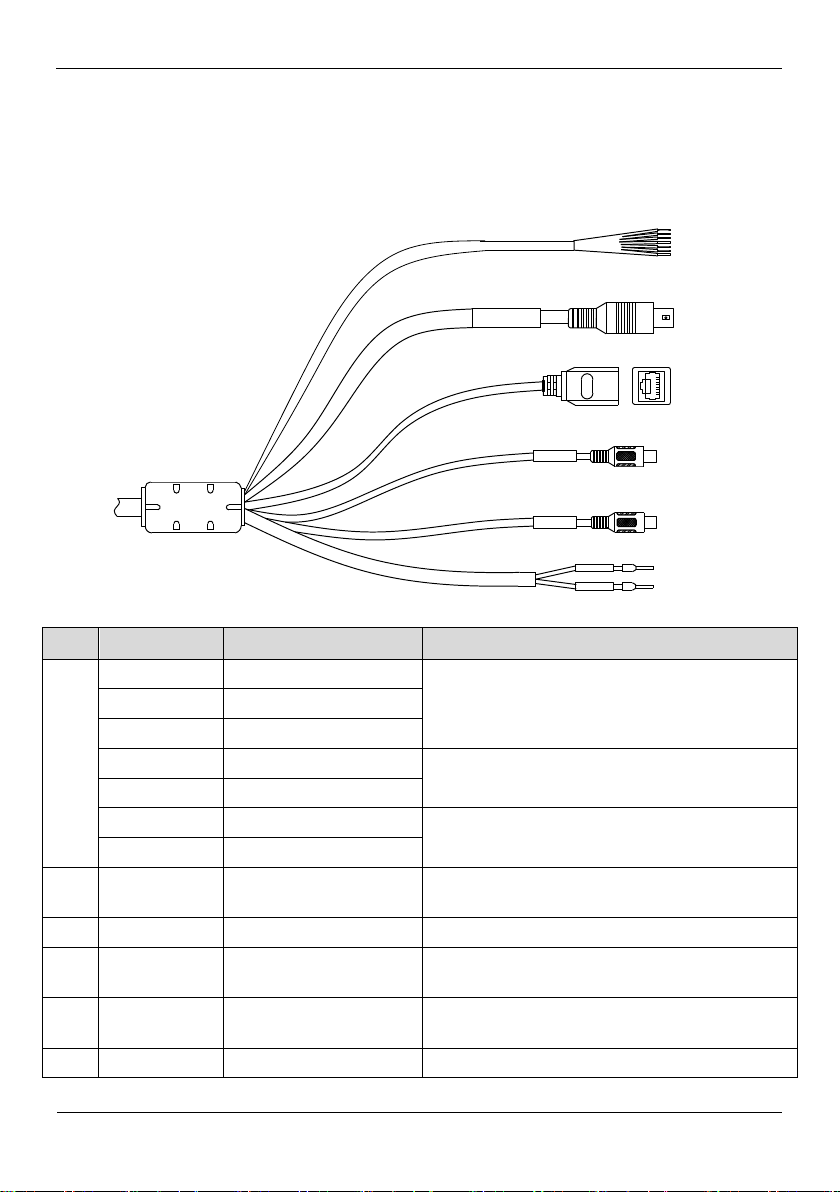
1.3 Cable Connection
Audio Input
A u di o O utpu t
4
3
2
6
5
1
ID
Color
Functions
Connection
1
Orange
ALARM OUT COM 1
Connects to the alarm output device.
Yellow
A LARM OUT 1
Grey
ALARM OUT COM
Purple
ALARM IN 1
Connects to the alarm input device.
Blue
ALARM IN 2
White / Black
A LARM OUT COM 1
Connects to the alarm output device.
White / Blue
ALARM OUT 2
2
--
DC12V (2 A) / AC 24
V
Power interface, connects to the 12 V DC power
supply.
3
--
Network interface
Connects to the standard Ethernet cable.
4
--
Audio Output
Connects to an external audio device such as a
speaker.
5
--
Audio Input (cable
input)
Receives an analog audio signal from devices
such as a sound pickup device.
6
Brown
RS485+
RS485 interface connects to the external pan &
Figure 1-2 the multi-connector combination cable of the thermal imaging integrated
network camera. For details about the multi-connector combination cable, see Table 1-
2.
Figure 1-2 Multi-connector combination cable
Table 1-2 Multi-connector combination cable

Product Overview
Thermal Imaging Integrated Network Camera
User Manual
4 Issue V1.0 (2019-08-06)
ID
Color
Functions
Connection
White
RS 485-
tilt.
1.4 Functions and Features
Using the uncooled infrared focal plane sensor
Detecting the infrared wavelength ranging from 8 um to 14 um
800*600 pixels
High thermal sensitivity, reaching 40mK
Support dedicated lens for 8/15/25/35/50 mm focal distance (optional)
Support 17 pseudo color modes such as black hot, white hot, rainbow, iron bow and
so on
Support the DVE image enhancement
Support noise reduction and mirroring
Support three coding algorithms, that is H.265, H.264 and MJPEG, it is high
compatibility
In the heat setting temperature measuring points in the image or temperature area,
temperature detection and display: point temperature measurement, regional
temperature measuring, full screen, temperature measurement.
Over temperature warning and over temperature alarm
Output three coded streams in real time, and satisfying local storage and network
transmission of the video
1-channel audio input and 1-channel audio output, supporting bidirectional voice
talkback
Support the local storage of the Micro SD card (the maximum capacity is 128 GB)
and effectively resolving the video loss problem caused by network failure
Support NAS storage and Micro SD card
Provide software and hardware watchdogs and automatic fault recovery
Linked heat dissipation structure of the metal enclosure
3-axis rotational adjustment structure facilitating installation and adjustment
DC12V/AC24V/POE
Thermal Imaging Integrated Network Camera
User Manual
Device Dimensions
Issue V1.0 (2019-08-06) 5
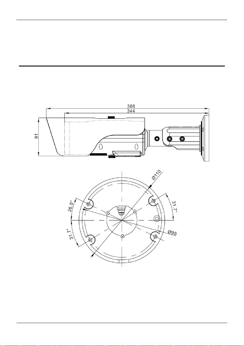
2 Device Dimensions
Figure 2-1 shows the dimensions of device.
Figure 2-1 Dimensions (unit: mm)
Installation
Thermal Imaging Integrated Network Camera
User Manual
6 Issue V1.0 (2019-08-06)
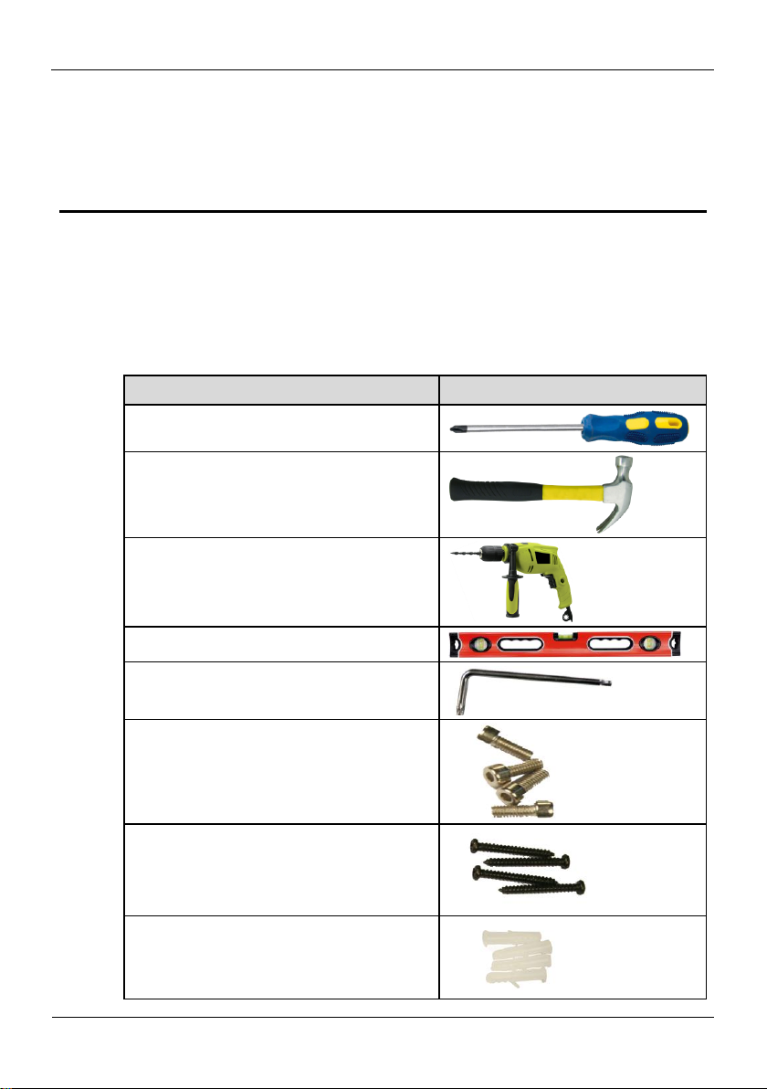
3.1 Preparations
Tools
Appearance
Phillips screwdriver (prepare by yourself)
Claw hammer (prepare by yourself)
Hammer drill (prepare by yourself)
Spirit level (prepare by yourself)
T15 ring spanner (delivered with the
camera)
Stainless hexagon socket head cap screw
(delivered with the camera)
Self-tapping screw (delivered with the
camera)
Inflatable colloidal particle (delivered with
the camera)
You may need the tools and accessories shown in Table 3-1 during the installation (you
need to prepare the tools by yourself, and the accessories are in the package of the
camera).
3 Installation
Table 3-1 Installation tools
Thermal Imaging Integrated Network Camera
User Manual
Installation
Issue V1.0 (2019-08-06) 7
3.2 Installation Mode
NOTE
NOTE
Location label
Wall
The thermal imaging integrated camera can be installed on the ceiling or the wall. You
can select the appropriate installation according to your requirements. If the camera
needs to be installed on the cement wall, you need to install the expansion screws (the
mounting holes of the screws must be consistent with that of the support), and then
install the support.
The wall where the support is mounted must be able to withstand at least three times of the
total weight of the support and the camera.
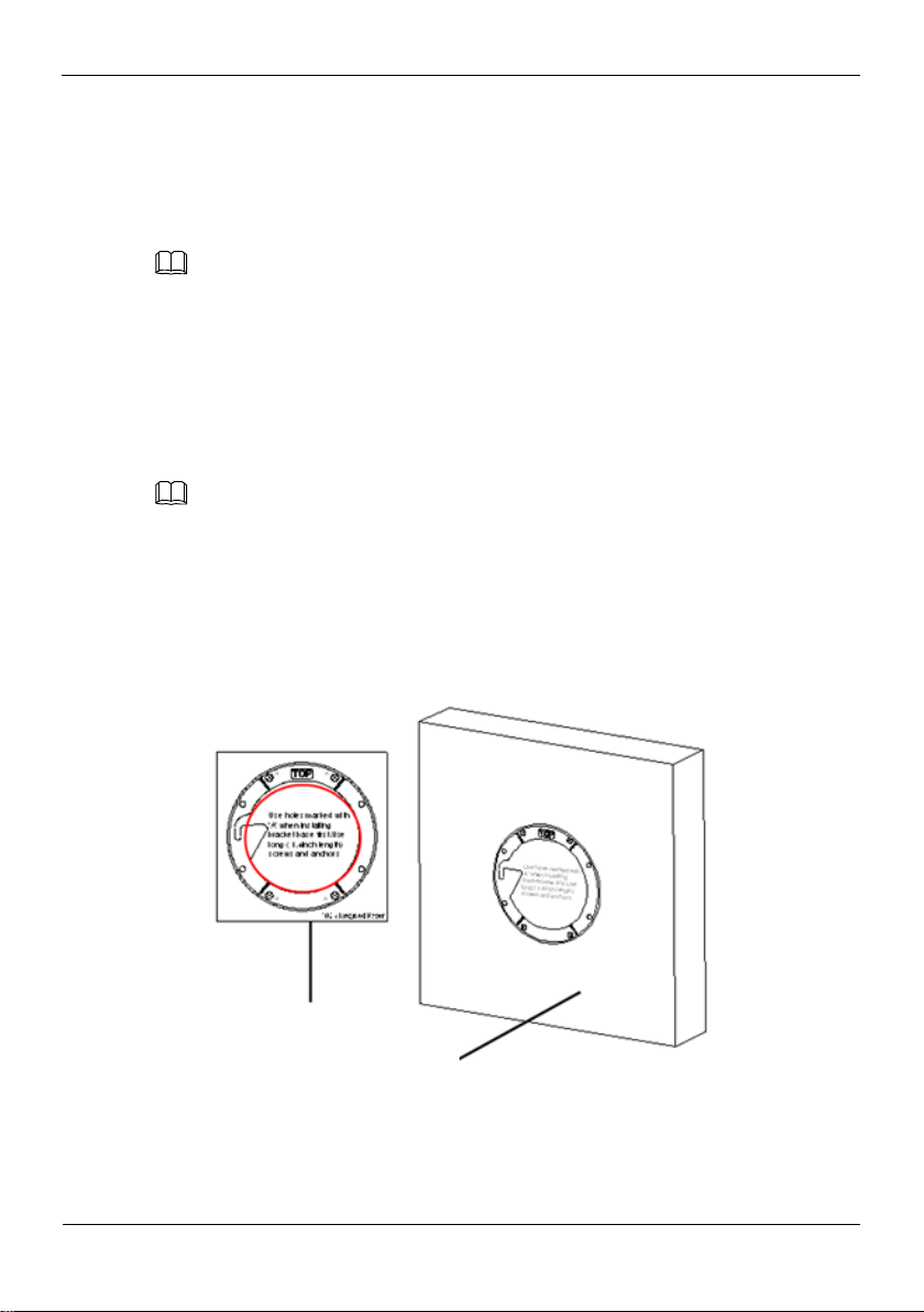
3.3 Installation Procedure
Step 1 Remove the installation location labels delivered with the camera. Stick the installation
location labels on the ceiling or the wall, as shown in Figure 3-1.
If the installation uses the back leading mode, pouch a leading-out hole on the ceiling or
the wall, as shown in the area highlighted in red in Figure 3-1. (This manual uses the
back leading mode as an example.)
If the installation uses the side leading mode, lead the multi-connector combination cable
from the side notch on the bottom of the camera.
Figure 3-1 Installation location label
Step 2 According to the location hole positions shown in the installation location label, punch
four location holes with diameter 5 mm on the ceiling or the wall.
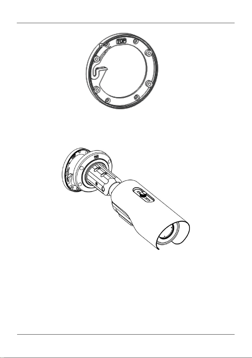
Step 3 Fix the installation base on the wall, as shown in Figure 3-2.
Installation
Thermal Imaging Integrated Network Camera
User Manual
8 Issue V1.0 (2019-08-06)
Figure 3-2 Fixing base
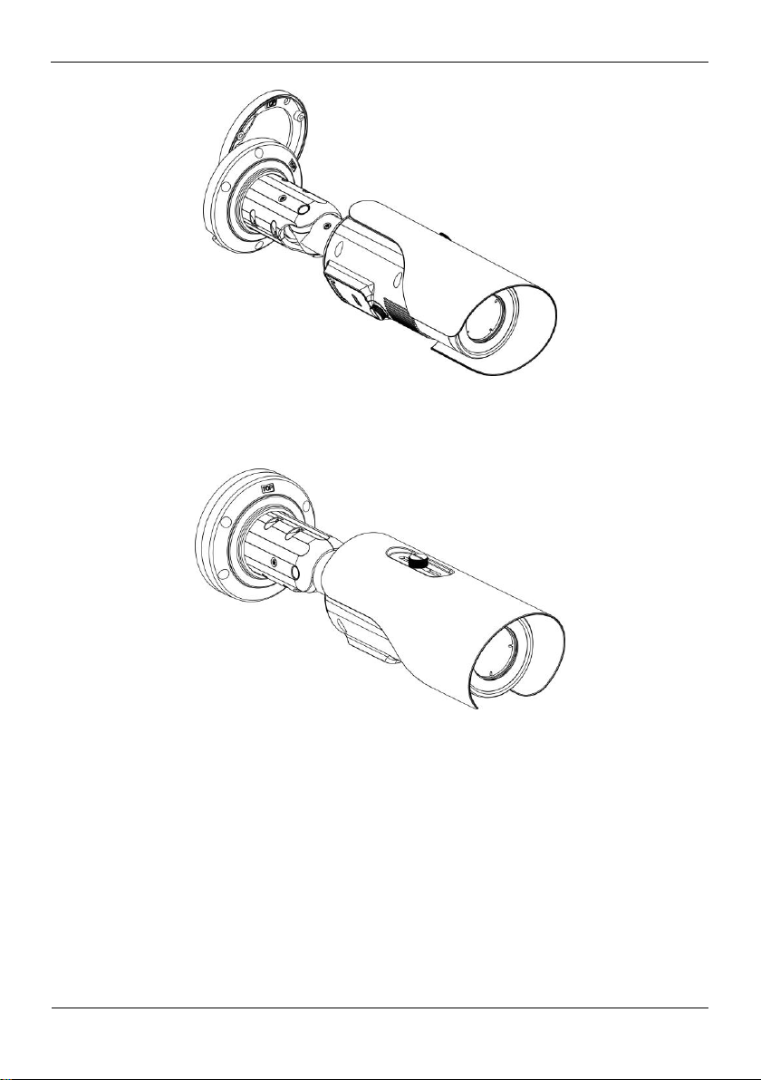
Step 4 Hang the integrated camera into the base along the guide slots and rotate it to a certain
angle to facilitate cable connection, as shown in Figure 3-3.
Figure 3-3 Hang the integrated camera into the base
Step 5 Connect and conceal the cables for the integrated camera. After the cable connection is
complete, rotate the integrated camera to align at the installation base, as shown in
Figure 3-4.
Thermal Imaging Integrated Network Camera
User Manual
Installation
Issue V1.0 (2019-08-06) 9
Figure 3-4 Align at the base
Step 6 Fix the integrated camera to the installation base, as shown in Figure 3-5.
Figure 3-5 Fix the integrated camera to the installation base
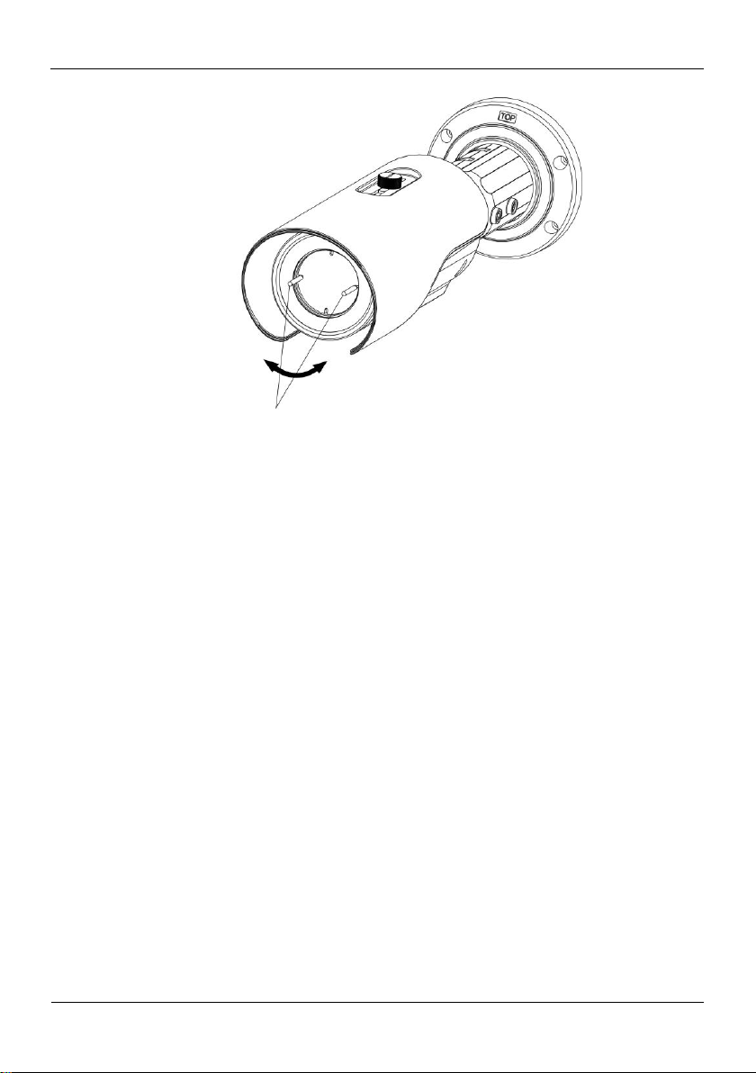
Step 7 Focus with focusing screw
Insert the focusing screw into the screw hole and focus along the direction of arrows as
shown in Figure 3-6.
Installation
Thermal Imaging Integrated Network Camera
User Manual
10 Issue V1.0 (2019-08-06)
Figure 3-6 Focus with focusing screw
Focusing screw
Step 8 Adjust the surveillance angle, as shown in Figure 3-7, and then fix the screws.

Thermal Imaging Integrated Network Camera
User Manual
Installation
Issue V1.0 (2019-08-06) 11
---End
Figure 3-7 Adjust the surveillance angle

Quick Configuration
Thermal Imaging Integrated Network Camera
User Manual
12 Issue V1.0 (2019-08-06)
4 Quick Configuration
4.1 Login and Logout
You must use Internet Explorer 8 or a later version to access the web management
system; otherwise, some functions may be unavailable.
Login system
Step 1 Open the Internet Explorer, enter the IP address of IP camera (default value:
192.168.0.121) in the address box, and press Enter.
The login page is displayed, as shown in Figure 4-1.
Figure 4-1 Login page
Step 2 Input the user name and password.
The default name and password are both admin. Modify the password when you login
the system for first time to ensure system security. After modifying password, you need
to wait at least three minutes then power off to make sure modifying successfully . Or
login the Web again to test the new password.
You can change the system display language on the login page.
Step 3 Click Login.
The main page is displayed.
----End

Thermal Imaging Integrated Network Camera
User Manual
Quick Configuration
Issue V1.0 (2019-08-06) 13
Logout
1
2
3
4
5
6
7 8 9
101112
13
14
No.
Element
Description
1
Real-time video
area
Real-time videos are played in this area. You can also set
sensor parameters.
2
Playback
You can query the playback videos in this area.
To logout of system, click in the upper right corner of the main page, the login
page is displayed after you logout of the system.
4.2 Main Page Layout
On the main page, you can view real-time video, playback and configuration. You can
set parameter, Video parameter, Video control, PTZ control, PTZ Configure and logout
of the system. Figure 4-2 is shown the main page layout. Table 4-1 lists the elements on
the main page layout.
Figure 4-2 Main page layout
Table 4-1 Elements on the main page

Quick Configuration
Thermal Imaging Integrated Network Camera
User Manual
14 Issue V1.0 (2019-08-06)
No.
Element
Description
Only when the SD card or NAS have videos that user can query
the playback videos.
3
Device
configuration
You can choose a menu to set device parameters,
including the device information, audio and video streams,
alarm setting, and privacy mask function.
4
Change
password
You can click to change the password.
5
Sign Out
You can click to return to the login page.
6
Stream
Three are three streams. Choose one type from drop-down
list. 7 Pause/Start
Close live video or play live video.
8
Live/Smooth
Switch image quality.
9
Audio
Open or close audio.
10
Interphone
Open or close interphone.
11
Sensor setting
Click the icon, it will access to sensor setting.
12
Snapshot
Click the icon, it will snapshot.
13
Local record
Click the icon, it will record video and save.
14
Intelligent
analysis
Open or close intelligent analysis.
1. When the device generates an alarm, the alarm icon is displayed. You can click
to view the alarm information. When the device accepts an alarm signal, the alarm icon will
display within 10s in the web management system.
2. When the device encounters an exception, the fault icon is displayed. You can click
to view the fault information.

Thermal Imaging Integrated Network Camera
User Manual
Quick Configuration
Issue V1.0 (2019-08-06) 15
Figure 4-3 The icon
: the lowest temperature in the full screen.
:the highest temperature in the full screen.
: the lowest temperature in the area.
: the highest temperature in the area.
----End
4.3 Change the Password
Description
You can click to change the password for logging in to the system.
Procedure
Step 1 Click in the upper right corner of the main page.
The Change Password dialog box is displayed, as shown in Figure 4-4.

Quick Configuration
Thermal Imaging Integrated Network Camera
User Manual
16 Issue V1.0 (2019-08-06)
Figure 4-4 Modify Password dialog box
The change password page will be displayed if you don’t change the default password when
you login the system for the first time. User need to wait at least three minutes after
changing password, and then restart the device. The password incorrect more than 3 times,
please login again after 5 minutes
Step 2 Input the old password, new password, and confirm password.
Step 3 Click OK.
If the message "Change own password success" is displayed, the password is
successfully changed. If the password fails to be changed, the cause is displayed. (For
example, the new password length couldn’t be less than eight characters.)
Step 4 Click OK.
The login page is displayed.
----End
4.4 Browse Video
User can browse the real-time video in the web management system.
Preparation
To ensure the real-time video can be played properly, you must perform the following
operation when you log in to the web for the first time:
Step 1 Open the Internet Explorer. Choose Tools > Internet options > Security > Trusted
sites > Sites.

Thermal Imaging Integrated Network Camera
User Manual
Quick Configuration
Issue V1.0 (2019-08-06) 17
In the display dialog box click Add, as shown in Figure 4-5.
Figure 4-5 Adding the a trusted site
Step 2 In the Internet Explorer, choose Tool > Internet Options > Security > Customer
level, and set Download unsigned ActiveX control and initialize and script ActiveX
controls not marked as safe for scripting under ActiveX controls and plug-ins to Enable,
as shown in Figure 4-6.
Figure 4-6 Configuring ActiveX control and plug-ins
Step 3 Download and install the player control as prompted.

Quick Configuration
Thermal Imaging Integrated Network Camera
User Manual
18 Issue V1.0 (2019-08-06)
The login page is displayed when the control is loaded.
4.4.1 Install Plugins
You will be prompted with a message “Download and install the new plugin” as shown
in Figure 4-7 when you log in to the web management system for the first time.
Figure 4-7 Download the plugin page
Procedure
Step 1 Click the message, download and install the plugin follow the prompts.
Step 2 During installing, user should close the browser.
Step 3 Reopen the browser after installation.
----End
4.5 Set Local Network Parameters
Description
Local network parameters include:
IP protocol
IP address
Subnet mask
Default gateway
Dynamic Host Configuration Protocol (DHCP)
Preferred Domain Name System (DNS) server
Alternate DNS server
MTU
Procedure
Step 1 Choose Configuration > Device >Local Network.
The Local Network page is displayed, as shown in Figure 4-8.

Thermal Imaging Integrated Network Camera
User Manual
Quick Configuration
Issue V1.0 (2019-08-06) 19
Figure 4-8 Device information
Parameter
Description
Setting
IP Protocol
IPv4 is the IP protocol that uses
an address length of 32 bits.
IPv 6 is the IP protocol that uses
an address length of 128 bits.
[Setting method]
Select a value from the
drop-down list box.
[Default value]
IPv4
DHCP
The device automatically
obtains the IP address from the
DHCP server.
[Setting method]
Click the option button.
NOTE
To query the current IP
address of the device, you
must query it on the
platform based on the
device name.
DHCP IP
IP address that the DHCP server
assigned to the device.
N/A
IP Address
Device IP address that can be
set as required.
[Setting method]
Enter a value manually.
[Default value]
192.168.0.121
Step 2 Set the parameters according to Table 4-2.
Table 4-2 Local network parameters

Quick Configuration
Thermal Imaging Integrated Network Camera
User Manual
20 Issue V1.0 (2019-08-06)
Parameter
Description
Setting
Subnet Mask
Subnet mask of the network
adapter.
[Setting method]
Enter a value manually.
[Default value]
255.255.255.0
Default Gateway
This parameter must be set if
the client accesses the device
through a gateway.
[Setting method]
Enter a value manually.
[Default value]
192.168.0.1
Preferred DNS
Server
IP address of a DNS server.
[Setting method]
Enter a value manually.
[Default value]
192.168.0.1
Alternate DNS
Server
IP address of a domain server.
If the preferred DNS server is
faulty, the device uses the
alternate DNS server to resolve
domain names.
[Setting method]
Enter a value manually.
[Default value]
192.168.0.2
MTU
Set the maximum value of
network transmission data
packets.
[Setting method]
Enter a value manually.
NOTE
The MTU value is range
from 800 to 1500, the
default value is 1500,
Please do not change it
arbitrarily.
Step 3 Click OK.
If the message "Apply success" is displayed, click OK. The system saves the
settings. The message "Set network pram’s success, Please login system again" is
displayed. Use the new IP address to log in to the web management system.
If the message "Invalid IP Address", "Invalid Subnet Mask", "Invalid default
gateway", "Invalid primary DNS", or "Invalid space DNS" is displayed, set the
parameters correctly.
If you set only the Subnet Mask, Default Gateway, Preferred DNS Server, and
Alternate DNS Server parameters, you do not need to log in to the system again.
You can click Reset to set the parameters again if required.
----End

Thermal Imaging Integrated Network Camera
User Manual
Thermal Setting
Issue V1.0 (2019-08-06) 21
5 Thermal Setting
5.1 Temperature Parameters
Temperature parameters include: temperature unit, ambient type, ambient temperature,
cavity temperature, correctional coefficient and area temperature display mode.
Operation Procedure
Step 1 Choose Configuration >Thermal >Temperature Parameters.
The Temperature Parameters page is displayed, as shown in Figure 5-1.
Figure 5-1 Temperature Parameters interface
Step 2 Set the parameters according to Table 5-1.

Thermal Setting
Thermal Imaging Integrated Network Camera
User Manual
22 Issue V1.0 (2019-08-06)
Table 5-1 Temperature parameters
Parameter
Description
Setting
Temperature Unit
Celsius and Fahrenheit
temperature units are available.
[Setting method]
Select a value from the
drop-down list box.
[Default value]
Celsius
Ambient
Temperature
The ambient temperature of
camera. It is set when ambient
is outside.
[Setting method]
Enter a value manually.
Cavity
Temperature
The cavity temperature of
camera.
N/A
Correction
Coefficient
Correction coefficient refers to
the deviation of measured
object temperature and actual
temperature.
For example:
1.The measured object
temperature is 30, and actual
temperature is 37, so the
correction coefficient should be
7.
2. The measured object
temperature is 37, and actual
temperature is 30, so the
correction coefficient should be
-7.
[Setting method]
Enter a value manually.
[Default value]
0.00
Area Temperature
Display Mode
The display position of
temperature information on the
live-video image.
[Setting method]
Select a value from the
drop-down list box.
[Default value]
Low left
Custom Colors
Enable to custom the color,
there are nine colors chosen.
[Setting method]
Enable or disable
[Default value]
Disable
Area Temperature
Type
There are three types of area
temperature.
[Setting method]
Select a value from the
drop-down list box.
[Default value]
Highest Temperature

Thermal Imaging Integrated Network Camera
User Manual
Thermal Setting
Issue V1.0 (2019-08-06) 23
Parameter
Description
Setting
Measure Mode
Choose the measure mode from
general to preset.
[Setting method]
Select a value from the
drop-down list box.
[Default value]
General
Display alarm
area
Enable or disable the display
alarm area
N/A
Area alarm
interval
Set the area alarm interval from
1 to1800s
[Setting method]
Enter a value manually.
Figure 5-2 Advance Interface
Parameter
Description
Setting
Dimming Mode
There are auto and manual
modes. It will show on
temperature item.
[Setting method]
Select a value from the
drop-down list box.
[Default value]
Auto
Greater Prominent
Enable that, the image will
show the setting color if the
temperature is higher than set
value.
[Setting method]
Enter a value manually.
Choose one color to
show.
Table 5-2 Advance parameters

Thermal Setting
Thermal Imaging Integrated Network Camera
User Manual
24 Issue V1.0 (2019-08-06)
Parameter
Description
Setting
Section Prominent
Enable that, the image will
show the setting color if the
temperature is between
minimum and maximum
temperature.
[Setting method]
Enter a value manually.
Choose one color to
show.
Less Prominent
Enable that, the image will
show the setting color if the
temperature is lower than set
value.
[Setting method]
Enter a value manually.
Choose one color to
show.
----End
5.2 Temperature Area
Operation Procedure
Step 1 Choose Configuration >Thermal >Temperature Area.
The Temperature Area page is displayed, as shown in Figure 5-3

Thermal Imaging Integrated Network Camera
User Manual
Thermal Setting
Issue V1.0 (2019-08-06) 25
Figure 5-3 Temperature area and alarm configuration
Parameter
Description
Setting
Enable
Enable the temperature area.
[Setting method]
Tick the enable button.
ID
Area ID of temperature area.
N/A
Name
Area name of temperature area.
[Setting method]
Enter a value manually.
Type
Type of temperature area.
[Setting method]
Select a value from the
drop-down list box.
[Default value]
Rectangle
Step 2 Set the parameters according to Table 5-3
Table 5-3 Temperature area and alarm configuration

Thermal Setting
Thermal Imaging Integrated Network Camera
User Manual
26 Issue V1.0 (2019-08-06)
Parameter
Description
Setting
Alarm Type
Threshold alarm and
Temperature difference alarm
are available for alarm type.
[Setting method]
Select a value from the
drop-down list box.
[Default value]
Threshold alarm
Warning Value
Camera will warn when the
surveillance object temperature
reaches the warning value.
[Setting method]
Enter a value manually.
[Default value]
48.00
Alarm Value
Camera will alarm when the
surveillance object temperature
reaches the alarm value.
[Setting method]
Enter a value manually.
[Default value]
50.00
Maximum Alarm
Value
At Section alarm type, the
device would not alarm when
the temperature is higher than
maximum alarm value.
[Setting method]
Enter a value manually.
[Default value]
60.00
Emission Rate
The emission rate is the
capability of an object to emit
or absorb energy.
The emission rate should be set
only when the target is special
material.
The emission rate list refers to
B Common Emission Rate
[Setting method]
Enter a value manually.
[Default value]
0.95
Distance(m)
The distance between camera
and target.
[Setting method]
Enter a value manually.
[Default value]
15
Enter actual distance when
the distance between
camera and target is less
than 15m.Enter 15 when
the distance between
camera and target is
great than or equal to 15m.
Alarm
Open or close the alarm output
and linkage of area.
[Setting method]
Tick the alarm areas

Thermal Imaging Integrated Network Camera
User Manual
Thermal Setting
Issue V1.0 (2019-08-06) 27
Step 3 Set temperature area:
Step 1. Select an area ID.
Step 2. Select type from drop-list.
Step 3. Press and hold the left mouse button, and drag in the video area to draw a
temperature area, as shown in Figure 5-4.
Figure 5-4 Alarm Time Setting Interface
Step 4. Click Apply, the message “Apply success” is displayed, the temperature area is
set successfully.
Delete a temperature area:
Step 1. Select an area ID
Step 2. Click the temperature area and right-click.
Step 3. Remove the tick of area ID.
Step 4. Click Apply, the message “Apply success” is displayed, the temperature area is
deleted successfully.
Step 4 Click Apply.
The message "Apply success" is displayed, the system saves the settings.
----End
5.3 Shield Area
Shield area is meaning that the camera will not to detect the temperature of that area.
Operation Procedure
Step 1 Choose Configuration >Thermal > Shield Area.

Thermal Setting
Thermal Imaging Integrated Network Camera
User Manual
28 Issue V1.0 (2019-08-06)
Figure 5-5 Shield Area
Step 2 Enable the shield area.
Step 3 Enable Show Shield Area, then the setting shield will show on live video.
Step 4 Click left mouse button to set area, click right mouse button to end the setting.
Step 5 Click Clear to clear the shield area.
----End
5.4 Schedule Linkage
Operation Procedure
Step 1 Choose Configuration >Thermal > Schedule Linkage
The Schedule Linkage page is displayed, as shown in Figure 5-6.

Thermal Imaging Integrated Network Camera
User Manual
Thermal Setting
Issue V1.0 (2019-08-06) 29
Figure 5-6 Schedule Linkage
NOTE
Step 2 Choose threshold alarm, threshold temperature difference alarm, threshold warming
and temperature difference warming to set. All of these four settings are the same ways
to set.
Step 3 Check the output channel.
Step 4 Set schedule linkage.
Method 1:Click left mouse button to select any time point within 0:00-24:00 from
Monday to Sunday as shown in Figure 5-6.
Method 2:Hold down the left mouse button, drag and release mouse to select the
alarm time within 0:00-24:00 from Sunday to Saturday.
When you select time by dragging the cursor, the cursor cannot be moved out of the
time area. Otherwise, no time can be selected.
Method 3:Click in the alarm time page to select the whole day or whole week.
Deleting alarm time: Click again or inverse selection to delete the selected alarm
time.
Step 5 Click Apply.
The message "Apply success" is displayed, the system saves the settings.
----End

Thermal Setting
Thermal Imaging Integrated Network Camera
User Manual
30 Issue V1.0 (2019-08-06)
5.5 Bad Point Check
Bad point 1
Bad point2
Operation Procedure
Step 1 Choose Configuration >Thermal > Bad Point Check.
The Bad Point Check page is displayed, as shown in Figure 5-7.
If the image is defect by detector’s fault, user can test the function to recover the bad
point. User should connect the manufactory at this condition to make sure to apply.
Figure 5-7 Bad Point Check
Step 2 Click the white point at image, click Apply to recover the bad point, as shown in
Figure 5-8

Thermal Imaging Integrated Network Camera
User Manual
Thermal Setting
Issue V1.0 (2019-08-06) 31
Figure 5-8 Recover bad point
Step 3 Click Reset to return the previous settings.
Step 4 Click Apply. The message "Apply success" is displayed, the system saves the settings.
----End
5.6 Version Information
Choose Configuration >Thermal > Version Information. User can view the version
information as shown in Figure 5-9.
Figure 5-9 Version Information
----End

Parameter Setting
Thermal Imaging Integrated Network Camera
User Manual
32 Issue V1.0 (2019-08-06)
6 Parameter Setting
6.1 Sensor Configuration Interface
Operation Procedure
Step 1 On the Internet Explorer interface or the client software interface, select and right-click
the surveillance image to the set, as shown in Figure 6-1.
Figure 6-1 Sensor configuration
Step 2 Choose Sensor. The Sensor Configuration dialog box is displayed, as shown in
Figure 6-2.
----End
6.2 Time Segment
Figure 6-2 shows the time segment interface.

Thermal Imaging Integrated Network Camera
User Manual
Parameter Setting
Issue V1.0 (2019-08-06) 33
Figure 6-2 Time segment interface
Operation Procedure
Step 1 Click in the lower left corner of Sensor Setting, and choose Debug
Mode.
Step 2 Tick Enable.
Step 3 Set the Start Time
Step 4 Set the End Time
Step 5 Click Save, the message "Save succeed" is displayed, the system saves the settings.
----End
6.3 Images
Figure 6-3 shows the image setting interface.

Parameter Setting
Thermal Imaging Integrated Network Camera
User Manual
34 Issue V1.0 (2019-08-06)
Figure 6-3 Image setting interface
Step 1 Click in the lower left corner of Sensor Setting, and choose Debug
Mode.
Step 2 Choose manual mode and user adjust manually.Drag the slider to adjust parameter of
image.
Brightness:It indicates the total brightness of an image. As the value increases, the
image becomes brighter. It ranges from 0 to100.
Sharpness:It indicates the total brightness of an image. As the value increases, the
image becomes brighter.
Contrast:It indicates the contrast between the bright part and the dark part of an
image. As the value increases, the contrast increases. It ranges from 0 to 100.
Step 3 Click Save, the message "Save succeed" is displayed, the system saves the settings.
----End
6.4 Scene
Figure 6-4 shows the scene setting interface

Thermal Imaging Integrated Network Camera
User Manual
Parameter Setting
Issue V1.0 (2019-08-06) 35
Figure 6-4 Scene setting interface
NOTE
Operation Procedure
Step 1 Click in the lower left corner of Sensor Setting, and choose scene
Step 2 Choose mirror mode from drop-list.
Step 3 Click Save, the message "Save succeed" is displayed, the system saves the settings.
Mirror providing the selection of image pixel locations.
Normal: the image is not flipped.
Horizontal: the image is flipped left and right.
Vertical: the image is flipped up and down.
Picture Flip: the image is rotated at 180 degree.
----End
6.5 Pseudocolor
Figure 6-5 shows the scene setting interface

Parameter Setting
Thermal Imaging Integrated Network Camera
User Manual
36 Issue V1.0 (2019-08-06)
Figure 6-5 Set pseudocolor setting interface
NOTE
Operation Procedure
Step 1 Click in the lower left corner of Sensor Setting, and choose set pseudo
color
Step 2 Choose polarity/LUT mode from drop-list.
Step 3 Enable or disable the temperature strip switch
Step 4 Click Save, the message "Save succeed" is displayed, the system saves the settings.
The temperatures of the temperature fields detected by the thermal imaging camera are
separately mapped to values ranging from 0 to 255 by the algorithm. In the black/white
display mode, this range is converted to the gray scale tones. For example, 0 indicates
completely black, and 255 indicates completely white. The temperature field of the
scene is converted to images by using the grayscale ranging from 0 to 255. Different
polarity modes can be converted to different display images. The most common setting
is white hot (a hotter object is displayed brighter than a colder object) or black hot (a
hotter object is displayed darker than a colder object). The difference between two
modes lies in that the temperatures corresponding to the darker one and the lighter one
are reversed. Other modes include rainbow, ironbow, HSV, autumn, bone and so on.

Thermal Imaging Integrated Network Camera
User Manual
Parameter Setting
Issue V1.0 (2019-08-06) 37
6.6 FFC Control
Parameter
Description
Setting
FFC Mode
The internal of the thermal imaging camera may
comprise the mechanical action correction
mechanism that can periodically improve the
image quality. This component is called flat field
correction (FFC). When controlling the FFC, the
FFC shields the sensor array, so that each portion
of the sensor can collect uniform temperature
fields (flat field). By means of FFC, the camera
can update the correction coefficients to output
more uniform images. Throughout the FFC
process, the video image is frozen for two
seconds and a static-frame image is displayed.
After the FFC is complete, the image is
automatically recovered. Repeated FFC
operations can prevent the grainy and image
degradation problems. The FFC is especially
important when the temperature of the camera
changes. For example, after the camera is
powered on or the ambient temperature is
changed, you should immediately perform the
FFC.
Auto: In the Automatic FFC mode, the camera
performs FFC whenever its temperature changes
by a specified amount or at the end of a specified
[How to set]
Select from the
drop-down list
box.
[Default value]
Auto
Figure 6-6 shows the FFC control interface.
Table 6-1 lists the parameters on the FFC control interface.
Table 6-1 Parameters on the FFC control interface
Figure 6-6 FFC control interface

Parameter Setting
Thermal Imaging Integrated Network Camera
User Manual
38 Issue V1.0 (2019-08-06)
Parameter
Description
Setting
period of time (whichever comes first). When this
mode is selected, the FFC interval (minutes)
ranges from 5 to 30 minutes. The temperature
change of the camera is based on the temperatures
collected by the internal temperature probe. The
temperature of the camera sharply changes when
the camera is powered on. The FFC is relatively
frequent, which is normal.
Manual: In the manual FFC mode, the camera
does not automatically perform the FFC based on
the temperature change or the specified period.
You can press the Do FFC button to select the
manual FFC mode. When you feel that the image
is obviously degraded but the automatic FFC is
not performed, you can use the manual FFC
function to check whether the image quality can
be improved.
FFC
interval
(min)
In the automatic FFC mode, the FFC interval
ranges from 5 to 255 minutes. When the time
reach to setting value, the camera do shutter
adjust operation automatically.
[How to set]
Select by
dragging the
slider.
[Default value]
5
Tempr
interval
In the automatic FFC mode, the tempr interval
value ranges from 5 to 255 degree centigrade.
When the time reach to setting value, the camera
do background adjust operation automatically.
[How to set]
Select by
dragging the
slider.
[Default value]
5
Shutter
adjust
Click the icon to adjust exposure immediately.
[How to set]
Click
Background
adjust
Click the icon and cover the camera with
something to adjust image. Remove the thing to
finish adjustment.
[How to set]
Click
----End
6.7 Noise Reduction
Figure 6-7 shows the Noise reduction interface.

Thermal Imaging Integrated Network Camera
User Manual
Parameter Setting
Issue V1.0 (2019-08-06) 39
Figure 6-7 Noise reduction interface
Parameter
Description
Setting
2DNR
Decrease the image
noise.
[How to set]
Tick
3DNR
Decrease the image
noise.
Manual mode: drag the
slider to adjust fixed
strength.
[How to set]
Select from the drop-down list box.
[Default value]
Auto
Table 6-2 lists the Noise reduction parameters.
Table 6-2 Parameters on the Noise reduction interface
----End
6.8 Enhance Image
Figure 6-8 shows the Enhance image interface.

Parameter Setting
Thermal Imaging Integrated Network Camera
User Manual
40 Issue V1.0 (2019-08-06)
Figure 6-8 Enhance image interface
Step 2 Click in the lower left corner of Sensor Setting, and choose enhance
image
Step 3 Click Save, the message "Save succeed" is displayed, the system saves the settings.
----End

Thermal Imaging Integrated Network Camera
User Manual
Technical Specifications
Issue V1.0 (2019-08-06) 41
7 Technical Specifications
Type
Parameter
Description
Detector
performance
Detector type
Uncooled infrared focal plane
sensor
Sensing mode
Micro bolometer
Material type
Vanadium oxide
Pixel
800x600
Pixel spacing
17 um
Response waveband
8-14 um
Thermal sensitivity
NETD
No more than 40Mk
Frame frequency
50/60 Hz
Lens features
Prime lens
8/15/25/35/50mm (optional)
Focusing mode
Manual
F value
1.0
Recognition distance
(Human body)
59/110/184/257/368 meters
Recognition distance
(Vehicle)
180/338/564/789/1691 meters
Imaging feature
Polarity LUT
Black hot / white hot / rainbow /
iron bow (up to 17define optional)
DVE Image
Enhancement
Continuous adjustable
DNR
2D/3D
Contrast
Support
Mirror
Support
OSD display
Support
Table 7-1 lists the specifications of the thermal imaging integrated camera.
Table 7-1 Technical specifications

Technical Specifications
Thermal Imaging Integrated Network Camera
User Manual
42 Issue V1.0 (2019-08-06)
Type
Parameter
Description
Frame rate
Main stream :
D1/800x600/1024x768
100Kbps~6Mbps;
Sub stream: CIF 100Kbps~6Mbps
Video encode format
H.265/H.264./MPGE
Video resolution and
frame rate
Stream 1: D1/800x600/1024x768
50/60fps
stream 2: CIF 50/60fps
Multiple code streams
2 streams
Bit rate control
CBR/VBR
SNR
55 dB
DNR
Automatically /manually, Support
3D noise reduction
Audio features
Audio encode format
G.711:8kbps;RAW_PCM:16kbps
Thermal
performance
Temperature
Measurement Function
Point temperature measurement,
Regional temperature measuring,
Full screen temperature
measurement (the highest
temperature, the lowest
temperature and the average
temperature)
Alarm Temperature
Detection
Over temperature alarm,
temperature difference alarm,
temperature change trend alarm
(platform software function)
measuring-temperature
accuracy
±2℃ or more±2℃(it depends
emissivity, distance, temperature,
etc.)
Multiple temperature
area
Support
Temperature
response time
Less than 30 millisecond
Temperature range
-40℃~+150℃
Display thermometry
mode
If the object’s temperature is more
than 5℃,it will be shown
absolute temperature.
If the object’s temperature is less

Thermal Imaging Integrated Network Camera
User Manual
Technical Specifications
Issue V1.0 (2019-08-06) 43
Type
Parameter
Description
than or equal to 5℃, it will be
shown relative
temperature(DEV=maximumaverage)
Network features
Network protocol
IPv4/IPv6, RTSP/RTP/RTCP,
TCP/UDP, HTTP, DHCP, DNS,
FTP, DDNS, PPPOE, SMTP, and
SIP
Remote upgrade and
maintenance
Support
Maximum user access
amount
Simultaneous access of 10 users to
the maximum
Interface features
Network interface
RJ-45 and 10/100Base-T
Audio interface
1-channel audio input and 1channel audio output, supporting
bidirectional voice talkback
Alarm interface
2-channel alarm input and 2channel alarm output
Analog video output
interface
BNC,75Ohm
Pan & tilt control
interface
RS485
SD card connector
Micro SD card/HCSD card, 128
GB to the maximum
System function
features
Intelligent alarm
Motion detection alarm, I/O alarm,
and disk alarm
Intelligent analysis
Area invaded/single virtual
fence/double virtual fences/object
left/object removed
Defog
Support
ROI
Support
Time-phased
configuration
Support
Storage
NAS storage, and SD card storage
Privacy mask
Support
Support SDK
development
Linux C /windows C&C++ SDK
Character display
Time, date, device name and userdefined characters

Technical Specifications
Thermal Imaging Integrated Network Camera
User Manual
44 Issue V1.0 (2019-08-06)
Type
Parameter
Description
Security
Password protection, multi-level
user group management, userdefine permissions, and one-key
reset.
Web application
Web application
Language
Support 10 languages, English,
Chinese, Russian, French Spanish,
Portuguese, Polish, Czech,
Hungarian, Italian
Support browsers
Windows IE 8 or later version,
Firefox,Chrome
Manager and
maintenance
Support Web upgrade, video
browsing, cloud control, parameter
configuration, etc.
Web interface style
Customization/standard
Physical features
Power supply
DC12V/AC24V/POE
Power consumption
5 W
Operating temperature
-40℃~+60℃
Operating humidity
RH90% MAX (no condensation)
Protection class
IP66
Installation mode
1/4” 20 UNC mount block (install
top or bottom of camera)
Dimensions
φ110×388 mm
Weight
About 1900g

Thermal Imaging Integrated Network Camera
User Manual
A Troubleshooting
Issue V1.0 (2019-08-06) 45
A Troubleshooting
Common
Trouble
Possible Cause
Solution
Unable to
access the
web
Network is not
connected.
Connect the network cable of the camera to
the PC to check whether the network cable is
in good contact.
Run the ping command to check the network
connection and whether the device works
normally.
IP address is
occupied.
Directly connect the camera to the PC, and
reset the IP address of the camera.
The IP addresses of
the PC and the
device are in
different networks.
Check the IP address, subnet mask and gateway
setting of the camera.
The
measured
temperature
is not
accurate.
The device is just
powered on, and the
temperature of the
cavity is unstable.
The temperature of the cavity is stable within
15 to 30 minutes after the device is powered
on.
The FFC mode is
incorrect.
The FFC default mode is automatic. If the
mode is set to manual, it will be no block
calibration, which may lead to fuzzy pictures
and inaccurate temperature.
The target
configuration is
incorrect.
Check whether the emission rate and distance
of the target are configured correctly.

A Troubleshooting
Thermal Imaging Integrated Network Camera
User Manual
46 Issue V1.0 (2019-08-06)
Common
Trouble
Possible Cause
Solution
An error
occurs in
accessing
the web of
the device
after the
upgrade.
The data in the
cache of browser is
not updated in time.
Delete the cache of the Internet Explorer. The
steps are as follows (taking IE9 as an example):
1. Open the Internet Explorer.
2. Select Tools > Internet Options.
3. On the General tab, select Delete under
Browsing history.
The Delete Browsing History dialog box
appears.
4. Select all check boxes.
5. Click Delete.
Relogin the web page of the camera.
Upgrade
failed.
No network cable
is connected.
The network
setting is
incorrect.
Ensure the upgrade network is connected.
Check whether the network setting is correct.
The upgrade
package is incorrect.
Perform the correct upgrade package again.

Thermal Imaging Integrated Network Camera
User Manual
B Common Emission Rate
Issue V1.0 (2019-08-06) 47
B Common Emission Rate
Emission Rate
The emission rate is the capability of an object to emit or absorb energy. An ideal transmitter
provides an emission rate of emitting 100% of intake energy. An object with an emission rate of
0.8 can absorb 80% of intake energy, and reflect the remaining 20%. The emission rate is the
ratio of the energy emitted by an object at a specific temperature to that emitted by an ideal
radiator at the same temperature. The range of emission rate value is 0.0 to 1.0 generally.
Materials
Temperature (℃/℉)
Emissivity
Gold (High-purity)
227/440
0.02
Aluminum foil
27/81
0.04
Aluminum sheet
27/81
0.18
Aluminum used for families
(flat)
23/73
0.01
Aluminum plate ( 98.3%
purity)
227/440
0.04
577/107
0.06
Aluminum plate (rough)
26/78
0.06
Aluminum (oxidized @
599℃)
199/390
0.11
599/1110
0.19
Polished aluminum
38/100
0.22
Tin (light tinned Iron sheet)
25/77
0.04
Nickel wire
187/368
0.1

B Common Emission Rate
Thermal Imaging Integrated Network Camera
User Manual
48 Issue V1.0 (2019-08-06)
Lead (99.9% purity, No
oxidized)
127/260
0.06
Copper
199/90
0.18
Cobalt
599/111
0.19
Steel
199/390
0.52
599/1110
0.57
Tinned iron sheet (Light)
28/82
0.23
Brass(High-polish)
247/476
0.03
Brass (Tough rolled, polished
metal wire)
21/70
0.04
Tinned Iron (Light)
-
0.13
Iron plate (Rust eaten)
20/68
0.69
Rolled steel sheet
21/71
0.66
Ferric oxide
100/212
0.74
Wrought-iron
21/70
0.94
Fused iron
1299-1399/3270-2550
0.29
Copper (Polished)
21-117/70-242
0.02
Copper(Polished, not
reflected)
22/72
0.07
Copper (Heavy oxide Board )
25/77
0.78
Enamel (Fuse on iron)
19/66
0.9
Formica Plate
27/81
0.94
Frozen soil - 0.93

Thermal Imaging Integrated Network Camera
User Manual
B Common Emission Rate
Issue V1.0 (2019-08-06) 49
Brick (Red, rough)
21/70
0.93
Brick (Unglazed, rough)
1000/1832
0.8
Carbon (T - carbon 0.9% ash)
127/260
0.81
Concrete - 0.94
Glass (Glossy)
22/72
0.94
Granite (Surfaced)
21/70
0.85
Ice
0/32
0.97
Marble (I Polished, grey)
22/72
0.93
Asbestos board
23/74
0.96
Asbestos paper
38/100
0.93
371/700
0.95
Asphalt ( Paving the road)
4/39
0.97
Paper ( Black tar) - 0.93
Paper (White) - 0.95
Plastic (White) - 0.91
101-300-0546-01
 Loading...