

Panoramic Security Surveillance
Network Camera
User Manual
Issue
V1.0
Date
2019-01-28

Panoramic Security Surveillance Network Camera
User Manual
Precautions
Issue V1.0 (2019-01-28) i
Precautions
Precautions
Fully understand this document before using this device, and strictly observe rules in
this document when using this device. If you install this device in public places,
provide the tip "You have entered the area of electronic surveillance" in an eyecatching place. Failure to correctly use electrical products may cause fire and severe
injuries. To prevent accidents, carefully read the following context:
Symbols
This document may contain the following symbols whose meanings are described
accordingly.
Symbol
Description
It alerts you to fatal dangers which, if not avoided, may
cause deaths or severe injuries.
It alerts you to moderate dangers which, if not avoided,
may cause minor or moderate injuries.
It alerts you to risks. Neglect of these risks may cause
device damage, data loss, device performance
deterioration, or unpredictable results.
It provides a tip that may help you resolve problems or
save time.
It provides additional information.
To prevent electric shocks or other dangers, keep power plugs dry and clean.
Strictly observe installation requirements when installing the device. The
manufacturer shall not be held responsible for device damage caused by users' nonconformance to these requirements.

Precautions
Panoramic security surveillance Network Camera
User Manual
ii Issue V1.0 (2019-01-28)
Strictly conform to local electrical safety standards and use power adapters that are
marked with the LPS standard when installing and using this device. Otherwise,
this device may be damaged.
Use accessories delivered with this device. The voltage must meet input voltage
requirements for this device.
If this device is installed in places with unsteady voltage, ground this device to
discharge high energy such as electrical surges in order to prevent the power supply
from burning out.
When this device is in use, ensure that no water or any liquid flows into the device.
If water or liquid unexpectedly flows into the device, immediately power off the
device and disconnect all cables (such as power cables and network cables) from
this device.
Do not place Panoramic security surveillance network camera and unpackaged
products at a radiation source with a high intensity regardless of whether the device
is in the normal power-on state, for example, the sun, laser, and electric arc welder,
and place Panoramic security surveillance network camera and unpackaged
products against objects with a high heat source, for example, the sun. Otherwise,
the accuracy of Panoramic security surveillance network camera will be affected.
In addition, the detector in Panoramic security surveillance network camera may be
permanently damaged.
If this device is installed in places where thunder and lightning frequently occur,
ground the device nearby to discharge high energy such as thunder strikes in order
to prevent device damage.
During the outdoor installation, prevent the morning or evening sunlight incidence
to the lens of the camera. The sun shade must be installed and adjusted according to
the angle of the sunlight illumination.
Avoid heavy loads, intensive shakes, and soaking to prevent damages during
transportation and storage. The warranty does not cover any device damage that is
caused during secondary packaging and transportation after the original packaging
is taken apart.
This device is a static sensitivity device. Improper static may damage the camera.
ESD protection measures and reliable grounding must be well prepared for device
installation and uninstallation.
Protect this device from fall-down and intensive strikes, keep the device away from
magnetic field interference, and do not install the device in places with shaking
surfaces or under shocks.
Use a soft and dry cloth to clean the device body. In case that the dirt is hard to
remove, use a dry cloth dipped in a small amount of mild detergent and gently wipe
the device, and then dry it again. Pay special attention to the front window of
camera because this is precision optics. If the front window has water spots, use a
clean and soft cloth to moisten with water and wipe it. If the front window needs

Panoramic Security Surveillance Network Camera
User Manual
Precautions
Issue V1.0 (2019-01-28) iii
further cleaning, use a soft cloth dampened with isopropyl alcohol or detergent.
Improper cleaning can cause damage to the device.
Do not jam the ventilation opening. Follow the installation instructions provided in
this document when installing the device.
Keep the device away from heat sources such as radiators, electric heaters, or other
heat equipment.
Keep the device away from moist, dusty, extremely hot or cold places, or places
with strong electric radiation.
If the device is installed outdoors, take insect- and moisture-proof measures to
avoid circuit board corrosion that can affect monitoring.
Remove the power plug if the device is idle for a long time.
Before unpacking, check whether the fragile sticker is damaged. If the fragile
sticker is damaged, contact customer services or sales personnel. The manufacturer
shall not be held responsible for any artificial damage of the fragile sticker.
Special Announcement
All complete products sold by the manufacturer are delivered along with nameplates,
operation instructions, and accessories after strict inspection. The manufacturer shall
not be held responsible for counterfeit products.
This manual may contain misprints, technology information that is not accurate enough,
or product function and operation description that is slightly inconsistent with the
actual product. The manufacturer will update this manual according to product function
enhancement or changes and regularly update the software and hardware described in
this manual. Update information will be added to new versions of this manual without
prior notice.
This manual is only for reference and does not ensure that the information is totally
consistent with the actual product. For consistency, see the actual product.

Contents
Panoramic security surveillance Network Camera
User Manual
iv Issue V1.0 (2019-01-28)
Contents
1 Product Overview .................................................................................................... 6
1.1 Description of Product.................................................................................................... 6
1.2 Device Structure ............................................................................................................. 6
1.3 Cable Connection ........................................................................................................... 7
2 Installation ................................................................................................................ 9
2.1 Preparations .................................................................................................................... 9
2.2 Installation Mode............................................................................................................ 9
2.3 Installation Procedure ..................................................................................................... 9
3 Quick Configuration ............................................................................................. 15
3.1 Login and Logout ......................................................................................................... 15
3.2 Main Page layout .......................................................................................................... 16
3.3 Change the Password.................................................................................................... 18
3.4 Browse Video ................................................................................................ ............... 19
3.4.1 Install Plugins ................................................................................................... 21
3.5 Setting Local Network Parameters ............................................................................... 21
4 Parameter Setting ................................................................................................... 24
4.1 Sensor Setting Interface ................................................................................................ 24
4.2 Time Segment ............................................................................................................... 25
4.3 Image Setting ............................................................................................................... 25
4.4 Scene ............................................................................................................................ 27
4.5 Exposure ....................................................................................................................... 27
4.6 White Balance .............................................................................................................. 29
4.7 DayNight ...................................................................................................................... 30
4.8 Noise Reduction ................................ ................................ ................................ ........... 31
4.9 Enhance Image ................................................................................................ ............. 32
5 Configuration ......................................................................................................... 35
5.1 Device Information ...................................................................................................... 35
5.2 Stream .......................................................................................................................... 36
5.3 Device .......................................................................................................................... 40
5.4 Intelligent Analysis ....................................................................................................... 41

Panoramic Security Surveillance Network Camera
User Manual
Contents
Issue V1.0 (2019-01-28) v
5.5 Alarm ............................................................................................................................ 41
5.6 Device Record .............................................................................................................. 42
5.7 Privacy Masking ........................................................................................................... 43
5.8 Network Service ........................................................................................................... 44
5.9 Privilege Manager ........................................................................................................ 44
5.10 Protocol ...................................................................................................................... 45
5.11 Device Log ................................................................................................................. 46
5.12 Maintenance ............................................................................................................... 46
5.13 Local Config ............................................................................................................... 47
6 Technical Specifications ....................................................................................... 48
Contents
Panoramic security surveillance Network Camera
User Manual
6
Issue V1.0(2019-01-28)
1 Product Overview
1.1 Description of Product
Panoramic security surveillance network camera provides 360°* 360°panoramic
views without blind spots, making it ideal for wide and open areas, such as airport,
shopping malls, banks, hotels, stores, square and more. The camera is 8MP single pixel,
and 32MP four eyes.
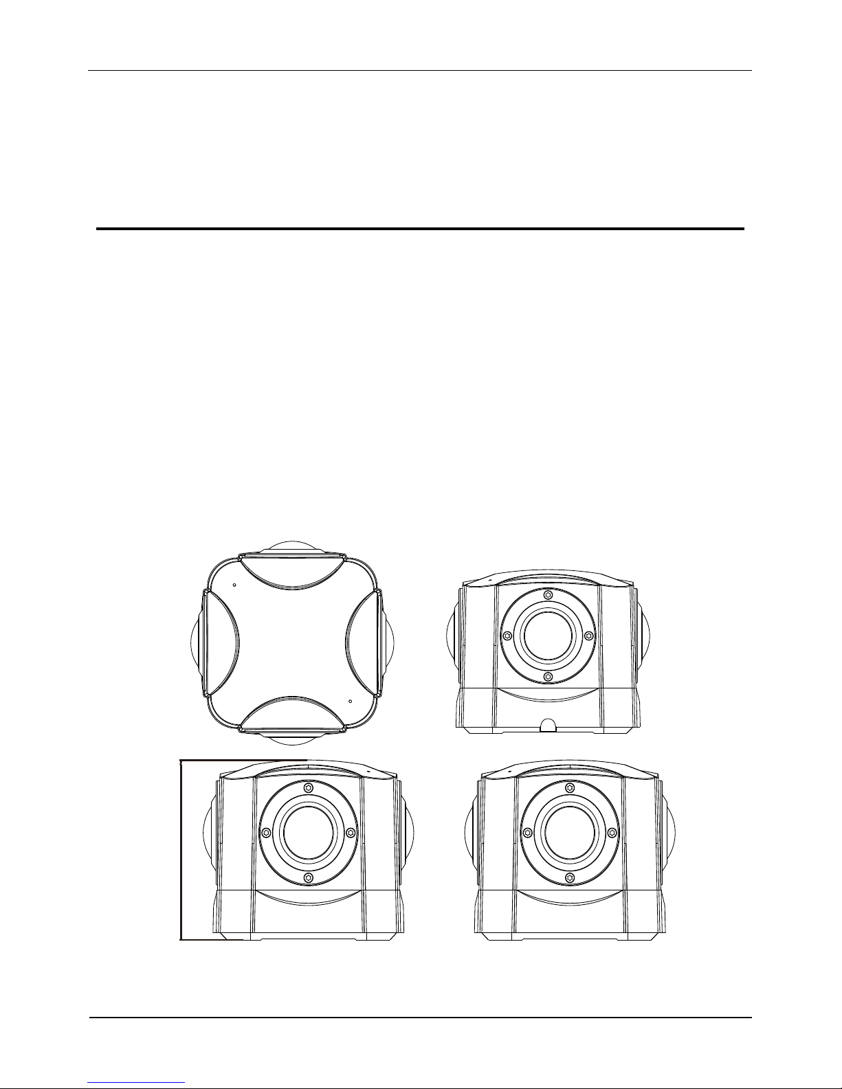
1.2 Device Structure
Figure 1-1 shows the rear panel of the Panoramic Security Surveillance Network Camera. For details
about the interfaces, see Table 1-1.
Figure 1-1 Appearance and interfaces of device
90
Panoramic Security Surveillance Network Camera
User Manual
Contents
Issue V1.0 (2019-01-28) 7
112.2
112.2
101.8
101.8
31
39.4
31
39.4
31
39.4
31 39.4
4-M8 * 6mm
Table 1-1 Interfaces
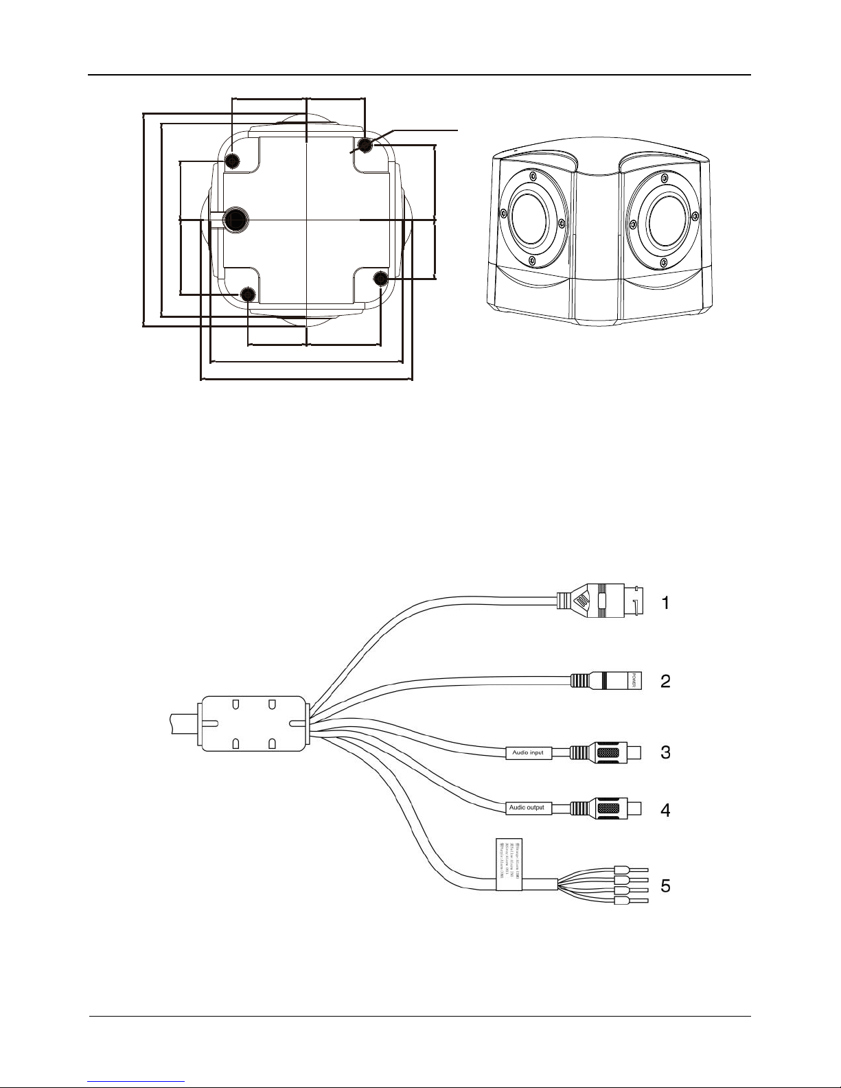
1.3 Cable Connection
Figure 1-2 the multi-connector combination cable of the network camera. For details
about the multi-connector combination cable, see Table 1-2.
Figure 1-2 Multi-connector combination cable

Contents
Panoramic security surveillance Network Camera
User Manual
8
Issue V1.0(2019-01-28)
Table 1-2 Multi-connector combination cable
NO.
Color
Port
Description
1
N/A
Network
access port
Connects to a standard Ethernet cable.
2
Power supply
port
Connects to a 12V direct current (DC)
power supply.
3
Audio input
port
Receives analog audio signals from
devices such as a sound pickup device.
4
Audio output
port
Connects to an external audio device
such as a speaker.
5
Gray core
Alarm output
terminal A
(normal open)
Alarm output
Purple core
Alarm output
terminal B
(normal open)
yellow core
Alarm input
positive
terminal
Alarm input terminal
Orange core
Alarm input
ground
terminal
1.4 Configuration Requirements
CPU: Intel(R) Core(TM) i7-8700 cpu @3.20GHz or later
RAM:16GB or more
Graphics card:GeForce GTX 1070 Ti or above。
Panoramic Security Surveillance Network Camera
User Manual
Contents
Issue V1.0 (2019-01-28) 9
2 Installation
2.1 Preparations
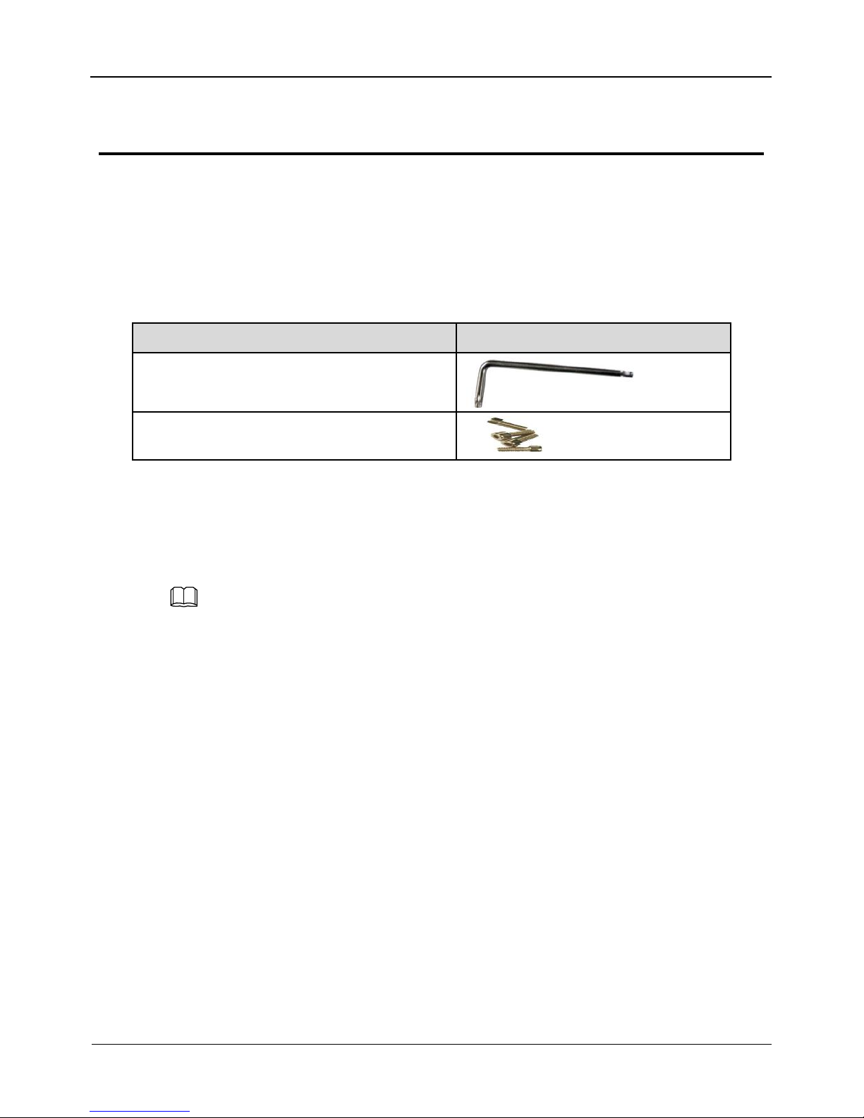
User need the tools and accessories shown in Table 2-1 during the installation (you
need to prepare the tools by yourself, and the accessories are in the package of the
camera).
Table 2-1 Installation tools
Tools
Appearance
L-Wrench (delivered with the camera)
Hexagon socket stainless steel
screw(delivered with the camera)
2.2 Installation Mode
If the camera is installed indoor, a bracket should be selected; if the camera is installed
outdoor, the shield and upright column should be selected.
NOTE
The bracket where the support is mounted must be able to withstand at least three times of
the total weight of the support and the camera.
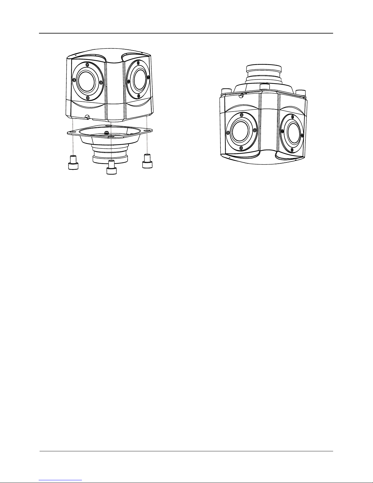
2.3 Installation Procedure
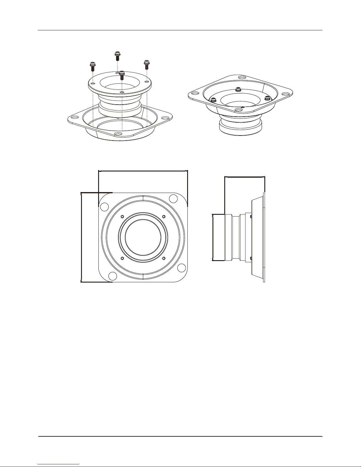
Step 1 Remove the installation block delivered with the camera. Fix the installation block on
the top or on the bottom of the camera, as shown in Figure 2-1.
Contents
Panoramic security surveillance Network Camera
User Manual
10
Issue V1.0(2019-01-28)
Figure 2-1 Fix the installation block
Figure 2-2 Dimension of bracket
91
91
41
φ 47
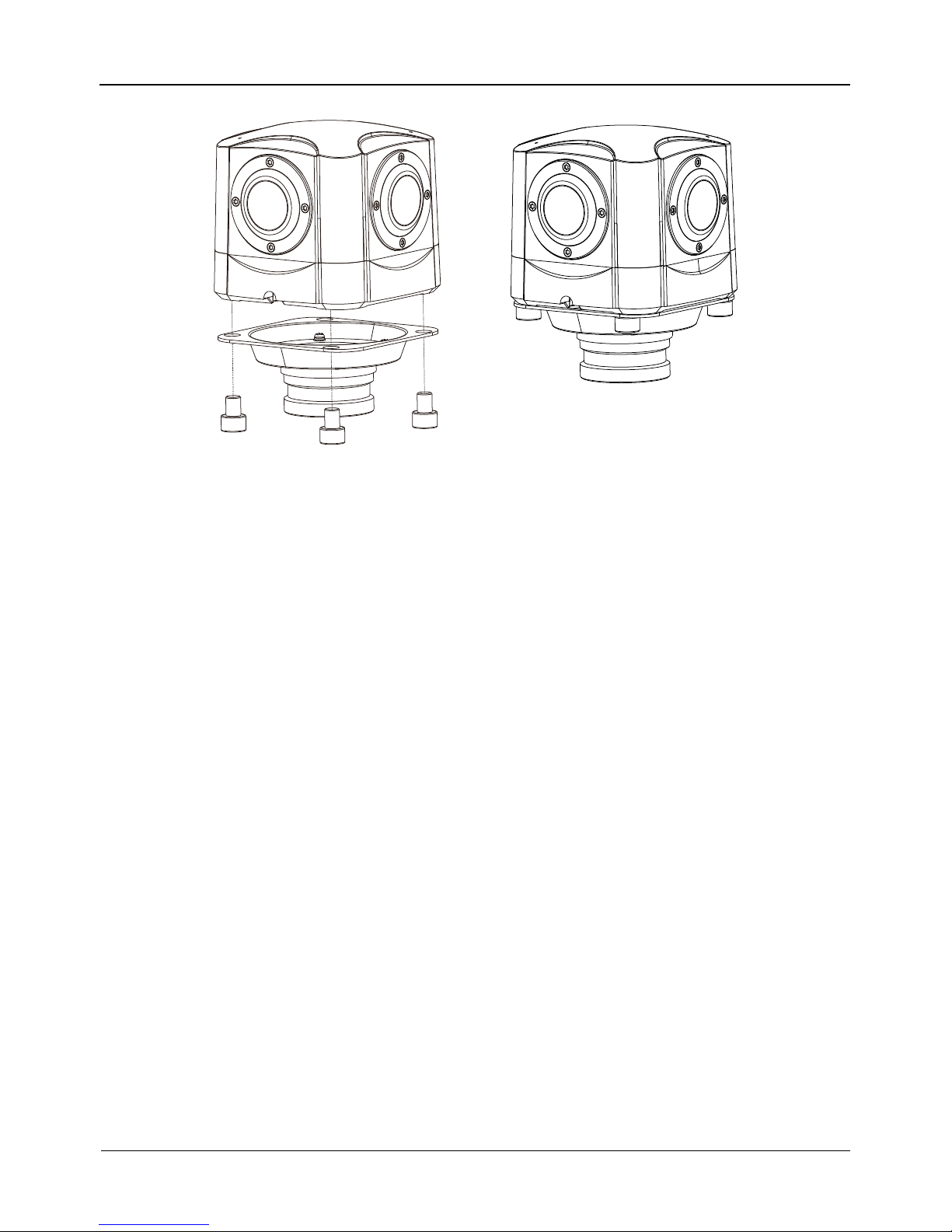
Step 2 Fix the mounting bracket on the pole, as shown in Figure 2-3.
Panoramic Security Surveillance Network Camera
User Manual
Contents
Issue V1.0 (2019-01-28) 11
Figure 2-3 Fix the mounting bracket
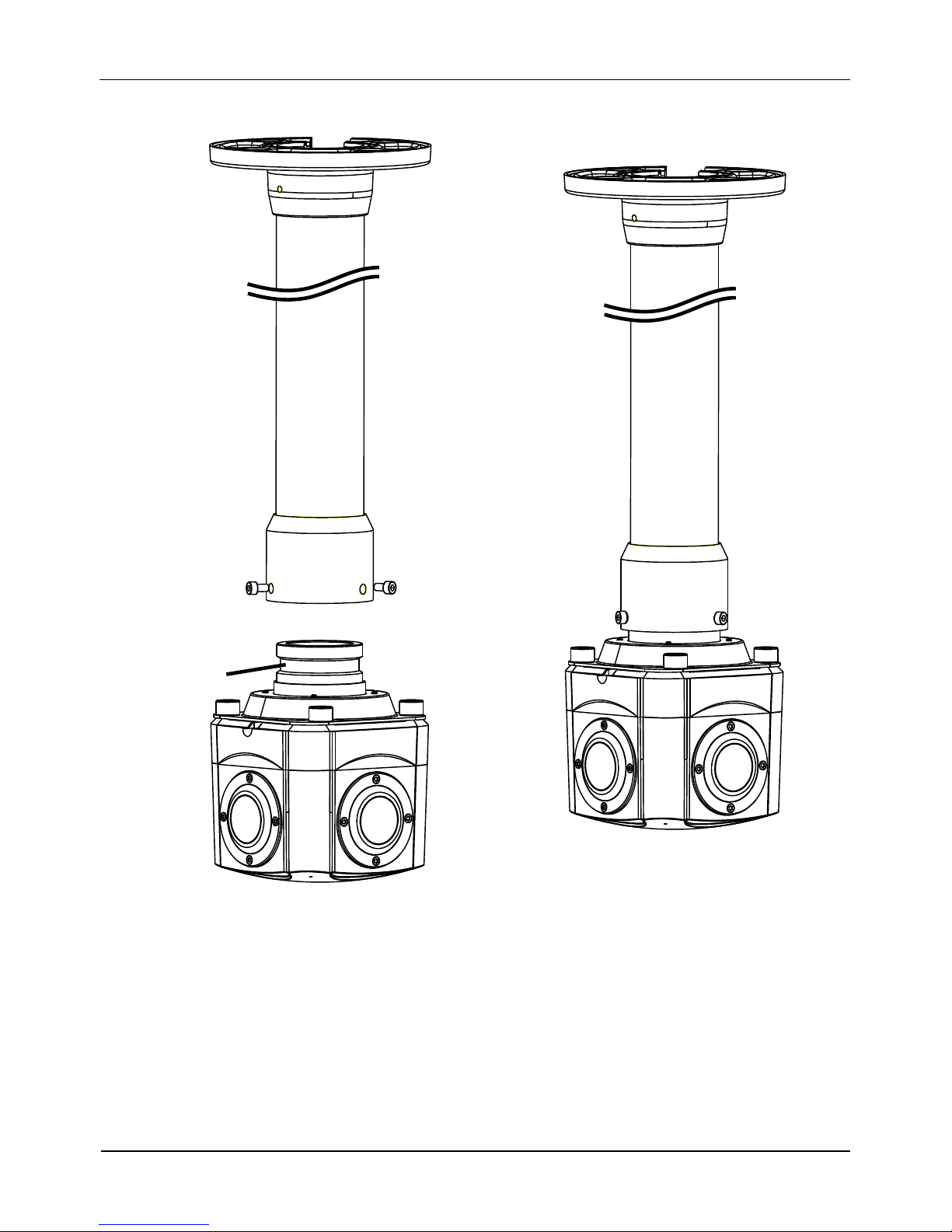
Step 3 ( Install with Column ) Align the camera adapter with the adapter hole on the column,
and when it is in place, fix the two with screws and confirm that fixing screw is fixed
in the groove of the adapter, as shown in Figure 2-4.
Contents
Panoramic security surveillance Network Camera
User Manual
12
Issue V1.0(2019-01-28)
Figure 2-4 Install with column
Groove
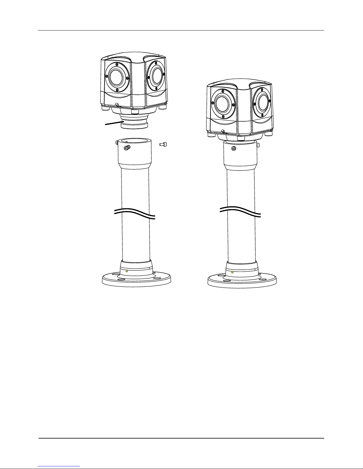
Step 4 ( Install on ceiling ) Fix the mounting bracket on the pole, as shown in Figure 2-5.
Panoramic Security Surveillance Network Camera
User Manual
Contents
Issue V1.0 (2019-01-28) 13
Figure 2-5 Fix the mounting bracket
Step 5 ( Install on ceiling ) Align the camera adapter with the adapter hole on the column, and
when it is in place, fix the two with screws and confirm that fixing screw is fixed in the
groove of the adapter, as shown in Figure 2-4.
Contents
Panoramic security surveillance Network Camera
User Manual
14
Issue V1.0(2019-01-28)
Figure 2-6 Install in ceiling
Groove
----End

Panoramic Security Surveillance Network Camera
User Manual
Contents
Issue V1.0 (2019-01-28) 15
3 Quick Configuration
3.1 Login and Logout
You must use Internet Explorer 8 or a later version to access the web management
system; otherwise, some functions may be unavailable.
Login system
Step 1 Open the Internet Explorer, enter the IP address of IP camera (default value:
192.168.0.120) in the address box, and press Enter.
The login page is displayed, as shown in Figure 3-1.
Figure 3-1 Login page
Step 2 Input the User and password.
The default name and password are both admin. Modify the password when you login
the system for first time to ensure system security. After modifying password, you need
to wait at least three minutes then power off to make sure modifying successfully . Or
login the Web again to test the new password.
You can change the system display language on the login page.
Step 3 Click Login button. The main page is displayed.
----End

Contents
Panoramic security surveillance Network Camera
User Manual
16
Issue V1.0(2019-01-28)
logout
To logout of system, click in the upper right corner of the main page, the login
page is displayed after you log out of the system.
3.2 Main Page layout
On the main page, you can view real-time video, set parameter, Video parameter, Video
control, and logout of the system. Figure 3-2 is shown the main page layout. Table 3-1
lists the elements on the main page layout.
Figure 3-2 Main page layout
1
2
3
4 5
6
7 8 9 10
11 12
13 14 15
Table 3-1 Elements on the main page
No.
Element
Description
1
Real-time video
area
Real-time videos are played in this area. User can also set
sensor parameters.
2
Playback
User can query the playback videos in this area.
NOTE

Panoramic Security Surveillance Network Camera
User Manual
Contents
Issue V1.0 (2019-01-28) 17
No.
Element
Description
Only when the SD card or NAS have videos that user can query
the playback videos.
3
Device
configuration
You can choose a menu to set device parameters,
including the device information, audio and video streams,
alarm setting, and privacy mask function.
4
Change
password
You can click to change the password.
5
Sign Out
You can click to return to the login page.
6
Stream
There are four streams. Choose one type from drop-down
list. Stream 4 is SVC stream.
7
Pause/Start
Close live video or play live video.
8
Live/Smooth
Switch image quality.
9
Audio
Open or close audio.
10
Interphone
Open or close interphone.
11
Sensor setting
Click the icon, it will access to sensor setting.
12
Snapshot
Click the icon, it will snapshot.
13
Local record
Click the icon, it will record video and save to local folder.
14
Mode
: Panoramic mode, fisheye
mode, crystal ball mode, prospective mode, planet mode, as shown in
figure 3-3 to figure 3-6.
15
Intelligent
analysis
Open or close intelligent analysis.
When the live video is full screen, user can use keyboard shortcuts to switch mode, F2
is for panoramic mode, F3 is for prospective mode, F4 is for crystal ball mode, F5 is
for fisheye mode, and F6for is planet mode.
The key A is for autorotation (tour),the key S is for stopping spinning.
1. When the device generates an alarm, the alarm icon is displayed. You can click
to view the alarm information. When the device accepts an alarm signal, the alarm icon will
display within 10s in the web management system.
2. When the device encounters an exception, the fault icon is displayed. You can click
to view the fault information.

Contents
Panoramic security surveillance Network Camera
User Manual
18
Issue V1.0(2019-01-28)
Figure 3-3 Prospective mode
Figure 3-4 Crystal ball mode
Figure 3-5 Fisheye mode
Figure 3-6 Planet mode
----End
3.3 Change the Password
Description
User can click to change the password for logging to the system.

Panoramic Security Surveillance Network Camera
User Manual
Contents
Issue V1.0 (2019-01-28) 19
Procedure
Step 1 Click in the upper right corner of the main page.
The Change Password dialog box is displayed, as shown in Figure 3-7.
Figure 3-7 Modify Password dialog box
The change password page will be displayed if you don’t change the default password when
you login the system for the first time. User need to wait at least three minutes after
changing password, and then restart the device. The password incorrect more than 3 times,
please login again after 5 minutes
Step 2 Input the old password, new password, and confirmation password.
Step 3 Click OK.
If the message "Change own password success" is displayed, the password is
successfully changed. If the password fails to be changed, the cause is displayed. (For
example, the new password length couldn’t be less than eight.)
Step 4 Click OK. The login page is displayed.
----End
3.4 Browse Video
User can browse the real-time video in the web management system.
Preparation
To ensure the real-time video can be play properly, you must perform the following
operation when you login to the web for the first time:
Step 1 Open the Internet Explorer. Choose Tools > Internet options > Security > Trusted
sites > Sites.

Contents
Panoramic security surveillance Network Camera
User Manual
20
Issue V1.0(2019-01-28)
In the display dialog box, click Add, as shown in Figure 3-8.
Figure 3-8 Add the a trusted site
Step 2 In the Internet Explorer, choose Tool > Internet Options > Security > Customer
level, and set Download unsigned ActiveX control and initialize and script ActiveX
controls not marked as safe for scripting under ActiveX controls and plug-ins to Enable,
as shown in Figure 3-9.
Figure 3-9 Configuring ActiveX control and plug-ins

Panoramic Security Surveillance Network Camera
User Manual
Contents
Issue V1.0 (2019-01-28) 21
Step 3 Download and install the player control as prompted.
The login page is display when the control is loaded.
3.4.1 Install Plugins
You will be prompted with a message “Download and install the new plugin” will show
as in Figure 3-10, when you login to the web management system for the first time.
Figure 3-10 Install plugin
Procedure
Step 1 Click the message, download and install the plugin follow the prompts.
Step 2 During installing, user should close the browser.
Step 3 Reopen the browser after installation.
----End
3.5 Setting Local Network Parameters
Description
Local network parameters include:
IP protocol
IP address
Subnet mask
Default gateway
Dynamic Host Configuration Protocol (DHCP)
Preferred Domain Name System (DNS) server
Alternate DNS server
MTU
Procedure
Step 1 Choose Configuration > Device >Local Network.
The Local Network page is displayed, as shown in Figure 3-11.

Contents
Panoramic security surveillance Network Camera
User Manual
22
Issue V1.0(2019-01-28)
Figure 3-11 Local Network page
Step 2 Set the parameters according to Table 3-2.
Table 3-2 Local network parameters
Parameter
Description
Setting
IP Protocol
IPv 4 is the IP protocol that uses
an address length of 32 bits.
IPv 6 is the IP protocol that uses
an address length of 128 bits.
[Setting method]
Select a value from the
drop-down list box.
[Default value]
IPv4
DHCP
The device automatically
obtains the IP address from the
DHCP server.
[Setting method]
Click the option button.
NOTE
To query the current IP
address of the device, you
must query it on the
platform based on the
device name.
DHCP IP
IP address that the DHCP server
assigned to the device.
DHCP function is
enabled.
IP Address
Device IP address that can be
set as required.
[Setting method]
Enter a value manually.
[Default value]
192.168.0.120

Panoramic Security Surveillance Network Camera
User Manual
Contents
Issue V1.0 (2019-01-28) 23
Parameter
Description
Setting
Subnet Mask
Subnet mask of the network
adapter.
[Setting method]
Enter a value manually.
[Default value]
255.255.255.0
Default Gateway
This parameter must be set if
the client accesses the device
through a gateway.
[Setting method]
Enter a value manually.
[Default value]
192.168.0.1
Preferred DNS
Server
IP address of a DNS server.
[Setting method]
Enter a value manually.
[Default value]
192.168.0.1
Alternate DNS
Server
IP address of a domain server.
If the preferred DNS server is
faulty, the device uses the
alternate DNS server to resolve
domain names.
[Setting method]
Enter a value manually.
[Default value]
192.168.0.2
MTU
Set the maximum value of
network transmission data
packets.
[Setting method]
Enter a value manually.
NOTE
The MTU value is range
from 800 to 1500, the
default value is 1500,
Please do not change it
arbitrarily.
Step 3 Click OK.
If the message "Apply success" is displayed, click OK. The system saves the
settings. The message "Set network pram’s success, Please login system again" is
displayed. Use the new IP address to log in to the web management system.
If the message "Invalid IP Address", "Invalid Subnet Mask", "Invalid default
gateway", "Invalid primary DNS", or "Invalid space DNS" is displayed, set the
parameters correctly.
If you set only the Subnet Mask, Default Gateway, Preferred DNS Server, and
Alternate DNS Server parameters, you do not need to login to the system again.
You can click Reset to set the parameters again if required.
----End

Parameter Setting
Panoramic Security Surveillance Network Camera
User Manual
24
Issue V1.0(2019-01-28)
4 Parameter Setting
4.1 Sensor Setting Interface
Operation Procedure
Step 1 On the Internet Explorer interface or the client software interface, select and right-click
the surveillance image to the set, as shown in Figure 4-1.
Figure 4-1 Sensor Setting
Table 4-1 Right-click setting parameters
Parameter
Description
Setting
Full screen
Click it, the live video will display in full screen
[Setting
method]
Click
Sensor
Set parameters of sensor, more details please
refer next chapters.
[Setting
method]
Click
Zoom In/
Zoom Out
N/A
[Setting
method]
Click
Restore
Panorama
When the live video is zoom in or out, click the
icon to restore.
[Setting
method]
Click
Step 2 Choose Sensor. The Sensor Configuration dialog box is displayed, as shown in
Figure 4-2.
----End

Panoramic Security Surveillance Network Camera
User Manual
Parameter Setting
Issue V1.0 (2019-01-28) 25
4.2 Time Segment
Figure 4-2 shows the time segment interface.
Figure 4-2 Time segment interface
Operation Procedure
Step 1 Click in the lower left corner of Sensor Setting, and choose Debug
Mode.
Step 2 Tick Enable.
Step 3 Set the Start Time
Step 4 Set the End Time
Step 5 Click Save, the message "Save success" is displayed, the system saves the settings.
----End
4.3 Image Setting
Figure 4-3 shows the image setting interface.

Parameter Setting
Panoramic Security Surveillance Network Camera
User Manual
26
Issue V1.0(2019-01-28)
Figure 4-3 Image interface
Table 4-2 lists the image setting parameters.
Table 4-2 Image setting parameters
Parameter
Description
Setting
Brightness
It indicates the total brightness of an image. As
the value increases, the image becomes
brighter.
[Setting method]
Drag the slider.
[Default value]
50
Sharpness
It indicates the sharpness of the image plane
and the sharpness of the image edge. The
shaper the image, the better detail contrast.
[Setting method]
Drag the slider.
[Default value]
50
Saturation
It indicates the color will be more gorgeous if
the value is higher.
[Setting method]
Drag the slider.
[Default value]
50
Contrast
It indicates the contrast between the bright part
and the dark part of an image. As the value
increases, the contrast increases.
[Setting method]
Drag the slider.
[Default value]
50
----End

Panoramic Security Surveillance Network Camera
User Manual
Parameter Setting
Issue V1.0 (2019-01-28) 27
4.4 Scene
Figure 4-4 shows the scene interface.
Figure 4-4 Scene interface
Scene: Indoor and Outdoor.
Mirror: Normal and Rotation
4.5 Exposure
Figure 4-5 shows the exposure interface.

Parameter Setting
Panoramic Security Surveillance Network Camera
User Manual
28
Issue V1.0(2019-01-28)
Figure 4-5 Exposure interface
Table 4-3 Exposure parameters description
Parameter
Meaning
Configuration
Method
Exposure Mode
The exposure modes include:
Auto: The system performs auto exposure based
on the monitoring environment.
Manual: You can adjust the brightness of an
image by setting the following three items:
Shutter Setting, Iris Setting and Gain Setting.
Shutter Priority: You can set Shutter Setting to
fixed values. The iris and gain are automatically
adjusted by the system.
[Setting method]
Select a value
from the dropdown list.
[Default value]
Auto
Meter area
It is used to select the metering area.
Whole: During metering, all areas of an image
have an equal weight, that is, all areas are
involved in the metering.
Center pot: During metering, the central pot of an
image has the highest weight.
Center Area: During metering, the middle area
(1/2 of the total area) of an image has the highest
weight, and other areas have the lowest weight.
[Setting method]
Select a value
from the dropdown list.
[Default value]
Whole

Panoramic Security Surveillance Network Camera
User Manual
Parameter Setting
Issue V1.0 (2019-01-28) 29
Max Shutter
The device automatically adjusts the shutter time
based on the ambient brightness. The shutter time is
less than or equal to the value of this parameter.
[Setting method]
Select a value
from the dropdown list.
[Default value]
1/25
Max Gain
The device automatically adjusts the gain based on the
external light. The gain is less than or equal to the
value of this parameter.
[Setting method]
Drag the slider.
[Default value]
50
4.6 White Balance
Figure 4-6 shows the white balance interface.
Figure 4-6 White balance interface

Parameter Setting
Panoramic Security Surveillance Network Camera
User Manual
30
Issue V1.0(2019-01-28)
Table 4-4 White balance parameters description
Parameter
Meaning
Configuration Method
Mode
It is adjusted based on application
scenarios to improve the fidelity of the
image color.
The WB modes include:
Auto: In automatic white balance
(WB) mode, the system
automatically performs white
balance based on the monitoring
environment.
Tungsten
Fluorescent
Daylight
Shadow
Manual: In manual WB mode, you
can manually select a WB mode
based on the monitoring
environment.
[Setting method]
Select a value from the drop-down
list.
[Default value]
Auto
Red Gain
It indicates the gain applied to red
channels. As the value increases, the
color temperature becomes lower.
This parameter is valid when Manual
Mode is set to Customized.
[Setting method]
Drag the slider.
[Default value]
0
Blue Gain
It indicates the gain applied to blue
channels. As the value increases, the
color temperature becomes higher.
This parameter is valid when Manual
Mode is set to Customized.
[Setting method]
Drag the slider.
[Default value]
0
4.7 DayNight
Figure 4-7 shows the DayNight interface.

Panoramic Security Surveillance Network Camera
User Manual
Parameter Setting
Issue V1.0 (2019-01-28) 31
Figure 4-7 DayNight interface
Table 4-5 DayNight parameters description
Parameter
Meaning
Configuration Method
D/N
Setting
Mode
It can be only set to Day Mode,
Day mode
The image is colored, and the filter is in
the day state, preventing infrared light
from entering the sensor.
[Default value]
Day Mode
4.8 Noise Reduction
Figure 4-8 shows the Noise reduction interface.

Parameter Setting
Panoramic Security Surveillance Network Camera
User Manual
32
Issue V1.0(2019-01-28)
Figure 4-8 Noise reduction interface
Table 4-6 lists the Noise reduction parameters.
Table 4-6 Parameters on the Noise reduction interface
Parameter
Description
Setting
2 DNR
Decrease the image
noise.
[How to set]
Select from the drop-down list box.
Drag the slider to adjust max
strength.
[Default value]
Auto
3 DNR
Decrease the image
noise.
[How to set]
Select from the drop-down list box.
Drag the slider to adjust max
strength.
[Default value]
Auto
----End
4.9 Enhance Image
Figure 4-9 shows the Enhance Image interface.

Panoramic Security Surveillance Network Camera
User Manual
Parameter Setting
Issue V1.0 (2019-01-28) 33
Figure 4-9 Enhance image interface
Table 4-7 Enhance image parameters description
Parameter
Meaning
Configuration Method
WDR
It is used to display the foreground and
background at the same time in the environment
with a large brightness difference. When the
brightness difference is larger, you can increase
the WDR level to obtain better image effect.
[Setting method]
Tick the WDR mode
and drag the slider.
[Default value]
50
HLC
It provides a clearer view of an image in the
highlight environment. When HLC is enabled, the
total brightness of an image is reduced, allowing
you to view objects in front of the highlight.
[Setting method]
Tick the HLC mode and
drag the slider.
[Default value]
50
BLC
It provides a clearer view of an image in the
backlight environment. When BLC is enabled, the
total brightness of an image increases, allowing
you to view objects in front of the backlight.
Meanwhile, the objects behind the backlight are
exposed excessively.
[Setting method]
Tick the BLC mode.

Parameter Setting
Panoramic Security Surveillance Network Camera
User Manual
34
Issue V1.0(2019-01-28)
DeFog
It provides a clearer view of an image in the
fogged environment when Defog is enabled.
As the value increases, the image becomes
clearer.
[Setting method]
Tick the Defog mode
and drag the slider.
[Default value]
50
----End

Panoramic Security Surveillance Network Camera
User Manual
Configuration
Issue V1.0 (2019-01-28) 35
5 Configuration
5.1 Device Information
User can set device name and view the information of camera on Device info interface.
Figure 5-1 Device information interface
Table 5-1 Device information
Parameter
Description
Setting
Device ID
Unique device identifier used
by the platform to distinguish
the devices.
[Setting method]
The parameter cannot be modified.

Configuration
Panoramic Security Surveillance Network Camera
User Manual
36
Issue V1.0(2019-01-28)
Device Name
Name of the device.
NOTE
The device name cannot
exceed 32 bytes or 10
simplified characters;
otherwise, the modification
fails.
[Setting method]
Enter a value manually.
MAC Address
N/A
[Setting method]
These parameters cannot be
modified.
Camera Type
Product Model
Manufacturer Name
Hardware Version
Firmware Version
Video Channel(s)
Channel Quantity
Alarm Input
Quantity
Alarm Output
Quantity
Serial Port Quantity
Network card
Quantity
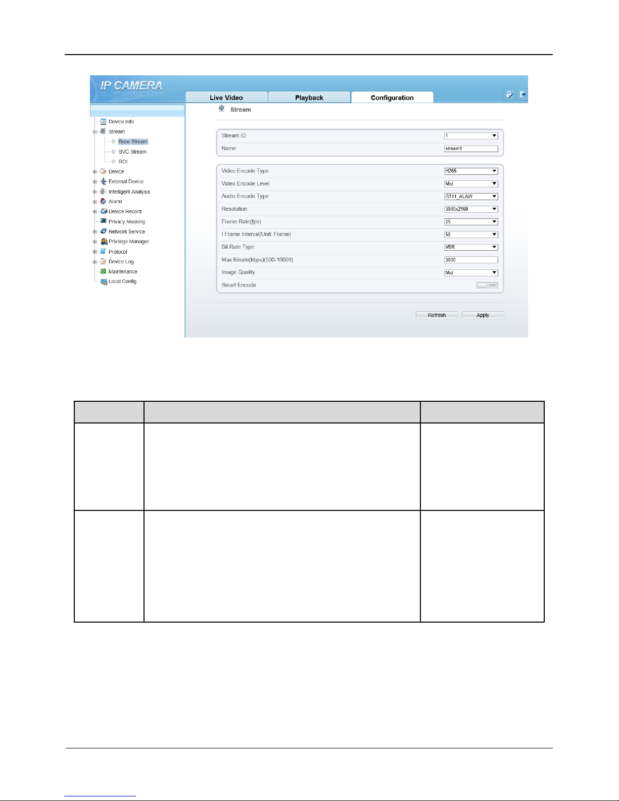
5.2 Stream
At stream interface, users can set Base Stream, SVC stream and ROI, as shown in
Figure 5-2.
Panoramic Security Surveillance Network Camera
User Manual
Configuration
Issue V1.0 (2019-01-28) 37
Figure 5-2 Stream interface
Table 5-2 Stream parameters description
Parameter
Description
Setting
Stream ID
The device supports two streams.
Streams 1 and 2 use the H.264 codec.
The maximum resolution can be set for streams 1.
Only a low resolution can be set for stream 2.
[Setting method]
Select a value from
the drop-down list
box.
Name
Stream name.
NOTE
The stream name is combined with Chinese character,
number, character and underline.
[Setting method]
Enter a value
manually. The value
cannot exceed 32
bytes.
[Default value]
stream1

Configuration
Panoramic Security Surveillance Network Camera
User Manual
38
Issue V1.0(2019-01-28)
Video
Encode
Type
The video codec determines the image quality and
network bandwidth required by a video. Currently,
the following codec standards are supported:
MJPEG
MJPEG is a standard intra-frame compression
codec. The compressed image quality is good. No
mosaic is displayed on motion images. MJPEG does
not support proportional compression and requires
large storage space. Recording and network
transmission occupy large hard disk space and
bandwidth. MJPEG is not applicable to continuous
recording for a long period of time or network
transmission of videos. It can be used to send alarm
images.
H.264
H.264 consists of H.264 Base Profile, H.264 Main
Profile, and H.264 High profile. The performance of
H.264 High Profile is higher than that of H.264 Main
Profile, and the performance of H.264 Main Profile is
higher than that of H.264 Base Profile. If a hardware
decoding device is used, select the appropriate codec
based on the decoding performance of the device.
H.264 High Profile has the highest requirements on
the hardware performance, and H.264 Base Profile
has the lowest requirements on the hardware
performance.
H.265
H.265 is the new video encoding standard ,it's the
improvement standard from H.264. H.265 improves
the streams, encoding quality and algorithm
complexity to make configuration as optimization.
[Setting method]
Select a value from
the drop-down list
box.
[Default value]
H.264 High Profile
NOTE
The H.264 High
Profile codec means
high requirements on
the hardware. If the
hard decoding
capability is low, use
H.264 Main Profile or
H.264 Base Profile.
Video
Encode
Video coding level is the level of the algorithm's
performance requirements for decoding hardware
devices.
H.264
Low:H264 Base profile
Mid:H264 Main Profile
High:H264 High Profile
H.265: Mid

Panoramic Security Surveillance Network Camera
User Manual
Configuration
Issue V1.0 (2019-01-28) 39
Audio
Encode
Type
The following audio codec standards are supported:
G711_ULAW: mainly used in North America and
Japan.
G711_ALAW: mainly used in Europe and other
areas.
RAW_PCM: codec of the original audio data. This
codec is often used for platform data.
[Setting method]
Select a value from
the drop-down list
box.
Resolution
A higher resolution means better image quality.
NOTE
IP cameras support the different resolutions based on the
model.
[Setting method]
Select a value from
the drop-down list
box.
Frame
Rate(fps)
The frame rate is used to measure displayed frames.
A higher frame rate means smoother videos. A video
whose frame rate is higher than 22.5 f/s is considered
as smooth by human eyes.
Frame rates for different frequencies are as follows:
50 Hz: 1–25 f/s
60 Hz: 1–30 f/s
NOTE
The frequency is set on the Device Configuration >
Camera page. The biggest MJPEG coding format frame
rate is 12 frames per second.
[Setting method]
Select a value from
the drop-down list
I Frame
Interval(F
rame)
I frames do not require other frames to decode.
A smaller I frame interval means better video quality
but higher bandwidth.
[Setting method]
Select a value from
the drop-down list
Bit Rate
Type
The bit rate is the number of bits transmitted per unit
of time.
The following bit rate types are supported:
Constant bit rate (CBR)
The compression speed is fast; however, improper bit
rate may cause vague motion images.
Variable bit rate (VBR)
The bit rate changes according to the image
complexity. The encoding efficiency is high and the
definition of motion images can be ensured.
[Setting method]
Select a value from
the drop-down list
box.
Max bit
Rate(500-
16000)
Indicates the maximal value of the bit rate.
[Setting method]
Enter a value
manually.

Configuration
Panoramic Security Surveillance Network Camera
User Manual
40
Issue V1.0(2019-01-28)
Image
Quality
The video quality the camera output.
[Setting method]
Select a value from
the drop-down list
box.
Smart
Encode
Smart Encode.
Smart encode includes H.264 & H.265.
The storage space will be reduced fifty percent
when smart encode is enable.
Only main stream supports smart encode.
[Setting method]
Click the button on to
enable Smart
Encode.
The SVC stream and ROI can be set when the Smart Encode is disabled.
5.3 Device
User can set Local Network, Device Port, Date and Time, Camera, OSD,
Microphone, System and Voice Denoise, as shown in Figure 5-3.
Figure 5-3 Device interface
Device Port:Control port, http port and RTSP port.
Date and Time: Time zone, daylight savings time, device time, current PC time, set
manually and NTP.
Camera: Channel name, video system and video refresh frequency.

Panoramic Security Surveillance Network Camera
User Manual
Configuration
Issue V1.0 (2019-01-28) 41
OSD: Time, custom OSD (at most 8 reminders can be set), advanced settings (time
format, font color, font size, font transparency, font on lighted back and device name).
Microphone: Microphone type and volume.
System: Language of OSD, Web mode.
Voice Denoise: enable or disable the function.
5.4 Intelligent Analysis
User can set Perimeter, Single Virtual Fence, Double Virtual Fences, Loiter, Multi
Loiter, Object Left, Object Removed, Abnormal Speed, Converse, Illegal Parking,
Signal Bad and Advanced, as shown in Figure 5-4.
Figure 5-4 Intelligent analysis interface
If user wants to enable intelligent analysis, he needs to enable the function and set
schedule respectively.
5.5 Alarm
User can set Alarm Output, Disk Alarm, Network Alarm, I/O Alarm Linkage,
Motion Alarm, and Push Message, as shown in Figure 5-5.

Configuration
Panoramic Security Surveillance Network Camera
User Manual
42
Issue V1.0(2019-01-28)
Figure 5-5 Alarm interface
User set parameters of alarm when you need.
5.6 Device Record
User can set Record Policy and Record Directory on device record interface, as
shown in Figure 5-6.

Panoramic Security Surveillance Network Camera
User Manual
Configuration
Issue V1.0 (2019-01-28) 43
Figure 5-6 Device record interface
5.7 Privacy Masking
User can set at most four privacy masking areas, as shown in Figure 5-7.Dragging the
mouse cursor to choose area to mask, click Add to save the area.
Figure 5-7 Privacy masking interface

Configuration
Panoramic Security Surveillance Network Camera
User Manual
44
Issue V1.0(2019-01-28)
5.8 Network Service
User can set 802.1X, DDNS, PPPoE, Port Mapping, SMTP, FTP, IP Filter, CGI
Alarm Service Center and SNMP at network interface, as shown in Figure 5-8.
Figure 5-8 Network service interface
User set the network parameter according to network knowledge. Click Apply to save
the settings.
5.9 Privilege Manager
User can add the new user accounts, modify or operate the authority of user, as shown
in Figure 5-9.

Panoramic Security Surveillance Network Camera
User Manual
Configuration
Issue V1.0 (2019-01-28) 45
Figure 5-9 Privilege manager interface
5.10 Protocol
User can set Protocol Info, Security, CMS Configuration and Multicast Param, as
shown in Figure 5-10.
Figure 5-10 Protocol interface

Configuration
Panoramic Security Surveillance Network Camera
User Manual
46
Issue V1.0(2019-01-28)
5.11 Device Log
User can view the Operation Log and Alarm Log, Collect All Log, as shown in
Figure 5-11.
Figure 5-11 Device log interface
5.12 Maintenance
User can Restart, Update and Restore to Factory Default, as shown in Figure 5-12.
Figure 5-12 Maintenance interface

Panoramic Security Surveillance Network Camera
User Manual
Configuration
Issue V1.0 (2019-01-28) 47
5.13 Local Config
User can set local configuration such as Snapshot picture format, Snapshot Save
Path, Local Record Save Path, Local Record File Size and Hardware Decode, as
shown in Figure 5-13.
Figure 5-13 Local config interface
----End

Technical Specifications
Panoramic Security Surveillance Network Camera
User Manual
48
Issue V1.0(2019-01-28)
6 Technical Specifications
Table 6-1 lists the specifications of the camera.
Table 6-1 Technical specifications
Type
Parameter
Description
Camera
performance
Pixel
Single lens is 8 MP, four lens joint is
32 MP(8k)
Video feature
Optional, PAL or NTSC (the default
value is PAL)
Effective pixel
7680*4320
Field angle
V 360°* H 360°
Digital zoom
Support
The lowest illumination
Color: 0.002 Lux@(F 2.2,AGC
ON)
DayNight
Color
Optical filter
Support fixed
IR distance
N/A
Shutter speed
1/5 s~1/20K s
Gain control
Manual / Auto (the default value is
auto)
White balance
Manual / Auto (the default value is
auto)
Correction of lens
aberration
Support
WDR
Support digital WDR
HLC
Support
BLC
Support
Digital image stabilization
Support
Lens
Prime lens
Customization φ12mm fisheye lens

Panoramic Security Surveillance Network Camera
User Manual
Technical Specifications
Issue V1.0 (2019-01-28) 49
Type
Parameter
Description
features
Focal length of lens
2.2 mm
F value
2.2
F OV
190°
External
interface
Network interface
RJ-45, 10/100Base-T self-adaptive
Ethernet port, support POE apply,
conform to 802.3 AT
Power supply
DC12V/ PoE +
RS485
N/A
Fiber optic interface
N/A
Alarm interface
One alarm input and one alarm
output
Audio interface
one audio input, one audio output
Microphone
Double Mic
Stereo
Support
Two-way voice
Support
CVBS interface
N/A
SD card interface
Reserved
Reset
Restore factory settings
Video
features
Video encode format
H .264/ H .265/MJPEG
Multiple code streams
4 streams (the forth is sub stream,
support preview and record )
Image setting
Brightness, contrast, saturation,
sharpness
Bit rate format
CBR/VBR
Synchronous mode
Inter-sync
SNR
≥ 55 dB
DNR
Auto/manual(support for 2D and 3D
noise reduction)
Audio
features
Audio encoding format
Support for G711
Audio bit rate
64kbps(G.711), 128kps
(RAW_PCM)
Network
features
Front-end access protocol
ONIVF, GB/T 28181,Third-part
protocol

Technical Specifications
Panoramic Security Surveillance Network Camera
User Manual
50
Issue V1.0(2019-01-28)
Type
Parameter
Description
Network protocol
IPv4/ Ipv6, RTSP/RTP/RTCP,
TCP/UDP, HTTPS, DHCP, DNS,
DDNS, PPPoE, SMTP
Heartbeat mechanism
Support
Wireless network
N/A
Streaming mode
Unicast
Number of users in
concurrent access
10
SNMP
Support
Automatic device discovery
Support
Function
Intelligent analysis
Support
Preview video mode
Tile 360°,perspective mode, crystal
ball mode, planet mode, auto-rotation
mode.
Defog
Support
ROI
Support
Time segment
Support
IO alarm detection
Support
Privacy mask
Support
Character display
Time, date, name and user-defined
characters
Security
Password protection, multi-level user
group management, user-define
permissions, and one-key reset
Reliability
Provide software and hardware
watchdogs and automatic fault
recovery
User authority
Two class, administrator and general
users. The administrator can assign
various permissions to general users
Support SDK development
Linux C /windows C & C++ SDK

Panoramic Security Surveillance Network Camera
User Manual
Technical Specifications
Issue V1.0 (2019-01-28) 51
Type
Parameter
Description
Storage
Local storage type
N/A
Capacity
N/A
SD card availability
N/A
Remote storage
N/A
WEB
applications
Language
Support 10 languages; Chinese is
default value, English, Spanish,
Portuguese, Polish, Italian, Russian,
French, Hungarian, Czech.
Support browsers
Windows IE 8 or later version,
Firefox,Chrome
Manager and maintenance
Not Supported Web upgrade,
separate upgrade tools
Web interface style
Customization/standard
Other
Power supply
DC 12 V/ POE+
Operating temperature
-40C to +60C
Operating humidity
RH 90% MAX (no condensation)
EMC level
Conform to CE/FCC and ministry of
public security standard
Protection level
IP66
Dimensions
112.2*112.2*90 mm(without
bracket)
Weight
About 1175 g (without bracket)
 Loading...