


SILVANTIS®
PHOTOVOLTAIC
MODULES
F-SERIES and R-SERIES
72-Cell High Wattage Modules
INSTALLATION GUIDE

F-SERIES and R-SERIES 72-Cell Installation Guide
1.0 Introduction
1.0 Introduction 2
1.1 Models Covered by Installation Guide 2
2.0 Safety 3
2.1 General Safety 3
2.2 Mechanical Safety 3
2.3 Electrical Safety 3
3.0 Mechanical Installation 4
3.1 Planning and Design 4
3.2 Module Installation Options 5
3.3 Module Installation Using Center
Mounting Brackets 5
3.4 Additional Mounting Methods 7
4.0 Electrical Installation 8
4.1 Planning and Design 8
4.2 Module Wiring 8
4.3 Grounding 9
4.3 Option A: Metal Lug 10
4.3 Option B: Racking Manufacturer
Integrated Grounding Methods 11
4.3 Option C: Bolt Wire Assembly 11
4.3 Option D: Alternative Grounding 11
5.0 Maintenance 12
5.1 String Grounding 12
6.0 Disclaimer of Liability 13
7.0 Appendix 14
7.1 Module Details 14
7.2 Center Clamp Module Installation
Illustrations 15
7.3 Module Clamp Drawings 15
Thank you for choosing SunEdison's Silvantis modules. This
guide provides information regarding the proper installation
and handling of Silvantis modules.
Silvantis modules consist of a series of electrically
interconnected monocrystalline solar cells that are sealed
within a laminated sheet of tempered, low glare antireflective coating (ARC) glass superstrate, and EVA back
sheet substrate. These laminates are secured inside an
aluminum frame to provide rigidness and a mounting
mechanism to affix to sub-structures. Do not modify or
remove frames.
Please review all the sections that pertain to proper
installation of modules listed in this guide. The instructions
detailed in this guide must be followed throughout the
module’s lifetime deployment. If you need additional
information about the safe, proper use and handling of
SunEdison photovoltaic module products, please contact
SunEdison.
1.1 Models Covered by Installation Guide
Silvantis Monocrystalline Modules
Silvantis F-Series
F310BzC F315BzC F320BzC
F325BzC F330BzC F335BzC
Silvantis F-Series U.S. Tariff-Free
F310BzD F315BzD F320BzD
F325BzD F330BzD F335BzD
Silvantis R-Series
R330BzC R335BzC R340BzC
R345BzC R350BzC R355BzC
z indicates manufacturing location: M = Malaysia, X = Mexico, K = Korea
P = China, T = Taiwan
For product parameters and specifications see Section 7.0.
© 2015 SunEdison 2

2.0 Safety
Ensure to follow all safety guidelines stated below. Failure
to do so can cause injury, damages, or a void in the
module warranty.
2.1 General Safety
• Modules are intended for outdoor use.
• Do not submerge modules in water at any time.
• The front and back of each module is labeled with
a product bar code. Do not cover, remove or deface
labels as they are necessary for product identification.
• Do not allow unauthorized persons near the installation
site or module storage area.
• Troubleshooting should include planning, checking,
disconnecting, cause seeking, replacement and
record keeping.
• Do not wear rings, jewelry, watches or other metallic
items while working with photovoltaic modules.
2.2 Mechanical Safety
• Damage to the glass surface or its anti-reflective coating
will impact the power output and overall efficiency of the
system. Scratches, handling marks or any other damage
to the glass surface must be avoided.
• To avoid these and other performance prohibitive
issues, keep the front side of the module clean and free
of obstructions including covers, tape, adhesives, paint
and debris.
• Packaged modules must be stored indoors; in a dry and
ventilated area.
• Once opened, continue to store modules in a dry and
ventilated room.
• To safely keep modules stored, they must remain
packaged on the provided pallets, and must not be
stacked more than two pallets high.
• Do not place or drop objects on the modules, including
other modules.
• Do not twist the module frame.
• Do not stand, step, walk or jump on the module.
• Do not mark the modules with sharp instruments.
• Do not leave a module unsupported or unsecured.
• Do not modify module in any way, which includes the
frame, glass, eva, etc.
• Upon unpacking, only carry a module by its frame with
two or more people. Do not carry a module by the wires
or junction box.
• All modules are manufactured with a sealed junction
box, pre-attached cables and locking connectors. These
components should not be modified or tampered with
in any way. If connectors are not hooked up right away,
SunEdison recommends attaching protective caps to
prevent damage to the connectors.
• Do not install or handle the modules or their
components when they are wet or during periods
of high wind.
• Do not attempt to disassemble, repair or open
any part of the module; including the junction box
or sub-components.
• Do not artificially concentrate sunlight on a module.
• Do not install or handle broken modules. If a module
is broken, or the back sheet is torn, contact with the
surface or frame can cause an electrical shock.
2.3 Electrical Safety
• All installations must be performed in compliance
with all applicable regional and local electrical codes
or other applicable national and international electrical
standards.
• Use only insulated tools during installation,
troubleshooting and maintenance of the modules.
• Wear suitable protection to prevent direct contact with
module’s electrical output and mechanical sharp edges.
• Cover the front of the modules with an opaque material
to stop production of electricity when installing or
working with a module or wiring.
WARNING: Precautions should be taken to avoid damage to the glass surface when unpacking, handling or
storing the modules since any damage to the glass surface may impact the power output of the modules.
© 2015 SunEdison 3

F-SERIES and R-SERIES 72-Cell Installation Guide
• Modules connected in a series should not be
disconnected under illumination. Disconnecting
modules under illumination may cause electrical arcing,
which may result in burns, fires or other injuries and
damages.
• Photovoltaic modules produce DC electrical energy
from sunlight. When illuminated, each module can
have a DC potential of over 45 V and should be
handled with care.
• Always use a wire management system that keeps
wires and cables out of direct contact with edged
surfaces, which could cut or damage the insulation. Do
not allow wires to rest on the ground or roof surface.
3.0 Mechanical Installation
3.1 Planning and Design
• Before installation, check to ensure the sub-structure
will accommodate expected system loads. This
includes and is not limited to roof, foundations,
mechanical structure and mechanical connections.
• All Silvantis solar modules have a module fire resistance
rating of Class C. According to the UL1703 test
protocol, revised in 2014, all Silvantis solar modules
also have a module fire resistance rating of Class A
for spread of flame, and fire performance of either
Type 1 or Type 2 classification as specified on the
module label. Per UL, the fire rating of this module is
valid only when mounted in the manner specified in
the mechanical mounting instructions. The system fire
rating is determined by the module, rack and roofing
materials. SunEdison recommends not mixing module
fire performance type within a system.
• Mechanical structures should not contact the module
back sheet, any racking or the microinverter under any
expected load conditions.
• Consider the following factors during system design,
which will influence performance:
a. SunEdison solar modules produce the most
power when they are pointed directly at the
sun, and should be tilted for optimum system
performance.
b. Proximity to obstructions have the potential to
shade or damage the modules (examples below):
• walls
• buildings
• trees
• groundcover
• snow cover
• dust and debris
c. Designs should allow adequate airflow across
the back of the module because elevated
temperatures will decrease energy yield.
d. Allow a minimum spacing of 10 mm between
modules for thermal expansion.
© 2015 SunEdison 4

3.2 Module Installation Options
For bolt and clamp mounting locations and allowable load
capacities, please refer to the table on pages 6-7.
• Each module should be mounted using four bolts
through the mounting holes on the rear side of the
module, or with four clamps over the front side, within
the region specified as shown in the mounting diagram
below.
• Depending on the desired load capability of the array,
modules may be mounted either perpendicular or
parallel to the structure rails. Clamps can be mounted
anywhere inside of the safe mounting range for each
case illustrated in the table on pages 6-7.
• If using bolts, use a bolt stack no smaller than ¼"-20
or M6, with two flat washers and a locking washer as
shown in Appendix 7.1.
• To ensure an adequate clamping area, all clamps must
be able to clamp within the range specified in the table
on pages 6-7. All fasteners used to fix the modules with
clamps should be no smaller than ¼”-20 or M6.
• To provide adequate fixing or clamping force, torque the
fasteners to the manufacturers torque specifications.
• For all cases, the area of the supporting structure in
contact with rear side of the module must comply with
the dimensions specified in Appendix 7.1.
• All other structural dimensions, such as clamp and rail
thickness, should be sized appropriately for the intended
site load.
3.3 Module Installation Using Center
Mounting Brackets
• Modules may also be mounted using center clamps as
shown in Appendix 7.2, for use with trackers.
• Center mounting clamps must meet SunEdison
approved extrusion and hardware requirements.
• For module loads higher than 2400 Pa, module clamps
and hardware must be pre-approved by SunEdison.
• SunEdison approved center clamps utilizing M8 bolts
are to be tightened to 9.2-11.9 N·m (6.8-8.8 ft·lbs).
• Mechanical structures should not contact the module
backsheet under any expected load conditions.
• Ensure that frame weep holes (see Appendix 7.1) are
not obstructed by the mechanical installation.
• Mechanical installation of the module shall not cause
the frame to torque more than 38 mm.
• A minimum clearance of 152 mm is required between
the roof and bottom of the module frame.
© 2015 SunEdison 5

F-SERIES and R-SERIES 72-Cell Installation Guide
A
A
C
C
B
C
B
FIGURE 1(a): MOUNTING CONFIGURATIONS
MODULE
ILLUSTRATION
FRONT VIEW
BACK VIEW
CASE 1
Bolt Mount
Locations
Clamp Mount
Locations:
Fixed clamp
location for
5400 Pa
front load
FRONT VIEW
BACK VIEW
CASE 2
Bolt Mount
Locations
Clamp Mount
Locations:
Clamp mount
allowable
range
CASE 3
Clamp Mount Locations:
Clamp mount allowable range
Case 3, option 1
BACK VIEW
OR Case 3, option 2
BACK VIEW
LOAD
PARAMETERS
DETAILS
Maximum
Rear Load:
2400 Pa
(50 psf)
Maximum
Front Load:
5400 Pa
(113 psf)
CASE 1: Structural rails
running perpendicular to
the length of the module
should be fixed via bolts at
the mounting holes between
each long side frame, or
Clamps can be mounted
at the Fixed Clamp Mount
location as shown in the
color code key. See 7.3 for
minimum clamp dimensions.
Maximum
Rear Load:
2400 Pa
(50 psf)
Maximum
Front Load:
5400 Pa
(113 psf)
CASE 2: Structural rails
running parallel to the
length of the module should
be fixed via bolts at the
mounting holes on each
long side frame, or Clamps
can be mounted anywhere
within the Clamp Mount
Range as shown in the color
code key.
Maximum
Rear Load:
2400 Pa
(50 psf)
Maximum
Front Load:
2400 Pa
(50 psf)
CASE 3: Structural rails
running perpendicular to the
length of the module should
be fixed via bolts at the
mounting holes between each
long side frame, or Clamps
can be mounted anywhere
within the Clamp Mount
Range as shown in the color
code key.
Mounting Color Code: Mounting Hole Location Module Rail Fixed Clamp Mount Clamp Mount Range
Fixed Clamp Mount location:
Clamp mount allowable range:
A – 394 mm
B – 248 mm
C – 444 mm
© 2015 SunEdison 6

FIGURE 1(b): MOUNTING CONFIGURATIONS
AP90 V1.5/ATI TRACKER
MOUNTING
CASE 4: Structural rails running parallel
to the length of the module should be
attached within the Mounting Range
on each long side frame as shown in
the color code key.
NEXTRACKER CENTER
MOUNTING WITH BOLTS
CASE 5: The NexTracker mounting
structure is authorized for use with
SunEdison PV modules. Special
mounting holes have been provided
on the long rail of the module frame as
shown in Appendix 7.1. Use of these
mounting holes for anything other than
NexTracker is prohibited.
Maximum
Rear Load:
2400 Pa (50 psf)
Maximum
Front Load:
2400 Pa (50 psf)
Maximum
Rear Load:
2400 Pa (50 psf)
CASE 5 CASE 4
Maximum
Front Load:
2400 Pa (50 psf)
Mounting Color Code: Mounting Hole Location Mounting Range Module Rail
D – 400 mm E – 1,188 mm F – 200 mm
3.4 Additional Mounting Methods
Use of the PanelClaw system (Polar Bear® III) is
recommended with Silvantis modules. Structures
manufactured by PanelClaw Inc. use a special clamp, or
Use of the SunEdison AP90 Single Axis Tracker is
authorized for use as well. Please refer to the AP90
installation guide for specific instructions. Installation
guides can be found on the SunEdison website.
"claw" designed to attach to the flange of the module at all
four corners, on the two short frame ends.
For proper placement, attach a claw over the module
frame flange at each of the four designated locations and
tighten the screw so that the claws are flush with the
long and short ends of the module flange. This mounting
method has been tested to a maximum rating of 50 psf in
the negative and positive direction. Refer to case two in
Figure 1(a), as well as the PanelClaw installation guide for
information on the installation of the clamps.
© 2015 SunEdison 7

F-SERIES and R-SERIES 72-Cell Installation Guide
4.0 Electrical Installation
4.1 Planning and Design
All modules are manufactured with a sealed junction
box, pre-attached cables and locking connectors. These
components should not be modified or tampered with
in any way.
Note: Installers shall ensure that the polarized locking
connectors are from the same supplier. Do not mix
polarized interlocking connectors from different
manufacturers—including connections at the inverter,
combiner boxes and modules. Doing so will void the
warranty. Refer to the corresponding data sheet for
connector types.
• Ensure connectors are clean and dry before
establishing connection.
• Ensure that all wire, fusing and disconnects are
appropriately sized for the system design according
to national, regional, and local codes.
• Electrical characteristics are within plus or minus 5% of
rated values for Isc, Voc, Impp and Vmp. Pmax ranges
between 0% to +3% (R-Series) and 0 W to +5 W
(F-Series) of rated Pmax at standard test conditions
(STC). However, modules will operate under conditions
that may be significantly different than STC. SunEdison
suggests multiplying specified ratings by a minimum of
1.25 or more when designing the system and balance
of system components. Refer to local codes before
planning and designing the system.
• Determine the maximum number of modules that may
be connected in series using the following formula
Ns = Vmaxs/Vocm
Where:
Ns equals the maximum modules in series.
Vmaxs equals the maximum system voltage.
Please refer to module data sheet for actual Vmax
rating, as some models are rated for 1000 V UL and
1000 V IEC.
Vocm equals the module open circuit voltage at
coldest conditions for the site (refer to local codes).
4.2 Module Wiring
• The module includes wires and polarized locking
connectors from the junction box on the back of the
module. Field replacement of connectors or cables
must be avoided and will void the product warranty.
Polarized locking connectors of the same type, make
and manufacturer are required for all series string
wiring. The maximum operating temperature of the
wires and connectors should not exceed 85 C.
• When installing modules in landscape orientation, use
the 1.3 meter lead lengths to ensure enough cable
length to make adjacent module-to-module string
connections (assumes a maximum spacing of 50 mm
between adjacent modules).
• Always wire modules so that proper polarity is
maintained. Avoid placing excessive tension on
the cables.
• There is no limit to the maximum number of series
strings that can be combined in parallel. However,
each string must include overcurrent protection with a
maximum rating of 15 A. SunEdison recommends the
use of DC rated fuses or overcurrent protection devices
with the appropriate maximum voltage rating.
• Do not connect modules directly to a parallel bus.
• The cross-sectional areas of cable and the connector
type must be selected to align with the overall system
design, and should include the maximum short
circuit current of the system, maximum operating
temperatures and cable run lengths.
• For field connections, use at a minimum #12 AWG/4
mm2 wires; insulated for a minimum of 85 C. Use
copper wire only.
WARNING: Installers shall adhere to all applicable local, regional, and national codes and regulations when designing
and constructing the photovoltaic system
Note: In colder climates, it may be necessary to further reduce the maximum number of modules in a series by using
Vocm at the minimum expected operating temperature.
© 2015 SunEdison 8

4.3 Grounding
Module frames and structures grounding must be
compliant with all national and local regulations.
SunEdison recommends grounding all module frames
and associated structures in order to maintain a zerovoltage potential between the electrically conductive
equipment and the earth in all scenarios.
SunEdison modules use a coated aluminum frame
for corrosion resistance. In order to ensure proper
grounding the coating must be penetrated by the
grounding method. A copper grounding wire with a
minimum gauge of 12 AWG is recommended to carry
the electrical ground load. Consult applicable codes
to ensure the appropriate conductor diameter is used
for the system. The grounding method must not allow
direct contact of dissimilar metals with the frame of the
module, as this would result in galvanic corrosion. UL
1703 recommends metal combinations not to exceed a
voltage potential of 0.5.
The frame has predrilled holes marked with a grounding
sign as illustrated in Figure 2. These holes should be used
exclusively for grounding. Do not drill additional holes
or modify existing holes in the frame.
Figure 2: Image of the grounding holes
© 2015 SunEdison 9

F-SERIES and R-SERIES 72-Cell Installation Guide
4.3 Option A: Metal Lug
SunEdison recommends copper or tin plated grounding
lugs rated for outdoor use and used with a #12 or
larger wire. The use of a copper split bolt connector is
authorized for well.
Attach the grounding lug to the frame by referring to
Figure 3 and the following steps:
Figure 3: Option A Grounding Lug Assembly
Use stainless steel metric or English sets only. Please
refer to the following list for the minimum hardware
requirements for each set.
Metric set
- Stainless Steel Bolt M4
- Stainless Steel Nut M4
- Stainless Steel Flat Washer M4
- Stainless Steel Spring Washer M4
- Stainless Steel Lock-Toothed Washer M4
- Stainless Steel Slotted Washer M4
English set
- Stainless Steel Bolt #8-32
- Stainless Steel Nut #8-32
- Stainless Steel Flat Washer #8-32
- Stainless Steel Spring Washer #8-32
- Stainless Steel Lock-Toothed Washer #8-32
- Stainless Steel Slotted Washer #8-32
Step 1: Place the grounding lug over the grounding hole
on the exterior of the module frame.
Step 2: Place a star washer directly between the bottom
of the grounding lug and the exterior surface of
the frame.
Step 3: Place a bolt through the lug, star washer and
frame grounding hole.
Step 4: Secure the lug to the frame using a flat washer,
split washer and nut.
Step 5: Torque the bolt stack to approximately 1.5
N·m (1.1–1.7 ft·lbs) to ensure the star washer
penetrates the anodized frame.
–2.3
© 2015 SunEdison 10

4.3 Option B: Racking Manufacturer
Integrated Grounding Methods
Integrated grounding methods must be appropriately
certified to UL standards and must be in accordance
with the specified instructions of the respective
manufacturer. SunEdison modules can be grounded
by bonding modules to a grounded racking system.
SunEdison recommends using its internally developed
integrated grounding clip, PN: 720256 with its piloted
bolt, PN: 720230. The grounding clip utilizes a 304
stainless steel KEP nut to make the ground connection,
and the geomet finished bolt carries the current to the
grounded structure. The torque specification for the bolt
and clip is 14.9 N·m (11 ft·lbs).
Figure 4: Option B Grounding Lug Assembly
4.3 Option C: Bolt Wire Assembly
Step 1: Attach grounding lug at one of the designated
aforementioned grounding hole locations. Using
only stainless steel hardware, insert a stainless
steel bolt first through the stainless steel cup
washer, and then through the grounding hole.
Step 2: Loosely add a stainless steel backing nut and
a toothed lock washer to the bolt.
Step 3: Bend the EGC into an Omega (Ω) shape to tightly
fit between the partially installed bolt head
and cup washer. The EGC will be exclusively in
contact with the steel.
Step 4: Tighten the bolt to approximately 4 N·m (35 in·lbs)
of torque. The toothed washer must penetrate
the coated aluminum.
Step 5: Route the correctly sized ECG wire without
bringing the wire into contact with the module
frame.
Figure 5: Option C Bolt Wire Assembly
Mounting Rail Here
If the clip is not available, SunEdison also recommends
using the BURNDY WEEBs integrated rack grounding,
part numbers WEEB-ADC, WEEB-ADR, WEEB-WMR1 and
WEEB-WMR2. These devices are made of 304 stainless
steel that properly ground the modules with specialized
teeth that penetrate both module and structure. Should
you choose a rack integrated method that is not approved
by UL please contact SunEdison before proceeding to
determine compatibility.
4.3 Option D: Alternative Grounding
To use other code compliant frame grounding methods
that are UL certified contact SunEdison for approval.
© 2015 SunEdison 11

F-SERIES and R-SERIES 72-Cell Installation Guide
5.0 Maintenance
Check the modules for any damages to the glass
surfaces and frames on a regular basis. Routinely
inspect all modules for safe electrical connections,
sound mechanical connections, and for any shading or
corrosion issues. If dirt or debris becomes built-up clean
the glass using only a soft cloth, with a mild, non-abrasive
detergent and water. SunEdison recommends using mild
cleaning liquids; a neutral pH in the range of 6.0 to 8.0
is recommended. Chemicals with pH less than 6.0 or
greater than 8.0 should be avoided as it may damage the
glass surface and/or the anti-reflective coating. Please
consult with the system designer to determine the
best cleaning and inspection schedule based on local
environmental conditions.
Do not power wash, use harsh cleaning materials or
coarse objects such as scouring powder, steel wool,
scrapers, blades or other sharp instruments to clean the
module. Use of any such methods and materials will void
the product warranty. Do not wash modules with water
that is more than 20 C cooler than the surface of the
module. Doing so can cause the glass to crack.
WARNING: Use caution when cleaning the back surface
of the module to avoid scratching the substrate materials.
5.1 String Grounding
Silvantis F-series modules come in two types, PID-free
and PID-resistant. PID-free panels have a “PID-free”
designation on the nameplate label (Figure 6a) as
well as a “P” on the right side of the bar code label
(Figure 6b). String grounding requirements for the two
types of modules are:
• PID-free modules do not require string grounding
and are fully compatible with floating ground
transformerless and micro-inverters, as well as with
galvanically isolated inverters.
• PID-resistant modules: For string voltages greater
than 100 V PID-resistant modules must be used with
galvanically isolated inverters with the negative end
of the string held at ground potential. Floating ground
transformerless string inverters may not be used with
PID-resistant modules. PID-resistant modules are fully
compatible with microinverters where string voltage
is less than 100 V, in which case string grounding is
not required.
Figure 6: PID-free module designations
(a)
(b)
© 2015 SunEdison 12

6.0 Disclaimer of Liability
International Product Certifications:
The information in this manual is based on SunEdison’s
knowledge and experience and is believed to be accurate.
However, the information in this manual (without
exception) including recommendations and specifications
does not constitute a warranty, expressed or implied.
SunEdison reserves the right to change the manual, the
module, or specifications without prior notice.
The product warranty will be voided if:
• Handling and installation does not conform to
SunEdison’s written installation instructions.
• The product has been modified in a manner not
previously authorized by SunEdison in writing.
• The product is installed in an environment for which it
was not designed.
• There may be other conditions that could void the
warranty. Please check the applicable product warranty.
SunEdison will not be held liable for special, indirect,
consequential, contingent or incidental damages related
to or arising from the installation or use of the product by
purchaser under any circumstances.
SunEdison assumes no responsibility for any product
application or use that is beyond SunEdison’s direct
control. SunEdison does not accept responsibility
and expressly disclaims liability for loss, damage, or
expense arising out of or in any way connected to such
installation, operation or maintenance of the product.
Certification • IEC 61215 certified by TÜV SÜD
• IEC 61730 certified by TÜV SÜD
to ensure electrical safety
• UL 1703 listed by CSA for US
and Canada
Environmental AB8 (−50 C to +40 C)
Module Fire
Type 1 or Type 2 available
1
Performance
Fire Resistance
Class C
Rating
IEC 61215, IEC 61730, CE, UL 1703 and Safety Class II
certifications ensure that SunEdison solar products operate
safely and comply with applicable national and global
electrical, performance, reliability and fire safety codes.
SunEdison modules are certified by:
1
Refer to design package and module label for specific Fire Performance Type.
© 2015 SunEdison 13
F-SERIES and R-SERIES 72-Cell Installation Guide
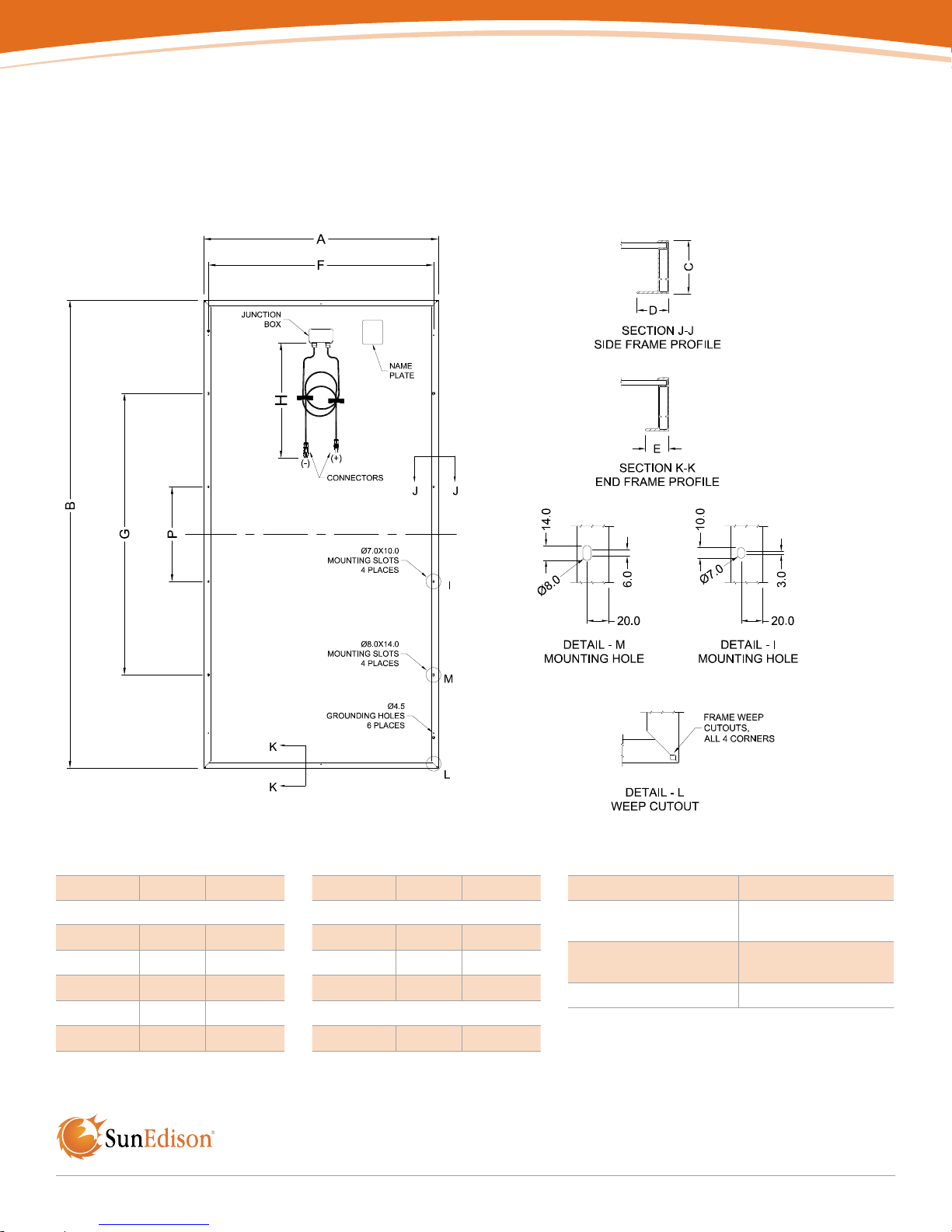
7.0 Appendix
7.1 Module Details
PHYSICAL PARAMETERS
Dimension mm inch
Module Dimensions
A 990 39.0
B 1,976 77.8
C 50 2.0
D 30 1.2
E 22 0.9
Dimension mm inch
Mounting Hole Spacing
F 950 37.4
G 1,188 46.8
P 400 15.7
Cable Length
H 1,300 51.2
© 2015 SunEdison 14
Module Weight 22 kg
Frame Material
Tempered ARC Glass
Thickness
Connector Types Amphenol H4 (-39)
Anodized aluminum
alloy
3.2 mm

7.2 Center Clamp Module Installation Illustrations
7.3 Module Clamp Drawings
Bolt Stack Details Center Mount Option
PHYSICAL PARAMETERS
Dimension mm inch
Module Clamp Dimensions
A 6.35 0.25
B 38 1.5
Minimum Clamp Dimensions
C 50 1.97
D 15 0.59
© 2015 SunEdison 15

SunEdison Delivers Solar
Solutions Around the World
Australia
Brazil
Bulgaria
Canada
Chile
China
France
Germany
Greece
India
Indonesia
Israel
Italy
Japan
Jordan
Malaysia
Mexico
South Africa
South Korea
Spain
Taiwan
Turkey
U.A.E
United Kingdom
U.S.A.
www.sunedison.com
600 Clipper Drive Belmont, CA 94002
Phone: 866-786-3347 or 650-453-5600 Fax: 443-909-7150
©2015 SunEdison Products Singapore Pte. Ltd.; A SunEdison Company. All rights reserved. SunEdison and the SunEdison logo are registered trademarks or trademarks of SunEdison
Products Singapore Pte. Ltd. and/or its affiliates in the United States and certain other countries. All other trademarks mentioned in this document are the property of their respective
owners.
LWI-19389 TF_F_R72_GD_50mm_v4 07.2015
 Loading...