

Page 1
1
November, 2014 Rev.C
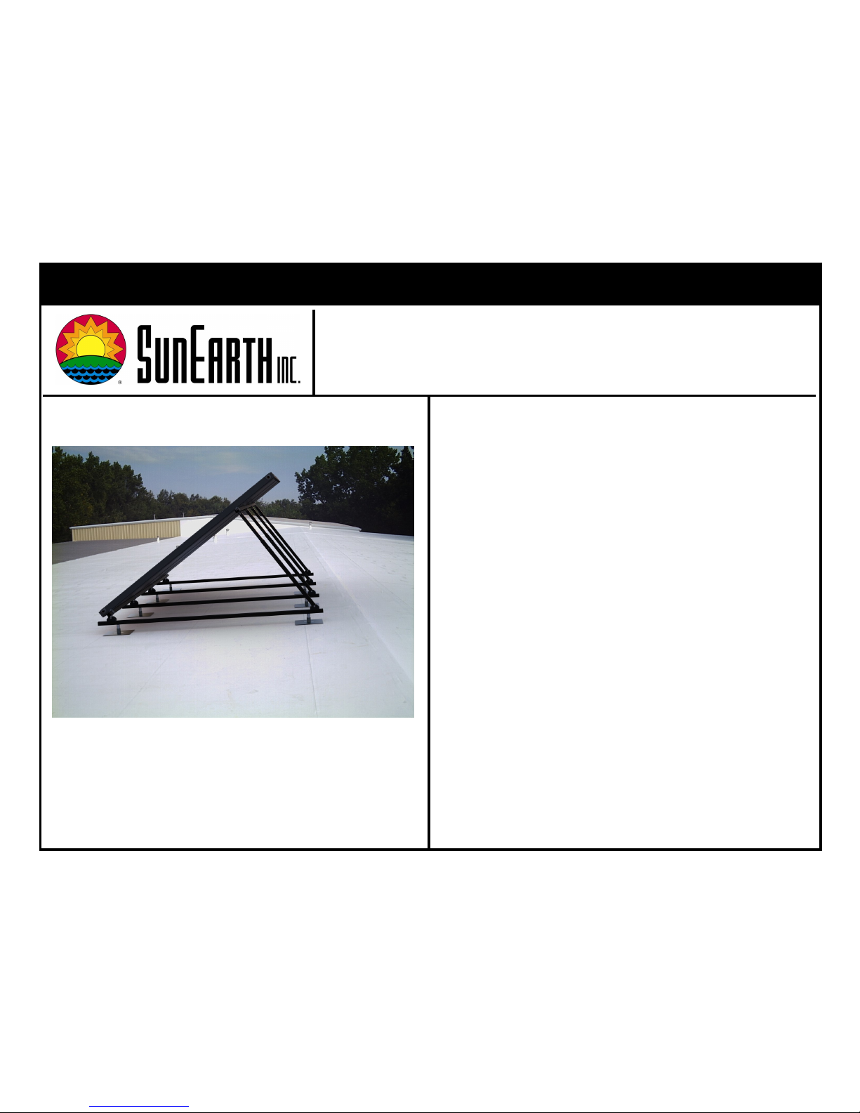
RexRack
SunEarth RexRack Installaon Manual
Thank you for purchasing SunEarth’s RexRack System. The
use of all stainless steel hardware and 6063-T6 structural alu-
minum make SunEarth’s RexRack a simple, strong and dura-
ble solution for your racking needs. It accommodates tilt angles from 20° to 60° from horizontal and is compatible with all
SunEarth solar collectors.
The RexRack components consist of 6063-T6 anodized aluminum mounting feet, support strut, rear leg as well as collectors clips and stainless steel fasteners that can withstand the
harshest weather conditions. The components have factory
machined holes to expedite field installation.
SunEarth’s RexRack has been designed to allow installation on
all roof types. Always maintain a tilt angle greater than 10°
from horizontal.
RexRack should not be used in areas that experience positive
panel loading (snow) greater than 60 psf or negative panel
loading (wind) greater than 60 psf. If expected loading exceeds these values please contact SunEarth for other mounting options.
The use of mounting systems that do not conform to the ma-
terials and methods detailed in this or any of SunEarth’s other
published installation manuals, guidelines, and technical bulletins is not recommended and may void your collector warranty.
SunEarth RexRack
Low Slope Roof Installation
Page 2
2
November, 2014 Rev.C
RexRack — Location
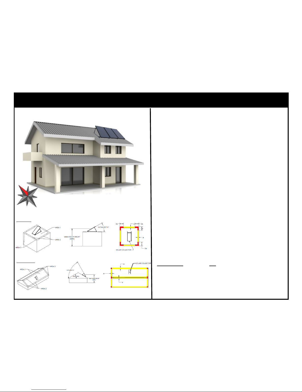
The optimal siting of the solar collector is facing true south. If
this is not possible the annual performance will suffer very little
if the collector is oriented no more than 45° east or west of
true south.
The solar collector should be placed on the roof in an area and
orientation that minimizes wind and snow loading. Wind loads
are highest near the edges and ridge of the roof. It is not advisable to install solar collectors in locations 2 (yellow) and 3
(red) on the plan view shown on the left.
Example: If the installation site has a roof that is 35 feet wide,
60 feet long and has a mean roof height of 30 feet.
10% of “LHD” = 0.10 X 35 = 3.5
4% of “LHD” = 0.04 X 35 = 1.4
40% of “MRH” = 0.40 X 30 = 12
a = 3.5 feet since 1.4<3<3.5<12
Therefore collectors should be installed at least 3.5 feet away
from any roof peak or edge.
S
Flat Roof 20° ≤ Collector Tilt ≤ 60°
Gable Roof 20° ≤ Collector Tilt ≤ 60°
Note: If either the roof length or width is less than 30 feet
then “a” is equal to 3 feet. Otherwise dimension “a” is 10% of
the least horizontal dimension ”LHD” or 40% of the mean roof
height “MRH” whichever is smaller, but not less than either 4%
of the least horizontal dimension of the building or 3 feet as
stated in Minimum Design Loads for Buildings and Other Structures, American Society of Civil Engineers (ASCE) 7-05.
Page 3
3
November, 2014 Rev.C
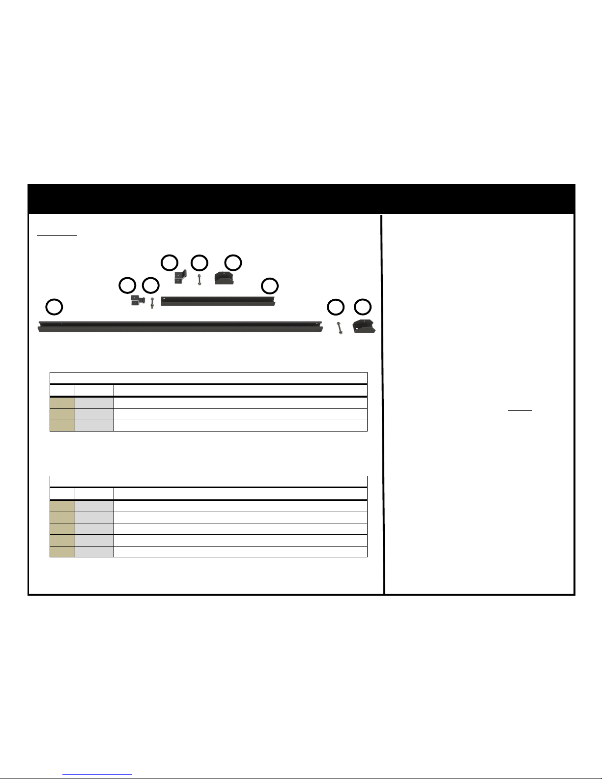
RexRack — Tilt Kit Components
Includes
Verify that all components shown to the
left have been received before proceeding
with installation.
Note: Mounting Feet should never be attached directly to the roof surface without
best practice flashing methods. Roof attachment products such as standoffs,
hanger bolts, etc. should be implemented
to allow proper flashing.
1
2
3
4
5
6
2
2
3
Front Foot Assembly Part # MTG-FF-BA
Qty. Descripon
1
1 ea. Front Hinge Bracket (Black Anodized Shown)
2 1 ea. Fastener Assembly
3 1 ea. Mounng Foot (Black Anodized Shown)
Table 1
Rear Telescoping Leg Assembly Part # MTG-RTL-2441/3865/5897/86122
Qty. Descripon
2
2ea. Fastener Assembly
3 1 ea. Mounng Foot (Black Anodized Shown)
4 1 ea. Rear Hinge Bracket (Black Anodized Shown)
5 1 ea. Rear Leg Slider (Black Anodized Shown)
6 1 ea. Rear Leg (Black Anodized Shown)
Table 2
Page 4
4
November, 2014 Rev.C
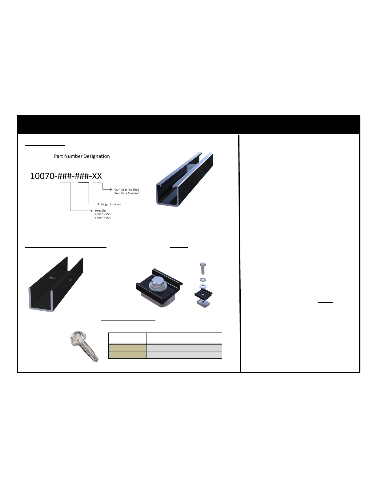
The Collector Mounting Assembly (C-SSN)
attaches the collector to the RexRack, 4
required per collector.
RexRack — Additional Components
Support Strut
Example: 10070-158-324-BA = 1-5/8” Support Strut 27’ in Length and Black Anodized
Support Strut Splice*Optional C-SSN
The Support Strut Splice (MTG-SPLICE-8)
is used to extend the Support Strut for
lengths greater than 27 feet or as required.
The Support Strut (10070-###-###-XX)
is used to support the collectors in addition allowing for attachment of the Front
Foot Assembly (MTG-FF-XX) and Rear Tel-
escoping leg Assembly (MTG-RTL2441/3865/5897/86122).
4 Required per Collector
The Self Drilling Screws (14BW12X3/4)
are used to both fix the length of the rear
telescoping legs and secure the hinges to
the Support Strut. See Table 3
Self Drilling Screw
SunEarth Part # Required Number of Screws
MTG-FF-XX
3
MTG-RTL-XXXX 5
The Support Strut Splice (MTG-SPLICE-8)
is used to extend the Support Strut for
lengths greater than 27 feet or as required.
Table 3
Note: Mounting Feet should never be attached directly to the roof surface without
best practice flashing methods. Roof attachment products such as standoffs,
hanger bolts, etc. should be implemented
to allow proper flashing.
Page 5
5
November, 2014 Rev.C
RexRack — Assembly Details
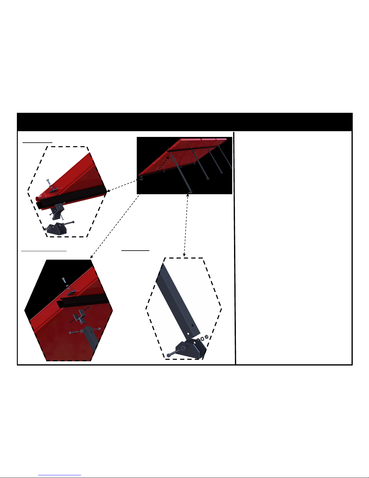
Rear Foot
The Front Foot assembly consists of the
Front Hinge Bracket nesting in the Front
Foot and attachment with one (1) fastener
assembly per front foot. The low support
strut is then nested in the Front Hinge
Bracket and secured with three (3) selfdrilling screws as shown.
Leg Attachment
Front Foot
The Rear Foot sub-assembly consists of
the Rear Telescoping Leg being nested in
the Rear Foot and attachment with one
(1) fastener assembly per foot.
The Leg attachment consists of the Rear
Hinge bracket nesting in the Rear Telescoping Leg and attachment with one (1)
fastener assembly per leg. The upper support strut is then nested in the rear Hinge
bracket and secured with two (2) selfdrilling screws.
Page 6
6
November, 2014 Rev.C
RexRack — Layout
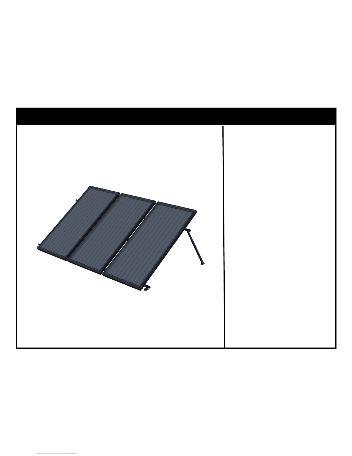
Portrait Configuration Only
SunEarth’s RexRack is not an appro-
priate mounting solution for locations that experience positive panel
loading (snow) greater than 60 psf
or negative panel loading (wind)
greater than 60 psf. If expected
loading exceeds these values please
contact SunEarth for other mounting
options.
SunEarth’s RexRack layout is out-
lined for the different RexRack models dependent on collector and desired tilt angle. Please reference appropriate sheet for your application.
Page 7
7
November, 2014 Rev.C
RexRack — Support Strut Length, Copper Coupling
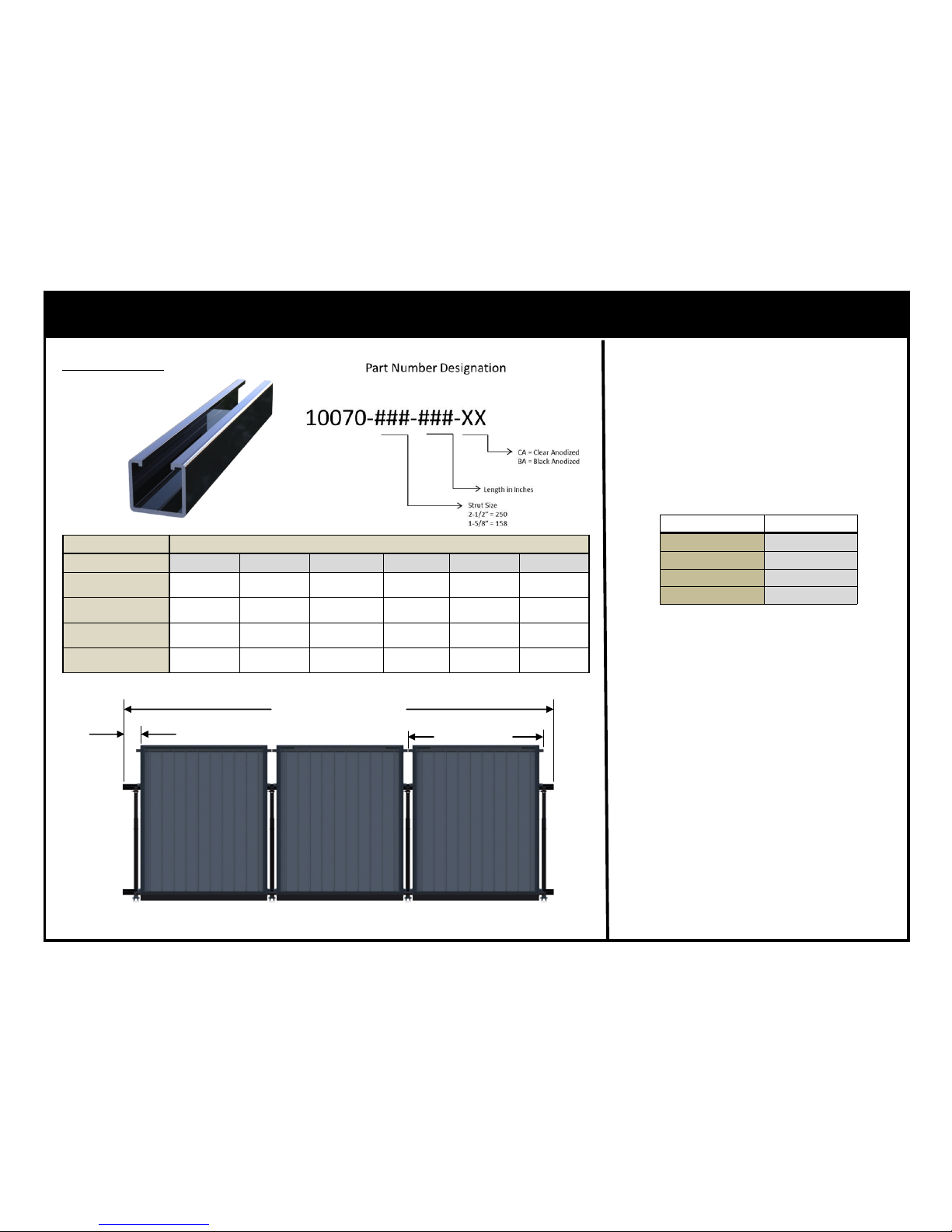
Calculate the required length of the
Support Struts (10070-###-###XX). This will be the widest feature
of the row. The length of the support
strut follows the formula outlined
below.
Support Strut
SunEarth Collector # Header Length (h)
EC/EP/SB-40-XX
51.375”
EC/EP/SB-32-XX 51.375”
EC/EP/SB-24-XX 39.75”
EC/EP-21-XX 43.375”
Support Strut Length =
(# of Collectors) * (h + 0.125”) - (0.875”)
Example: Given (6) SunEarth EP40 collectors. Required length of each
Support Strut = (6*(51.375+.125.875= 309.875”
In this example two options are available.
1. A single 27’ piece of Support Strut
(10070-158-324-BA).
2. Two pieces of 158” Support Strut
(10070-158-158-BA) with a Support Strut Splice (MTG-SPLICE-8)
to connect the 2 sections.
1.25” BEYOND COLLECTOR
LENGTH OF SUPPORT STRUTS
HEADER LENGTH (h)
Table 4
Quanty
SunEarth Collector # 1 2 3 4 5 6
XX-40-#.##
10070-158-052-
XX
10070-158-104-
XX
10070-158-158-
XX
10070-158-244-
XX
10070-158-288-
XX
10070-158-324-
XX
XX-32-#.##
10070-158-052-
XX
10070-158-104-
XX
10070-158-158-
XX
10070-158-244-
XX
10070-158-288-
XX
10070-158-324-
XX
XX-24-#.##
10070-158-052-
XX
10070-158-082-
XX
10070-158-120-
XX
10070-158-158-
XX
10070-158-204-
XX
10070-158-244-
XX
XX-21-#.##
10070-158-052-
XX
10070-158-104-
XX
10070-158-158-
XX
10070-158-204-
XX
10070-158-244-
XX
10070-158-288-
XX
SunEarth Collector # Header Length (h)
XX-40-#.##
51.375”
XX-32-#.## 51.375”
XX-24-#.## 39.375”
XX-21-#.## 43.375”
Page 8
8
November, 2014 Rev.C
RexRack — Support Strut Length, Union
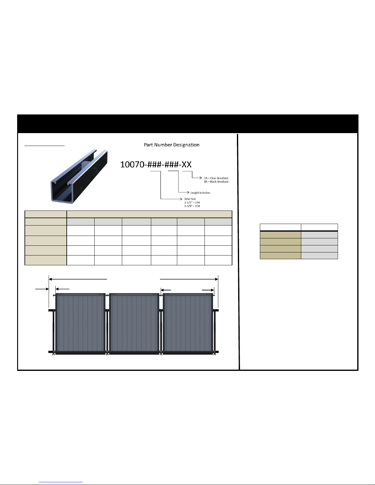
Calculate the required length of the
Support Struts (10070-###-###XX). This will be the widest feature
of the row. The length of the support
strut follows the formula outlined
below.
Support Strut
(UNION-SET-1) Support Strut Length =
(# of Collectors) * (h + 0.25”) + (2.5”)
Example: Given (6) SunEarth EP40 collectors. Required length of each
Support Strut = (6*(51.375+.25)
+2.5) = 312.25”
In this example two options are available.
1. A single 27’ piece of Support Strut
(10070-158-324-BA).
2. Two pieces of 158” Support Strut
(10070-158-158-BA) with a Support Strut Splice (MTG-SPLICE-8)
to connect the 2 sections.
1.25” BEYOND COLLECTOR
LENGTH OF SUPPORT STRUTS
HEADER LENGTH (h)
Table 4
(UNION-SET-1.5) Support Strut Length =
(# of Collectors) * (h + 0.375”) + (2.5”)
Quanty
SunEarth Collector # 1 2 3 4 5 6
EC/EP/SB-40-XX
10070-158-052-
XX
10070-158-104-
XX
10070-158-158-
XX
10070-158-244-
XX
10070-158-288-
XX
10070-158-324-
XX
EC/EP/SB-32-XX
10070-158-052-
XX
10070-158-104-
XX
10070-158-158-
XX
10070-158-244-
XX
10070-158-288-
XX
10070-158-324-
XX
EC/EP/SB-24-XX
10070-158-052-
XX
10070-158-082-
XX
10070-158-120-
XX
10070-158-204-
XX
10070-158-204-
XX
10070-158-244-
XX
EC/EP/SB-21-XX
10070-158-052-
XX
10070-158-104-
XX
10070-158-158-
XX
10070-158-204-
XX
10070-158-244-
XX
10070-158-288-
XX
SunEarth Collector # Header Length (h)
EC/EP/SB-40-XX
51.375”
EC/EP/SB-32-XX 51.375”
EC/EP/SB-24-XX 39.75”
EC/EP-21-XX 43.375”
Page 9
9
November, 2014 Rev.C
RexRack — Splice Information
7
7
8
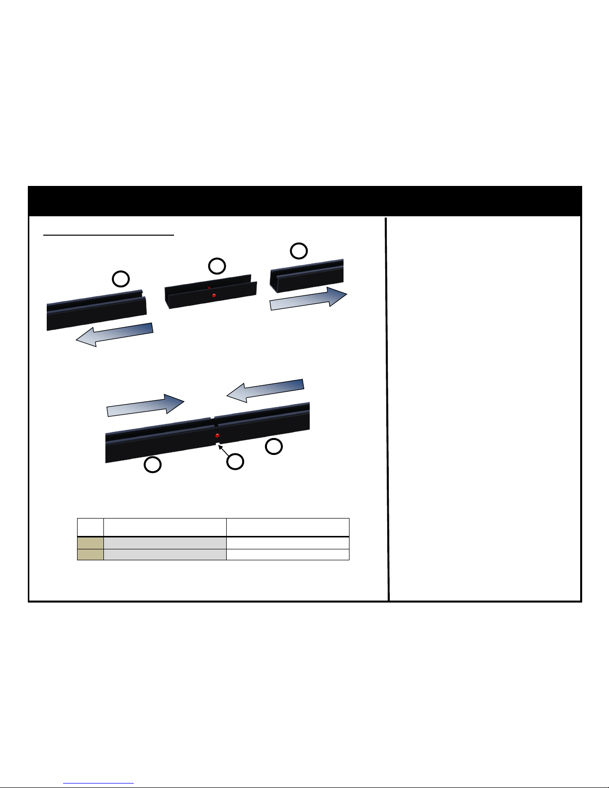
Support Strut is available in lengths
up to 27’. If the calculated Support
Strut length is longer than 27’ then
a Support Strut Splice must be implemented.
Support Strut Splice*Optional
For 1-5/8” Support Strut the Sup-
port Strut Splice MTG-SPLICE-8 is
used by sliding the splice into one
Support Strut until touching the riveted stop, shown in RED for illustrative purposes. Then the other Support Strut is slid onto the splice until
it touches the rivet stop.
The Support Strut Splice MTGSPLICE-8 has been designed so that
no additional fasteners are required
while continuing to allow for thermal
expansion and contraction of the
Support Strut.
7
7
8
SunEarth Part # Descripon
7
10070-###-###-XX Support Strut
8 MTG-SPLICE-8 Support Strut Splice
Table 5
Page 10
10
November, 2014 Rev.C
RexRack — EC/EP/SB-40 Layout
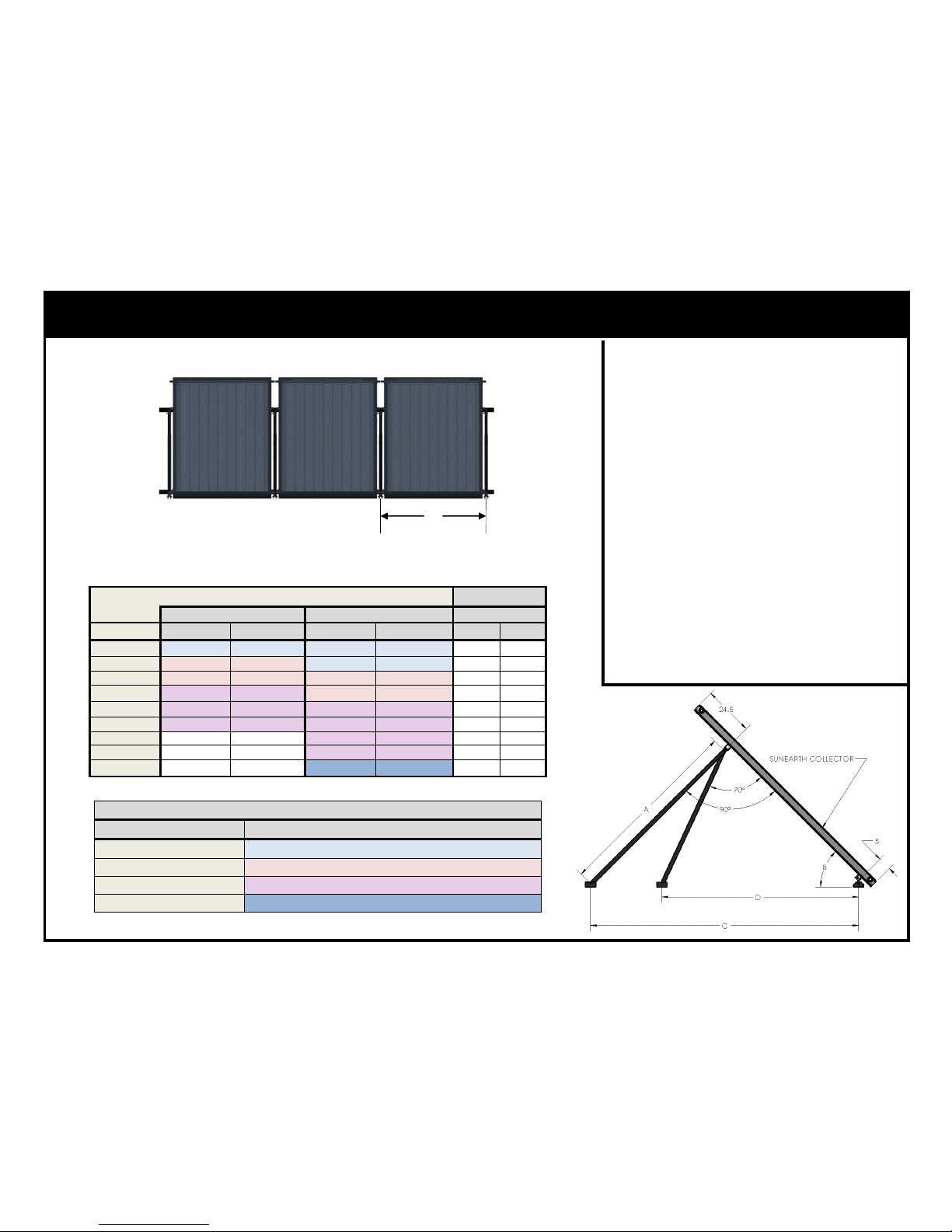
RexRack Layout Dimensions
Table 6 provides detail on the proper
placement of the RexRack feet for
SunEarth Collector(s).
If the rafter spacing is not 16” or 24” on
center, position the RexRack feet such
that the collector “overhang” is less than
12”. The maximum allowable Leg Spacing (E) is 60” on center for installations
utilizing 1-5/8” Solar Strut.
Raer Spacing EC/EP/SB/TRB/IS/IC—40
Leg 90° from Collector Leg 70° from Collector Leg Spacing (E)
Tilt Angle (B) Leg Length (A) Foot Spacing (C) Leg Length (A) Foot Spacing (D) 16" 24"
20 33.4 97.6 31.4 86.2 48 48
25 42.8 101.2 38.9 86.5 48 48
30 52.9 105.9 46.6 87.5 48 48
35 64.2 111.9 54.5 89.2 48 48
40 76.9 119.7 62.7 91.7 48 48
45 91.7 129.7 71.5 95.1 48 48
50 - - 81.1 99.5 48 48
55 - - 91.7 105.2 48 48
60 - - 103.7 112.5 48 48
SunEarth Collector Part # EC/EP/SB-40
Note: All tilt angles are taken for the
racking only, relative to horizontal. Roof
pitch must be added or subtracted as
appropriate to calculate the collector tilt.
A general rule of thumb is collector tilt
should be equal to local latitude plus
10°.
E
Table 6
Rear Telescoping Leg Assembly Part # MTG-RTL-2441/3865/5897/86122
Adjustment Range
MTG-RTL-2441-XX
24” to 41”
MTG-RTL-3865-XX 38” to 65”
MTG-RTL-5897-XX 58” to 97”
MTG-RTL-86122-XX 86” to 122”
Table 7
Page 11
11
November, 2014 Rev.C
RexRack — EC/EP/SB-32 Layout
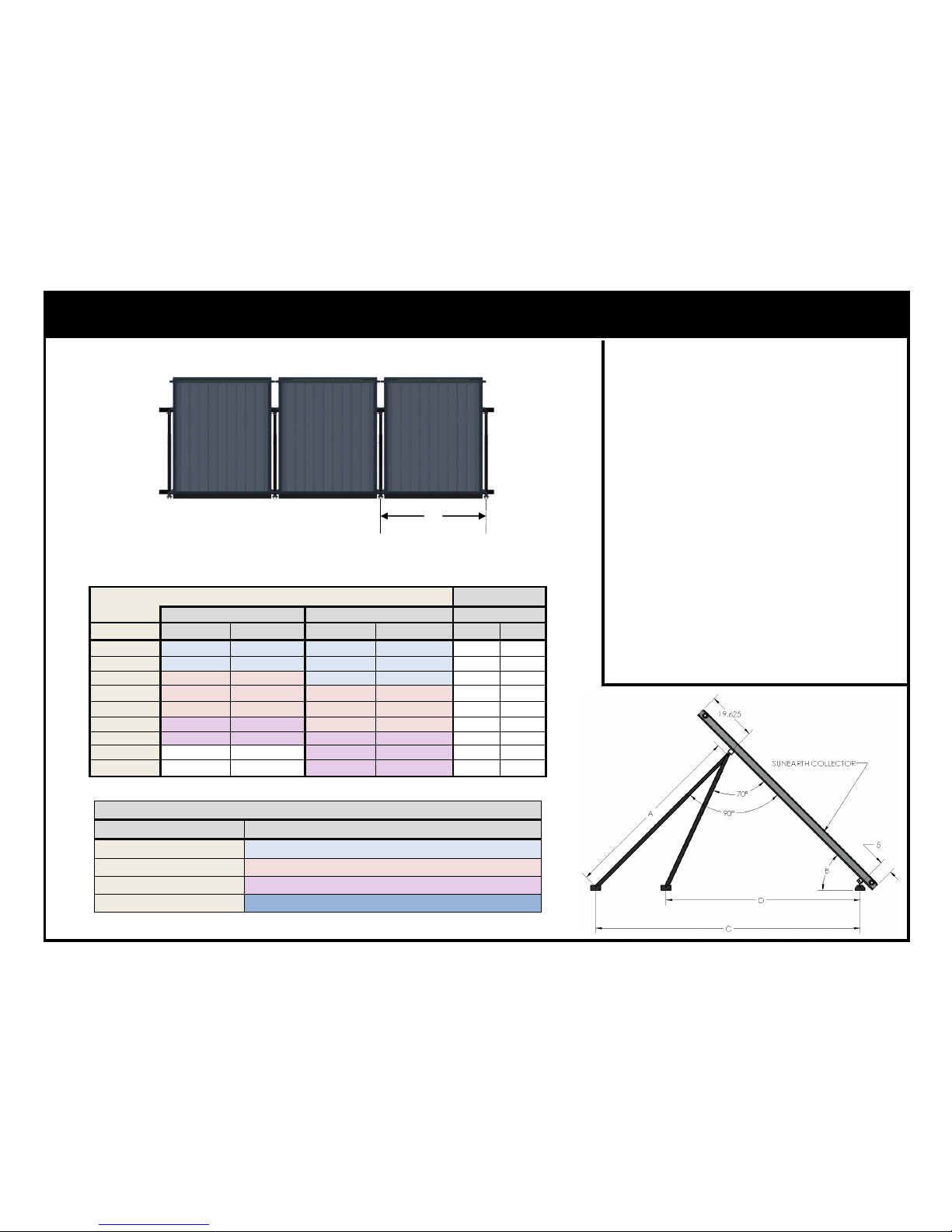
RexRack Layout Dimensions
Table 8 provides detail on the proper
placement of the RexRack feet for
SunEarth Collector(s).
Raer Spacing
Leg 90° from Collector Leg Spacing (E) Leg 70° from Collector
Tilt Angle (B) Leg Length (A) Foot Spacing (C) Leg Length (A) Foot Spacing (D) 16" 24"
20 26.4 77.2 24.8 68.1 48 48
25 33.8 80.0 30.8 68.4 48 48
30 41.9 83.7 36.8 69.2 48 48
35 50.8 88.5 43.1 70.5 48 48
40 60.8 94.6 49.6 72.5 48 48
45 72.5 102.5 56.6 75.2 48 48
50 86.4 112.8 64.1 78.7 48 48
55 - - 72.5 83.2 48 48
60 - - 82.0 88.9 48 48
SunEarth Collector Part # EC/EP/SB-32
E
Table 8
Rear Telescoping Leg Assembly Part # MTG-RTL-2441/3865/5897/86122
Adjustment Range
MTG-RTL-2441-XX
24” to 41”
MTG-RTL-3865-XX 38” to 65”
MTG-RTL-5897-XX 58” to 97”
MTG-RTL-86122-XX 86” to 122”
Table 7
Note: All tilt angles are taken for the
racking only, relative to horizontal. Roof
pitch must be added or subtracted as
appropriate to calculate the collector tilt.
A general rule of thumb is collector tilt
should be equal to local latitude plus
10°.
If the rafter spacing is not 16” or 24” on
center, position the RexRack feet such
that the collector “overhang” is less than
12”. The maximum allowable Leg Spacing (E) is 60” on center for installations
utilizing 1-5/8” Solar Strut.
Page 12
12
November, 2014 Rev.C
RexRack — EC/EP/SB-24 Layout
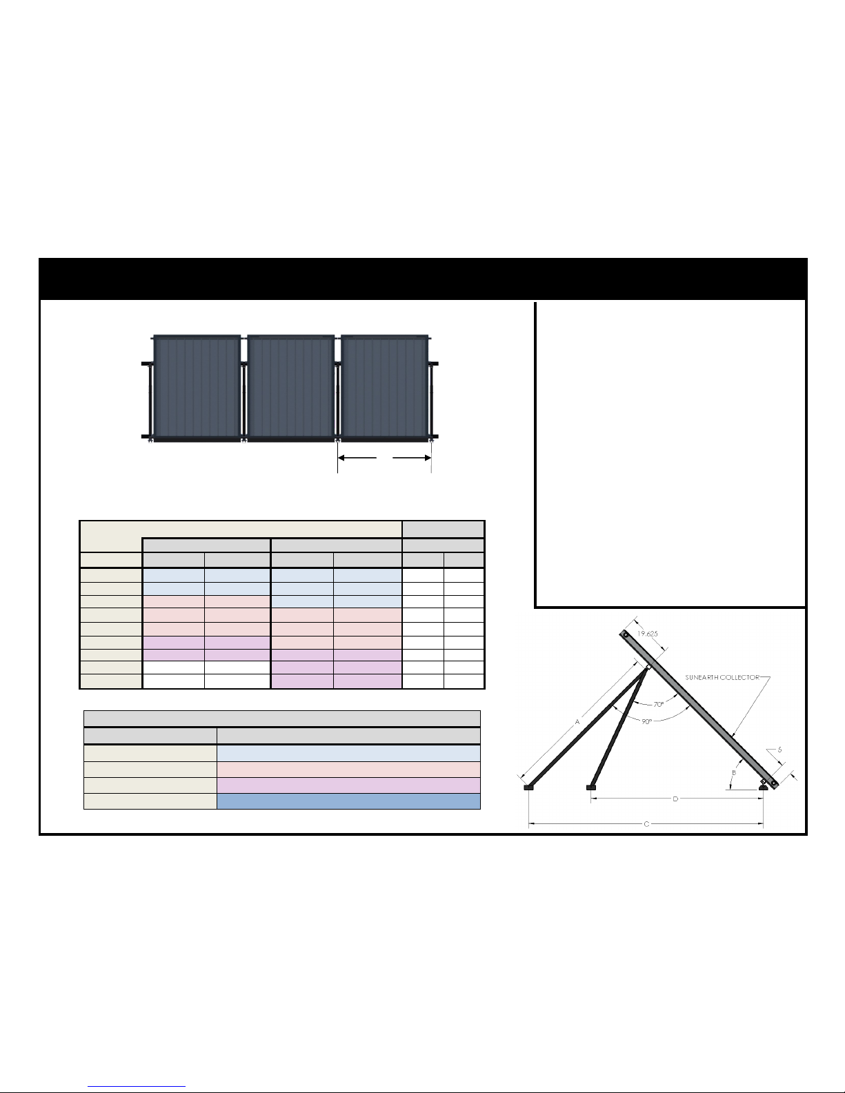
RexRack Layout Dimensions
Table 9 provides detail on the proper
placement of the RexRack feet for
SunEarth Collector(s).
Raer Spacing
Leg 90° from Collector Leg Spacing (E) Leg 70° from Collector
Tilt Angle (B) Leg Length (A) Foot Spacing (C) Leg Length (A) Foot Spacing (D) 16" 24"
20 26.4 77.2 24.8 68.1 48 48
25 33.8 80.0 30.8 68.4 48 48
30 41.9 83.7 36.8 69.2 48 48
35 50.8 88.5 43.1 70.5 48 48
40 60.8 94.6 49.6 72.5 48 48
45 72.5 102.5 56.6 75.2 48 48
50 86.4 112.8 64.1 78.7 48 48
55 - - 72.5 83.2 48 48
60 - - 82.0 88.9 48 48
SunEarth Collector Part # EC/EP/SB-24
E
Table 9
Rear Telescoping Leg Assembly Part # MTG-RTL-2441/3865/5897/86122
Adjustment Range
MTG-RTL-2441-XX
24” to 41”
MTG-RTL-3865-XX 38” to 65”
MTG-RTL-5897-XX 58” to 97”
MTG-RTL-86122-XX 86” to 122”
Table 7
Note: All tilt angles are taken for the
racking only, relative to horizontal. Roof
pitch must be added or subtracted as
appropriate to calculate the collector tilt.
A general rule of thumb is collector tilt
should be equal to local latitude plus
10°.
If the rafter spacing is not 16” or 24” on
center, position the RexRack feet such
that the collector “overhang” is less than
12”. The maximum allowable Leg Spacing (E) is 60” on center for installations
utilizing 1-5/8” Solar Strut.
Page 13
13
November, 2014 Rev.C
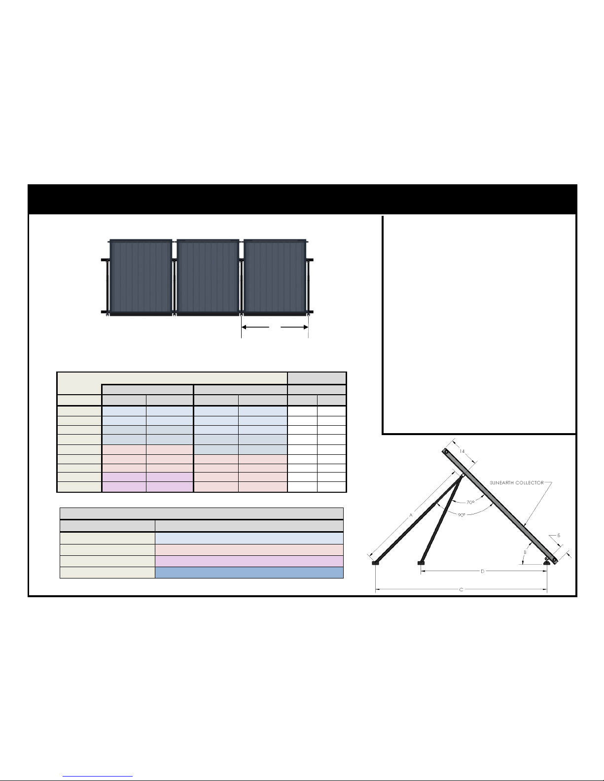
RexRack — EC/EP/SB-21 Layout
RexRack Layout Dimensions
Table 10 provides detail on the proper
placement of the RexRack feet for
SunEarth Collector(s).
Raer Spacing
Leg 90° from Collector Leg Spacing (E) Leg 70° from Collector
Tilt Angle (B) Leg Length (A) Foot Spacing (C) Leg Length (A) Foot Spacing (D) 16" 24"
20 18.3 53.4 17.2 47.2 48 48
25 23.4 55.4 21.3 47.4 48 48
30 29.0 58.0 25.5 47.9 48 48
35 35.2 61.3 29.8 48.8 48 48
40 42.1 65.5 34.3 50.2 48 48
45 50.2 71.0 39.2 52.0 48 48
50 59.8 78.1 44.4 54.5 48 48
55 71.7 87.5 50.2 57.6 48 48
60 86.9 100.4 56.8 61.6 48 48
SunEarth Collector Part # EC/EP/SB-21
E
Table 10
Rear Telescoping Leg Assembly Part # MTG-RTL-2441/3865/5897/86122
Adjustment Range
MTG-RTL-2441-XX
24” to 41”
MTG-RTL-3865-XX 38” to 65”
MTG-RTL-5897-XX 58” to 97”
MTG-RTL-86122-XX 86” to 122”
Table 7
Note: All tilt angles are taken for the
racking only, relative to horizontal. Roof
pitch must be added or subtracted as
appropriate to calculate the collector tilt.
A general rule of thumb is collector tilt
should be equal to local latitude plus
10°.
If the rafter spacing is not 16” or 24” on
center, position the RexRack feet such
that the collector “overhang” is less than
12”. The maximum allowable Leg Spacing (E) is 60” on center for installations
utilizing 1-5/8” Solar Strut.
Page 14
14
November, 2014 Rev.C
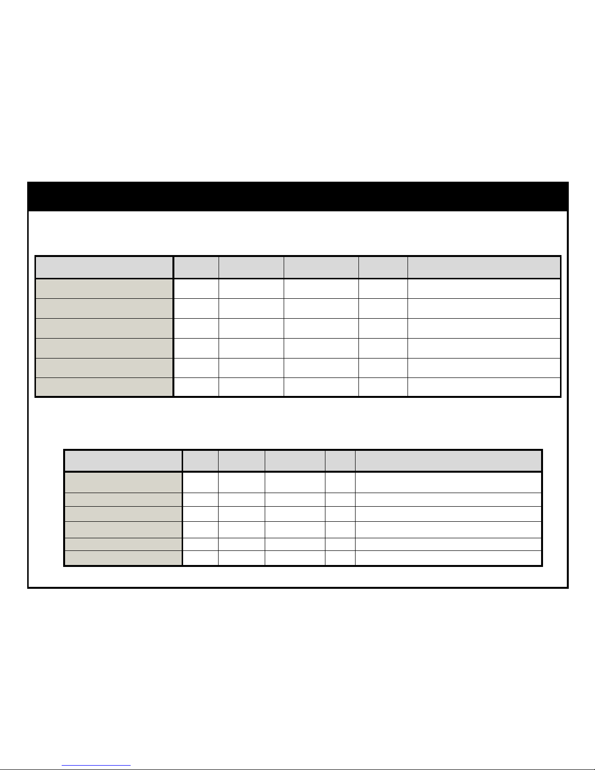
RexRack — Order Sheet
Item Length # of Parts PN Page Notes:
Collector Mounting Assembly N/A C-SSN 4
Support Strut 10070- - - 7
Support Strut Splice* N/A MTG-Splice-8 8
Rear Telescoping Leg Assembly MTG-RTL- - 9-12
Front Foot Assembly N/A MTG-FF- 9-12
Self Drilling Screws N/A 14BW12X3/4 4
RexRack Parts list
Example: Given (6) SunEarth EP-40 collectors to be installed at a 45° lt.
Item Length # of Parts PN Page Notes:
Collector Mounting Assembly N/A 24 C-SSN 4 4 Per Collector. 4*6=24
Support Strut 158”x2 4 10070-158-158-BA 7 311.5” per Support Strut. 2 Support Struts Required
Support Strut Splice* N/A 2 MTG-Splice-8 8 Splices Required Since Each Support Strut Made of 2 Pieces
Rear Telescoping Leg Assembly 71.5” 7 MTG-RTL-5897-BA 9 Assumed Spacing of 48” OC
Front Foot Assembly N/A 7 MTG-FF–BA 9 Quantity is equal to Rear Telescoping Leg
Self Drilling Screws N/A 56 14BW12X3/4 4 3 per Front Foot Assembly, 5 Per Rear Telescoping Leg
Sample RexRack Parts list
Page 15
15
November, 2014 Rev.C
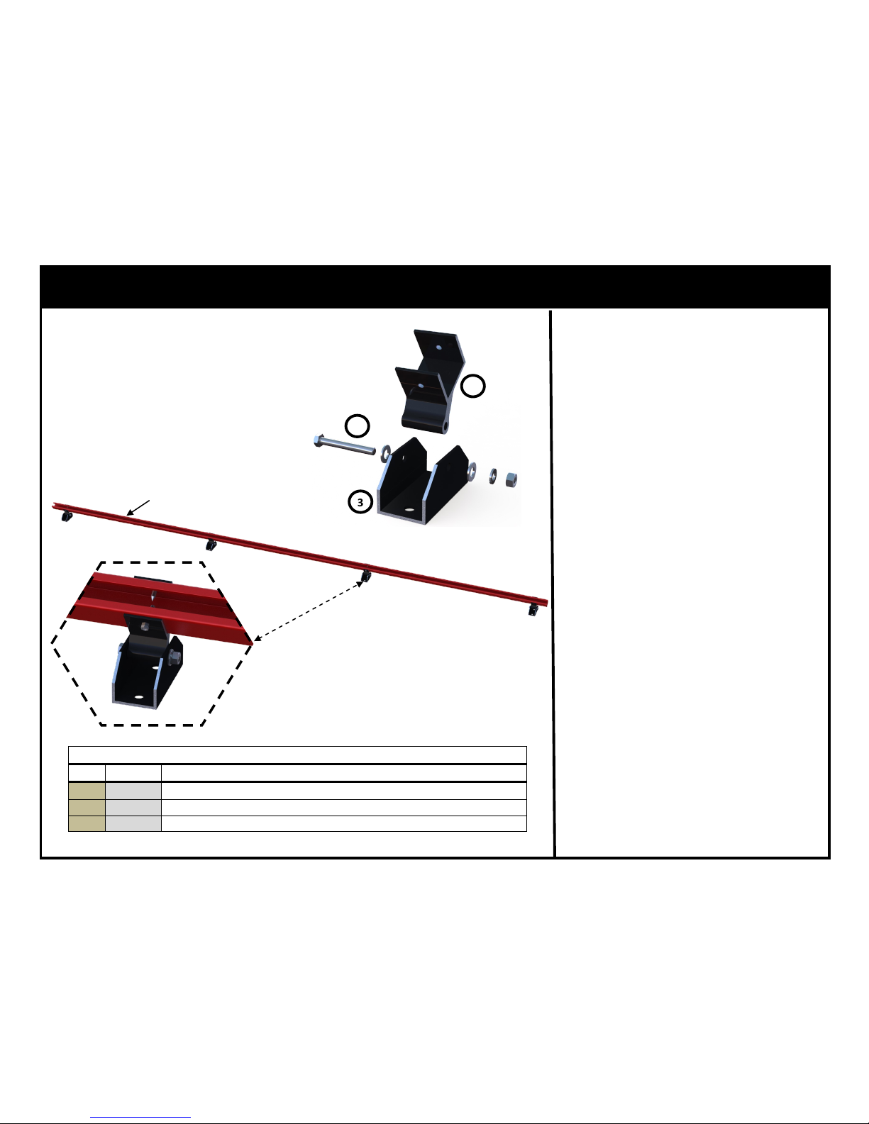
RexRack — Front Mounting Foot Installation
1. Mark the location of the Front
Mounting Feet on the main mounting surface as outlined on Tables 6,
8, 9 & 10.
2. Securely fasten the Front Mounting
Feet to the main mounting surface
using acceptable fastening methods
for the mounting surface as well as
local codes and conditions. *Check
that all Front Mounting Feet are
level and co-planar in respect to
each other by adding shims as
needed.
3. Insert the Front Hinge Bracket into
the Front Mounting Foot with the
opening of the channel facing away
from the mounting surface. Insert
Fastener Assembly thru Front
Mounting Foot and Front Hinge
Bracket. As shown in Figure 1.
4. Insert Lower Support Strut, shown
in RED for illustrative purposes, into
the Front Hinge Bracket and secure
with three (3) Self Drilling Screws
per Mounting Foot as shown in Fig-
ure 2.
Note: Always follow all local building codes,
ordinances and regulations when creating roof
penetrations as well as standard roofing trade
practices.
Front Foot Assembly Part # MTG-FF-BA
Qty. Descripon
1
1 ea. Front Hinge Bracket (Black Anodized Shown)
2 1 ea. Fastener Assembly
3 1 ea. Mounng Foot (Black Anodized Shown)
Table 1
1
2
3
Figure 1
Figure 2
Lower Support Strut
Page 16
16
November, 2014 Rev.C
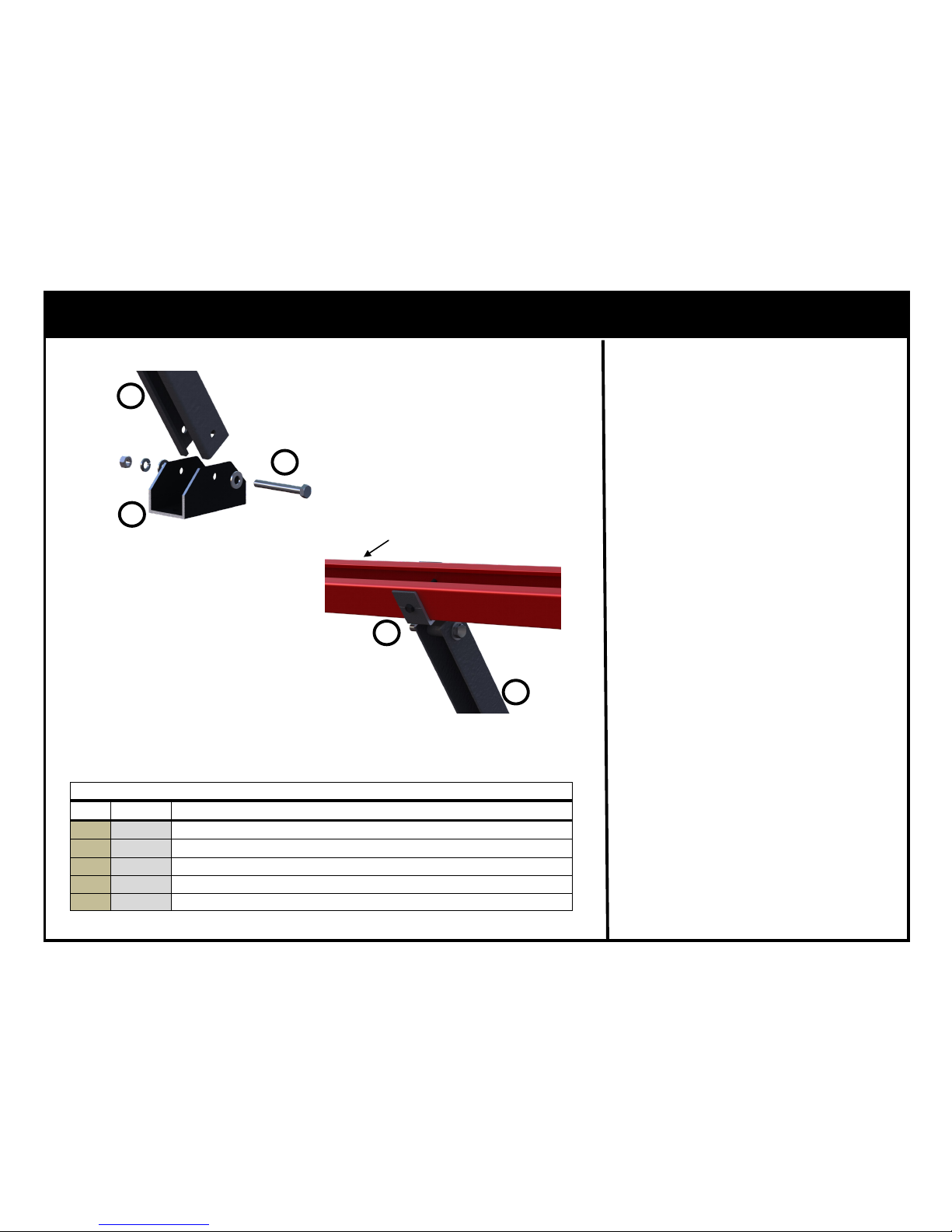
RexRack — Rear Telescoping Leg Assembly Installation
1. Mark the location of the Rear
Mounting Feet on the main mounting surface as outlined on Tables 6,
8, 9 & 10.
2. Securely fasten the Rear Mounting
Feet to the main mounting surface
using acceptable fastening methods
for the mounting surface as well as
local codes and conditions.
3. Position the Rear Telescoping Leg
Assembly on the Rear Mounting
Foot with the opening of the channel facing the front foot. Insert Fastener Assembly thru the Rear
Mounting Foot and the Rear Telescoping Leg Assembly. As shown in
Figure 3.
4. Insert Upper Support Strut, shown
in RED, into the Rear Hinge Bracket
and secure with two (2) Self Drilling
Screws per Mounting Foot as shown
in Figure 4.
Figure 4
Rear Telescoping Leg Assembly Part # MTG-RTL-2441/3865/5897/86122
Qty. Descripon
2
2ea. Fastener Assembly
3 1 ea. Mounng Foot (Black Anodized Shown)
4 1 ea. Rear Hinge Bracket (Black Anodized Shown)
5 1 ea. Rear Leg Slider (Black Anodized Shown)
6 1 ea. Rear Leg (Black Anodized Shown)
Table 2
Figure 3
2
3
5
4
5
Upper Support Strut
Note: Always follow all local building codes,
ordinances and regulations when creating roof
penetrations as well as standard roofing trade
practices.
Page 17
17
November, 2014 Rev.C
RexRack — Rear Telescoping Leg Assembly Installation
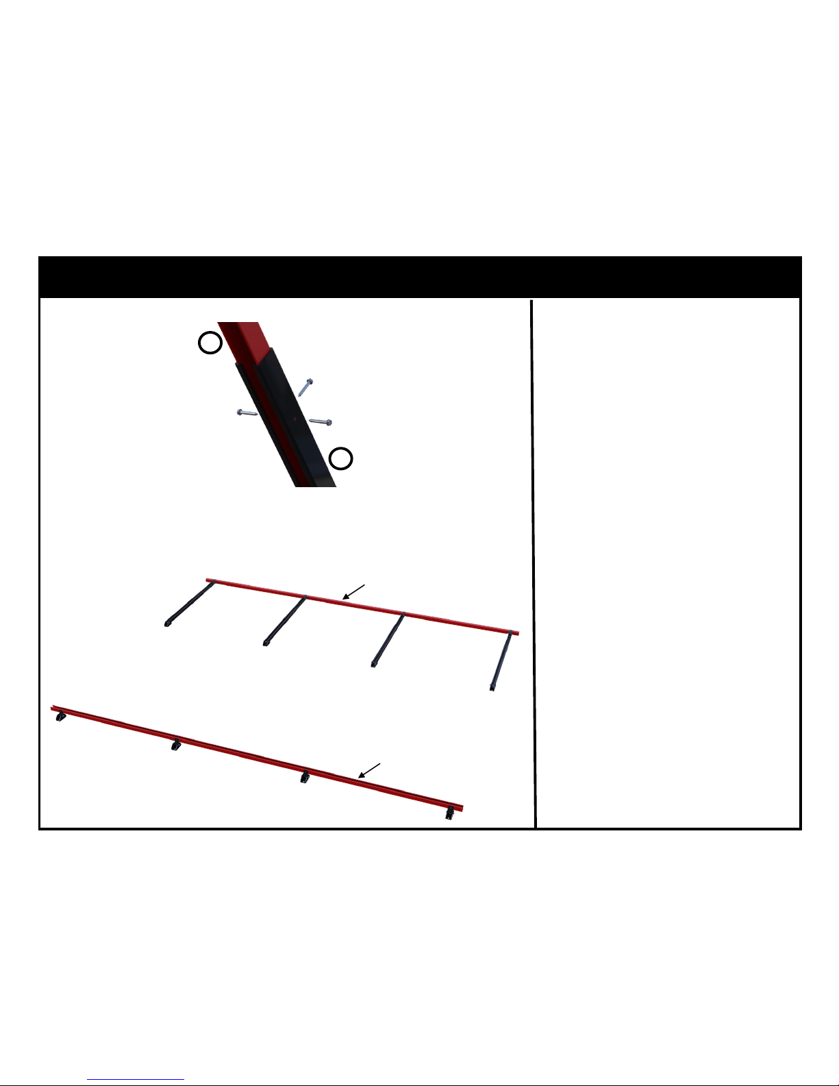
5. Set the Rear Telescoping Leg Assembly length as outlined in Ta-
bles 6, 8, 9 & 10.
6. Secure every Rear Leg Slider,
shown in RED, to every Rear Leg
with three (3) Self Drilling
Screws as shown in Figure 5.
7. Swing Rear Telescoping Leg Assemblies with Upper Support
backwards and lay flat on
mounting surface as shown in
Figure 6.
Note: Always follow all local building
codes, ordinances and regulations
when creating roof penetrations as
well as standard roofing trade practices.
5
6
Figure 5
Figure 6
Upper Support Strut
Lower Support Strut
Page 18
18
November, 2014 Rev.C
RexRack — First Collector Placement
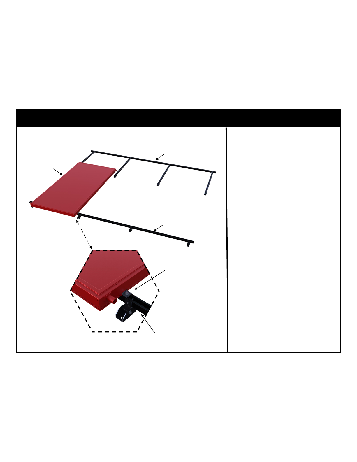
1. Place the first Collector face up
on the Lower Support Strut with
the lower end of the Collector
overhung 5” beyond the Lower
Support Strut. As shown in Figure 5.
2. Position Collector inboard with
the Collectors long end a mini-
mum of 1.5” from the edge of
the Lower Support Strut.
3. Install two (2) C-SSN Collector
Mounting Assemblies on the Lower Support Strut and torque to
19 ft*lbs (26 N*m).
Figure 5
Collector
Lower Support Strut
Upper Support Strut
Collector Mounng Assembly
Lower Support Strut
Page 19
19
November, 2014 Rev.C
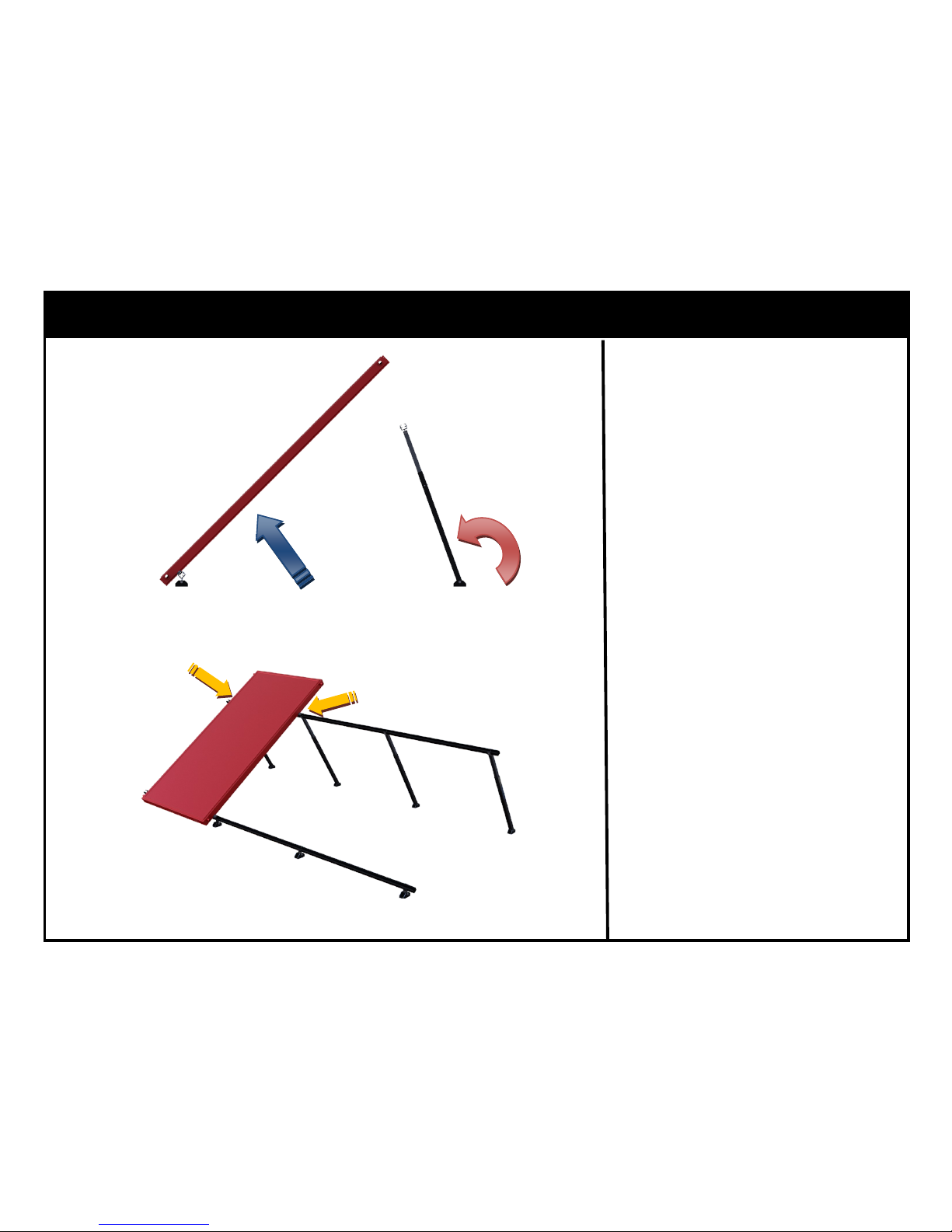
Figure 6
RexRack — First Collector Installation
4. Raise Collector.
5. Swing rear leg assembly and position the Upper Support Strut so
that it is 20% inboard of the Collectors top edge. As shown in
Figure 6.
6. Install two (2) C-SSN Collector
Mounting Assemblies on the Upper Support Strut and torque to
19 ft*lbs (26 N*m). As shown in
Figure 7.
Figure 7
Page 20
20
November, 2014 Rev.C
RexRack — Guide Rail Placement
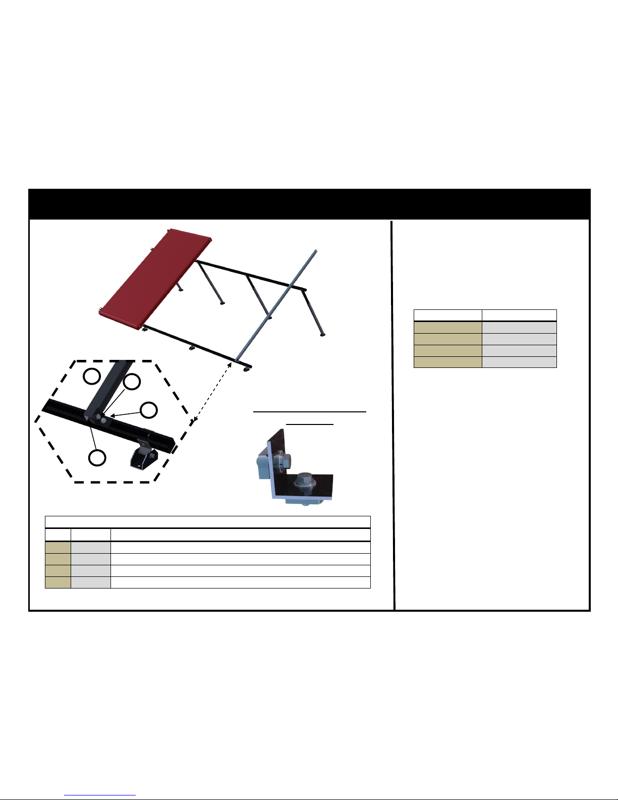
1. Attach Rail Brackets to the Rail,
using the scale integral to the
Rail, at the appropriate Collector
Support Strut spacing (x) and
torque to 19 ft*lbs (26 N*m).
2. Place Rail Brackets on Upper and
Lower Supports Struts and
torque to 19 ft*lbs (26 N*m).
3. Check that Upper and Lower
Support Struts are co-planar. If
adjustments are necessary the
three (3) Self Drilling Screws can
be removed from the telescoping
legs. Following which the legs
can be adjusted and the three
(3) Self Drilling Screws reinstalled.
Guide Rail Assembly Part # MTG-TS-BA
Qty. Descripon
7
1 ea. Rail (Black Anodized Shown)
8 4 ea. SSN-38 Fastener Assembly
9 2 ea. Rail Bracket (Black Anodized Shown)
9a 1 ea. Integral Scale
Table 3
7
8
9
Guide Rail Bracket with
Fasteners
SunEarth Collector # Support Strut Spacing (x)
EC/EP/SB-40-XX
91.75”
EC/EP/SB-32-XX 72.5”
EC/EP/SB-24-XX 72.5”
EC/EP-21-XX 50.125”
9a
Page 21
21
November, 2014 Rev.C
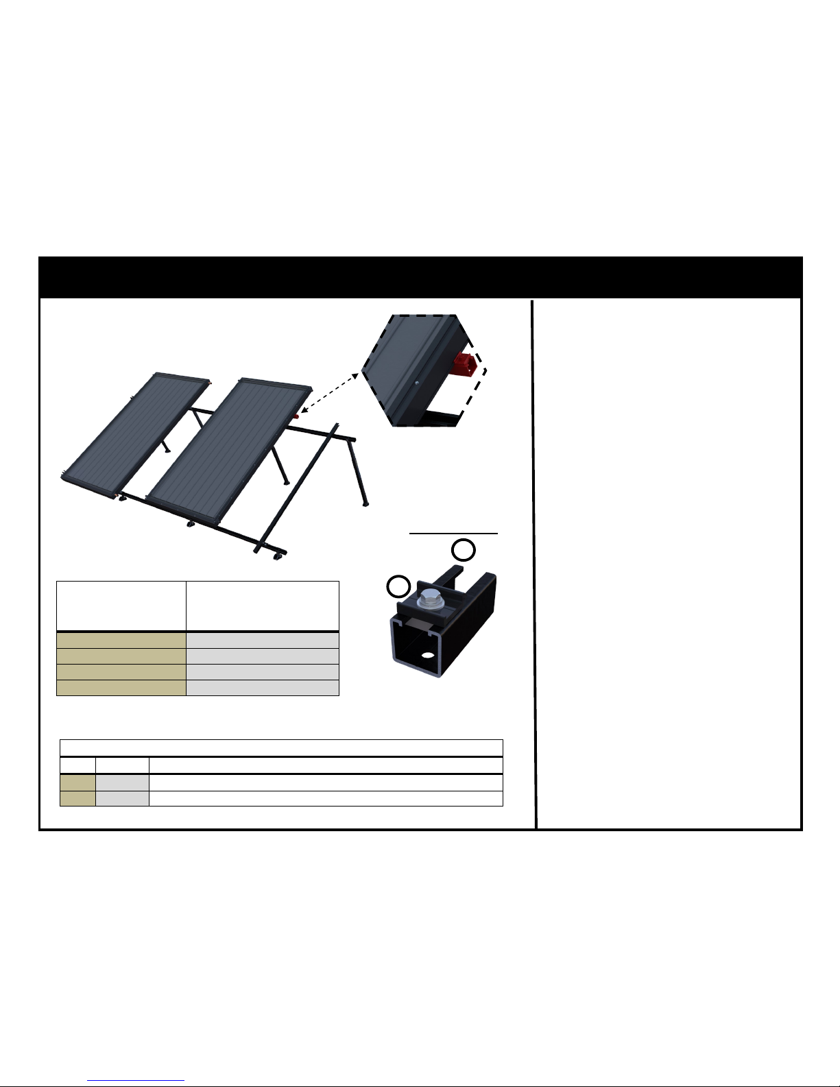
RexRack — Collector Helping Hand Placement
1. Install two (2) Helping Hands on
Collector per Table 4, shown in
RED. Torque to 19 ft*lbs (26
N*m).
2. Place Collector on Rack. Allowing
Collector to be supported by
Helping Hands.
Helping Hand Part # MTG-HH-BA
Qty. Descripon
10
2 ea. SolarStrut (Black Anodized Shown)
11 2 ea. C-SSN Collector Mounng Assembly
Table 5
SunEarth Collector #
Helping Hand Placement from
Upper End of Collector
EC/EP/SB-40-XX
22.75”
EC/EP/SB-32-XX 18”
EC/EP/SB-24-XX 18”
EC/EP-21-XX 13.625”
Table 4
10
11
Helping Hand
Page 22
22
November, 2014 Rev.C
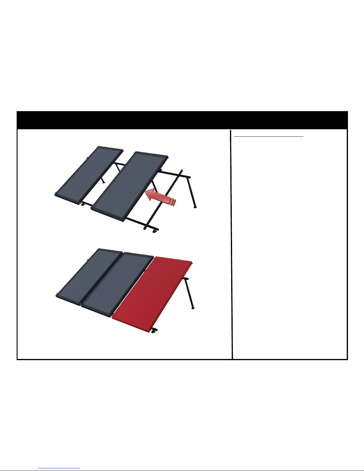
RexRack — Additional Collector Installation
1. Slip two (2) copper couplings on
the Collector headers.
2. Slide Collector into position while
aligning header couplings. As
shown in Figure 8.
3. With the Collector in position install four (4) C-SSN, Collector
Mounting Assemblies. Torque to
19 ft*lbs (26 N*m).
4. Sweat Copper Couplings.
5. Remove Helping Hands and install on the next Collector.
6. Follow steps 1-5 until the final
Collector, shown in RED, is installed prior to which the Guide
Rail is removed. As shown in Fig-
ure 9.
Figure 8
Figure 9
Copper Coupling Method
Page 23
23
November, 2014 Rev.C
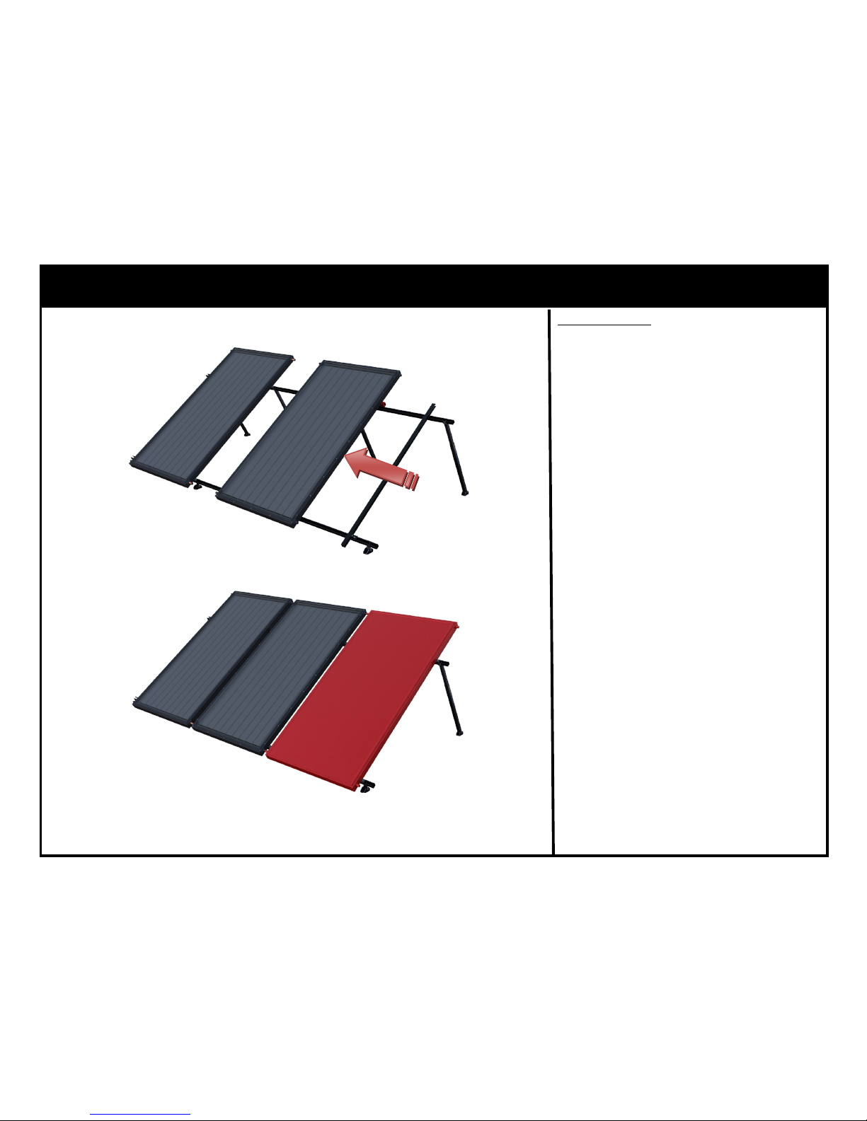
RexRack — Additional Collector Installation
1. Slide Collector into position while
aligning header Unions. As
shown in Figure 10.
2. Insert O-Rings and tighten Unions ensuring that O-Ring is not
damaged.*
3. With the Collector in position install four (4) C-SSN, Collector
Mounting Assemblies. Torque to
19 ft*lbs (26 N*m).
4. Remove Helping Hands and install on the next Collector.
5. Follow steps 1-5 until the final
Collector, shown in RED, is installed prior to which the Guide
Rail is removed. As shown in Fig-
ure 11.
Figure 10
Figure 11
Union Method
*Note: Always us a pipe wrench to back up
the Union when tightening in order to avoid
damaging the header pipe and internal riser
tubes.
Page 24
24
November, 2014 Rev.C
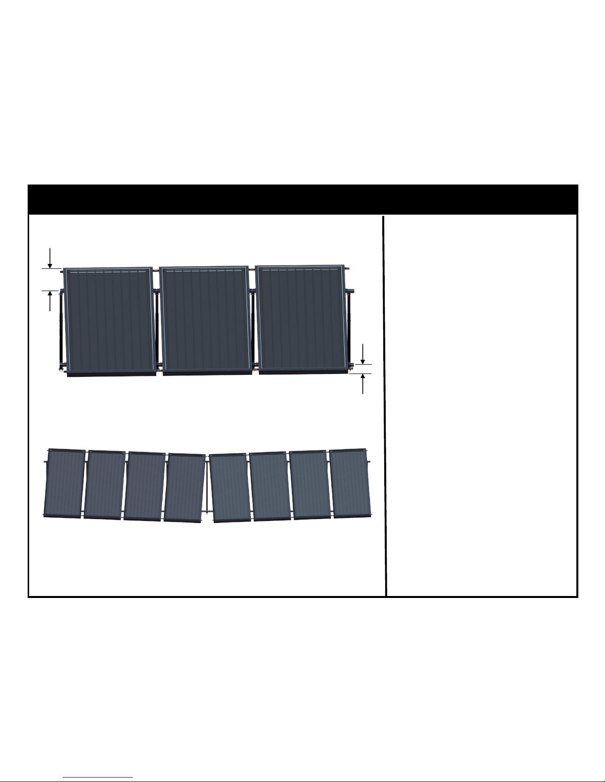
RexRack — Drainback Considerations
For drainback systems Collectors can
be angled in order to ensure the Collectors are fully drained when the
pump stops. As shown in Figure 12.
When angling Collectors a minimum
distance of 6” must be maintained
between the Collector ends and the
Support Struts.
In cases where many collectors are
to be placed in a single row the
skewing of the collectors can be mirrored to create a chevron pattern.
As shown in Figure 13.
Figure 12
Figure 13
6” MINIMUM
6” MINIMUM
Page 25
25
November, 2014 Rev.C
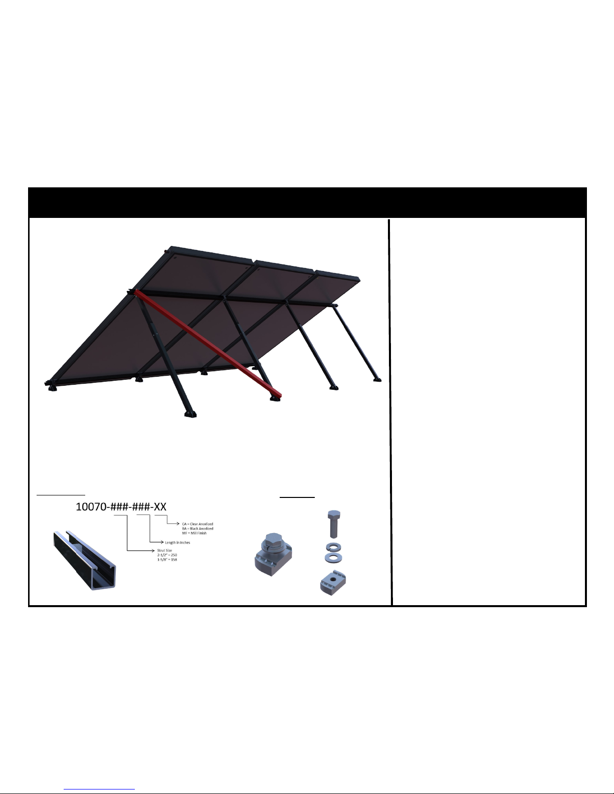
RexRack — Seismic Considerations
For installations where Seismic forces must be considered then the addition of a diagonal brace is required.. Shown as RED in Figure 14.
The brace consists of SolarStrut affixed to the RexRack Rear Telescoping Legs utilizing SSN-38 hardware
assemblies.
One (1) diagonal brace is required
for every six (6) Collectors in a continuous row.
Figure 14
SolarStrut
SSN-38
Page 26
26
November, 2014 Rev.C
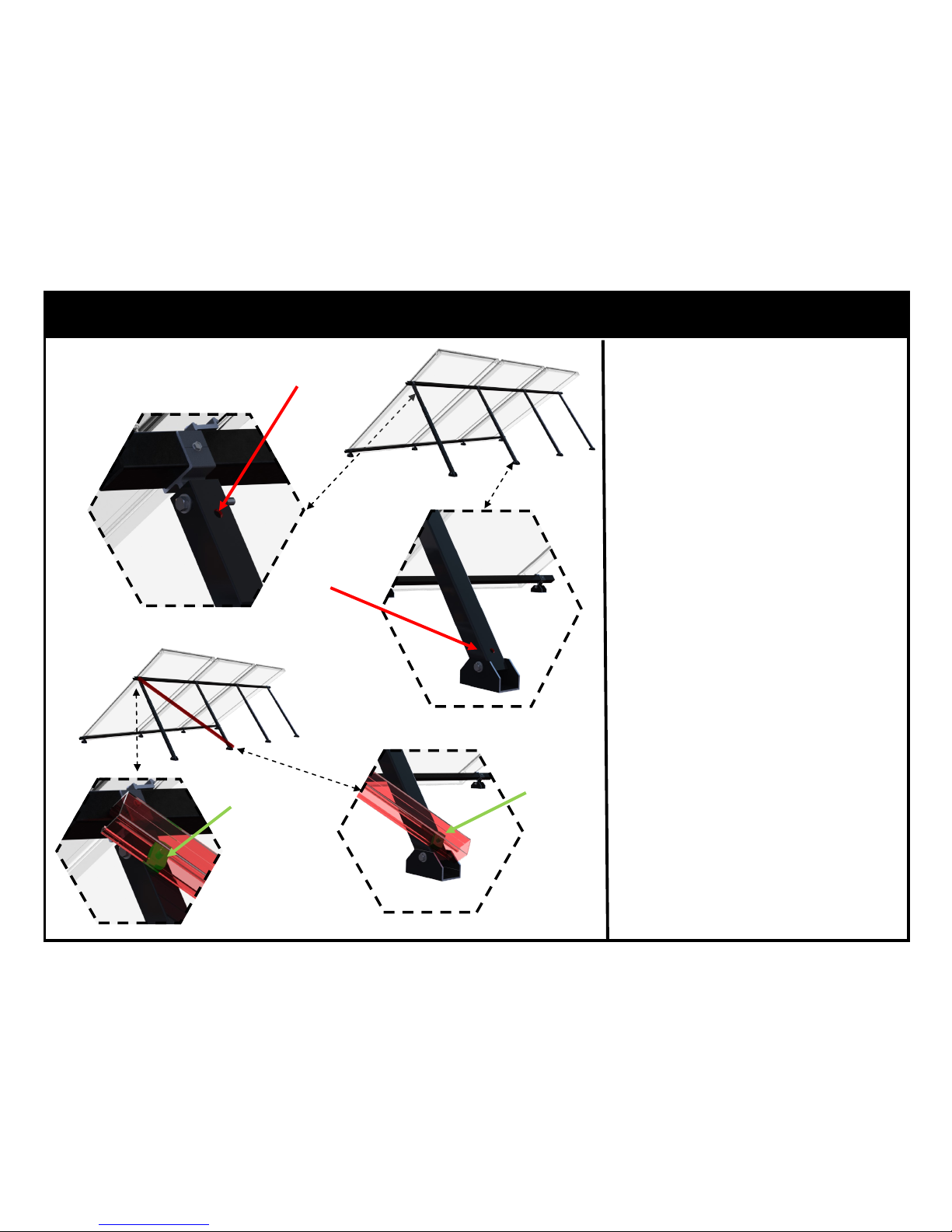
RexRack — Diagonal Brace Installation
Figure 15
1. Drill 3/8” hole 1-1/2” from the
top of the Rear Telescoping Leg
Slider. Shown as RED in Figure
15.
2. Drill 3/8” hole 1-1/2” from the
bottom of the adjacent Rear Telescoping Leg. Shown as RED in
Figure 16.
3. Install SSN-38 hardware assemblies in the drilled holes. Shown
as GREEN in Figures 17 & 18.
4. Slide SolarStrut onto SSN-38
hardware assemblies.
5. Torque SSN-38 hardware assemblies to 19 ft*lbs (26 N*m).
3/8” Hole
3/8” Hole
Figure 16
SSN-38
Figure 17
Figure 18
SSN-38
Page 27
27
November, 2014 Rev.C
LIMITED PRODUCT WARRANTY
This warranty only applies to the following SunEarth products (hereinafter SunEart h Products):
MOUNTING HARDWARE: SolarStrut, SunEarth Mounting Clips, Flush Mount Foot
TILT RACKS: RexRack, Universal Tilt Rack, Landscape Rack
Under conditions of normal use and service the above SunEarth Mounting Structures are warranted to the
original user at the original installation site to be free from substantial defects in material and workmanship
of the structural components of the products for a period of 10 years (Structural Warr anty Period) except of
the anodized finish, which will be free from visible peeling, cracking or chalking under nor mal atmospheric
conditions for a period of 3 years (Finish Warranty Period) pursuant to the exclusions detailed in this
written warranty statement. The warranty period for both structural and finish warranties shall be from the
date of sale to the end user. SunEarth's liability for these SunEarth Products shall be limited to rep airing or
replacing at SunEarth's sole option, without charge, F.O.B. SunEarth's factory o r an authorized SunEarth
distributor or service center. SunEarth will not be liable for any costs of transportation, inspection, remova l,
reinstallation, or any other labor or freight charges that may arise in connection with a warranty claim.
THIS WARRANTY DOES NOT APPLY
This warranty do es not apply to the following: (1) conditions resulting from a failed component or part
that is not part of the above listed SunEarth Products; (2) to conditions resulting from misuse, abuse,
neglect, accident, alteration or modification b y anyone other than SunEarth; (3 ) to damage occurring during
shipping, handling, storage or installation of the SunEarth Products; (4) to damage caused by installation
methods, including mounting, that do not confor m to relevant national, state or local co des and ordinances,
good industry practices, or to current applicab le SunEarth manuals, diagrams, technical b ulletins, or written
installation instructions; (5) to cosmetic discolor ation of the product; (6) to rust or corrosion of the
components; (7) to installatio ns in corrosive atmospheric conditions; (8) to foreign residue deposited on
the finish; (9) to conditions resulting from floods, earthquakes, winds, fire, lightning, snow, ice, hail or
circumstances beyond SunEarth's control; (10) to any cause unrelated to materials and workmanship.
The Finish Warranty is VOID if the practices specified by AAMA 609 & 610-02 – “Cleaning and
Maintenance for Architecturally Finished Aluminum” (www.aamanet.org) are not followed by Purchaser
for SunEarth’s aluminum based products.
The warranty does not cover any defect that has not been reported in writing to SunEarth within
ten (10) days after discovery of such defect.
If one of the above SunEarth Products is purchased outside the United States certain conditions of this
warranty may NOT apply. Please contact your local SunEarth distributor or d ealer for details.
LIMITED WARRANTY
EXCEPT AS EXPRESSLY PROVIDED IN THIS WARRANTY, THE ABOVE SUNEARTH
PRODUCTS ARE P ROVIDED WITHOUT WARRANTY OF ANY KIND, EITHER EXPRESS OR
IMPLIED, INCLUDING, BUT NOT LIMITED TO, THE IMPLIED WARRANTIES OF
MERCHANTABILITY AN D FITNESS FOR A PARTICULAR PURPOSE OR ANY WARRANTY
OR NON-INFRINGEMENT. SOME STATES DO NOT ALLOW THE EXCLUSION OF IMPLIED
WARRANTIES, SO THE ABOVE EXCLUSION MAY NOT APPLY TO YOU.
LIMITATIONS OF REMEDIES
IN NO EVENT SHA LL SUNEARTH BE LIABLE FOR ANY DAMAGES FOR LOST PROFITS,
LOST SAVINGS OR O THER INCIDENTAL OR CONSEQUENTIAL DAMAGES, ARISING OUT
OF THE USE OR INABILITY TO USE THE ABOVE SUNEARTH PRODUCTS, OR FOR ANY
CLAIM BY A THIRD PARTY. SOME STATES DO NOT ALLOW THE LIMITATION OR
EXCLUSION OF LIABILITY FOR INCIDENTAL OR CONSEQUENTIAL D AMAGES, SO THE
ABOVE LIMITATION MAY NOT APPLY TO YOU.
EXCLUSIVE AGREEMENT
THIS WARRANTY CONSTITUTES THE ENTIRE, COMPLETE, FINAL, AND EXCLUSIVE
AGREEMENT FOR THE SUNEARTH PRODUCTS LISTED ABOVE. THIS WARRANTY
SUPERSEDES ANY PROPOSAL, AGREEM ENT, OR REPSRESENTATION, OR ANY OTHER
COMMUNICATION, EITHER WRITTEN OR ORAL, MADE BETWEEN SUNEARTH AND
SUNEARTH’S DISTRIBUTORS OR DE ALERS, OR BETWEEN SUNEARTH AND THE END
CONSUMER.
TO MAKE A CLAIM
To obtain ser vice under this warranty, t he product i n question must be returned to the distributor or dealer
of SunEarth p roducts nearest you, or an authorized SunEarth service center. Each claim must be
accompanied by documentation providing the following:
1) Owner’s name, add ress, email address, and phone number
2) Installation contractor’ s name, email address, and phone number
3) Original sales receip t
4) Product model nu mber(s)
5) Date of installatio n
6) Date of failure
7) Reason for failure
8) Pictures of the suspected manufacturing defect – digital pictures of the suspected manufacturing defect
also need to be submitted
If you have any warranty questions, contact your installation contractor or SunEarth at (909) 434 -3100.
RexRack — Warranty
 Loading...