

Page 1
™
Page 2

Page 3

CASCADE DRAINBACK™
DOMESTIC SOLAR WATER
HEATING SYSTEM
INSTALLATION, OPERATION AND MAINTENANCE MANUAL
The Cascade Drainback solar water heating system has gone through an extensive design, technical and performance review by the Solar Rating & Certification Corporation (SRCC). The installation of your Cascade
Drainback system is intended to be executed by properly licensed and experienced professional contractors
in accordance with SRCC Standard OG-300, “Operating Guidelines and Minimum Standards For Certifying
Solar Water Heating”, and must conform to applicable federal, state and local regulations, codes, ordinances
and standards governing the installation of solar water heating systems.
The solar energy system described by this manual, when properly installed and maintained, meets the minimum
standards established by the SRCC. This certification does not imply endorsement or warranty of this product
by the SRCC.
OG-300 system certification is granted to SunEarth by the SRCC. It may not be used for any commercial purpose without the prior written consent of SunEarth. SunEarth must approve any deviation from the specified
materials and methods described in this manual in writing.
The Cascade Drainback solar water heating systems can be protected against freeze damage to temperatures as
low as -50ºF (-46ºC). This system should not be installed in areas within the continental United States where
the annual ambient temperature has ever fallen below minus 50° Fahrenheit (-46° Celsius). The Cascade
Drainback system must be installed as specified in this manual to have effective freeze protection at these low
temperatures.
Freeze tolerance limits are based upon an assumed set of environmental conditions. Extended periods of cold
weather, including ambient air temperatures above the specified limit, may cause freezing in exposed parts of
the system. It is the owner’s responsibility to protect the system in accordance with SunEarth’s instructions if
the ambient air temperature approaches the specified freeze tolerance limit.
Page 4

TABLE OF CONTENTS
Safety Information ............................................................................................................................1
Preface ................................................................................................................................................3
1) Introduction ..................................................................................................................................3
2) System Description and Operational Principle .........................................................................3
3) Installation Requirements – General .........................................................................................5
4) Installation Requirements – Specific ..........................................................................................5
5) System Start Up Procedures .....................................................................................................19
6) Two Modes of System Operation ..............................................................................................19
7) Isolating the Major Components and Shut Down Procedures ..............................................20
8) Summer Vacation Procedures ...................................................................................................20
9) Maintenance and Troubleshooting ...........................................................................................20
10) Cascade Drainback System Component Parts ......................................................................22
11) Estimated Component Life Expectancy .................................................................................23
Installation Manual
12) System Operating Parameters ................................................................................................23
Appendix A. OG-300 Approved Primary Components ..............................................................24
Appendix B. Pump Sizing Tables ..................................................................................................27
Appendix C. SRCC OG-300 Certified System Model Numbers ................................................29
Appendix D. Cascade Drainback OG-300 Labels .......................................................................30
Appendix E. SunEarth Collector Warranty Statement ..............................................................32
Page 5
Time/Temperature Relationship in Scalds
Temperature Time To Produce a Serious Burn
120°F More than 5 minutes
125°F 1½ to 2 minutes
130°F About 30 seconds
135°F About 10 seconds
140°F Less than 5 seconds
145°F Less than 3 seconds
150°F About 1½ seconds
155°F About 1 second
Table courtesy of Shriners Burn Institute
The chart shown above may be used as a guide
in determining the proper water temperature for your home.
!
DANGER: Households with small children, disabled,
or elderly persons may require a 120°F or lower thermostat
setting to prevent contact with “HOT” water.
NOTICE: Mixing valves should be installed to reduce the
point of use water temperature by mixing hot and cold water
in branch water lines. Contact a licensed installer or the local
plumbing authority for further information.
The temperature of the water in the water heater can be regulated by setting the temperature dial of the adjustable surface
mounted thermostat located behind the jacket access panel.
This thermostat controls the
water heater’s heating element only. (A separate thermostat should be utilized in
monitoring the temperature
from the collector).
To comply with safety regu
lations the thermostat is
factory set at 120° F or less
where local codes require.
!
DANGER: Hotter water increases the potential for Hot
Water SCALDS.
°
!
DANGER!
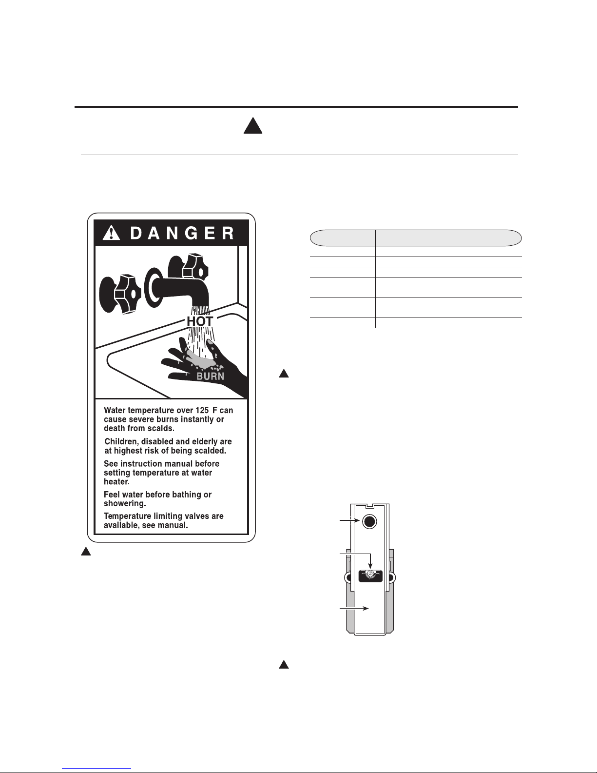
WATER TEMPERATURE SETTING
Safety and energy conservation are factors to be considered when selecting the water
temperature setting of water heater’s thermostat. Water temperatures above 125°F
can cause severe burns or death from scalding. Be sure to read and follow the warnings
outlined on the label pictured below.
!
DANGER: Burns from Hot Water and
Steam - Use extreme care when opening relief
valves, charging closed loop, and filling storage
tank.
The electrical element booster thermostat has
been factory set at 50°C (120°F) to reduce the
risk of scald injury. Adjusting the thermostat to a
higher setting is not recommended. Hotter water
increases the potential for Hot Water Scalds.
R
E
S
E
T
R
E
S
E
T
TURN OFF
POWER
BEFORE
SE RV ICING
90°F150°F
125°F
(66°C)
(52°C)
(32°C)
Reset button
Thermostat
protective
cover
Thermostat
dial pointer
IMPORTANT SAFETY INFORMATION.
READ ALL INSTRUCTIONS BEFORE USING.
P.1
Page 6
!
WARNING!
For your safety, the information in this manual must be followed to minimize the risk
of fire or explosion, electric shock, or to prevent property damage, personal injury, or loss
of life.
FOR INSTALLATIONS IN THE STATE OF CALIFORNIA
California Law requires that residential water heaters must be braced, anchored or
strapped to resist falling or horizontal displacement due to earthquake motions. For
residential water heaters up to 52 gallon capacity, a brochure with generic earthquake
bracing instructions can be obtained from: Office of the State Architect, 1102 Q Street,
Suite 5100, Sacramento, CA 95814 or you may call 916-445-8100 or ask a water heater
dealer.
However, applicable local codes shall govern installation. For residential water heaters
of a capacity greater than 52 gallons, consult the local building jurisdiction for acceptable
bracing procedures.
Have the installer show you the location of the circuit breaker and how to shut it off if
necessary. Turn off the circuit breaker if the water heater has been subjected to overheating,
fire, flood, physical damage or if the ECO fails to shut off.
Read this manual entirely before installing
or operating the water heater.
Be sure your appliance is properly installed
in accordance with local codes and the
provided installation instructions.
SAFETY PRECAUTIONS
Use this appliance only for its intended
purpose as described in this Installation,
Operations and Maintenance Manual
Be sure to read and understand the entire Installation, Operation and Maintenance
Manual before attempting to install or operate this water heater. It may save you time
and cost. Pay particular attention to the Safety Instructions. Failure to follow these
warnings could result in serious bodily injury or death. Should you have problems
understanding the instructions in this manual, or have any questions, STOP, and get
help from a qualified service technician, or the local utility.
Do not attempt to repair or replace any part
of your water heater unless it is specifically
recommended in this manual. All other
servicing should be referred to your installing contractor or local SunEarth Distributor.
IMPORTANT SAFETY INFORMATION.
READ ALL INSTRUCTIONS BEFORE USING.
READ AND FOLLOW THIS SAFETY INFORMATION
CAREFULLY.
SAVE THESE INSTRUCTIONS
P.2
Page 7

PREFACE
Let us first offer two words of grateful appreciation.
Thank You! We sincerely appreciate your business.
SunEarth also wishes to say thank you for “going
solar”. Solar water heating systems reduce our
nation’s dependence on polluting fossil fuels, minimize the greenhouse gas emissions associated with
conventional water heating and, very importantly,
lower your monthly utility costs.
Established in 1978, SunEarth is a leading U.S.
solar equipment manufacturer. Our products
include industry standard Empire, SunBelt, Imperial
and ThermoRay solar water heating collectors,
CopperHeart integral collector storage systems,
SunSiphon packaged thermosiphon systems,
SunBurst all copper absorber plates, Solar Strut
and “RexRack” mounting systems. We also build
specialty collectors for unique architectural and
building applications. SunEarth Solar Rating and
Certification Corporation (SRCC) Standard OG-300
certified solar water heating systems are sold by
leading solar, plumbing and building contractors
throughout the United States.
Your Cascade Drainback solar water heating system
has been designed to meet exacting SRCC OG-300
certification requirements. The specific components
found in your system have been selected by your
installation contractor for their proven reliability,
longevity and performance in your specific region
of the country.
SunEarth maintains a policy of continuous review
and improvement to ensure that Solaray systems
incorporate any appropriate technological advances.
To ensure that products represent the current state
of the art in solar water heating SunEarth systems
are subject to change without notice. Please consult
the SunEarth Inc. website at www.sunearthinc.com
for current information and latest manual revisions.
1) INTRODUCTION
Solar water heating systems are climate and site
specific appliances. Different types of solar systems are installed around the world in accordance
with regional weather and water quality conditions.
System performance varies as a function of the
household hot water load, including daily showers,
laundry and kitchen uses, the average ground water
and ambient air temperatures, the home’s roof pitch
and orientation, and, of course, the seasonal intensi-
ty of solar radiation. These variables, some of which
change from home to home on the same neighborhood street, will determine how much energy and
money your Cascade Drainback system will save on
an annual basis.
Your Cascade Drainback solar system is known as
a “forced circulation closed loop drainback” system
because it utilizes a mechanical pump to efficiently
circulate water throughout the unpressurized closed
loop solar piping. The “drainback” connotation
refers to the freeze-protection mechanism used in
the system. In drainback systems, the heat exchange
fluid (water) in the collector array and solar loop
piping drains back by gravity into the drainback
storage reservoir when the pump stops circulating.
Air replaces water in the collector array and solar
loop piping to prevent it from freezing when the
pump is off.
This manual is intended as a basic “solar water heating primer”. Our goal is to familiarize you with the
proper installation, operation, and maintenance of
your Cascade Drainback solar system. This system
is required to be installed by properly licensed solar
or plumbing contractors in accordance with SRCC
Standard OG-300 and all applicable national, state
and local codes, ordinances and regulations governing solar installations as well as good trade practices. Failure to follow the procedures and practices
described in this manual may void manufacturer
warranties for specific component parts.
This manual covers installations utilizing one or two
SunEarth solar collectors with a single solar storage
tank and also two tank systems that include a solar
storage tank and supplemental tank type or tankless
water heater. For simplicity, the singular form will
be used throughout this manual when referring to
the system components and permutations. Frequent
reference will be made throughout this manual to
specific component parts. The placement of each
component in the system is found in Figures 17, 18
and 19. An explanation of the component function
is found in pages 23-24.
2) SYSTEM DESCRIPTION AND
OPERATIONAL PRINCIPLE
The key components in the Cascade Drainback solar
water heating system include the SunEarth solar collector, drainback reservoir, solar storage tank with
integral heat exchanger, circulation pump, differential temperature controller and mixing valve.
P.3
Page 8
The SunEarth solar collector is the heart of the
Cascade Drainback system. Simply stated, when the
sun is shining, heat energy is absorbed by the solar
collector’s all copper absorber plate and transferred
to the water circulating through the solar collector.
The system pump efficiently circulates this heated
water through the collector piping and integral tank
heat exchanger. As the water passes through the
heat exchanger, the heat in the fluid is transferred to
the potable water in your solar storage tank. As this
process is repeated during the average sunny day,
the temperature in your solar storage tank rises.
The differential temperature controller is the brain
of the system. The controller uses temperature sensors to constantly monitor the temperatures at the
collector and at the tank. The controller automatically turns the pump on when useful heat is available at the collector and turns the pump off when
there is insufficient solar heat available or the tank
has reached maximum temperature.
or gas water heater or (2) be bypassed entirely and
run 100% on utility power during inclement weather
or when maintenance is required. The installation of
an optional water heater time switch allows you to
control both the frequency and duration of supplemental electric resistance water heating.
Section 6 provides instruction in setting the system
for automatic operation in each of these two modes.
The water in the SunEarth collector and the solar
loop piping automatically drains back into the
drainback reservoir each time the circulating pump
turns off. Gravity drains the piping and provides
the freeze and overheat protection for your Cascade
Drainback system.
The system also can be manually drained in order to
protect the integrity of the collector and solar loop
piping if it is exposed to extended periods of disuse
or persistent hard freeze conditions below - 50°
Fahrenheit. (See Section 7 for instructions).
Depending upon the system demand, time of year
and the weather, the circulating pump may either
run intermittently throughout the day or constantly
for hours at a time.
Both single and double tank Cascade Drainback
systems are designed to accommodate two separate
modes of system operation. Your system can either
(1) serve as a preheater to your conventional electric
fig. 1
3) INSTALLATION REQUIREMENTS –
GENERAL
3.1 Permits:
The contractor shall obtain all required permits and
approvals.
3.2 Codes, Ordinances and Standards:
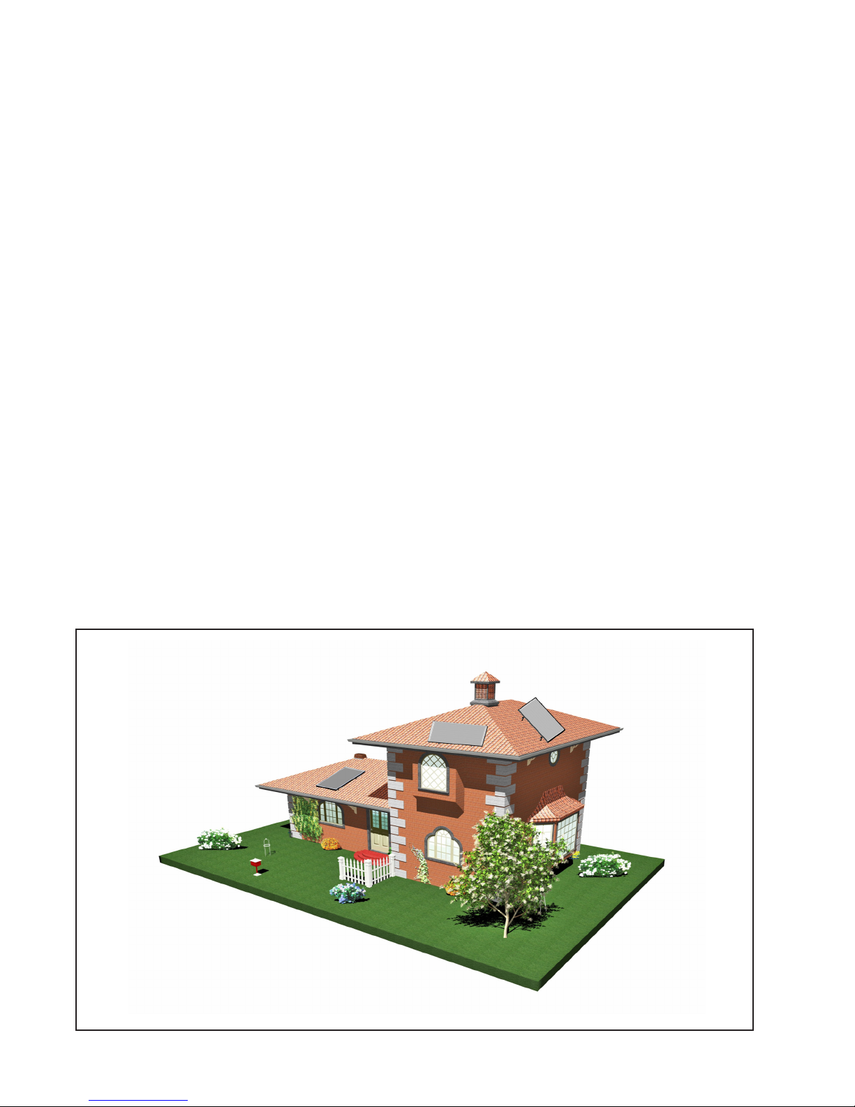
SYSTEM ORIENTATION
P.4
Page 9

The installation shall conform to all federal, state
and local regulations, codes, ordinances and standards governing the installation of solar water heating systems. The contractor shall adhere to sound
building safety and trade practices. Special consideration must be given to building code requirements
for roof loading and the penetration of structural
members and fire rated assemblies.
3.3 Shading Considerations:
The collectors must be located in an area of the roof
that will not be shaded for the majority of the day all
year round. Adjacent build¬ings and trees should
be checked for possible winter shading. The collector should not be shaded by any permanent obstacle
between 9:00 a.m. and 3:00 p.m. on any day of the
year. An instrument such as the Solar Pathfinder
can be used for solar site analysis.
3.4 Roof and Site Inspection:
Before the installation, the contractor shall inspect
the condition of the roof and notify the homeowner
of any existing roof damage or necessary repairs.
3.5 Structural Considerations:
The collectors must be located in a structurally
sound area of the roof. Penetrations into structural
members must not compromise the structural properties of the structural member.
ENSURE THAT ALL STRUCTURAL
MEMBER PENETRATIONS COMPLY WITH
APPLICABLE CODES.
The collector mounting method must be capable of
maintaining the required tilt and azimuth of the collector under the expected dead loads, wind loads and
snow loads for the location.
3.6 Building Envelope:
Penetrations through the building envelope (including roof, walls or floor penetrations) must not impair
the enclosure function and must meet applicable
codes and best practices.
Roof penetrations whether for structural mounts or
pipe penetrations must be sealed and leak proofed
as per applicable codes and National Roofing
Contractors Association practices.
Building penetrations must allow vermin intrusion.
3.7 Fire-Rated Assemblies:
Penetrations through fire-rated components must
not reduce the fire resistance of the assembly below
code.
3.8 Building Materials:
Building materials adjacent to solar components
must not be exposed to elevated temperatures.
3.9 Confirmation of Installation Site:
The homeowner and contractor shall confirm the
location of all roof and ground mounted components
in advance of the installation.
3.10 Fluid Identity and Toxicity:
The Cascade Drainback system uses water as a heat
transfer fluid, this is heated in the collector and
indirectly heats the domestic hot water through the
integral heat exchanger in the solar tank. Use of
toxic heat transfer fluids is prohibited.
3.11 Maintenance and Servicing
When installing the system, make sure that all the
components all the components are accessible and
easy to reach. Provide for clear access to the storage
tank, pump, drainback reservoir, mixing valve and
other key components. If a component in the potable
water side of the system may require future service
or maintenance make the connections with brass
unions or other approved connections.
4) INSTALLATION
REQUIREMENTS – SPECIFIC
4.1 Collector Orientation
The performance of solar water heating systems in
the Northern Hemisphere is optimized when the collector is mounted facing True South. Performance,
however, suffers very little when the collector is oriented no more than 45° East or West of True South.
The collector should be unshaded by any permanent
obstacle between 9:00 a.m. and 3:00 p.m. on any
day of the year.
4.2 Collector Tilt
Optimal annual efficiency is achieved by tilting the
solar collector at an angle that equals your latitude
plus an additional 10°. This tilt angle favors the
lower winter sun when collector performance is at
its lowest and minimizes overheating during the hot-
P.5
P.5
Page 10
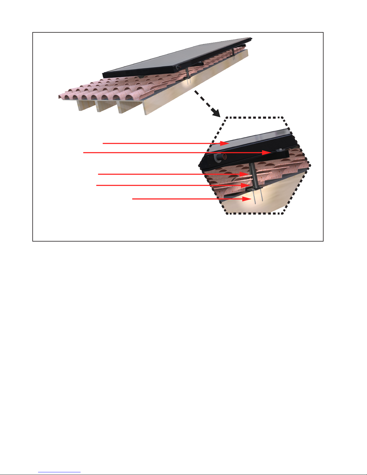
COLLECTOR
C-SSN
STAND OFF
FLASHING
STAINLESS LAG BOLT
fig. 2
STAND OFF ON BARREL TILE ROOF
test summer months.
To ensure proper water drainage from the glazing
of the collector, the collector must be sloped from
horizontal. Never mount the collector parallel to a
flat roof. Use SunEarth RexRack, Landscape rack
or Universal tilt products to tilt the collector to the
proper angle
The minimum acceptable tilt angle from horizontal
is 15°.
4.3 Basic Mounting Procedures
The SunEarth solar collector in your Cascade
Drainback solar system should be mounted in a
vertical orientation parallel to the slope of the roof
if possible. This orientation allows the internal riser
tubes to rapidly drain when the circulation pump
shuts off.
CRITICAL: BOTH THE COLLECTORS
AND THE SOLAR LOOP PIPING MUST BE
SLOPED TO DRAIN AWAY FROM THE
HIGHEST POINT IN THE SYSTEM BACK
TO THE DRAINBACK RESERVOIR.
The minimum required slope is 1/4” vertical drop
per foot of horizontal piping run (2% minimum
slope). Use the steepest slope possible on the return
line piping to the drainback reservoir. Water will
drain down both the return tubes directly to the
drainback reservoir and the supply tubes by spinning the pump impeller in the reverse direction.
The collector should be mounted as close to the storage tank as possible to minimize heat loss in the piping runs. The solar collector should be mounted on
the roof in accordance with these general principles:
4.3.1 The most important structural consideration
is to securely anchor the solar collector and the
SunEarth mounting hardware to the structural members of the roof with stainless steel hanger bolts,
lag bolts, standoff mounts or other approved roof
attachment method. The solar collector shall be
attached to the mounting hardware as detailed in
Figures 2 – 4. (Note: The drawings in this manual
detail mounting hardware for the SunEarth Empire,
Imperial, SunBelt and ThermoRay series collectors).
4.3.2 The collector should be raised from the roof
surface to allow for rainwater and debris to pass
P.6
Page 11
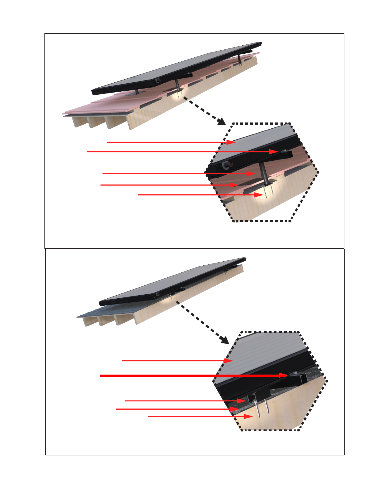
COLLECTOR
C-SSN
STAND OFF
FLASHING
STAINLESS LAG BOLT
fig. 3
STAND OFF ON FLAT TILE ROOF
COLLECTOR
C-SSN
FOOT MOUNT
FLASHING
STAINLESS LAG BOL
fig. 4
STRUT ON FOOT MOUNT FOR COMPOSITION ROOF
P.7
P.7
Page 12
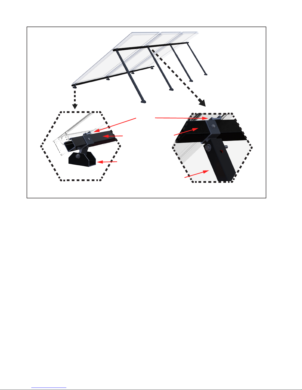
C-SSN
SUPPORT STRUT
FRONT
MOUNTING FOOT
fig. 5
REAR TELESCOPING LEG
REXRACK
under the collectors and for proper ventilation of
the roofing material. There should be at least 1 ½”
of clearance between the roof surface and the bottom of the solar collectors. Local codes may require
greater clearance for snow shedding, etc.
4.3.3 When selecting mounting hardware and fasteners it is extremely important to avoid galvanic
corrosion resulting from the direct contact of incompatible metals. Use of SunEarth anodized aluminum
Solar Strut mounting hardware and stainless steel
lag or hanger bolts, and fastening hardware is recommended. In climates subject to severe winters
or high humidity use of galvanized fasteners is
prohibited.
4.3.4 Preserving the integrity of the roof membrane
is the most important roofing consideration. Ensure
that all roof penetrations required to plumb and
mount the solar collector are properly flashed and
sealed in accordance with best roofing practices.
4.3.5 If the region is subject to hurricane conditions, additional steps may be required to secure
the collector and mounting hardware to the structural members. In certain areas of the country, local
building codes may require collector wind load
testing or prescribe specific mounting procedures.
Consult your local building department.
4.4 Collector Loop Plumbing
The collector loop must be plumbed using copper
or stainless steel piping and copper, brass, bronze
or stainless steel fittings. Lead-free solder shall be
used. Use of galvanized steel, CPVC or PVC is prohibited. PEX may be used only in systems that meet
the following conditions:
•
The PEX tubing shall not be exposed to sunlight.
•
Water must be used as the heat transfer fluid.
•
The system shall be non-pressurized (capped at
atmospheric on the day of installation) or shall be
vented to atmosphere.
A length of uninsulated copper tube no less than ¾”
nominal diameter shall be used at the hot outlet of
the solar collector(s) for a distance of no less than
three feet (3’) before the transition is made to PEX
tubing.
P.8
Page 13
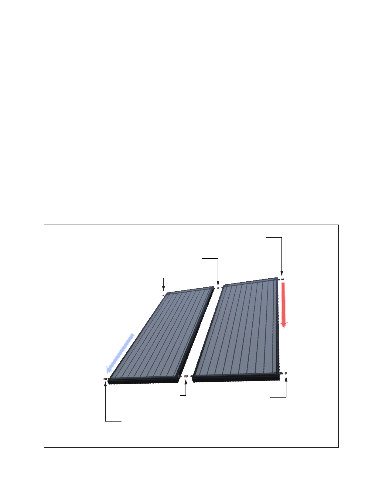
All connections in the PEX piping runs shall be
Supply Line
1” CC CAP
1” CC COUPLING
1” x ¾” CC 90° ELBOW OR COUPLING
RETURN LINE
1” x ¾” CC 90° ELBOW OR COUPLING
1” CC CAP
1” CC COUPLING
approved by the PEX manufacturer for potable
water piping.
•
The system shall have a pressure-only relief valve
installed at the drainback tank location or shall be
vented to the atmosphere. The pressure rating for
the relief valve shall be no less than 25 psi and no
more than 50 psi.
The collector loop pipe sizing must be adequately sized to handle the design flow rates for the
collector(s). SunEarth recommends ¾” nominal
diameter pipe sizes for two collector systems and
½” nominal diameter pipe sizes for two collector
systems, except for the return piping from the collector to the drainback reservoir, this should always
be ¾” or larger.
CAUTION: The solar loop piping from the
collector(s) to the drainback tank must be no less
than 3/4” TYPE-M copper tube to allow air to
migrate up the tube ensuring full draining of the
collector(s) and tubes.
It may be necessary to increase the pipe size for longer pipe runs or reduce the pipe size for shorter runs
or higher efficiency pumps. The pipe must be large
enough that the velocity of the water in the pipe does
not exceed 4 ft/s. Hot water flowing at over 4 ft/s
in a pipe will erode the pipe and reduce system life.
When more than one collector is used in the system,
the collectors should be plumbed in a reverse return
piping arrangement in order to maintain equal flows
through all collectors in the array during normal
operation.
To ensure proper drainage of the collector array
and solar loop piping the lines must be adequately
sloped to drain back to the drainback reservoir.
Figure 6 illustrates correct and incorrect methods of
plumbing the solar collector array. Note that water
will trap in the “U” section of piping as illustrated
in the drawing marked incorrect thus making it susceptible to freeze damage.
Piping in new solar installations can be covered with
dirt, grease, solder flux or other impurities that may
fig. 6
COLLECTOR PLUMBING - SLOPED TO DRAIN
P.9
Page 14

affect the system performance. A thorough cleaning is required before charging. A Water soluble
flux should be used when soldering pipe joints in
the collector loop in order to facilitate system flushing. Carefully review the cleaning procedures in
“Charging the System” outlined below.
All vertical piping between the storage tank and
the collector shall be supported at each story or at
maximum intervals of ten feet (10’). Horizontal
runs shall be sloped to drain (minimum 2% slope)
and supported every five feet (5’) to prevent sagging. Roof runs shall be secured and supported
providing at least 1-1/2 inches clearance from roof.
Pipe supports shall be constructed from a material
that will not rot, compress or degrade over time
as this may lead to pipe sagging and failure to
drain. Standard best piping practices shall be followed as described in the Uniform Plumbing Code,
International Plumbing Code or other recognized
code or standard. Plumbers tape or tube strap is
required. The pipe insulation should not be compressed or crimped by the strapping material.
have a maximum operating temperature of 220°F or
higher and a minimum thermal resistance of R-2.6.
The wall thickness of the pipe insulation should be
½” or thicker. A 1” wall thickness is required for
exposed piping in all areas prone to annual hard
freeze conditions. When it comes to pipe insulation
the rule is simple: thicker is better.
To the extent possible, slide the insulation material
over the pipe without cutting or taping. All butt
joints must be sealed with contact adhesive. The use
of rigid polyethylene pipe insulation is prohibited.
The temperatures generated by your collector in the
summer months or under stagnation conditions can
melt this type of material.
Any above ground exterior pipe insulation shall be
protected from UV degradation and moisture damage. Insulation must be jacketed, wrapped with aluminum foil tape, or painted with two coats of high
quality water-based acrylic resin coating as supplied
by the insulation manufacturer.
4.6 Control System
Allowance should be made for expansion and contraction of piping due to changes in temperature of
the water and piping. Use flexible pipe supports and
avoid long straight piping runs. Include bends and
elbows to allow for expansion such as swing joints
at the collector inlet & outlet.
The installation of all horizontal and vertical piping
may not reduce the performance or rating of any
structural member or fire rated assembly. Adhere to
all applicable local codes and ordinances.
4.5 Pipe Insulation
WARNING: HOT PIPES MAY CAUSE
BURNS IF TOUCHED. ENSURE THAT
ALL PIPES AND FITTINGS ACCESSIBLE
TO THE PUBLIC ARE WELL INSULATED.
COMPONENTS ACCESSIBLE TO PUBLIC
TRAFFIC MUST BE KEPT BELOW 140ºF
OR CLEARLY LABELLED WITH AN
APPROPRIATE WARNING.
The collector loop piping, plus any interconnecting
hot water piping shall be well insulated with a high
quality flexible closed cell insulation to minimize
heat loss. In addition, the final 5 feet of metallic
cold water supply pipe leading to the system, or
the length of piping which is accessible if less than
5 feet, shall also be insulated. The insulation shall
4.6.1 Differential Controller
The differential controller must be installed in an
accessible location so that the user interface, typically and LCD screen, can be seen. Switches on the
controller must be labeled and accessible. Always
follow the controller manufacturers wiring diagram
when installing differential controllers. Control system inputs; such as signals from temperature sensors
or flow meters will be connected to the appropriate
low voltage terminals. Controller output to the
pump will be medium voltage, 110 VAC or 220
VAC. Medium voltage power to the pump may be
supplied by a line cord from the pump to an outlet
in the controller or hard wired from the controller
medium voltage terminals to the pump. Wiring
must comply with standard electrical practice and
all applicable electrical codes for the jurisdiction,
this may require the use of conduit for medium voltage wiring.
The differential controller must have a provision to
manually turn the pump on and off (manual override) so that pump operation can be checked at
any time and the pump can be manually stopped if
required for maintenance or troubleshooting purposes.
P.10
Page 15
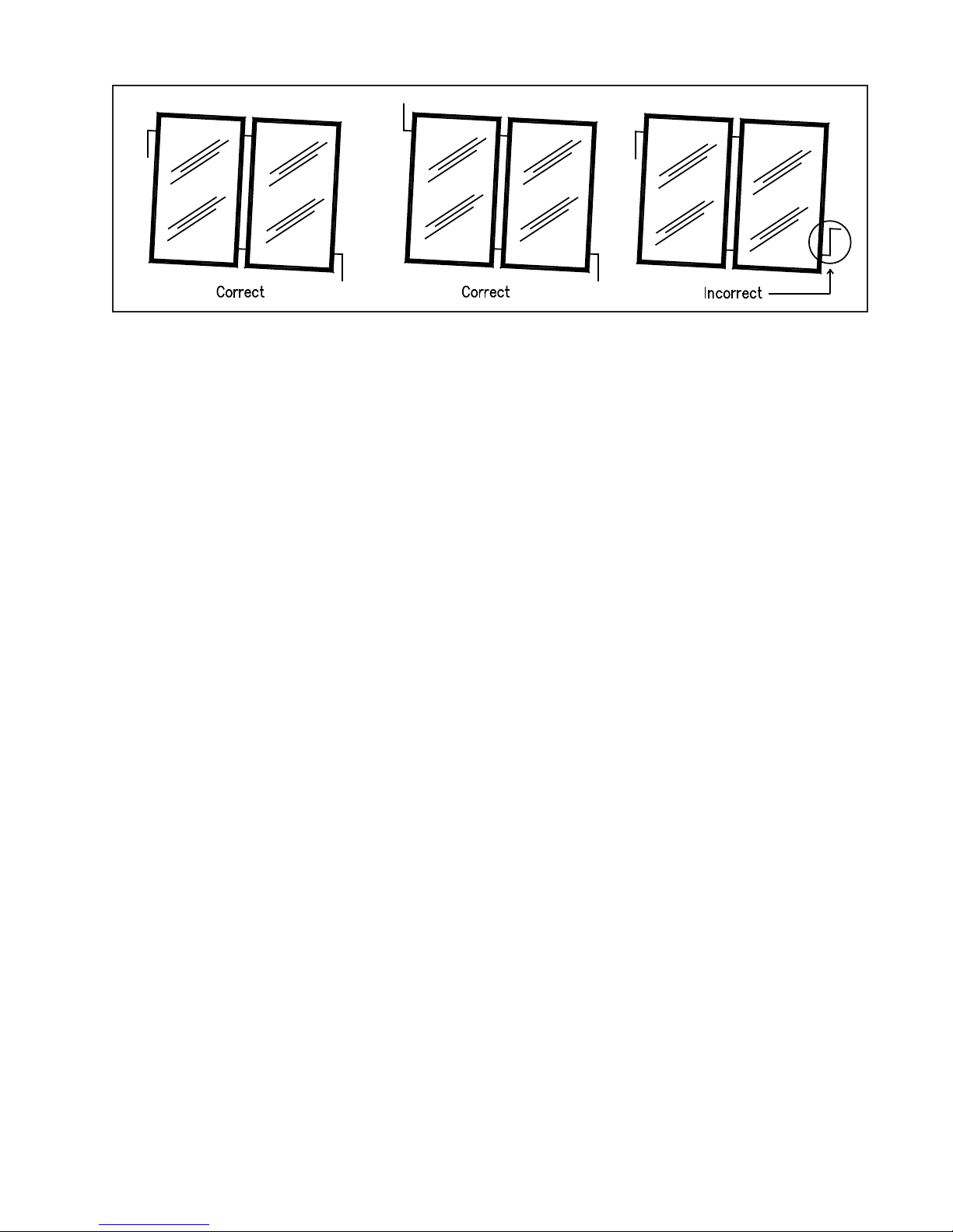
fig. 7
Set the maximum tank temperature to the desired
maximum temperature, this temperature must be
lower than the rated maximum temperature of the
tank. When the solar loop heats the tank to this temperature, the pump will shut off preventing further
heat gains to the solar tank.
4.6.2 Collector Sensor Placement
The collector sensor shall be located on the hot
water return line as close to the collector as possible.
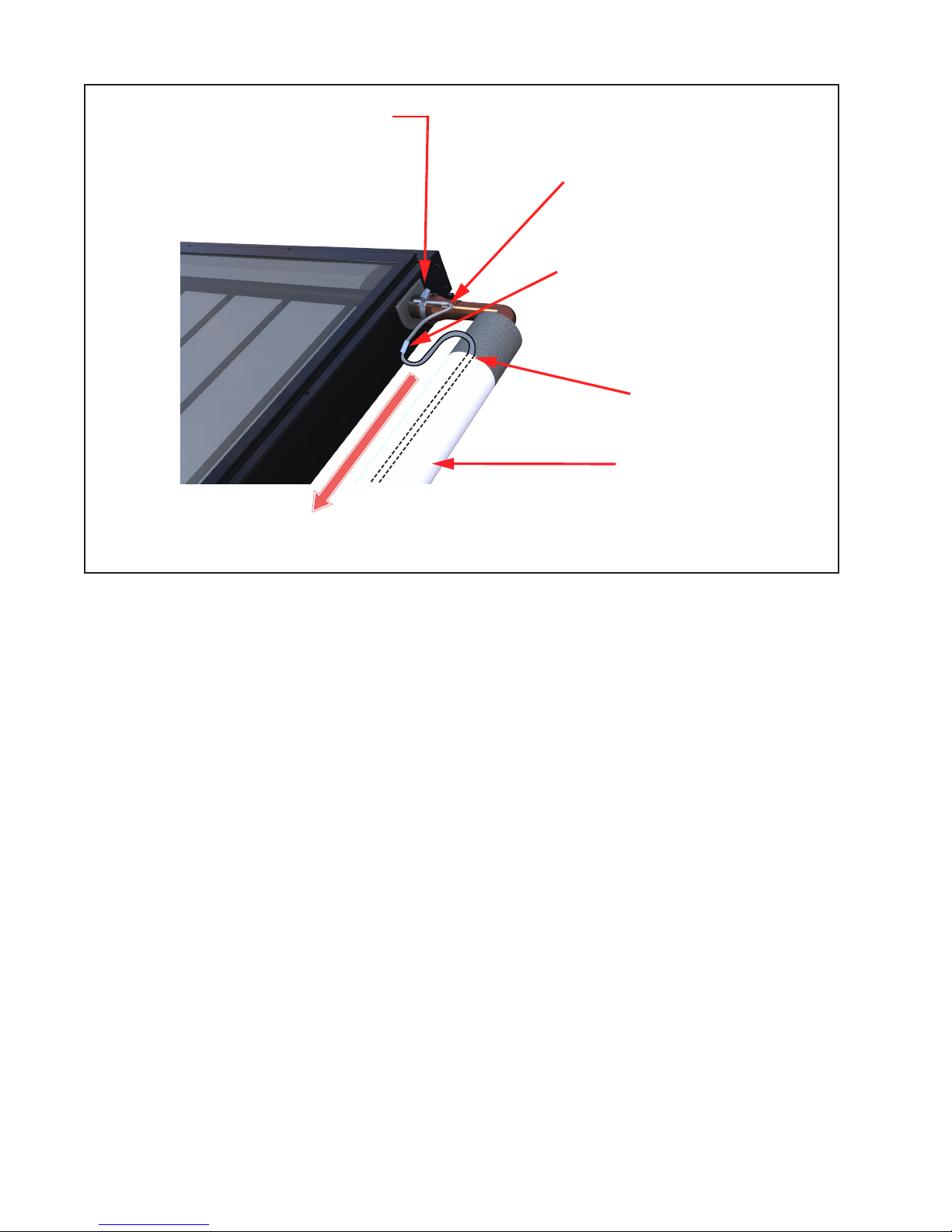
Sensors are typically accurate to +/- ½°F if properly installed and weatherized. The collector probe
sensor shall be attached to the SunEarth collector
header pipe either with a stainless steel hose clamp
or by inserting the probe sensor into a thermalwell
in contact with the fluid near the outlet header pipe.
It is recommended that the connection between the
silicon sensor lead and low voltage sensor wiring be
made inside the attic or other indoor space. When
using wire nuts to make the connection, the crimped
brass cap on the end of the sensor wire should be
striped before inserting into the wire nut. Where
connections from the sensor lead to the low voltage wiring is made at an exposed location the wire
connection should be protected from degradation
or corrosion from rain, snow and UV radiation.
Connections may be protected by using: crimp and
heat shrink or solder and heat shrink butt connections; NEMA 4X or other weather resistant connection boxes. Weather resistant connection boxes with
integral lightening arrestors are also available and
are highly recommended in areas prone to electrical
storms. Wire nuts or screw connectors should not
be exposed to weather due to the likelihood of corrosion which will result in a compromised electrical
connection.
Thoroughly wrap and weatherize the insulation with
electrician’s tape or insulation tape as provided by
the manufacturer. See Figure 8 for collector sensor
installation detail.
If an electrical potential exists between the roof
and ground, this may induce current to flow down
the sensor wire to the controller. This current will
result in a false signal being received by the controller and incorrect temperature readings. To prevent
such current the copper plate and piping should be
independently grounded. This will provide a separate path to ground from the roof which does not
interfere with the sensor readings.
Grounding can be achieved by running a separate
ground wire to the collectors or ensuring that the
copper pipe in the closed loop is grounded and there
are no electrical discontinuities between the grounding point and the collector. Grounding of the collector & roof piping is especially important in locations
that often experience electrical storms and electrical
atmospheric activity.
4.6.3 Low Voltage Wiring
The low voltage wiring used to connect the sensor
lead to the controller shall be a minimum18 AWG.
The wiring should be bare or tinned copper, two
conductor, stranded, PVC insulated, with a PVC UV
rated jacket suitable for exterior use. In locations
that often experience electrical storms and electrical atmospheric activity the low voltage sensor wire
should also be shielded and the shielding connected
to ground.
Low voltage wire shall be rated for the full range
of temperatures expected in the location, typically
wire should be rated up to 160ºF. The low voltage
sensor wire must not be in direct contact with the
copper pipe as the wire insulation may melt when
in contact with hot pipe. Low voltage sensor wire
must be run OUTSIDE the pipe insulation, where
the low voltage wire is run in an exposed location,
P.11
Page 16
PROTECTIVE INSULATION
JACKET OR APPROVED
COATING
RETURN LINE
CRIMP OR SOLDER
CONNECTION
SENSOR WIRE MUST
NOT BE PLACE IN
DIRECT CONTACT WITH
PIPE
SILICON SENSOR LEAD MAY
BE IN CONTACT WITH PIPE
SENSOR CLAMPED TO HEADER PIPE
& COVERED WITH INSULATION
COLLECTOR SENSOR
fig. 8
it should be run OUTSIDE the pipe insulation but
UNDER the insulation jacket or wrap to protect the
wire from UV exposure.
4.7 Installing the Solar Tank
The solar tank is heated indirectly through a double
wall heat exchanger that is integral to the tank. This
kind of heat exchanger wraps around the tank shell
and under the insulation and tank jacket. Any leak
in the heat exchanger will be seen as fluid will leak
out from the bottom tray of the tank jacket.
When plumbing the SunEarth solar storage tank and
drainback reservoir make sure that all the components are accessible and easy to reach. Ensure that
there is clear access to the storage tank, circulating pump, drainback reservoir, mixing valve, flow
meter and other key components. If a component
in the potable water side of the system may require
future service or maintenance make the connections
with brass unions. Use only brass nipples and unions
and copper and brass fittings in plumbing the solar
storage tank and drainback reservoir. The use of
galvanized fittings or nipples, CPVC or PVC piping
is prohibited.
P.12
Check valves are NOT ALLOWED anywhere in
the collector loop. A check valve in the collector
loop will prevent proper draining of the collectors
and may result in freeze damage. If the pump used
has an integral check valve, the check valve must be
removed before installing the pump in the system.
Hard copper connections to the city cold water
supply line and the home hot water feed lines are
recommended. The gaskets in standard water heater
flex hose connectors can become brittle and compressed over time and begin leaking on the water
heater. If not detected in a timely manner even a
small drip or leak may cause serious damage to the
tank’s electrical components or, in extreme cases,
may cause the tank to leak from the outside in.
Tank plumbing is required to provide for the isolation of the solar storage tank from the city cold water
supply line by means of an isolating ball valve.
The differential temperature controller shall have a
screen readout to show temperatures of the collector and storage tank. Otherwise, line thermometers
shall be installed in the collector supply and return
lines to allow for a simple diagnostic check of
proper system operation. On a sunny day the hot
water return line should be approximately 5 – 15°F
Page 17
warmer than the water in the collector supply line.
The specified SunEarth controller continuously
displays the temperature of the SunEarth collectors
(T1) and the temperature at the bottom of the solar
tank (T2). In addition, you may choose to install
a third temperature sensor (T3); this is normally
installed at the hot water outlet on both single and
double tank systems.
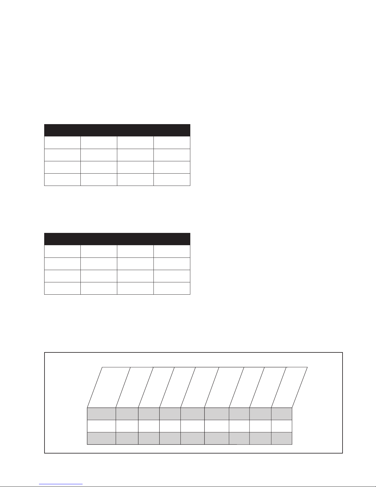
Table 1
Array DB 5.0 DB 7.5 DB 10.0
1 EP/EC-40 82 138 194
2 EP/EC-21 76 132 188
2 EP/EC-32 73 129 185
2 EP/EC-32 62 118 174
Pipe run lengths for 1/2” supply and 3/4”
return lines.
mum head on the pump curve must be greater than
the static lift head required to fill the system. The
static lift head is the vertical height from the bottom of the drainback tank to the highest point in the
system (usually the collector outlet header). When
the pump is filling the system it will be pumping
against the static lift head and should provide no
less than half the design flow of the collector. Once
the system has been filled to the top of the collector,
water will start to cascade down the return line filling the return line as far as the drainback reservoir.
Once this pipe is fully flooded the return line will
start to siphon, resulting in an increase in flow as
the system transitions from the filling condition to
the running condition. In the running condition the
flow rate should not exceed 4 ft/s. Good pump selection requires that the pump provide enough lift for
the filling condition without excessive flow in the
running condition. This is usually achieved using
a pump with a “steep” pump curve. For multistory
buildings, this can be especially challenging unless
the drainback tank is located on the upper floor.
Table 2
Array DB 5.0 DB 7.5 DB 10.0
1 EP/EC-40 61 103 144
2 EP/EC-21 57 98 140
2 EP/EC-32 54 96 138
2 EP/EC-32 46 88 130
Pipe run lengths for 3/4” supply and return
lines.
The Cascade Drainback system typically requires a
high head, low flow circulating pump. The maxi-
Table 3 - Specification For SunEarth CopperStor Drainback Tank
.
idth
SunEarth
odel No
M
W
Inches
Length
Inches
Depth
Inches
When there is a risk of pipe errosion due to high
flow rates, a pump throttling valve (COMPONENT
#22) may be located on the discharge, or upstream,
side of the pump to adjust the solar loop flow rate
and to prevent errosion of solar loop. A throttling
valve on the return piping from the collector to the
drainback tank can also be beneficial in situations
where excessive noise is experienced due to high
flow rates into the drainback reservoir.
A brass boiler drain (COMPONENT #11) must be
installed at the lowest point in the system to allow
for charging the solar loop piping and to serve as a
drain valve for manual draining and maintenance.
)
eight
(US gal
Wet
W
(lbs)
Max Pressure
(psig)
Connection
Pipe Dia. (in)
Weight
Dry
(lbs)
Fluid Capacity
DB-5.0
DB-7.5
DB-10.0
12
18
24
50
50
50
5
5
5
42
56
84
Max. Temp of 210° F
5.0
7.5
10.0
82
117
164
220
220
220
3/4
3/4
3/4
P.13
Page 18

A high quality thermostatic mixing valve is a
required component in all OG-300 certified systems
and should be plumbed in line with brass union
connections for ease of future repair or replacement. The mixing valve shall be standard ASSE
1017 approved. The specified mixing valve should
have an operating range between 95°F and 120°F.
The mixing valve shall include a set point of 120°F
delivered water temperature.
WARNING: SCALDING CAN OCCUR
WITHIN FIVE SECONDS WHEN WATER
TEMPERATURES APPROACH 140° F.
DESPITE THE INSTALLATION OF A MIXING
VALVE IN YOUR CASCADE DRAINBACK
SYSTEM, ALWAYS EXERCISE CAUTION
WHEN OPENING A HOT WATER FIXTURE
OR FAUCET IN YOUR HOME.
The 3/4” cold water supply line to the solar storage
tank shall be insulated with R-2.6 or greater pipe
insulation to a minimum distance of 5’ behind the
storage tank, or to the wall if closer than 5’.
The SunEarth solar storage tank model with integral
heat exchanger and auxiliary heating element is the
specified storage tank in your Cascade Drainback
system.
Figures 10, 11 and 12 show the plumbing schematics for single and two tank Cascade Drainback systems. A brief explanation of the main components
and their function is found in Section 10 below.
4.8 Tank Sensor Placement
Figures 9 details the proper placement of the solar
storage tank sensor. The tank sensor shall have
good thermal contact with the tank wall in order to
accurately measure the temperature of the water at
the bottom of the tank. It is recommended that the
sensor be installed in a brass or copper thermalwell
screwed into the lower sensor port in the tank. With
tanks that have a sensor stud; the probe sensor may
be clipped to the stud using a one hole jiffy clip
(for 3/16” tubing) ensuring good thermal contact
between the sensor and the stud. Thoroughly weatherize the wire connections in accordance with the
roof sensor detail above.
4.9 Tank Insulation
SunEarth solar heat exchange tanks have an insulation value of approximately R-17.3.
Conventional back-up electric water heaters have
insulation values between R-12 and R-20. The R
value expresses the thermal resistance of the tank
insulation. The higher the “R-value” value the more
effective the insulation material is at preventing heat
loss. The use of any solar storage tank with and R
value below R12 is prohibited.
The storage tank should not be placed directly on an
uninsulated floor or concrete slab. In order to prevent moisture damage to the base of the tanks and
reduce heat loss to the floor slab, the tank should
be raised off the floor on a pad. The pad should be
of a material that will not rot, compress or degrade
over time.
4.10 Choosing and Installing the Drainback
Reservoir
SunEarth CopperStor copper drainback reservoir
are available in 2.5; 5; 7.5 and 10 gallon capacities.
Stainless steel drainback reservoirs are available in
10 and 15 gallons. Small glass lined steel electric
water heaters available in various sizes from 6 to 20
gallons can also be used as drainback reservoir; do
not connect the heating element when using these
tanks as a drainback reservoir. The minimum
drainback reservoir volume must be DOUBLE the
volume of the piping and collector loop above the
initial fill level of the system. This volume is calculated from the fluid capacity of all the collectors in
the system plus all piping above the drainback tank
fill level.
Select the appropriate tank based on the collector(s)
chosen and the total length of solar supply and
return loop piping in the system. Table 1 and Table
2 indicate the proper drainback tank for the two
most common piping scenarios. SunEarth recommends using Table 1: 1/2” piping for the supply line
and 3/4” piping for the return line. This provides
some flow related benefits, extends the allowable
pipe run and is slightly less expensive.
The drainback reservoir shall be mounted in a location that is NEVER subjected to freezing conditions.
The drainback reservoir may be mounted to a wall
using brackets or on a stand over the solar tank. The
outlet of the drainback reservoir should be at least
48” above the suction side of the circulating pump
to give sufficient net positive suction head available
to the pump (See Figures 10, 11 and 12).
P.14
Page 19

The drainback reservoir should be installed at the
highest location practicable. The benefits of this
include: reduced risk of pump cavitation; reduced
pumping head required to fill the system allowing
smaller pumps to be used; and reduced piping above
the drainback reservoir allowing smaller drainback
tanks. In buildings with two or more floors, it is
beneficial to install the drainback on the uppermost
floor, preferably near the ceiling.
Drainback reservoirs are factory insulated to provide both heat retention and a noise buffer against
the sound of falling water.
If your Cascade Drainback system includes the
optional flow meter it should be plumbed so that
the top of the flow meter is level with the top of the
drainback tank so that the flow meter also provides a
visual check of the fluid level in the system. The top
and bottom of the flow meter should be supported to
relieve stresses on the connecting unions.
DO NOT install the pressure relief valve
(COMPONENT #9) on the drainback tank at this
time. The COMPONENT #9 is threaded in place
after the solar loop piping has been filled with water.
See Section 4.13 for instructions on charging the
system.
4.12 Electrical Requirements
When electric element is used as the auxiliary heat
source a properly licensed contractor shall make the
230 VAC electrical connection to the water heater
or solar storage tank. If your solar contractor is not
allowed by law to make these connections consult a
licensed electrician.
Never activate the circuit breaker controlling the
electrical heating element until the solar storage
tank is completely filled with water. This will
prevent “dry firing” of the heating element. The
electrical heating element will be destroyed almost
instantaneously if not completely submerged in
water when activated. Make sure the water heater
circuit breaker is off until the solar storage tank is
completely filled.
We recommend the use of a 115 VAC differential
control with a factory installed six foot line cord.
The installation requires one 115 VAC outlet to
be installed near the solar storage tank. Plug the
control into the outlet. The circulation pump line
cord is plugged into the receptacle on the side of
the controller. A 230 VAC control and circulation
pump may be substituted, but troubleshooting the
components in the future becomes more difficult.
4.13 Heat Transfer Fluid (HTF)
The HTF must be a non-toxic fluid that meets
FDA Generally Recognized as safe (GRAS)
Classification. The Cascade Drainback System uses
water to meet this requirement.
Water used fill the collector loop must meet certain
minimum standards for purity. Impurities in the
dilution water can increase metal corrosion, and
cause the formation of scale and other deposits on
the heat exchanger’s internal heat transfer surfaces.
Distilled or deionized water is recommended.
4.14 Flushing and Filling the System
Once the components have been plumbed it is time
to fill the solar storage and collector loop with water
as follows:
4.14.1 STEP 1 – Fill the solar tank with water and
check that there are no leaks on the potable side of
the system.
Do this by opening the cold water isolation ball
valve to the solar tank (COMPONENT #8) and
opening a hot water outlet, such as a faucet, until the
water runs freely. When the tank is filled, inspect all
threaded fittings and solder joints for leaks.
4.14.2 STEP 2 - Fill the solar loop piping with
water.
First connect a washing machine hose to the boiler
drain (COMPONENT #11) located at the lowest point in the system. Open the boiler drain
(COMPONENT #11) and begin filling the system
directly from a fixture at mains pressure or by using
a utility pump. If your system has a flow meter
(FM), or sight glass, continue filling the solar loop
piping until the water level is visible. When the
water rises to within 1” of the top of the flow meter
or sight glass, close the boiler drain (COMPONENT
#11). Install the mandatory pressure relief valve
(COMPONENT #9) on top of the drainback reservoir. If your system does not have a flow meter
or sight glass attach a washing machine hose to the
female fitting on top of the drainback reservoir using
an appropriate hose to pipe fitting (3/4” Male Hose
Thread X 3/4” FIP). Place the other end of the hose
in a basin drain or mid-size bucket. Open the lower
boiler drain (COMPONENT #11) and begin filling
the solar loop piping from a tap or by using a utility
P.15
Page 20
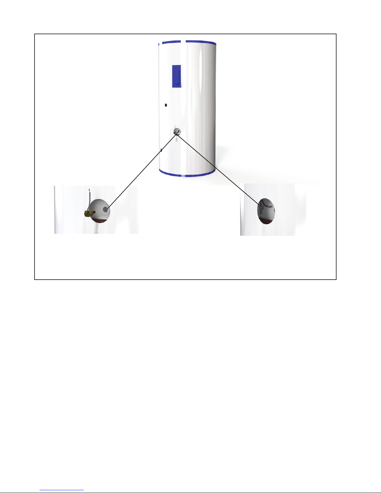
fig. 9
TANK SENSOR
THERMOWELL
pump. Continue filling the piping until water flows
from the upper hose into the basin or storage bucket.
Close the boiler drain and install the COMPONENT
#9 on the drainback reservoir.
4.14.3 STEP 3 – Run the pump to check operation
and flush impurities from the collector loop.
At this point it is recommended to run water through
the system to remove any solder flux residue or
other impurities that were introduced into the system during plumbing. Water soluble flux should
have been used when soldering pipe joints in the
collector loop to facilitate system flushing. Set the
switch on the side of the SunEarth control to the
“ON” position. Allow the pump to circulate water
through the system for 15-20 minutes. While the
pump is running check the entire collector loop for
leaks and ensure that there is adequate flow.
TANK SENSOR
JIFFY CLIP
4.14.4 STEP 4 – Check that Collectors are Draining
Back.
Turn the controller back to the ‘OFF’ position.
Allow time for the collectors and piping to drain into
the drainback reservoir. Observe the water level in
the drainback reservoir by means of the site glass,
visual flow meter or by checking with a dowel rod.
The water level in the drainback reservoir should
return to the original fill level after a few minutes.
If the water level does not return to the original fill
level, the system is not draining properly and may
freeze. If water level does not return to original
level, check format that the collectors are tilted
with riser tubes at 15° or more and that all piping is
sloped to drain at 2% or more.
4.14.5 STEP 5 - Drain the system to remove impurities.
P.16
Drain the cycled water out of the array by placing the hose attached to the lower boiler drain
Page 21
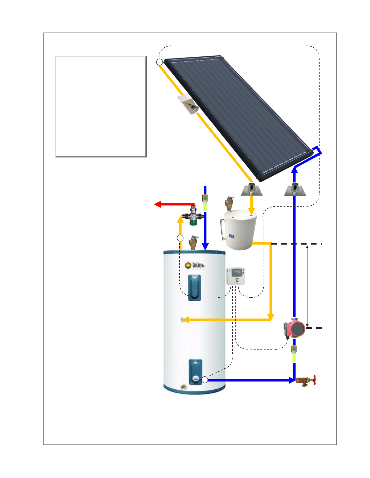
fig. 10
(1) SunEarth Solar Collector(s)
(2, 3, 4) Temperature Sensor
(5, 6, 7, 8, 22) Ball Valve
(9) Pressure Relief Valve
(10) Drain Back Tank
(11) Boiler Drain
(12) Pump
(17) Dierenal Temperature Controller
(18) Heang Element & Tank Thermostat
(19, 20) Temperature and Pressure Relief Valve
(21) Mixing Valve
HOT SUPPLY
LINE TO FIXTURES
T1
2
PIPE
INSULATION
COLD SUPPLY
LINE
20
T3
4
8
9
1
ROOF JACKS
10
17
T2
3
SINGLE TANK SCHEMATIC
48”
min.
12
22
11
P.17
Page 22
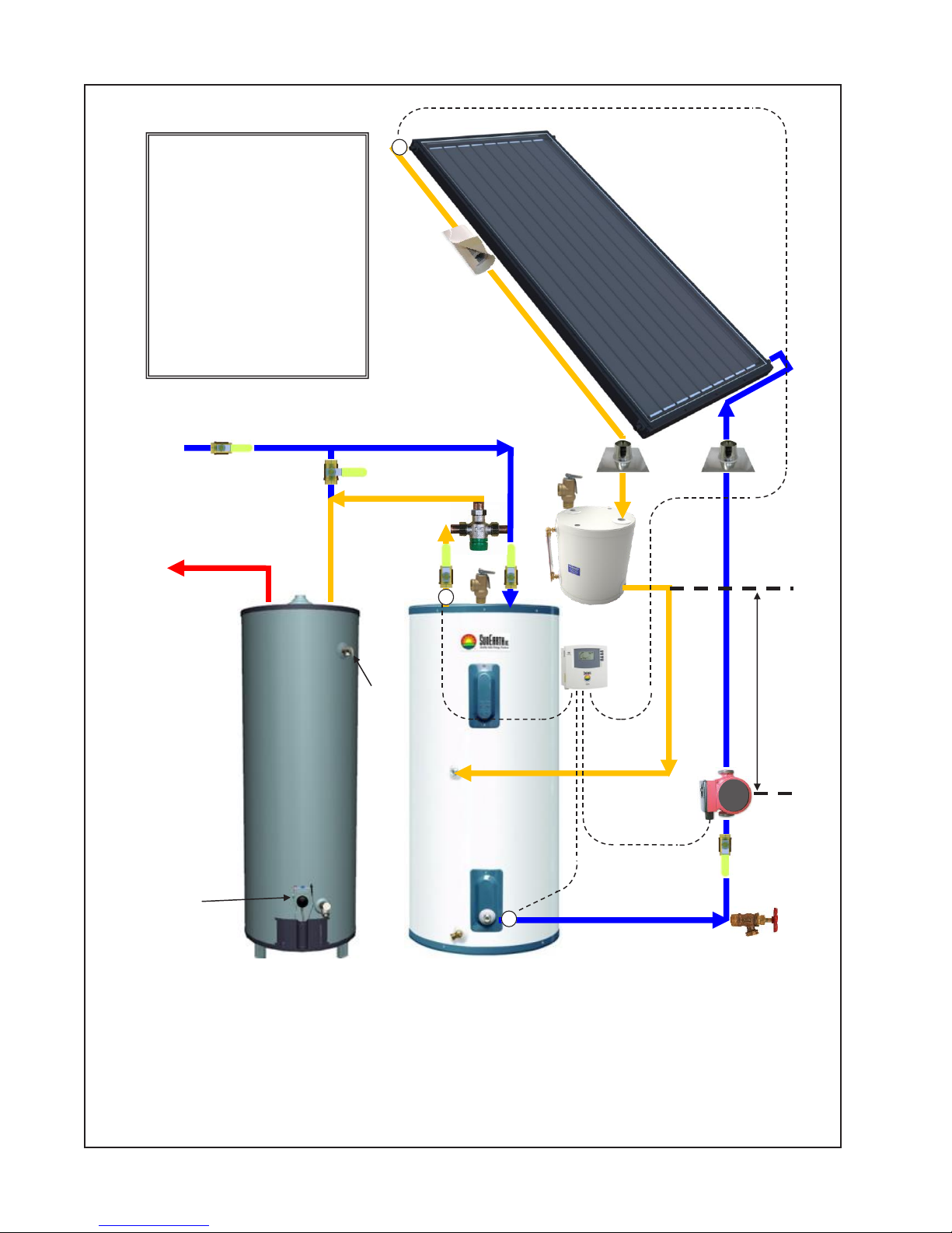
fig. 11
(1) SunEarth Solar Collector(s)
(2, 3, 4) Temperature Sensor
(5, 6, 7, 8, 22) Ball Valve
(9) Pressure Relief Valve
(10) Drain Back Tank
(11) Boiler Drain
(12) Pump
(17) Dierenal Temperature Controller
(18) Heang Element & Tank Thermostat
(19, 20) Temperature and Pressure Relief Valve
(21) Mixing Valve
COLD SUPPLY
LINE
8
HOT
SUPPLY
LINE TO
FIXTURES
T1
2
PIPE
INSULATION
5
1
9
ROOF JACKS
21
6
20
T3
4
7
10
17
18
19
T2
3
TWO TANK SCHEMATIC
48”
min.
12
22
11
P.18
Page 23
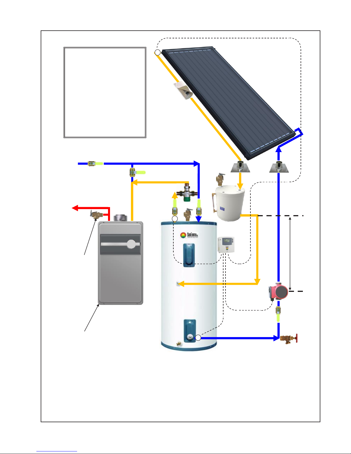
fig. 12
(1) SunEarth Solar Collector(s)
(2, 3, 4) Temperature Sensor
(5, 6, 7, 8, 22) Ball Valve
(9) Pressure Relief Valve
(10) Drain Back Tank
(11) Boiler Drain
(12) Pump
(17) Dierenal Temperature Controller
(18) Heang Element & Tank Thermostat
(19, 20) Temperature and Pressure Relief Valve
(21) Mixing Valve
(22) Tankless Water Heater
COLD SUPPLY
LINE
8
HOT
SUPPLY
LINE TO
FIXTURES
T1
2
PIPE
INSULATION
5
1
9
ROOF JACKS
21
6
20
T3
4
7
10
17
19
22
48”
min.
12
22
11
T2
3
TANKLESS BACKUP SCHEMATIC
P.19
Page 24
(COMPONENT #11) into a service drain or bucket.
Open the lower boiler drain and completely drain
the water from the system.
CAUTION: THIS WATER MAY BE
EXTREMELY HOT!
4.14.6 STEP 6 - Refill the system with water.
Repeat the STEPS 1 and 2 above to refill the collector loop with water to the correct level with deionized water.
5) SYSTEM START-UP PROCEDURES
Throughout the installation procedures outlined in
Section 4, emphasis has been placed on the proper
plumbing and wiring of the primary system components. The solder and threaded connections also
have been visually inspected for leaks and the solar
loop piping has been cleaned and charged. Having
successfully completed these tasks it is time to set
your system to run automatically.
Set the SunEarth control to the ‘ON’ position.
Listen until you can hear water flowing through the
solar loop return piping from the collector.
SINGLE TANK OPERATING
INSTRUCTIONS:
6.1 Solar Preheat:
Leave the circuit breaker on to your solar storage
tank and set the tank thermostat to the lowest acceptable temperature setting. The electric resistance
heating element will come on only when the tank
temperature falls below the thermostatic set point.
If the solar heated water entering the tank is warmer
than the thermostatic set point, the electric heating
element will not come on. If you have a water heater
timer, you may preset the timer to turn the heating
element on and off at specified times throughout the
day if desired.
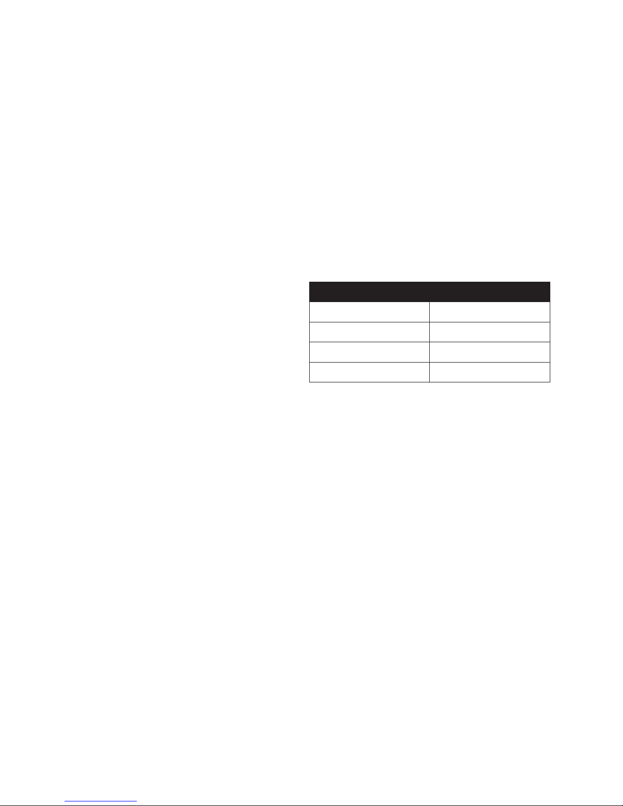
Collector Array Flowrate (GPM)
1 EP/EC-40 1.2
2 EP/EC-21 1.2
2 EP/EC-24 1.6
2 EP/EC-32 1.9
Place your ear next to the pump and listen for signs
of cavitation. Cavitation sounds like sand running
through the pump and is caused by the implosion
of small air bubbles hitting the pump impeller.
Cavitation can dramatically reduce the life of the
pump and the flow setting valve (COMPONENT
#22) should be used to eliminate this condition. If
you hear cavitation when the valve is wide open,
slowly close the valve until the sound is gone.
TABLE 4
Set the SunEarth control to the ‘AUTO’ position.
Your system is now set to run automatically whenever solar energy is available to be collected.
6) MODES OF SYSTEM OPERATION
Both single and double tank Cascade Drainback
systems are designed to accommodate two separate
modes of operation. Your system can either (1)
serve as a preheater to your conventional electric or
gas water heater or (2) be bypassed entirely and run
100% on utility power during inclement weather or
when maintenance is required.
6.2 100% Utility Power:
Leave the circuit breaker to your solar storage tank
on. In this mode of operation you must turn off the
circulation pump. To turn the pump off, change the
operational setting from automatic to “off”. Failure
to turn off the pump can quickly damage the pump
motor, shaft, bearings or impeller.
TWO TANK SYSTEM INSTRUCTIONS:
6.3 Solar Preheat:
Follow the instructions for the single tank system
for setting the thermostat, heating element or gas
fired water heater or tankless gas water heater for
automatic operation. Solar preheat mode operates
with the collectors heating the solar storage tank
and supplying this heated water into the auxiliary
tank whenever there is hot water draw. The ball
valves going to and from the solar storage tank
(Component# 6 & 7) must be open while the bypass
ball valve (Component # 5) must be closed.
6.4 100% Utility Power:
Set the thermostat for the auxiliary electric water
heater, gas fired water heater or tankless gas water
P.20
Page 25

heater to the desired hot water temperature. 100%
Utility power mode operates by supplying mains
water directly to the auxiliary heater whenever there
is hot water draw, bypassing the solar storage tank.
Follow the instructions for the single tank system
for setting the thermostat, gas or electric heater
for automatic operation. The ball valves going to
and from the solar storage tank (Component # 6
& 7) must be closed while the bypass ball valve
(Component #5) must be open.
7) SYSTEM SHUT DOWN AND ISOLATION
PROCEEDURES
Your Cascade Drainback solar water heating system
is designed so that the key components can be easily
isolated for emergency repairs or routine maintenance. By shutting a single valve you can isolate the
entire system from the pressurized cold water supply line (COMPONENT #8). In the case of a storage tank or fitting leak immediately shut this valve
and call your installation contractor for service.
The collector loop can be quickly drained if a leak
is detected or for routine maintenance. Set the
SunEarth control to the ‘OFF’ position. Next, attach
a hose to the lower boiler drain (COMPONENT
#11) and open the valve to drain the system.
CAUTION: THIS WATER MAY BE
EXTREMELY HOT!
In two tank systems the solar storage tank can be
isolated from the back-up water heater. Set the
valve handles to the 100% utility power configuration as outlined above. By closing these valves the
tank can be serviced or replaced. The operation of
the back-up water heater will not be affected.
8) SUMMER VACATION PROCEDURES
Solar water heating systems can build up very high
temperatures during summer months if there is no
daily draw on the system. If a short summer vacation is planned the best way to avoid overheating
in a drainback system is to set the SunEarth control
to the ‘OFF’ position. The pump will not circulate
during the day and the system will not “gain” any
additional heat.
For extended vacations of a month or more SunEarth
recommends that you cover the panels with a suitable opaque material. Stagnation conditions can
have an adverse effect on the internal collector
piping if the panel is left unprotected. SunEarth’s
collector warranty specifically excludes stagnation
conditions in excess of sixty days.
Remember to reset the SunEarth control to the
‘AUTO’ position upon your return and check the
system for proper operation and draining by monitoring the water levels with the pump on and off.
9) MAINTENANCE AND
TROUBLESHOOTING
The following simple procedures are intended to
optimize the performance of your Cascade Drainback
solar water heating system and also to extend the life
of the primary components.
9.1 Checking the Water Level
It is important that the drainback reservoir remains
full for proper system operation. To check the fluid
level, set the SunEarth control to the ‘OFF’ position and allow the fluid in the array to drain into the
drainback reservoir. For systems installed with an
optional flow meter or sight glass, check to see that
the fluid is not less than 1” from the top of the meter.
If your system does not have a flow meter, unscrew
the pressure relief valve (COMPONENT #9) and
dip a wooden dowel into the threaded copper fitting
to check that the fluid level is not more than 6-8”
below the valve fitting. If a small amount of fluid is
needed to bring the reservoir up to the proper level,
pour it directly into the (COMPONENT #9) fitting
port. Rewrap the thread with Teflon tape and reinstall (COMPONENT #9). You may also follow the
instructions in section 4.13 for charging the system
if more water is required.
Please remember that over time you WILL lose
some fluid in the solar loop piping. If the water
level is not properly maintained you may do irreparable damage to your circulating pump. Check your
fluid levels at least once a year.
9.2 Replacing the Anode Rod
The second most important component in your system, at least from a longevity standpoint, is often
ignored and never seen. We are referring to the sacrificial “anode rod” installed in your solar storage
tank. Typically constructed from magnesium, anode
rods are installed in “glass lined” water heaters and
storage tanks to inhibit corrosion.
As the name implies, the “sacrificial” anode rod is
consumed so that the tank lining is not. At a certain point in the process, the anode rod is no longer
P.21
Page 26

completely effective and the corrosive processes
begin to eat away at the tank’s glass lining. In time
the solar storage tank, like any other gas or electric
water heater, will begin to leak. The process is not
reversible and the tank must be replaced.
System temperatures and water quality affect the
rate at which the anode rod is consumed. In general:
the higher the average system temperature the faster
the rate of corrosion. By changing the anode rod
after the fifth year of system operation, and every
three to five years thereafter, it is possible to extend
the life of the solar storage tank. Periodic replacement of the anode rod in your solar storage tank can
significantly extend the tank life.
9.3 Flushing the Storage Tank
The solar storage tank also should be flushed annually to minimize sediment buildup on the bottom
of the tank. If you live in an area with high mineral
content in your water, flush the tank on a semi-annual basis. Disconnect the power to the solar tank at
the circuit breaker or time switch (if present) before
flushing. Set the SunEarth control to the ‘OFF’
position. In a two tank system it is not necessary to
disconnect the power to the electric water heater in
order to flush the solar tank.
Open the flush valve on the bottom of the storage tank and drain a sufficient volume of water to
eliminate the sediment. After the procedure is complete make sure the tank is completely full of water
before restoring power to the thermostat and heating
element. Set the SunEarth control to the ‘AUTO’
position.
9.4 Cleaning the Collector Glass
If you live in a dusty climate it is beneficial to wash
off the dirt that settles on the collector glass once a
month. Clean glass allows the collector to maintain
a high level of thermal performance.
9.5 Maintaining Pipe Insulation
Check the exterior pipe insulation annually and
patch or repair any exposed surfaces or degraded
areas. Repair as necessary with manufacturer’s
recommended jacket or coating or a high quality
exterior latex paint.
9.6 Glass Replacement
In the unusual instance of collector glass breakage,
the glass should be replaced immediately. This
will reduce the likelihood of water accumulating
inside the collector and deteriorating the insulation.
Contact your installation contractor to change the
glass.
9.7 Leaks
If you detect a water leak in the solar loop piping or
tank plumbing, contact your installation contractor
to service and refill the system.
9.8 Pump Not Circulating
If it’s been a sunny day and you don’t have hot
water, first make sure that the controller is set in
the automatic position. If the controller is properly
set and the pump has not been running, unplug the
line cord from the controller receptacle and plug the
pump directly into a nearby 115 VAC outlet. If the
pump does not run it may need to be replaced. If the
pump does run when plugged directly into the wall
outlet, the problem may be located in the controller
or one of the temperature sensors. Contact your
installation contractor for service.
9.9 Night Time Heat Loss
If you have a full tank of hot water before bed and
the solar storage tank is cold in the morning make
sure that the circulating pump is not running at
night. If the pump is running and the controller displays questionable temperatures at the collector or
tank (i.e. 180ºF tank and 45ºF collector), check both
sensors using a resistance meter to see if they are
correctly calibrated. If you find a defective sensor
replace it immediately.
9.10 Auxiliary Electric Element not Operating
If the weather is poor and the auxiliary heating element will not fire, the bright red reset button on the
thermostat may have to be depressed to be reset.
Single tank systems have one heating element and
thermostat. Double tank systems with conventional
electric water heaters have two heating elements and
thermostats.
DANGER: NEVER REMOVE THE
PROTECTIVE ACCESS PLATE ON THE
EXTERIOR OF THE SOLAR STORAGE
TANK OR CONVENTIONAL WATER
HEATER WITHOUT DISCONNECTING THE
230 VAC POWER SUPPLY AT THE CIRCUIT
BREAKER.
Installation Manual
P.22
Page 27

After the circuit breaker has been turned off, remove
the access plate on the storage tank or water heater
and depress the red reset button on the thermostat.
If it clicks when depressed the heating element
should fire immediately when you reconnect the
circuit breaker. It the reset button does not click and
you do not have hot water after one hour, the heating
element or thermostat may be defective. Contact
your installation contractor for service.
9. Pressure Relief Valve(PRV): Will discharge
heat transfer fluid (water) from the collector closed
loop at the PRV pressure setting, (typically 30 –
150 PSI). Under normal operating conditions, the
pressure relief valve will not discharge fluid. If
this valve opens and water is expelled contact your
contractor immediately. This valve also can be
manually opened to assist filling or draining the collector loop.
In two tank systems the conventional electric water
heater will be wired for electrical back-up. The
solar tank will serve solely as a storage tank and will
not be wired.
10) CASCADE DRAINBACK SYSTEM
COMPONENT PARTS
See Figures 10, 11 and 12 for the location of the
specific component numbered below.
1. SunEarth Solar Collector(s): Absorbs the sun’s
heat energy and transfers this heat to the heat
exchange fluid (water) circulating through the collector.
2. Collector Sensor (T1): Wired to the control.
Works in conjunction with the tank sensor to automatically turn your circulating pump on and off at
preset temperature differentials.
3. Tank Sensor (T2): Wired to your controller.
Works in conjunction with the collector sensor to
turn your circulating pump on and off at preset temperature differentials.
The PRV protects the collector and all components
in the collector loop from pressures in excess of the
PRV pressure setting.
WARNING: THE PRESSURE RELIEF VALVE
SETTING MUST NOT BE HIGHER THAN
THE MAXIMUM WORKING PRESSURE OF
THE COMPONENTS IN THE COLLECTOR
LOOP.
10. Drainback Reservoir: An insulated storage reservoir that holds the collector and solar loop piping
heat exchange fluid (water) when the circulating
pump is off.
11. Drain/Purge Valve: Used to charge and drain
the solar loop piping.
12. Circulating Pump: Circulates water through the
collector and solar loop piping.
17. Differential Temperature Controller:
Automatically turns the circulating pump on and
off when there is sufficient heat to be gained in the
solar collector.
4. Tank Outlet Sensor (T3) - Optional: Wired to
your controller, this sensor shows the temperature
of the hot water leaving the solar storage tank. This
sensor is for information purposes only, it does not
affect the control of the system.
5, 6, 7. Solar Tank Bypass Valve Assembly: For
two tank systems only. Assembly of three ball
valves allows the solar tank to be completely isolated and bypassed in the case of tank failure. When
the solar tank is bypassed, water will be heated by
the auxiliary heater only. Solar bypass valve assembly may also be a combination of two 3-way valves
or a single 4-port single action bypass valve.
8. Mains Supply Line Isolation Valve: When open
allows potable water to fill the solar storage tank or
back-up water heater. When closed isolates the solar
storage tank and back-up water heater from the pressurized city cold water supply line.
P.23
18. Heating Element & Tank Thermostat: The auxiliary water heater thermostat controls the temperature setting of the auxiliary heating element.
19, 20. Temperature and Pressure Relief Valve:
Universally required by the plumbing code on water
heaters. Will automatically release and dump water
at either 150 PSI of pressure or 210° F in temperature.
21. Mixing Valve: Automatically blends hot water
from the solar storage tank with incoming city cold
water to an acceptable set point. A mixing valve
must be installed on every Cascade Drainback
solar water heating system. The mixing valve may
include and integral check valve to prevent backflow of mixed or hot water into the cold water feed
line. When the mixing valve does not include an
integral check valve, an external check valve should
be placed on the cold feed to the mixing valve. In
Page 28

two tank systems the mixing valve may be located;
either at the outlet to the solar storage tank; or at the
outlet to the auxiliary heater.
22. Pump Throttling Valve: May be partially closed
to reduce the flow rate and prevent pump cavitation.
11) ESTIMATED COMPONENT LIFE
You can expect a long useful life from the primary
components in your Cascade Drainback solar water
heating system by adhering to the routine service
and maintenance tips provided above.
The SunEarth solar collector and drainback reservoir have a design life of twenty-five to thirty years.
The solar storage tank should last twelve to twenty
years in most water quality areas provided the anode
rod is periodically replaced. The circulating pump
and differential control should last 10 to 15 years
before needing to be replaced. Like EPA mileage
estimates for automobiles, these component design
lives represent average figures for drainback system
components installed in the United States. The life
of your components may vary.
tank not less than 75% full. When the system is
circulating (pump running); the water level in the
drainback tank should be not less than 25% full.
The drainback tank should never be pumped dry in
normal operation as this may result in damage to the
circulator pump.
Installation Manual
To obtain warranty service, please see the completed Appendix on the back of this manual with
your installation contractor contact information or
contact SunEarth Inc. for the name of an authorized
service agent near you.
12) SYSTEM OPERATING PARAMETERS
12.1 Collector Loop Pressure
The pressure in the solar collector loop should be
within 0 – 20 PSIG.
12.2 Circulation Flow Rate
The flow rate in the collector loop should be 0.5 –
4 GPM when the pump first comes on (filling the
collector loop). Once the collector loop is full and
water starts to siphon down the return piping the
flow rate will normally increase and should be 0.8 –
5 GPM with the system circulating.
12.3 Temperature Differential
The temperature difference between the collector
outlet sensor (T1) and the solar tank sensor (T2)
should be 4 ºF – 30ºF when the system is circulating.
12.4 Fluid Level
The water level when the system is not circulating (pump stopped) should such that the drainback
P.24
Page 29

P.25
Page 30

P.26
Page 31
APPENDIX A.
CASCADE DRAINBACK OG-300 APPROVED COMPONENTS
Solar Collectors – SunEarth Liquid Flat Plate Collectors
Make
Series
Model Numbers
SunEarth
Empire, Paint
EP-21
EP-24 EP-24-0.75 EP-24-1.5
EP-32 EP-32-0.75 EP-32-1.5
EP-40 EP-40-0.75 EP-40-1.5
SunEarth
Empire, Chrome
EC-21
EC-24 EC-24-0.75 EC-24-1.5
EC-32 EC-24-0.75 EC-32-1.5
EC-40 EC-40-0.75 EC-40-1.5
SunEarth
SunBelt
SB-24-0.75
SB-32-0.75
SB-40-0.75
SunEarth
Imperial, Chrome
IC-32
IC-40
SunEarth
Imperial, Selective
IS-32
IS-40
SunEarth
ThermoRay
TRB-32
TRB-40
Collector Mounting Hardware
Make
Series
SunEarth
SolarStrut
RexRack
Flush Mount Kit
Universal Tilt Kit
Landscape Rack
Install mounting hardware per SunEarth manuals, standard residential drawings, and/or plan sets.
Storage Tank with Integral Double Wall Heat Exchanger
Make
Series
Model Numbers
SunEarth
SunEarth
SU80HE-1
*
SU65HE-1
*
SU120HE-1*
Rheem
Solaraide
81V80HE-1
*
81V80HE-T
Ϯ
81V120HE-1* 81V120HE-T
Ϯ
81V65HE-1
*
Ruud
Solar Servant
RSPE80HE-1* RSPE80HE-T
Ϯ
RSPE120HE-1* REPE120HE-T
Ϯ
RSPE65HE-1*
*
Includes auxiliary 4.5 kW heating element, suitable for one or two tank systems.
Ϯ
Does not include auxiliary heating element, suitable for two tank systems only.
P.27
Page 32

Differential Temperature Controller
Make
Series
Model Numbers
SunEarth
SETR0301U
SETR0502U
SETR0603mcU
SETR A501 T
SETR A502 TT
SETR A503 TTR
Steca
TR0301U
TR0502U
TR0603mcU
TR A501 T
TR A502 TT
TR A503 TTR
Independent
Energy
Goldline
GL-30-X216
GL-30-X217
or Approved Equal
Drainback Reservoir
Make
Series
Model Numbers
SunEarth
CopperStor
DB-2.5 DB-5.0
DB-7.5 DB-10
SolarH2OT
DBT
DBT 10 SS DBT 15 SS
DBT 20 SS
Rheem
Energy Miser
81VP6S 81VP10S
81VP15S 81VP20S
or Approved Equal
Circulator Pumps
The circulator pump shall be a wet rotor small circulator with a cast iron, stainless steel,
brass or polymer body and a metal or polymer impeller. The pump motor shall be
induction or permanent magnet ECM driven. The pump shall be rated for: maximum fluid
temperatures of no less than 180
o
F and pressures of no less than 125 PSI. The maximum
rated amperage shall be no more than 1.5 Amps and the maximum rated power draw shall
be no more than 135 Watts.
Thermostatic Mixing Valve
The thermostatic mixing valve shall have a bronze, brass or stainless steel body with a
rated maximum working temperature no less than 200
o
F and a rated maximum working
pressure no less than 125psi. The range of temperature set points shall be at least 18ºF
(10ºC) and shall include a set point of 120ºF (50ºC). The Thermostatic Mixing valve shall
be third party listed and certified to one of the following ASSE standards: ASSE 1016;
ASSE 1017; ASSE 1070.
P.28
Page 33

Ball Valves
Ball valves shall be of bronze, brass or stainless steel construction. Maximum working
temperature shall be no less than 200
than 125 psi.
o
F and maximum working pressure shall be no less
Three-Way Valves (Optional)
Three-Way valves shall be of bronze, brass or stainless steel construction. Maximum
working temperature shall be no less than 200
no less than 125 psi.
o
F and maximum working pressure shall be
Boiler Drains (A.K.A. Charge Valves; Fill Valves; Drain Valves)
Boiler Drains shall be of bronze, brass or stainless steel construction. Maximum working
temperature shall be no less than 200
than 125 psi.
o
F and maximum working pressure shall be no less
Pressure Relief Valve
The pressure relief valve shall be of bronze, brass or stainless steel construction with a
pressure setting between 30psi and 150psi. The pressure relief valve shall be set to
discharge at a pressure below the maximum design pressure of all other components in the
collector loop.
Thermometers (Optional)
Thermometers shall be dial or scale type and shall have a metallic body and casing and a
glass lens. The range of measurement shall be not less than 30
accuracy of +/- 2%. An electronic temperature sensing system may be used in place of
dial or scale thermometers (see below).
o
F to 200oF with an
Temperature Sensors (Electronic)
An electronic temperature sensing system may be used in place of dial or scale
thermometers. Temperature sensors shall be shall be of metallic construction and have a
maximum temperature rating not less than 200
o
F. Temperature reading may be via digital
readout, LCD screen, internet or other electronic device. The temperatures may be read at
the differential controller screen. The range of measurement shall be not less than 30
o
200
F with an accuracy of +/- 2%.
Sensor Wire:
Sensor wire for temperature sensors or other electronic sensors must be no less than
18/2 AWG. Sensor wire must be insulated; in locations where the sensor wire is
exposed to the elements it must be UV resistant and rated for outdoor use.
o
F to
P.29
Page 34

PUMP SELECTION GUIDELINES
Drainback systems operate under two different sets of conditions. The filling condition
occurs when the controller activates the pump and water starts to fill the collectors. In
the filling condition the pump has to overcome the system’s static head (or lift) and
friction head loss. The static head is the vertical height difference measured from the
highest point in the system to the bottom of the drainback reservoir (in feet). During the
filling condition the flow rate may be less than the design flow rate of the system, but
should be at least 0.5 GPM in order to fill the collectors and flush all the air down the
return pipe into the drainback tank.
Once the collectors and return pipe between the collectors and drainback tanks are full of
water the return line will start siphoning, this counterbalances the static head. The system
is now in the running condition and the pump is only required to overcome the system
friction head loss. With the elimination of the static head, the pump will start to circulate
the fluid at a higher flow rate (unless a variable speed pump and controller are used). In
the running condition the flow rate will often be higher than the design flow rate; this is
acceptable provided the fluid velocity remains below 4 ft /second. Above 4 ft /s the
collector life may be reduced by erosion corrosion. A flow rate of more than the listed
maximum through any collector should be avoided.
The system’s static head is the most significant parameter when selecting the pump. The
pump selected must have a shut off head of at least the system static head plus four feet
safety factor. The larger the static head the bigger the pump required and the greater the
risk of excessive flow once the system starts siphoning. To reduce the static head in
buildings with multiple floors, the drainback tank should be located on the top floor, as
close to the ceiling as possible. Pumps with a “steep” pump curve are also preferred, as
these will operate over a smaller range of flows at different heads
.
Cascade drainback systems are not open to atmosphere (capped and sealed on
installation). Provided the water used to fill the system is free of salts or other
contaminants, a cast iron pump may be used. However, it is common for some rusting of
the pump body to occur until the oxygen in the water is depleted. This rust will often
circulate through the collector loop, making the fluid an unsightly brown color which will
be visible in the sight glass or flow meter. If this brown water is not acceptable, or if the
fluid used in the collector loop contains corrosive elements, a pump with a bronze or
stainless steel body should be used.
The following pump selection tables are appropriate for all OG-300 Cascade Drainback
systems, the pump selection is a based on the lift required from the drainback tank to the
highest point in the system (the system static head).
P.30
Page 35
Low Lift Systems: 5ft - 10ft Static Head
SYSTEM PARAMETERS PUMPS
Grundfos Taco Wilo
Static Lift Head 5 to 10 ft
Cast Iron
UP 15-100 009-F5 Star 32F
Minimum Fill
Flow Rate 0.5 gpm UPS 15-58 F* 008F6 Star 16F
Design Flow
Rate
0.83 - 2.08
gpm
Stainless
Steel
UP 15-100 SU7
Heat Exchange
Tank 80 or 120 gal UPS 15-55 SF*
1/2" Type L
Supply Pipe up to 100 ft
Bronze
UP 26-96 BF 009-BF5 Star 32BF
3/4" Type L
Return Pipe up to 100 ft
*REMOVE INTEGRAL CHECK VALVE FROM PUMP IF INCLUDED
Medium Lift Systems: 10ft - 30ft Static Head
SYSTEM PARAMETERS PUMPS
Grundfos Taco Wilo
Static Lift Head 10 to 30 ft
Cast Iron
UP 15-100 009-F5 Star 32F
Minimum Fill
Flow Rate 0.5 gpm
Design Flow
Rate
0.83 - 2.08
gpm
Stainless
Steel
UP 15-100 SU7
Heat Exchange
Tank 80 or 120 gal
1/2" Type L
Supply Pipe up to 100 ft
Bronze
UP 26-96 BF 009-BF5 Star 32 BF
3/4" Type L
Return Pipe up to 100 ft
High Lift Systems: Over 30ft Static Head
For systems with static head in excess of 30ft no single small circulator pump will be able
to fill the system. In these cases it may be necessary to stack two pumps in series. A
combination of two of the approved pumps in the tables above should be used. The total
pumping head available will be the sum of the two pumps’ shut off heads. When pumps
are stacked in this way, the controller should be set to turn on both pumps at once, but
one of the pumps is controlled through a time delay relay. Both pumps are turned on to
fill the system, after 5 minutes one of the pumps is turned off and the system continues to
operate with just one pump in the running condition.
008-BF/BC6 Star 16BF
P.31
Page 36

CASCADE DRAINBACK OG-300 SYSTEM MODEL NOS.
Single Tank Electric Auxiliary Systems Two Tank Electric Auxiliary Systems
EPRD-40-80 EPRD-40-80-2
ECRD-40-80 ECRD-40-80-2
EPRD-42-80 EPRD-42-80-2
EPRD-48-80 EPRD-48-80-2
ECRD-48-80 ECRD-48-80-2
EPRD-64-80 EPRD-64-80-2
ECRD-64-80 ECRD-64-80-2
EPRD40-120
EPRD64-120
EPRD80-120
ECRD40-120
ECRD64-120
ECRD80-120
Tank Type Gas Water Heater Auxiliary Tankless Gas Water Heater Auxiliary Systems
EPRD-40-802G ECRD-32-80-TLG
ECRD-40-80-2G ECRD-40-80-TLG
EPRD-42-80-2G ECRD-48-80-TLG
EPRD-48-80-2G ECRD-64-80-TLG
ECRD-48-80-2G EPRD-32-80-TLG
EPRD-64-80-2G EPRD-48-80-TLG
ECRD-64-80-2G EPRD-64-80-TLG
EPRD-64-80-75G ECRD-32-120-TLG
EPRD-64-80-100G ECRD-40-120-TLG
ECRD-32-80-2G ECRD-48-120-TLG
EPRD-32-80-2G ECRD-64-120-TLG
ECRD-32-120-2G EPRD-32-120-TLG
ECRD-40-120-2G EPRD-40-120-TLG
ECRD-64-120-2G EPRD-48-120-TLG
EPRD-32-120-2G EPRD-64-120-TLG
EPRD-40-120-2G EPRD-80-120-TLG
EPRD-48-120-2G ECRD-80-120-TLG
EPRD-64-120-2G
EPRD-80-120-2G
EXAMPLE: EPRD48-80-2G
Empire Series Collector, Moderately Selective Painted Absorber Coating, Ruud/Rheem Heat Exchange
Tank, Drainback Tank, 2 each Empire EP-24 3’ X 8’ Collectors (48 ft2), 80 Gallon Tank.
- 2: Two tank system with back-up electric storage water heater
-2G: Two tank system with back-up gas water heater
-TLG: Tankless gas back-up
ECRD48-80-2G: Designates SunEarth Empire series collector with black chrome over nickel absorber
coating.
APPENDIX C
P.32
Page 37
Appendix C
CASCADE DRAINBACK SYSTEM & COMPONENT LABELS
Labels containing the text below shall be attached to the appropriate valves on all SRCC
OG-300 certified systems.
FLUID IDENTIFICATION:
THE HEAT TRANSFER FLUID USED IN THIS SYSTEM IS WATER. NO OTHER
FLUID SHALL BE USED THAT WOULD CHANGE THE ORIGINAL
CLASSIFICATION OF THIS SYSTEM.
BE EXTREMELY CARFUL WHEN DRAINING THIS FLUID. IT MAY BE
DISCHARGED AT A VERY HIGH TEMPERATURE AND PRESSURE.
HEAT EXCHANGER
THE HEAT EXCHANGER USED IN THIS SYSTEM IS DOUBLE WALL VENTED
TO ATMOSPHERE. THE HEAT EXCHANGER IS INTEGRAL TO THE SOLAR
STORAGE TANK.
FREEZE LABEL:
THE CASCADE DRAINBACK SYSTEM IS PROTECTED FROM FREEZING BY
AUTOMATICALLY DRAINING THE SOLAR COLLECTORS AND EXPOSED
PIPING WHENEVER THE CIRCULATION PUMP SHUTS OFF. WHEN PROPERLY
INSTALLED AND OPERATED THE SYSTEM IS PROTECTED TO
TEMPERATURES AS LOW AS -50 F.
BOILER DRAIN NO. 11 – SYSTEM FILL & DRAIN VALVE
VALVE 11 IS NORMALLY CLOSED. WHEN OPENED IN CONJUNTION WITH
PRV (COMPONENT # 9) IT IS USED TO CHARGE AND DRAIN THE SOLAR
COLLECTOR LOOP PIPING.
THE HEAT TRANSFER FLUID USED IN THIS SYSTEM IS WATER. NO OTHER
FLUID SHALL BE USED THAT WOULD CHANGE THE ORIGINAL
CLASSIFICATION OF THIS SYSTEM. UNAUTHORIZED ALTERATIONS TO
THIS SYSTEM COULD RESULT IN A HAZARDOUS HEALTH CONDITION.
BE EXTREMELY CARFUL WHEN DRAINING THIS FLUID. IT MAY BE
DISCHARGED AT A VERY HIGH TEMPERATURE AND/OR PRESSURE.
VALVE NO. 8 - COLD WATER SUPPLY ISOLATION VALVE
THIS VALVE IS NORMALLY OPEN AND ALLOWS POTABLE WATER TO FILL
THE SOLAR STORAGE TANK. WHEN CLOSED THE SOLAR STORAGE TANK IS
ISOLATED FROM THE PRESSURIZED CITY COLD WATER SUPPLY LINE
PIPING.
P.33
Page 38
VALVE NO. 22
VALVE 22 IS NORMALLY OPEN. IT MAY NECESSARY TO PARTIALLY CLOSE
VALVE 22 TO PROTECT THE PUMP FROM CAVITATION BY REDUCING FLOW
RATES IN THE COLLECTOR LOOP.
PRESSURE RELIEF VALVE (COMPONENT #9)
THE PRV WILL AUTOMATICALLY OPEN AND DISCHARGE FLUID OR AIR IN
THE EVENT OF THE COLLECTOR LOOP PRESSURE EXCEEDING THE
MAXIMUM WORKING PRESSURE OF THE SYSTEM.
WHEN FILLING OR DRAINING THE SYSTEM THROUGH BD, THE PRV IS
MANUALLY OPENED OR REMOVED FROM THE COLLECTOR LOOP IN ORDER
TO ALLOW AIR TO FLOW IN OR OUT OF THE COLLECTOR LOOP.
VALVE NO. 7 – COLD FEED TO SOLAR TANK ISOLATION VALVE
THIS VALVE IS NORMALLY OPEN. WHEN CLOSED IN CONJUNCTION WITH
VALVE NO. 6 IT WILL ISOLATE THE SOLAR STORAGE TANK FROM THE
ADDITIONAL TWO TANK SYSTEM VALVES
POTABLE WATER SYSTEM.
VALVE NO. 6 – HOT OUTLET FROM SOLAR TANK ISOLATION VALVE
THIS VALVE IS NORMALLY OPEN. WHEN CLOSED IN CONJUNCTION WITH
VALVE NO. 7 IT WILL ISOLATE THE SOLAR STORAGE TANK FROM THE
POTABLE WATER SYSTEM.
VALVE NO. 5 – SOLAR TANK BYPASS VALVE
THIS VALVE IS NORMALLY CLOSED. WHEN OPENED IN CONJUNCTION
WITH CLOSING VALVES NO. 6 & 7 IT WILL ALLOW COLD WATER TO
BYPASS THE SOLAR SYSTEM AND FEED DIRECTLY INTO THE AUXILLIARY
WATER HEATER.
P.34
Page 39
Installation Manual
Effective 01/17/11 Protecting Our Environment – Since 1978
www.sunearthinc.com
TEN-YEAR LIMITED PRODUCT WARRANTY
This warranty only applies to the following SunEarth products (hereinafter SunEarth Products):
COLLECTORS: Empire, Imperial, SunBelt, SunWise, and Custom Collectors
ABSORBERS: SunBurst and Custom Absorber Plates used in any glazed application
ICS AND DRAINBACK: CopperHeart ICS, CopperHeart Tanks, and CopperStor DrainBack Tanks
Under conditions of normal use and service the above SunEarth Products are warranted to the original, or
subsequent users, for a period of 10 years from the date of sale to be free of defects in material and
workmanship pursuant to the exclusions detailed in this written warranty statement. SunEarth's liability for
these products shall be limited to repairing or replacing at SunEarth's option, without charge, F.O.B.
SunEarth's factory or an authorized SunEarth distributor or service center. SunEarth will not be liable for
any costs of transportation, inspection, removal, reinstallation, or any other labor or freight charges that
may arise in connection wit
h a warranty claim, except as expressly set forth in this warranty.
The use of ANY of the above SunEarth Products for pool or spa heating is NOT covered by this
warranty, UNLESS the pool or spa water is isolated from the above SunEarth Products through the use of a
heat exchanger.
FIELD LABOR
Field labor to repair or replace any defective SunEarth Product is reimbursable as follows:
Year 1
$100/collector
Year 2 ~ 5
$75/collector
Year 6 ~ 10
$50/collector
FREIGHT AND SHIPPING EXPENSES
In the event of a valid warranty claim approved by SunEarth, SunEarth will pay for freight and shipping
expenses as follows:
Year 1 of Warranty: SunEarth will pay the freight and shipping costs for the new or repaired SunEarth
Product between SunEarth and the nearest local distributor, dealer, authorized service center, city, or
shipping terminal.
After Year 1 of Warranty: Freight and shipping costs are the responsibility of the owner.
THIS WARRANTY DOES NOT APPLY
This warranty does not apply to the following: (1) conditions resulting from a failed component or part
that is not part of the above listed SunEarth Products; (2) to damage caused by freezing conditions; (3) to
conditions resulting from misuse, abuse, neglect, accident, or alteration; (4) to cosmetic discoloration of the
collector framewall, absorber plate, or glazing over time; (5) to glass breakage; (6) to conditions resulting
from the introduction of harmful chemicals, caustic fluids, or liquids deleterious to copper tubing, including
improperly applied o
r maintained heat transfer fluids or chlorinated pool or spa water; (7) to SunEarth
Products in which heat transfer fluids other than potable water or propylene glycol (DowFrost HD
Page 40
Effective 01/17/11 Protecting Our Environment – Since 1978
www.sunearthinc.com
recommended) was used; (8) to propylene glycol pH levels above 10 or below 8; (9) to periods of
stagnation in excess of 30 days; (10) to excessive pressure; (11) to erosion corrosion of the copper tubing
resulting from excessive flow rates; (12) to improper plumbing configurations that do not conform to
SunEarth’s manifolding requirement
s; (13) to clouding or condensation naturally resulting from temporary
intrusions of moisture into the collector; (14) to conditions resulting from floods, earthquakes, winds, fire,
lightning, or circumstances beyond SunEarth's control; (15) to damage caused by installation methods,
including mounting, that do not conform to relevant national, state or local codes and ordinances, good
industry practices, or to current applicable SunEarth manuals, diagr
ams, technical bulletins, or written
installation instructions; (16) or to applications other than medium temperature (110 - 160F) domestic water
heating.
If one of the above SunEarth Products is purchased outside the United States certain conditions of this
warranty may NOT apply. Please contact your local SunEarth distributor or dealer for details.
LIMITED WARRANTY
EXCEPT AS EXPRESSLY PROVIDED IN THIS WARRANTY, THE ABOVE SUNEARTH
PRODUCTS ARE PROVIDED WIT
HOUT WARRANTY OF ANY KIND, EITHER EXPRESS OR
IMPLIED, INCLUDING, BUT NOT LIMITED TO, THE IMPLIED WARRANTIES OF
MERCHANTABILITY AND FITNESS FOR A PARTICULAR PURPOSE OR ANY WARRANTY
OR NON-INFRINGEMENT. SOME STATES DO NOT ALLOW THE EXCLUSION OF IMPLIED
WARRANTIES, SO THE ABOVE EXCLUSION MAY NOT APPLY TO YOU.
LIMITATIONS OF REMEDIES
IN NO EVENT SHALL SUNEARTH BE LIABLE FOR ANY DAMAGES FOR LOST PROFITS,
LOST SAVINGS OR OTHER INCIDENTAL OR CONSEQUENTIAL DAMAGES, AR
ISING OUT
OF THE USE OR INABILITY TO USE THE ABOVE SUNEARTH PRODUCTS, OR FOR ANY
CLAIM BY A THIRD PARTY. SOME STATES DO NOT ALLOW THE LIMITATION OR
EXCLUSION OF LIABILITY FOR INCIDENTAL OR CONSEQUENTIAL DAMAGES, SO THE
ABOVE LIMITATION MAY NOT APPLY TO YOU.
EXCLUSIVE AGREEMENT
THIS WARRANTY CONSTITUTES THE ENTIRE, COMPLETE, FINAL, AND EXCLUSIVE
AGREEMENT FOR THE SUNEARTH PRODUCTS LISTED ABOVE. THIS WARRANTY
SUPERSEDES ANY PROPOSAL, AGREEMENT, OR REPSRESEN
TATION, OR ANY OTHER
COMMUNICATION, EITHER WRITTEN OR ORAL, MADE BETWEEN SUNEARTH AND
SUNEARTH’S DISTRIBUTORS OR DEALERS, OR BETWEEN SUNEARTH AND THE END
CONSUMER.
TO MAKE A CLAIM
To obtain service under this warranty, the product in question must be returned to the distributor or dealer
of SunEarth products nearest you, or an authorized SunEarth service center. Each claim must be
accompanied by documentation providing the following:
1) Owner’s name, address, email address, and phone number
2) Installation contractor’s name, email address, and phone number
3) Original sales receipt
4) Product model and serial number(s)
5) Date of installation
6) Date of failure
7) Reason for failure
8) Pictures of the suspected manufacturing defect – digital pictures of the suspected manufacturing defect
also need to be submitted
If you have any warranty questions, contact your installation contractor or SunEarth at (909) 434 -3100.
Page 41

Contractor/Installer Information
Service & Warranty Information
Name:
Address:
Phone:
Email:
System Info
Model NO.
Date Puchased:
Date Installed:
Product Serial:
Company:
Comments:
For Service and Repair Contact:
APPENDIX H
P.37
Page 42

8425 Almeria Avenue • Fontana, CA 92335
Phone: (909) 434-3100 • Fax: (909) 434-3101
email: [email protected] • www.sunearthinc.com
Revised 9-6-13
 Loading...