

Page 1

Installation, Operation
& Maintenance Manual
Sundyne Pumps
Model:
LMV-801S
`
SA-07-11-92, Rev Orig
Oct 2015
Page 2

Copyright
All rights reserved. Nopart of this publication may be reproduced, stored in a retrieval system or transmitted in any form or by any
means, electronic, mechanical, photocopying, recording or otherwise without the prior permission of Sundyne LLC.
© 2015 Sundyne LLC
Warranty
Sundyne LLC warrants to Buyer for a period of twelve (12) months from the date of being placed in service (but not to exceed
eighteen (18) months after the date of shipment) that the equipment at the time of shipment will be free from defects of design,
material and workmanship. If any defects or malperformance occur during the warranty period, Sundyne’s sole obligation shall be
limited to alteration, repair or replacement at Sundyne’s expense, F.O.B. Factory, of parts or equipment, which upon return to
Sundyne and upon Sundyne’s examination prove to be defective. Equipment and accessories not manufactured by Sundyne are
warranted only to the extent of and by the original manufacturers’ warranty. Sundyne shall not be liable for damage or wear to
equipment caused by abnormal conditions, vibration, failure to properly prime or to operate equipment without flow or caused by
corrosives, abrasives or foreign objects. THE FOREGOING WARRANTY IS EXCLUSIVE AND IN LIEU OF ALL OTHER
WARRANTIES, WHETHER EXPRESSED OR IMPLIED INCLUDING ANY WARRANTY OF MERCHANTABILITY OR FITNESS
FOR ANY PARTICULAR PURPOSE. In no event shall Sundyne be liable for consequential or incidental damages
http://www.sundyne.com
Page 3

EUROPEAN UNION MACHINERY DIRECTIVE
(CE Mark System)
(where applicable)
This document incorporates information relevant to the Machinery Directive 2006/42/EC. It should be
read prior to the use of any of our equipment. Individual maintenance manuals which also conform to the
EU Directive should be read when dealing with specific models.
EUROPEAN UNION ATEX DIRECTIVE
This document incorporates information relevant to the ATEX Directive 94/9/EC (Directive on equipment and
protective systems intended for use in potentially explosive atmospheres). It should be read prior to the use
of any our equipment.
Compliance to the Directive is based on Atmospheres having pressures ranging from 0.8 to 1.1 bar and
temperatures ranging from –20 C to + 60 C.
As indicated in the ATEX Directive 94/9/EC, It is the responsibility of the user of the pump to indicate to HMD
Sealless Pumps the Zone and Corresponding group (Dust or Gas) that the pump is to be installed within.
Service
Americas
Sundyne LLC Tel: +1-303-425-0800
Web: www.sundyne.com
Europe
HMD Sealless Pumps Ltd Tel: +44 (0) 1323 452000
Hampden Park Industrial Estate, Fax: +44 (0) 1323 503369
Eastbourne Email: [email protected]
East Sussex Web: www.sundyne.com
BN22 9AN
England
Customer Service 24 Hour 07966 525269
Sundyne LLC i http://www.sundyne.com
SA-07-11-92, Rev Orig October 2015
Page 4
Sundyne LLC ii http://www.sundyne.com
SA-07-11-92, Rev Orig October 2015
Page 5

Revisions
October 2015 Original Release
Sundyne LLC iii http://www.sundyne.com
SA-07-11-92, Rev Orig October 2015
Page 6

Contents
Contents.............................................iv
INTRODUCTION..................................1
Sundyne Centrifugal Pumps...........................1
Text Symbols....................................................2
Equivalent Terms...........................................3
Units...............................................................3
Equipment and Safety Precautions................4
Wearing Personal Protective Equipment.......4
Lifting .............................................................4
Using Forklifts ................................................4
Ensuring Electrical Safety..............................5
Testing Equipment.........................................5
Magnets.........................................................5
Using Chemicals............................................5
Protection from Falling...................................5
Preventative Machine Guards .......................5
Pre-Commission Checklist..............................6
Familiarizing Yourself with the Pump ............6
Driver Instructions..........................................6
Verifying Auxiliaries .......................................6
Checking Driver Rotation...............................6
Piping Connections........................................6
General..............................................................7
Application or Use..........................................7
Net Positive Suction Head (NPSH).............14
Discharge Pipework.....................................15
Protection Systems .......................................16
Power Control Monitor (PCM) .....................16
Temperature Sensor....................................16
Differential Pressure Switches ....................16
Liquid Sensing Probe ..................................17
Secondary Containment or Control.............17
VapourView®...............................................17
Precautions ....................................................19
Installation Considerations ..........................19
Commissioning..............................................21
General........................................................21
Venting ........................................................21
Direction of Rotation....................................21
START UP.........................................22
Start-Up Procedures......................................22
Run-In..........................................................22
Start Up .......................................................22
Operating Guidelines ....................................23
Precautions..................................................23
Controlling the Pump During Startup..........26
Single Operation..........................................26
Parallel Operation........................................26
Temperature Classification - (ATEX Directive
94/9/EC).............................................................7
INSTALLATION...................................9
Inspection .........................................................9
Storing Your Pump Short-Term......................9
Storing Your Pump Long-Term ......................9
Installation Guidelines...................................10
Location .......................................................10
Foundations.................................................10
Electrical Installation & Grounding..............11
Suction and Discharge Piping ......................12
Pitfalls to Avoid On Suction Pipework .........14
Sundyne LLC iv http://www.sundyne.com
SA-07-11-92, Rev Orig October 2015
OPERATION & CONTROL................ 27
Operation of Sundyne Pumps ......................27
Suction Conditions.......................................27
Minimum Flow Conditions ...........................27
Entrained Gases..........................................27
System Head Curve ....................................27
Parallel Operation........................................28
Servicing.........................................................29
Maintenance Schedule................................29
Vibration Levels...........................................29
Dismantling..................................................29
Fault Finding ..................................................30
Flowcharts ...................................................30
Pump Diagnostics..........................................35
Page 7

Maintenance ...................................................37
General Safety.............................................37
Tools Required.............................................38
Lifting Points ................................................39
Assembly - Stage 2 – Magnet Drive Unit.....67
Assembly - Stage 3 – Motor & Motor Support
(Close Coupled) .............................................84
DISASSEMBLY OF PUMP................40
Disassembly - Stage 1 -Removal of Pump
from Pipe Work...............................................41
Disassembly - Stage 2 - Motor and Motor
Support (Close Coupled)...............................43
Disassembly - Stage 3 – Magnet Drive Unit 50
Disassembly - Stage 4 – Casing and
Diffusers..........................................................62
ASSEMBLY OF PUMP...................... 64
Assembly - Stage 1 – Casing and Diffuser..65
Assembly - Stage 4 – Re-Install Pump.........92
REPLACEMENT OF BUSHES &
THRUST PAD....................................94
Quick Reference Torque Settings................98
Pump Parts List............................................100
LMV801S Pump Cross Section (No
Secondary Containment) ............................102
Index................................................ 103
Sundyne LLC v http://www.sundyne.com
SA-07-11-92, Rev Orig October 2015
Page 8

Instruction and Operation Manual
INTRODUCTION
Sundyne Centrifugal Pumps
Sundyne API pumps provide high-energy
performance and competitive efficiencies in a
compact unit that is easy to maintain. Sundyne
pumps are single stage and are closely coupled
(OH4). Designed to increase the pressure of a
continuous flow of fluid by applying centrifugal
action, Sundyne pumps are most commonly
used in HPI, CPI, and Boiler Feed applications.
Commonly applied in refineries, petrochemical
plants, and power generation plants, Sundyne
pumps are used in high-head, low-to-medium
flow processes.
This manual presents installation, servicing,
troubleshooting, maintenance, and spare parts
information for the latest Sundyne LMV 801S
centrifugal pump. It is important that the manual
is read thoroughly before installing and
operating the pump. Images provided in this
manual are based on typical configurations.
Refer to the drawings provided with the order for
the actual configuration. Questions regarding
parts, service or operation should be directed to
your Authorized Service Center or a listed
Sundyne location.
Note: Parenthetical numbers included in the
text correspond to item numbers on the
illustrated figures. The item number
serves as a location identifier and not a
part number. The correct spare part
can be ordered referencing the item
and serial numbers. From there the
correct part number can be obtained.
Whilst every care is taken to ensure that the
information is correct, no liability can be
accepted by Sundyne or HMD Sealless Pumps
for loss, damage or injury caused by errors in or
omission from the information given.
Sundyne LLC RESERVES THE RIGHT TO
CHANGE THEIR RECOMMENDATIONS
WITHOUT PRIOR NOTICE OR
CONSULTATION.
SA-07-11-92, Rev Orig 1 October 2015
Page 9
Instruction and Operation Manual
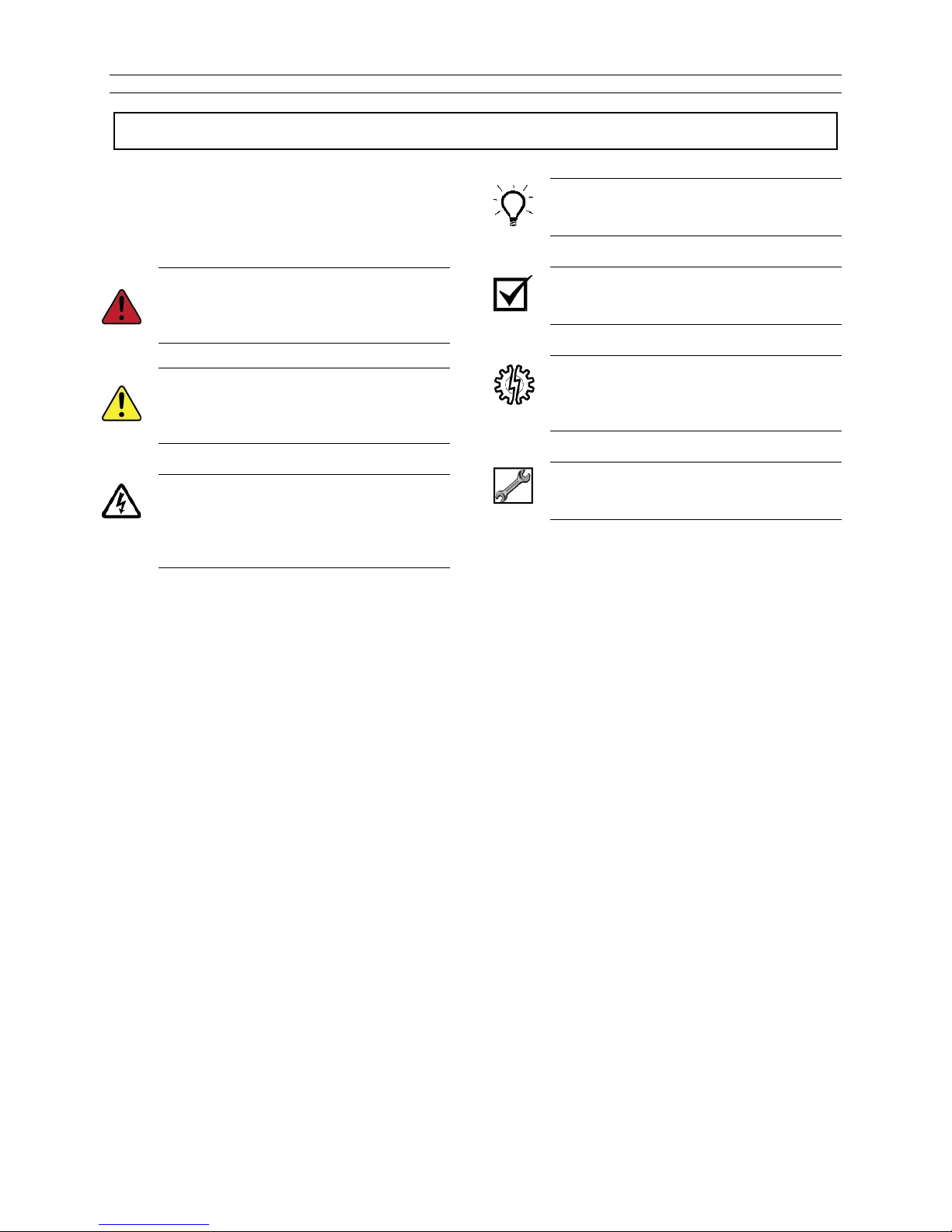
Text Symbols
In accordance with general safety and handling,
OSHA 1910.145, BS EN 809 and other local
directives, the following warning symbols and
signs are used in this manual.
DANGER: Text accompanied by this
symbol indicates failure to avoid hazards
identified with this symbol will result in
death.
WARNING: Text accompanied by this
symbol indicates that failure to recognize
these hazards could result in injury or
even death.
ELECTRICAL HAZARD: Text
accompanied by this symbol indicates
that failure to follow directions could
result in electrical damage to equipment
or electrical shock.
RECOMMENDED: Text accompanied by
this symbol indicates recommended
usage.
REMINDER: Text accompanied by this
symbol indicates a reminder to perform
an action.
EQUIPMENT USE ALERT: Text
accompanied by this symbol indicates
that failure to follow directions could
result in damage to equipment.
RECOMMENDED TOOL: Text
accompanied by this symbol identifies
the tool required for the operation.
SA-07-11-92, Rev Orig 2 October 2015
Page 10

Instruction and Operation Manual
Equivalent Terms
Units
To assist in global understanding the following equivalent terminology is used: -
Used in this manual Also known as
Alignment Pad Support Gasket
Bush Radial Bearing or Journal Bearing
Bearing Assembly Power Frame
Containment Shell Shroud
Gasket Joint
Spanner Wrench
Fit Install
Grounding Earthing
Check Valve Non Return Valve
Both Metric and equivalent US units are shown in this manual where appropriate.
Conversion factors between units are: -
°C to °F multiply by 1.8 and add 32
mm to inches divide by 25.4
Nm to lbf-ft divide by 1.356
ml to US Fl.oz divide by 29.6
SA-07-11-92, Rev Orig 3 October 2015
Page 11
Instruction and Operation Manual
Equipment and Safety Precautions
Sundyne LLC manufactures centrifugal pumps
to exacting International Quality Management
System Standards (ISO 9001) as certified and
audited by Lloyd’s Register Quality Assurance
Limited. Genuine parts and accessories are
specifically designed and tested for use with
these products to ensure continued product
quality and performance. Sundyne cannot test
all parts and accessories sourced from other
vendors; incorrect design and/or fabrication of
such parts and accessories may adversely affect
the performance and safety features of these
products. Failure to properly select, install or use
authorized Sundyne pump parts and
accessories is considered misuse and damage
or failure caused by misuse is not covered by
Sundyne’s warranty. Additionally, modification
of Sundyne products or removal of original
components may impair the safety of these
products and their effective operation.
CHEMICAL HAZARD
Sundyne pumps may handle hazardous,
flammable, and/or toxic fluids. Proper personal
protective equipment should be worn.
Precautions must be taken to prevent physical
injury and compliance must be ensured with
COSHH, EPA or any applicable Health and
Safety legislation. Pumpage must be handled
and disposed of in accordance with applicable
environmental regulations.
Safety procedures must be applied
prior to any installation, maintenance,
or repair of a Sundyne pump. Failure to
follow safety precautions may lead to
injury!
All pumps returned to Sundyne or HMD
for servicing must have a
decontamination certificate and the
appropriate Health and Safety data
sheets.
Wearing Personal Protective
Equipment
To ensure safety, protective equipment must be
worn at all times when installing, performing
maintenance, or repairing equipment. The
following safety recommendations must be
adhered to for optimum safety:
Safety glasses with side shields that meet
ANSI Z87.1 standard for impact resistance
must be worn at all times.
Protective footwear (steel-toe shoes)
meeting ASTM F2413-11 standard
specification for performance requirement
of protective footwear.
Hearing protection is strongly
recommended at all times when noise
levels exceed 85 dB during an eight (8.0)
hour period.
Chemical resistant gloves must be used
if chemicals are utilized (refer to Using
Chemicals for additional information).
A dust mask respirator must be worn if
chemicals have warning labels
regarding fumes, dust, or mists.
When using more than one piece of protective
equipment, consider their compatibility. For
example, safety glasses will not interfere with
hearing protection equipment. Be sure to clean
all pieces of personal protective equipment
immediately after each use.
Refer to Section 8 of the chemical specific
Safety Data Sheet for any additional PPE
requirements.
Lifting
Attention must be given to the safe handling of
all items. This applies to both installation and
maintenance. Where pumps, pump units, or
components weigh in excess of 35 lbs (16Kg) it
is recommended that suitable lifting equipment
should be used in the correct manner to ensure
that personal injury or damage to pump
components does not occur. Note that lifting
eyes fitted to individual pieces such as pump
and motor are designed to lift only this part and
not the complete assembly
Using Forklifts
Any persons operating a forklift must have an
active recognized operator license.
Before initializing forklift operation,
verify that the lift is in a safe operating
position.
SA-07-11-92, Rev Orig 4 October 2015
Page 12
Instruction and Operation Manual
Ensuring Electrical Safety
All electrical sources must be powered-off
before installation, service, or repair of
equipment occurs.
Sundyne recommends that a Lockout/Tag-out program be followed prior
to altering the equipment. Locks or
tags must be provided to warn
employees that equipment is
temporarily unavailable.
Once all work has been completed, the person
installing the lock or tag must remove it
according to company procedure.
Testing Equipment
Prior to performing a test on newly installed,
maintained, or repaired equipment; all personnel
in the immediate area must be warned.
Follow company procedures prior to
equipment testing at all times.
Magnets
Sundyne sealless pumps contain high
strength magnets which may, in some
circumstances, affect the operation of
certain types of medical implants such
as pacemakers. Wearers of these
implants should take extreme caution
when in proximity to a Sundyne
sealless pump. The assembled pump
presents no known problems, however
internal components need to be treated
with caution. Care should be exercised
with wristwatches and other sensitive
equipment from the strong magnetic
field when working around and handling
the Inner or Outer Magnet Rings.
Using Chemicals
Any chemicals to be used must be accompanied
by a relevant safety data sheet (SDS), in
accordance with government legislation. If
applicable, use chemical proof gloves.
An eye wash station (or equivalent)
should be available in the event of
injury. If any hazardous or flammable
chemicals pass through the equipment,
a complete decontamination of the
equipment is required.
Protection from Falling
Fall protection and associated preventative
measures are required when working on
equipment located four feet or higher from the
ground.
Follow company fall prevention
procedures prior to working on
equipment.
Preventative Machine Guards
Preventative guards must remain in place on all
equipment.
Only remove the guards while
performing maintenance or repair.
Replace the guards immediately after working
on the equipment and prior to start up.
EXPLOSION/FIRE HAZARD
Never use an acetylene torch, open
flame, or heat to attempt to remove
parts that have seized together in
Sundyne equipment. Any residual
process gas or liquid that is flammable
can result in an explosion or fire with
potential for serious injury or death.
Once all work has been completed, the person
installing the lock or tag must remove it
according to company procedure.
SA-07-11-92, Rev Orig 5 October 2015
Page 13
Instruction and Operation Manual
Three Inch
Suction
Two Inch
Pre-Commission Checklist
Familiarizing Yourself with the Pump
Before servicing and starting up the Sundyne
pump, carefully review all information on the
product, including:
Specification sheets
Outline drawings
Performance curves
Instruction and related manuals
System P&ID/Process Flow Diagram
(Clients equipment)
Control system and operational
philosophy/narrative (Client)
Familiarize yourself with the pump configuration
before starting and operating the pump.
Driver Instructions
Carefully follow all installation and starting
instructions provided by the driver manufacturer.
This information is included in the final data
package.
Verifying Auxiliaries
Before start up, verify that the following
auxiliaries are met:
Check the utility connections
Looking down
Verify that the auxiliary piping conforms
to Sundyne standards, as indicated in
the detailed specifications
Verify all switch and instrument
connections
Verify that all switch and instrument
settings are set to normal operating
standards
Calibrate all measurement equipment,
such as flow meters, ampere meters,
and pressure meters, etc.
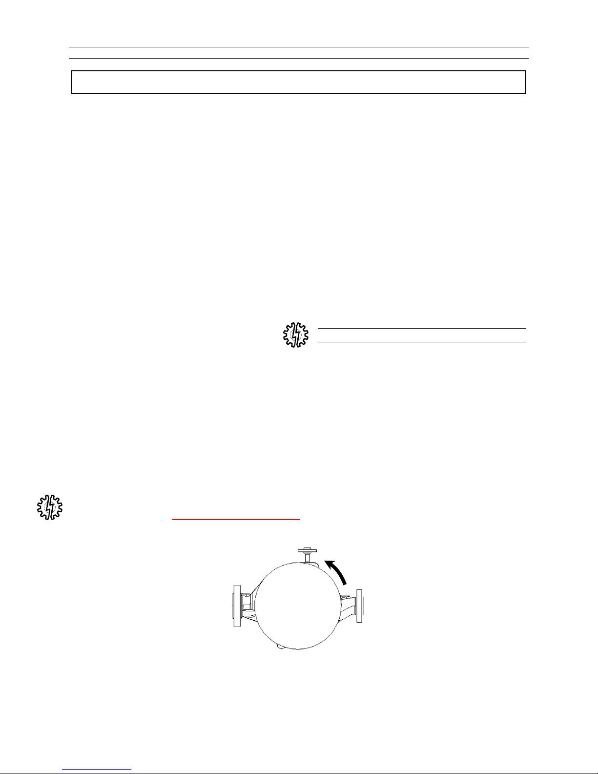
Checking Driver Rotation
Verify that the direction of the driver rotates in
the same direction as the arrow stamped or cast
on the pump casing.
Do not run pump dry
Piping Connections
Verify that the following bolted or threaded
connections are tight:
Pump flange bolts
Is a check valve in the discharge line?
Note: A start-up bypass line upstream of
the check valve is recommended
whenever feasible
Rotation of the driver must be counter-clockwise.
SA-07-11-92, Rev Orig 6 October 2015
Vent
View Looking Down
Impeller and Driver
Shaft Rotation
Discharge
Page 14
Instruction and Operation Manual
General
Application or Use
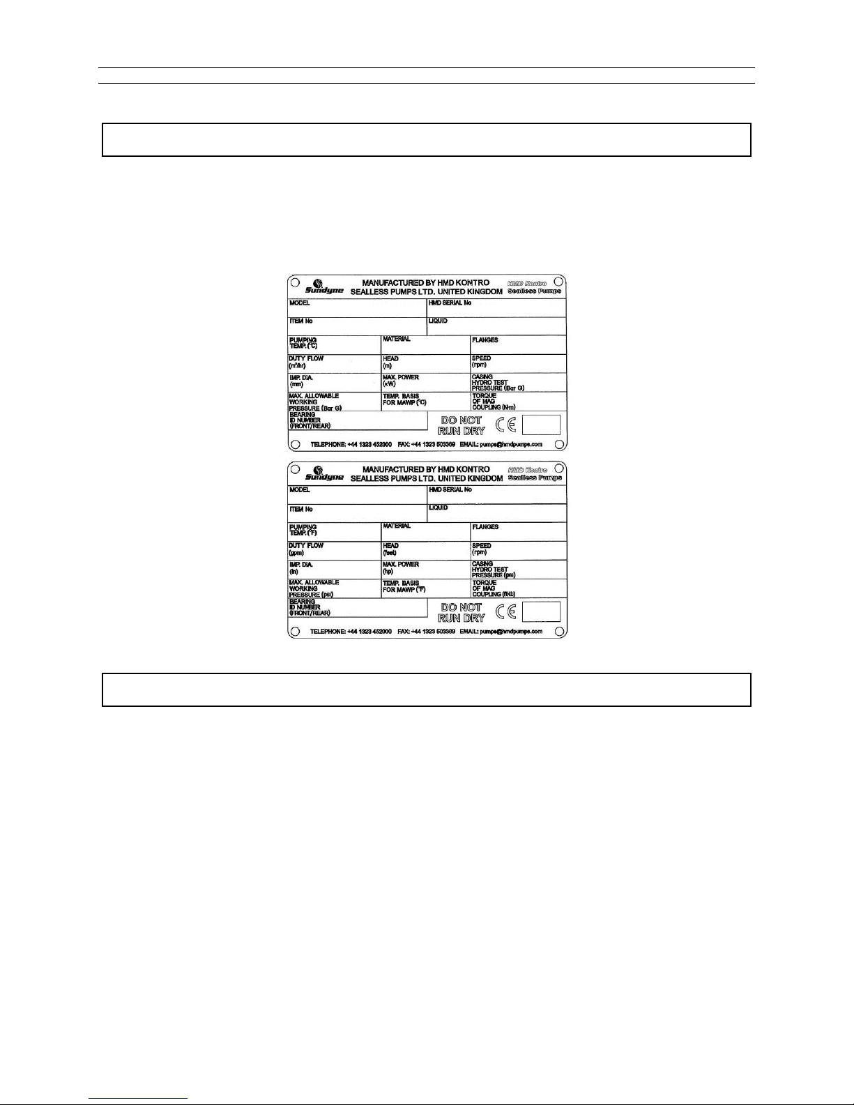
Each pump is designed for operation at the conditions stated on the pump label (Fig 1). Should the need
arise to operate the pump outside of the conditions indicated on the pump label, Sundyne should be
contacted to check and confirm that the pump can be operated safely at the revised operating conditions.
Fig 1
Temperature Classification - (ATEX Directive 94/9/EC)
The maximum surface temperature of a metallic magnetic drive pump is the highest temperature
ascertained from any one of the following conditions:
1. The temperature of the pumped liquid, plus 20C (68⁰F).
or
2. The ambient temperature plus 20C (68⁰F).
or
3. The ambient temperature plus 39C (102⁰F) (only in the case of separately mounted pumps
with oil lubricated bearing assemblies).
or
4. The temperature of the heating medium being used in the heating jacket (if fitted).
The actual classification is calculated by obtaining the maximum surface temperature and then
using the following table to obtain the relevant Temperature Class:
SA-07-11-92, Rev Orig 7 October 2015
Page 15

Table 1
Instruction and Operation Manual
Temperature
Class
T1 450
T2 300
T3 200
T4 135
T5 100
T6 85
Maximum Surface
Temperature (C)
Maximum Surface
Temperature (F)
842
572
392
275
212
185
Example:
The pump is pumping a liquid with a temperature of 120C (248⁰F). The pump is close coupled
and therefore does not have an external oil lubricated bearings. The maximum ambient
temperature in which the pump may operate is 30C (86⁰F)
Condition 1 equates to 120C + 20C = 140C (284⁰F).
Condition 2 equates to 30C + 20C = 50C (122⁰F).
Condition 3 does not apply.
Condition 4 does not apply.
Thus the maximum surface temperature of the pump is 140C which equates to a temperature
classification of T3.
The maximum surface temperature of a plastic lined non-metallic magnetic drive pump or a
ZeroLoss shell pump is the highest temperature ascertained from any one of the following
conditions:
1. The temperature of the pumped liquid, plus 10C (50⁰F).
or
2. The ambient temperature plus 10C (50⁰F).
or
3. The ambient temperature plus 39C (102⁰F)(only in the case of separately mounted pumps
with oil lubricated bearing assemblies).
SA-07-11-92, Rev Orig 8 October 2015
Page 16
Instruction and Operation Manual
INSTALLATION
Inspection
Inspect the shipping container for any damage
sustained during shipment. If damage is found,
note the nature and extent before unpacking. A
photograph is helpful in any claims to be made
against the shipper; also, inform Sundyne or the
local authorized distributor. Check the
nameplate data against the shipping papers and
against your purchase order to ensure that the
correct pump is supplied.
After unpacking check to see that the suction
and discharge flanges are sealed. If the seals
have come loose, examine the pump to ensure
no packing material or dirt is in the casing. It
may be necessary to remove the pump casing to
check. Refer to the Dismantling Instructions if
required.
Storing Your Pump Short-Term
Inspect the suction and discharge flanges to be
certain that they are free from scratches or nicks
and that they are clean. The gasket seating
surfaces in particular should be cleaned
carefully.
Ensure that a copy of this manual is in the hands
of the installation personnel and that they have
read it thoroughly before proceeding further.
The input shaft on the pump should turn
freely on the pump, however it should
not be turned excessively when the
pump is dry. Excessive rotation of the
shaft when the pump is dry may result
in damage to the bearings. If the input
shaft does turn freely, and if rotation is
“not smooth,” damage may have
occurred during shipping.
If your Sundyne pump is not to be installed
immediately but within the next 6 months,
protect it from exposure to moisture and dust.
The pump should be left undisturbed in its
transportation packaging and stored in a dry
area and not subjected to vibration.
If removal from the packaging is necessary, the
pump should be stored covered in a clean, dry
area protected from physical damage and
vibration. All flanged and threaded connections
should remain capped.
Note: Observe the storage instructions
provided by the driver manufacturer.
Storing Your Pump Long-Term
In addition to the precautions in the short-term
section above, additional precautions are
required for long-term storage.
If your Sundyne pump will not be operated for a
period of time exceeding six months from the
date of shipment, long-term storage conditions
must be met. Sundyne should be informed at
SA-07-11-92, Rev Orig 9 October 2015
the time of order that long term storage is
anticipated so that special packaging
arrangements can be made. These will consist
of:
The pump will be packed in a wooden
crate.
The pump will be packed with bags of
silica gel and covered with tar paper.
Page 17

Instruction and Operation Manual
All machined surfaces will be greased (if
appropriate).
All flanges and threaded connections
will be capped.
Recommended Long-Term Storage
Procedures
It is recommended that the pump should be left
in its transportation packaging and stored in a
dry area and not subjected to any vibration,
which may cause brinelling of the electrical
motor and pump bearings. At suitable intervals,
during a period of storage, the pump rotor
should be turned by hand.
After long term storage, when the pump is
installed, the grease and oil lubricated
Installation Guidelines
Location
Centrifugal pumps should be installed as close
as is practical to the source of liquid supply and
preferably below the liquid level in the supply
vessel.
Pumps installed on systems requiring suction
lifts need special consideration and Sundyne
should be consulted.
Pump units must be installed to ensure that
adequate space is available for access and
maintenance.
Sundyne supplies certified drawings showing
foundation details and the space necessary to
carry out routine inspection and maintenance
with every pump; extra drawings are available at
a moderate cost on request.
Foundations
Foundations may consist of any structure heavy
enough to afford permanent rigid support to the
full area of the pump base and to absorb any
normal strains or shock. Concrete foundations
built up from solid ground are the most
satisfactory.
assemblies should have the lubricants cleaned
out and replaced. Refer to the section 7.2.1 for
further details. This precaution is necessary
because lubricants can deteriorate after a period
of time.
Prior to installation it is recommended that the
pump is inspected by a Sundyne engineer and
that the commissioning is similarly supervised.
Note: Sundyne does not accept liability for
equipment damaged during the storage
period. Sundyne does not guarantee
the quality of equipment during and
after the storage period.
Note: Any inspection fees are the sole
responsibility of the purchaser.
When a pump unit is mounted on steelwork or
other such structures, care must be taken to
ensure that the baseplate is not subject to
distortion or vibration.
Where possible the pump units should be
mounted over or as near as possible to main
supporting members.
It may be necessary to mount pump units
resiliently if there is the possibility of excess
vibration. If in doubt, contact Sundyne or the
authorized distributor.
Misalignment should be corrected by shims.
Grouting may be necessary to prevent
movement of the pump and stop the
accumulation of chemical or hydrocarbon under
the pump base. The pump should be leveled by
shimming under the base prior to grouting the
channels that are to be filled with grout through
the access holes. The nuts on the foundation
bolts should not be tightened until the grout has
set for at least 48 hours. Fig. 2.
The pump base in the case of close coupled, or
the base plate in the case of separately mounted
pumps should be bolted securely in position with
suitable foundation bolts.
SA-07-11-92, Rev Orig 10 October 2015
Page 18

Instruction and Operation Manual
F
ig. 3
F
ig. 2
Electrical Installation & Grounding
Electrical connection of the pump motor, to a suitably rated power supply shall be carried out by
electrically skilled persons or staff. Care should be taken to ensure that the motor electrical connection
will not overload the power supply. Provision shall be made to enable electrical isolation of the
equipment.
Pumps that have been supplied in accordance to the ATEX Directive (94/9/EC) will be identified by a
label with the following symbol on it:
Such units are supplied with an M8 grounding stud, saddle washer, shake-proof washer and locking nut
located on the Coupling Housing (Item 43.43). Once the unit has been installed and levelled, this shall be
wired to ground with a suitable grounding cable, Fig 3, by electrically skilled persons or staff.
To further protect the integrity of the unit, an additional grounding connection can be made to the motor.
Typical Grounding
Arrangement via M8
Grounding Stud
SA-07-11-92, Rev Orig 11 October 2015
Page 19
Instruction and Operation Manual
10 x Pipe
Minimum
Fig.4Fig.
5
Suction and Discharge Piping
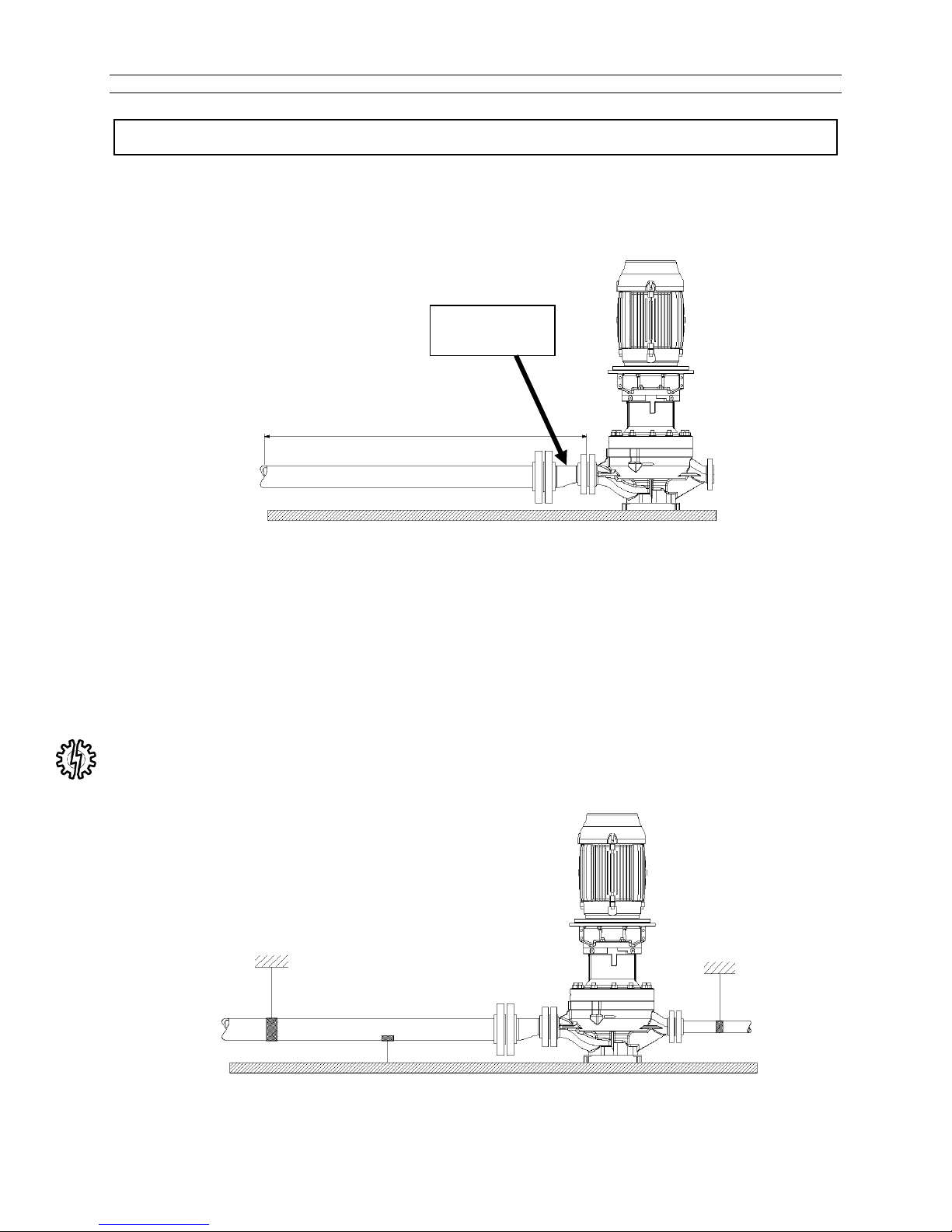
Good practice dictates that there should be a minimum straight length of pipe on the suction flange of the
pump equal to ten times the suction pipe diameter. This is to allow the liquid to flow into the pump casing
without turbulence. (Fig. 4)
Eccentric
Reducer
In addition, it is also good practice to use suction pipeline at least one to two sizes larger than the pump
nozzle and reduce the pipe diameter at the pump flange. When doing so, insure the eccentric reducer is
installed as shown with sloped side facing down (Fig. 4).
Ensure that the inside diameter of the suction pipe matches the nozzle openings as accurately as
possible in order not to strain the pump casing. On no account lever the suction pipe flange to align it to
the pump suction nozzle flange. The flange bolts should slip in to the aligned flange holes without
straining the pipework.
Apply proper support to suction and discharge piping with proprietary pipe hangers or supports to keep
the strain off the pump casing. (Fig. 5)
SA-07-11-92, Rev Orig 12 October 2015
Page 20
Instruction and Operation Manual
10 x Pipe
Minimum
Fig.
6
10 x Pipe
Minimum
Fig.
7
10 x Pipe
Minimum
Fig.
8
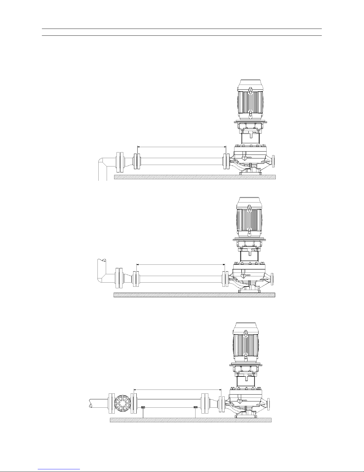
Ensure that all joints in the suction pipework are airtight.
Install suction piping, elbows, eccentric reducers (flat side up as in Fig 6) and all other fittings so that no
air pockets can be created within the suction system.
Position of eccentric reducer when liquid is below pump centerline. (Fig. 6)
Position of eccentric reducer when liquid is above pump centerline. (Fig. 7)
Mount valves from the suction pipework with the stems horizontal or vertically down to avoid air pockets.
(Fig. 8)
SA-07-11-92, Rev Orig 13 October 2015
Page 21
Instruction and Operation Manual
GV2
Fig.
9
Pitfalls to Avoid On Suction Pipework
Avoid the use of valves that have high friction loss.
Avoid the use of in-line filters (with the exception of the commissioning period)
Avoid pipework layouts that promote vortices at the liquid level in the supply vessel.
Avoid the use of multiple spring type check valves.
Avoid flow meters.
Avoid at all costs a pipework system that may allow the pump to run dry.
Avoid using more than one pump feeding at the same time from a common suction pipeline.
Avoid any operating conditions that reduce the NET POSITIVE SUCTION HEAD (See section covering
NPSH).
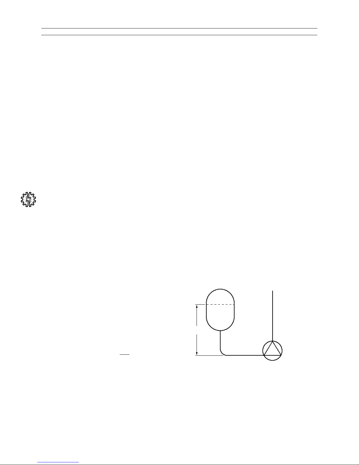
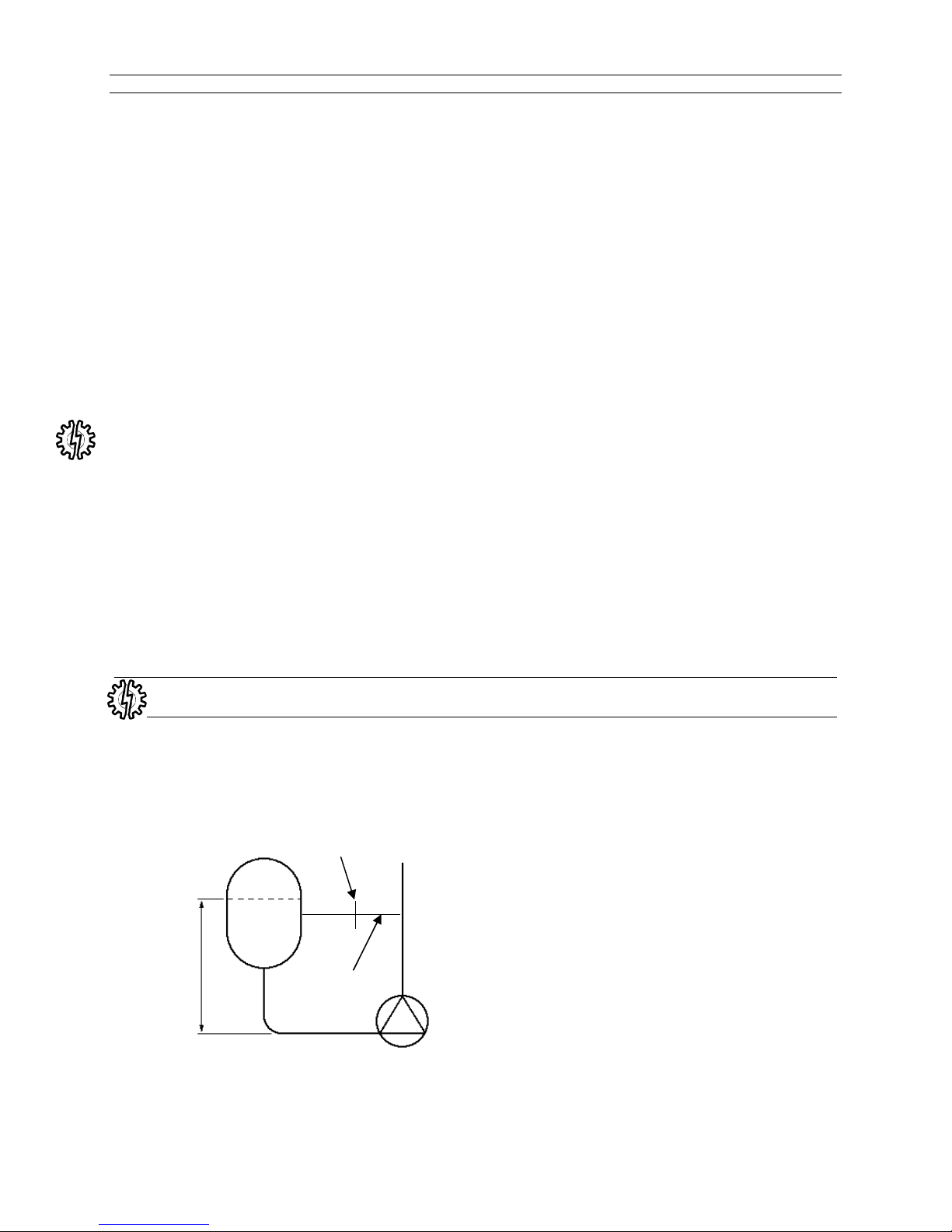
Net Positive Suction Head (NPSH)
Liquids cannot be towed or dragged down a pipe; liquids can only be pushed along a pipe. The push the
liquid needs to flow in to the pump can only be supplied by some external energy source such as the
absolute pressure in the surface of the liquid in the vessel and the head of the liquid over the center line
of the pump.
A system that has insufficient NPSH available will cause the pump to cavitate. The general effects of
cavitation are noise, erosion of metal surfaces and vibration of the system. The latter situation will result
in the magnetic coupling overheating and the product-lubricated bearings will wear rapidly. Cavitation
starts when the pressure at the pump suction falls near to the value of the vapor pressure of the pump
liquid and this varies with temperature.
At the time the pump is selected, the NPSH available will have been calculated as per the following
method: -
Ps
NSPH available = Ps-Vp+Hs+Vs-Hf
Where:
Ps = Absolute pressure in suction vessel
Vp = Vapour pressure of liquid
Hs = Total static head
Hf = Friction losses in suction line
2
Vs = Velocity Head =
Hs
Vp
Hf
In the above equation, all parameters must be converted to meters head of liquid before the liquid
calculation is carried out. The pump should be selected so that the NPSH available is a minimum of 0.5m
(1.6 ft) greater than the NPSH required by the pump.
No subsequent alteration should be made to the pipework system without considering the effect that it will
have on the NPSH available.
SA-07-11-92, Rev Orig 14 October 2015
Page 22
Instruction and Operation Manual
Discharge Pipework
The discharge pipework and its related equipment does not normally have as great an influence on pump
performance as the suction pipework. There are, however, some points to watch with discharge pipework
to ensure efficient pump operation.
In a manner similar to the suction pipework, provision must be made to support the discharge pipework
and any other equipment.
The discharge pipework is normally more extensive than the suction system, so there are increased
amounts of pipe strain being transferred to the pump and this must be avoided.
Where possible, there should be a straight length of pipe immediately on the discharge nozzle followed by
a suitable valve and between the valve and the discharge flange there should be a pressure gauge to
help monitor the pump's performance.
Should a check valve be fitted in the pump discharge line, provision should be made to vent the space
between the pump and the check valve or the pump will not prime.
It cannot be stressed enough, how important it is to have pressure gauges on both the suction and the
discharge sides of the pump.
Should a bypass be incorporated in the system, the bypass line should incorporate an orifice plate to
ensure that the pump – in bypass mode - operates at the specified minimum safe flow (Fig. 10).
The bypass system should not be led back to the pump suction directly; it should be led back to the
supply vessel to dissipate any heat built up during the bypass cycle.
Motorized valves should be controlled such that they do not deadhead the pump whilst it is running.
It is also important that the system and its operation cannot permit the pump to lose differential head as
any substantial loss of head could cause damage to the pump.
Never use force to position piping into place at the flanged suction and discharge connection
locations. Failure to have piping properly aligned may impose excessive strains on the unit.
To ensure correct hydraulic performance, the orifice plate, when supplied must be installed, clamped on
center between the pump discharge nozzle and the discharge pipe flange.
Fig. 10
Orifice Plate
Bypass line
SA-07-11-92, Rev Orig 15 October 2015
Page 23

Instruction and Operation Manual
Protection Systems
To minimize the effect of process or system malfunction the LMV 801S Sealless Pump can be provided
with various fail safe devices to increase plant security.
The type of instrumentation or safety devices offered depends on the properties of the process liquid, the
application and plant operating procedures.
It is rare, that all of the protection methods illustrated are needed and the number or type of protective
device fitted is often a matter of client experience and preference.
Power Control Monitor (PCM)
Protects Against
Dry Running
Pump Seizure
Cavitation
Motor Faults
Closed Valve
Motor power monitoring can provide good pump protection against low flow or dry running. Being remote
from the pump head the power sensor is not affected by the liquid handled and is, therefore, more reliable
than differential pressure or flow switches.
Temperature Sensor
Protects Against
Dry Running
Closed Head and Minimum Flow
Internal/External Bearing Wear
Pump Seizure
Severe Cavitation
Process Overheating
The containment shell provides pressure retention of the liquid cooling the pump bearings. The
temperature sensor monitors the temperature of the outside diameter of the containment shell detecting
temperature movements in response to operational change. The temperature sensing device, therefore,
provides an optimum, inexpensive form of continuous pump protection. Normally an over temperature cut
out and/or alarm is required, but low and high trips can be provided for liquids which can freeze at
ambient air temperatures.
Differential Pressure Switches
Protects Against
Dry running
Minimum/Maximum Flow and Closed Head
Severe Cavitation
Pump Seizure
It is essential that sealless pumps are not run dry otherwise rapid bearing wear and heat buildup will
occur. Differential pressure switches are reliable and economic forms of dry running protection. These
failsafe devices are particularly suited to applications where the risk of suction starvation is high. The
switch contacts are wired into the motor control circuit to provide a pump cut-out in the event of a drop in
pump differential pressure.
SA-07-11-92, Rev Orig 16 October 2015
Page 24

Instruction and Operation Manual
Liquid Sensing Probe
Protects Against
Internal Liquid Leakage
Starting the pump dry
This instrumentation is usually installed in conjunction with a pressure tight coupling housing. An early
warning of internal leakage is given before dangerous quantities of spillage can fill the housing. Another
use for the liquid sensing probe is to ensure that the pump is primed with liquid before it can be started.
When used for this, the liquid sensing probe is mounted at the pump discharge flange.
Secondary Containment or Control
Protects Against
Leakage to Atmosphere
Hazardous Emissions
Where a requirement for secondary containment or control exists, a sealed coupling housing is used to
provide secondary pressure retention, to contain or control fluid leakage. The sealed coupling housing is
pressure tested to the same hydraulic pressure rating as the pump liquid end. The drive shaft is fitted with
a sealing system to suit.
The sealed coupling housing can be configured with optional flanged, top vent and drain vent ports to
enable connection to different sensors and to enable the safe disposal and flushing of a system, in the
unlikely event of a primary containment breach.
Although not always required, the pressure tight housing is desirable for very toxic or flammable
chemicals.
The sealed coupling housing can be specified with a variety of sensors, varying in sensitivity from; the
Liquid Sensing Probe (refer to previous section), a pressure switch or a gas or vapor detector. These
sensors along with the shaft sealing system are configured to either prevent or limit any liquid or vapor
escaping the primary pressure boundary from entering the power frame and its bearings.
If you require further information on secondary containment or control options, or pump protection devices
please contact Sundyne/HMD or your local agent.
VapourView®
Protects Against
Dry Running
Gas or Vapour Related Process Upsets
Gas in System or Vapourisation
Pump Seizure
VapourView® is a patent protected instrument that sits outside the primary pressure boundary and uses
ultrasonic technology to monitor the presence of gas or vapour in the containment shell. In addition to
protecting the operation of the magnetic drive pump the VapourView® instrument provides vital
information to an end-user on the condition of the process liquid.
It is strongly recommended, that as a minimum, power sensing protection with a Power Control
Monitor is used to ensure long and safe operation of your sealless pump. This is particularly
relevant to pumps being used in potentially explosive atmospheres.
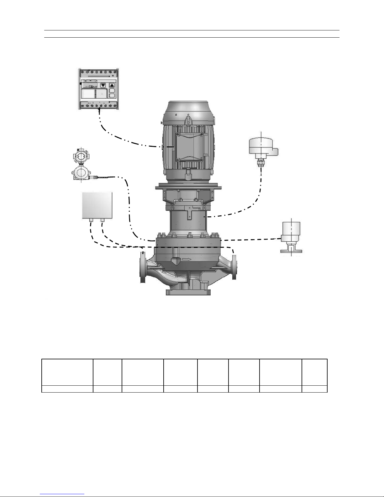
For guidance on the availability of protection systems for a specific pump range, please refer to Fig. 11
and Table 2.
If you have a specific requirement, contact Sundyne/HMD to discuss the available options in more detail.
SA-07-11-92, Rev Orig 17 October 2015
Page 25
Instruction and Operation Manual
Fig. 11: Protection Systems (Typical)
Power
Control
Monitor
Vapour
View
Liquid
Level
Probe
Temperature
Sensing
Device
Differential
Pressure (DP)
Switch
Table 2: Availability of Instrumentation
Model Prefix Power
Control
Monitor
LMV 801S
Note: Any instrumentation installed in a Potentially Explosive Atmosphere should be ATEX certified.
1
In some cases the connection of DP switch is made into suction and discharge piping and not the pump casing.
Temperature
Sensing
Device
Differential
Pressure
Switches
1
Pressure
Tight
Coupling
Housing
Liquid
Sensing
Probe
Secondary
Containment
or Control
Vapour
View
SA-07-11-92, Rev Orig 18 October 2015
Page 26
Instruction and Operation Manual
ABCDEFG
S
Pipe Flow Area
Strainer
Precautions
Installation Considerations
A significant proportion of all pump problems occur during the commissioning period. There are a number
of reasons for these problems and usually they are not as a result of poor materials, bad workmanship or
design of the pump.
Normally, the problems encountered during commissioning are due to:
Debris left in the system during the construction period
Unexpected system characteristics
Incorrect pump selection
Every effort should be made to ensure that debris is removed from the pipework and related equipment
prior to installing the pump.
The pump should not be installed until all pipework has been flushed to remove washers, nuts, welding
slag, welding rod, studs, pieces of gasket material, pieces of rag, shot etc.
When the system has been cleared, the pump can be installed but provision should be made to install a
temporary filter in the suction pipework close to the pump.
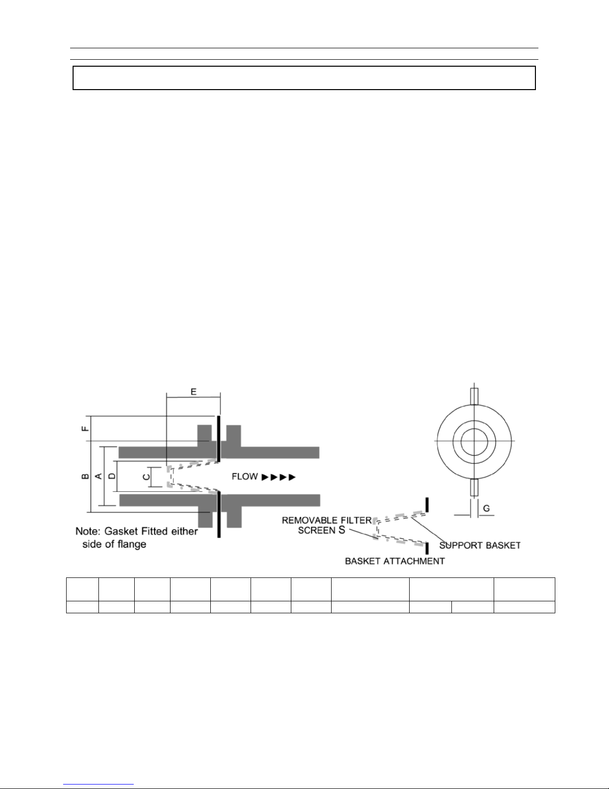
The recommended filter size and the method and position of it installation are shown in Fig. 12 and
Fig. 13.
Fig. 12
ALL DIMENSIONS ARE INCHES
SCH 40 SCH 80
3 5 1.75 2.69 6.5 3.5 1.5 40 X 40 Mesh 7.39 6.6 28.4
Note: Basket made from 16 SWG compatible with pump liquid
Flow Area
The filter consists of a 16 SWG metal basket (metal to be compatible with commissioning liquid) and a
40x40 mesh wire screen cloth.
The table in Fig 12 shows the relationship between pipe diameter, its flow area and the strainer flow area.
Do not use a flat spade type screen in the system, the flow area will be less than the pipe flow area and
this may create problems due to rapid blockage.
SA-07-11-92, Rev Orig 19 October 2015
Page 27
Instruction and Operation Manual
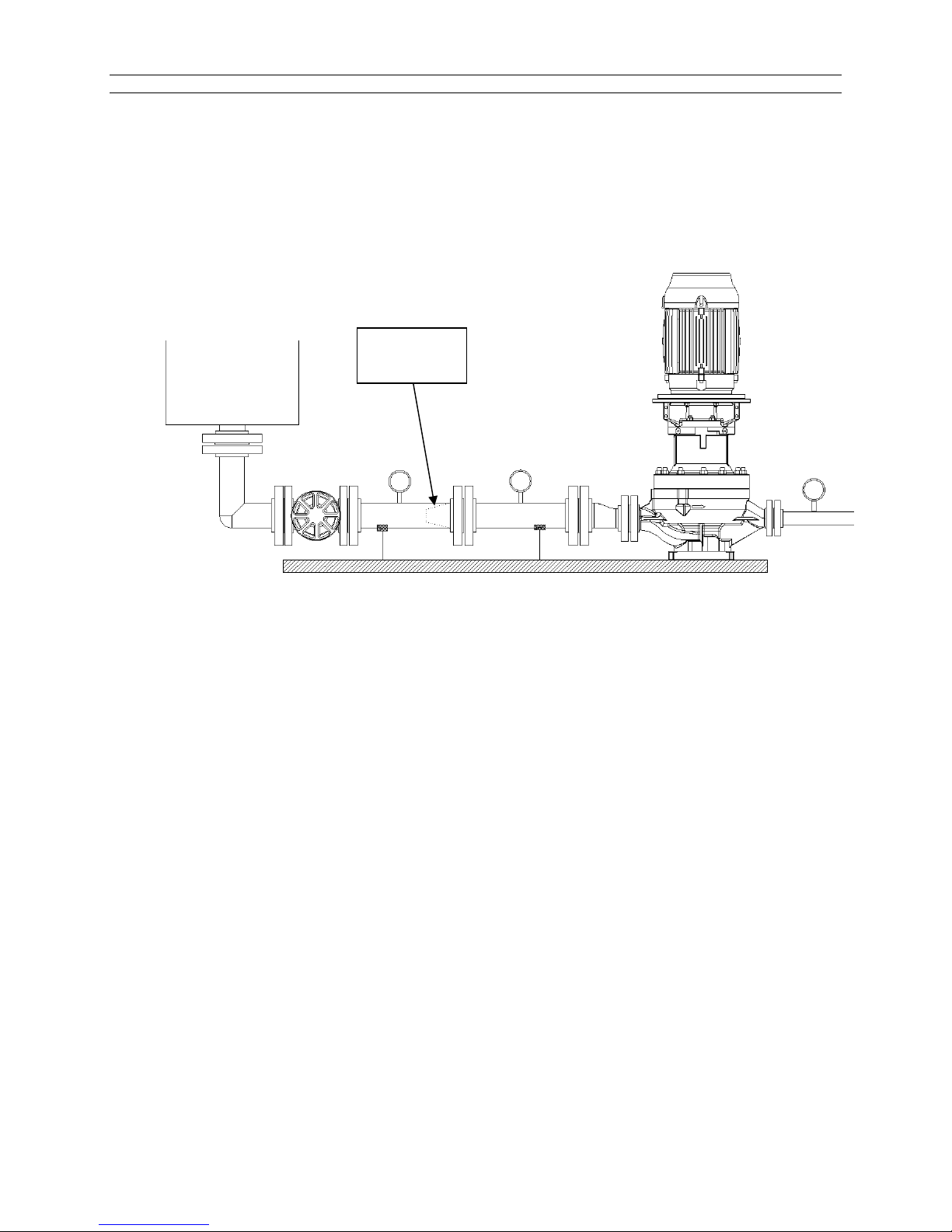
Fig.13.
Pressure Gage and
Temporary Filter
Installation
Fig. 13 shows how the temporary filter is installed in the system. It is important that all the gauges (PG1,
PG2 and PG3) are installed; PG2 and PG3 will indicate if the filter is blocking and PG2 and PG1 will
monitor the differential head across the pump to check that the pump is achieving duty.
After commissioning, gauges PG1 and PG2 should be installed permanently as they afford excellent
continuing checks on the pump’s performance.
Temporary
Filter
PG3
PG2
PG1
The gauges should be calibrated in the same units and measure absolute pressure.
All pipework and related equipment should be checked to ensure it is installed correctly and is leak free.
SA-07-11-92, Rev Orig 20 October 2015
Page 28
Instruction and Operation Manual
Commissioning
General
The LMV-801S pump is a vertical in-line type
pumps and is normally close coupled to the
drive motor. Prior to initial start-up, special
attention must be given to both checking the
direction of rotation and to venting any trapped
air from the pumps.
The LMV-801S pump must never be run against
a closed discharge valve.
Venting
Purpose
Internal rotating parts are supported by plain
bearings that are lubricated with the liquid being
pumped. It is imperative that all internal bearings
are immersed in the pumped liquid before the
pump is run for the first time after installation or
maintenance. Proper venting of the pump will
ensure all bearings are flooded and ready for
start-up.
Method
The following method for venting can be used
for the LMV-801S pumps.
Open both suction and discharge lines to
flood pump
Wait 5 minutes
Open the vent line to purge air, close vent
line
Wait 5 minutes
Open vent line a second time to purge
remaining air, close vent line
Pump is now ready for direction of rotation
check.
On pump startup, check that discharge
head is within expected operating range. If
discharge head is lower than expected, vent
pump once more.
Direction of Rotation
Ensure pump is full of liquid prior to checking
direction of rotation – Never run the pump dry,
even briefly to check rotation.
Fill pump with liquid and vent as above
Connect motor terminals to power supply
Remove motor cowl to observe motor fan
Check direction of rotation labelling on pump
Briefly energize motor to check direction is
correct
If direction is wrong, swap over two phases
on the terminal block
Re-check direction
Replace motor cowl
Pump is now ready for start-up providing the
proper venting procedure has been carried out.
Refer to section for Pump Operation.
SA-07-11-92, Rev Orig 21 October 2015
Page 29
Instruction and Operation Manual
START UP
Start-Up Procedures
Run-In
If the pump is to be run under conditions which
are considerably different from those conditions
listed on the spec sheet (such as a change in
specific gravity, suction pressure, flow rate, etc.)
the factory should be consulted to ensure that
the run-in conditions are compatible with the
pump.
Start Up
Close all drains; open the suction and discharge
valves fully and allow the pump to fill with liquid.
Open the vent line and allow gas to vent
appropriately, prior to starting the pump. Allow
pump to vent until all gas has escaped and only
liquid flows. Refer to the section Venting for the
recommended procedure.
Do not energize the motor until the pump has
been completely filled with liquid.
Check that the motor rotates in the same
direction as the indicating arrow.
Wait ten to fifteen seconds and the repeat step
above. You may have to repeat this sequence
several times before the discharge pressure
goes to the correct reading and remains steady.
At that time, the pump is fully primed.
With the pump running fully-primed, you should
listen for any unusual noises. Metallic scraping
sounds would be obvious signals to shut down
the pump. Refer to section Operating Guidelines
to locate the source of these noises.
If the pump emits a rumbling noise from the
casing end, the problem is cavitation. Cavitation
is the formation of vapor bubbles in the eye of
the impeller and their subsequent collapse within
the pump. Cavitation is usually due to
inadequate NPSH available. Stop the pump and
check there are no obstructions in the suction
pipework system. Recheck the NPSH available
and ensure that this is at least 0.5 meters (1.6
feet) greater than the pump requires.
Do not continue to run the pump under
!! WARNING !! Under NO circumstances
should the pump be run in the reverse
direction!!
Close down the discharge valve so that it is
about one quarter open. This is done to prevent
excessive loading of the pump or driver when
starting.
The LMV-801S pump must never be run
against a closed discharge valve.
Fix your attention on the discharge pressure
gauge (PG1 – see Fig. 13) and start the motor.
The pressure should rise quickly and remain
steady. If it hesitates and drops back to a lower
level, even momentarily, stop the pump. The
erratic pressure behavior is a sign that air and/or
vapors are being purged from the pump.
SA-07-11-92, Rev Orig 22 October 2015
cavitating conditions.
Call the system designer to check the
calculations.
When the cause of the cavitation is established
and corrected, continue the commissioning.
The differential pressure should now be checked
by subtracting the suction pressure gauge
reading from the discharge pressure gauge
reading and the answer is the differential
pressure in absolute terms.
This pressure should then be converted to
meters head of liquid taking into account the
specific gravity of the liquid.
Page 30
Instruction and Operation Manual
When the head has been calculated, it should
be compared with that stamped on the pump
nameplate. Any variation should be investigated.
All of these startup steps and checks can be
made in a relatively short time. The only
remaining requirement is to monitor for particles
or debris content in the pumped liquid over a
period of time. Some systems will only require
twenty-four hours of monitoring whilst others
may need much more. The actual time required
depends on the pumped liquid & the process
conditions.
Check the pressure drop across the start-up
filter (PG3-PG2) continually. Under NO
circumstances should PG2 be allowed to drop to
the point where the NPSH available at the
suction flange drops below required level. The
danger pressure should be known before
commissioning. (Fig. 13) is system related.
When the pressure drop (PG3-PG2) increases,
the temporary screen is becoming clogged with
particles and should be cleaned out. This will
require closing down the discharge and suction
valves to isolate the pump and screen. After the
strainer has been cleaned and re-installed, the
pump will have to be primed just as on initial
start-up. (Fig. 13).
Examine the debris and/or particles removed
from the strainer each time it is cleaned. The
strainer contents should be foreign matter to the
process and it will take longer and longer for the
strainer to clog up. If no new debris shows up for
a reasonable period of time then the temporary
strainer and pressure gauge PG3 can be
removed. (Fig. 13).
If the temporary strainer keeps clogging up at a
relatively even pace and the clogging material is
process-orientated particles, such as
undissolved crystals, “high boiler” compounds or
other entrained particles which are expected to
continue forming in the pumped liquid, some
permanent modification to the pumping system
may be required.
If the temporary filter continues to become
clogged, it is encouraged to review the problem
with Sundyne/HMD. To be of greatest
assistance to you at the time we would like to
know: -
a) The chemical composition of the solids
b) The percentage weight concentration
c) The size of the largest particles involved
d) The relative hardness of these solids
The more we know about the problem, the better
our chances of suggesting a permanent solution
to the problem.
Operating Guidelines
Consequently the power delivered to the
impeller heats the pumped liquid which can
overheat and vaporize. If the liquid vaporizes,
Precautions
The simple precautions required under operating
conditions are as follows: -
DO NOT RUN THE PUMP DRY
Dry running the pump will cause the pump shaft
bearings to lose lubrication flow resulting in
premature wear and failure, which can occur in
minutes. To guard against this a Power Control
Monitor (PCM) can be supplied by Sundyne/
HMD.
DO NOT RUN THE PUMP CONTINUOUSLY
WITH THE DISCHARGE VALVE CLOSED
The power required by the impeller does not
decrease to zero, as the flow reduces to zero.
SA-07-11-92, Rev Orig 23 October 2015
then lubrication of the bearings will be lost
causing premature wear and failure.
DO NOT ALLOW THE PUMP TO CAVITATE
Piping changes, process temperature, changes
in the level of liquid in the suction supply tank
can change the NPSH available resulting in
cavitation. Cavitation will damage any pump
severely in a short period of time.
Page 31

Instruction and Operation Manual
PUMPS IN PARALLEL
Should two pumps be supplied to operate in
parallel, to meet a specific duty. It is essential
that extreme care be taken in controlling the flow
rate of any one of the two pumps in the
eventuality that the second pump is stopped.
Without careful control of the flow rate of the
operating pump, then this pump will experience
a very low system resistance and as a result will
operate at a significantly higher flow rate than
that specified, leading to bearing failure and/or
cavitation problems.
INSUFFICIENT AND EXCESSIVE FLOW
The pump should not be operated below its
specified minimum safe flow rate due to
excessive loads and increased heat input into
the pumped liquid, leading to bearing failure.
JACKETS
If the pump has been fitted with heating jackets
or trace heating it is essential that this jacket be
heated to its operating temperature and that the
pump has been given sufficient time to increase
the product temperature to the correct value
prior to starting the pump.
LOW AMBIENT TEMPERATURE
Care should be taken when starting pumps after
they have been subject to excessively low
ambient temperature, due to the possibility of
frost forming on the outer magnet ring and
rolling element-bearing races. This could be
sufficient to prevent the pump starting and
leading to motor overload or magnet coupling
disengagement & subsequent damage.
The pump should not be operated at flow rates
significantly in excess of those specified. This
will lead to high bearing loads, low differential
head and cavitation resulting in subsequent
pump damage. Sundyne/HMD should be
consulted for advice on maximum flow limits.
SUCTION TANK
It is essential that good practice be observed in
the design of suction pipework and vessels to
ensure sufficient submersion of the pipework is
maintained and that air entrainment and vortices
are not present.
OVER PRESSURE
It is essential that the pumping system is not
over pressurized and that the discharge
pressure of the pump does not exceed the
design rating of the equipment.
HIGH TEMPERATURE
It is essential that the temperature of the system,
to which the pump is connected, is monitored
accurately and that the pump does not
experience temperature excursions that exceed
the rating of the equipment.
NON RETURN VALVES
Care should be exercised in the fitting of nonreturn valves to discharge pipework as this may
prevent correct venting of the pump prior to start
up.
STAND BY PUMPS
These should be primed fully then left with the
line valves closed to prevent process debris
accumulating and causing blockages.
APPLICATIONS
The equipment should only be used for the
application(s) for which it was supplied. Use of
this equipment on applications with a
significantly different specific gravity, vapor
pressure or specific heat could lead to pump
failure.
MOTORS
The equipment should only be used with the
motor specified at time of order. The motor
frame size should not be changed without prior
approval from Sundyne/HMD.
The continuous operating temperature for
pumps with a ZeroLoss shell is 120°C.
THERMAL SHOCK
Pumps should not be subject to thermal shock
unless specifically designed for this, because
this may lead to premature failure of the internal
bearings. In general pumps should not be
heated or cooled at a rate greater than 10ºC per
minute.
SA-07-11-92, Rev Orig 24 October 2015
REMOVAL OF PROTECTION DEVICES
No protection device such as condition
monitoring equipment, or guards supplied by
Sundyne/HMD should be removed from the
equipment without prior approval.
MODIFICATION TO PARTS
The user should, under no circumstances,
modify parts or use parts other than those
manufactured by Sundyne/HMD. Sundyne/HMD
Page 32

Instruction and Operation Manual
employ rigorous design, Quality and inspection
techniques and the use of unapproved
components may invalidate warranty conditions
and seriously compromise safety.
SOLIDS
It is essential that this pump is not operated with
the solids greater than that specified at time of
order as this could lead to blockage of internal
flow passages and the wearing of components.
DEBRIS
Suction strainers should be used during
commissioning of new plant to ensure that
commissioning debris does not enter the suction
of the pump.
FILTER SYSTEMS
If filter systems and cooling flow pipe valves are
fitted it is essential that:
The filter is cleaned regularly to ensure
sufficient flow is present.
All valves are open and no restrictions
to flow are placed in the cooling loop.
VENTING
The pump and associated pipework should be
fully vented prior to running to ensure no gas is
present at the suction of the pump.
COMMISSIONING
Care should be exercised in commissioning a
pump with a significantly higher specific gravity
liquid (>20%) than that specified for the product.
If in doubt consult Sundyne/HMD.
ROUTINE STARTING OF THE PUMP
This should be carried out with the pump primed
fully, the suction line valve open fully and the
discharge line valve approximately one quarter
open.
MOUNTING
Pumps and base plates must be located in
accordance with Sundyne/HMD’s
recommendations. It is essential that these
components be securely mounted to prevent
movement.
COUPLINGS
Care should be exercised in aligning the pump
drive shaft coupling to ensure that runout is
minimized with the pump at operating
temperature.
DIRECTION
It is essential that the pump is only run in the
direction specified by Sundyne/HMD. Failure to
do this may result in excessive heating of the
product and subsequent damage to the pump.
VIBRATION
Resonance of the pump assembly during
operation should be avoided. Pump assembly
resonance may result from structural piping
vibrations or be due to the rotational frequency
of the pump and motor (see also section
Vibration Levels).
NOZZLE LOADS
Pumps should not be subject to excessive
nozzle loads as this may lead to casing failures
and misalignment of couplings. For the
maximum allowable nozzle loads for a specific
pump model contact Sundyne/HMD.
LUBRICATION
Pump lubrication shall use the correct grade of
oil at the scheduled intervals. Care shall be
taken to prevent contaminants and moisture
from entering the oil and causing premature
bearing failure.
PUMP DRIVE END BEARINGS
On separate motor units the bearings are either
grease or oil lubricated as standard. Relubrication should be carried out every
1500/2000 hours with Shell Alvania RA Grease
(Aeroshell 7 Grease for sub-zero service). Oil
lubricated bearing assemblies, use Castrol
Hyspin AWS 68 Oil, or approved equivalent,
which should be changed every 4000 hours or
more frequent intervals in hot conditions.
MOTOR BEARINGS
The motor bearings shall be greased in
accordance with the bearing re-lubrication
instructions issued by the motor manufacturer.
SA-07-11-92, Rev Orig 25 October 2015
Page 33
Instruction and Operation Manual
Single Operation
Parallel Operation
Controlling the Pump During Startup
To ensure control of the pump during start up,
follow the start-up procedures for your desired
configuration.
Start the pump with the suction valve open while
throttling the discharge valve. This will ensure
that the pump will reach the design flow
operating point.
If the process fluid is near its vapor pressure,
open the supply vessel seal cavity vent so that
the pump can fill with liquid.
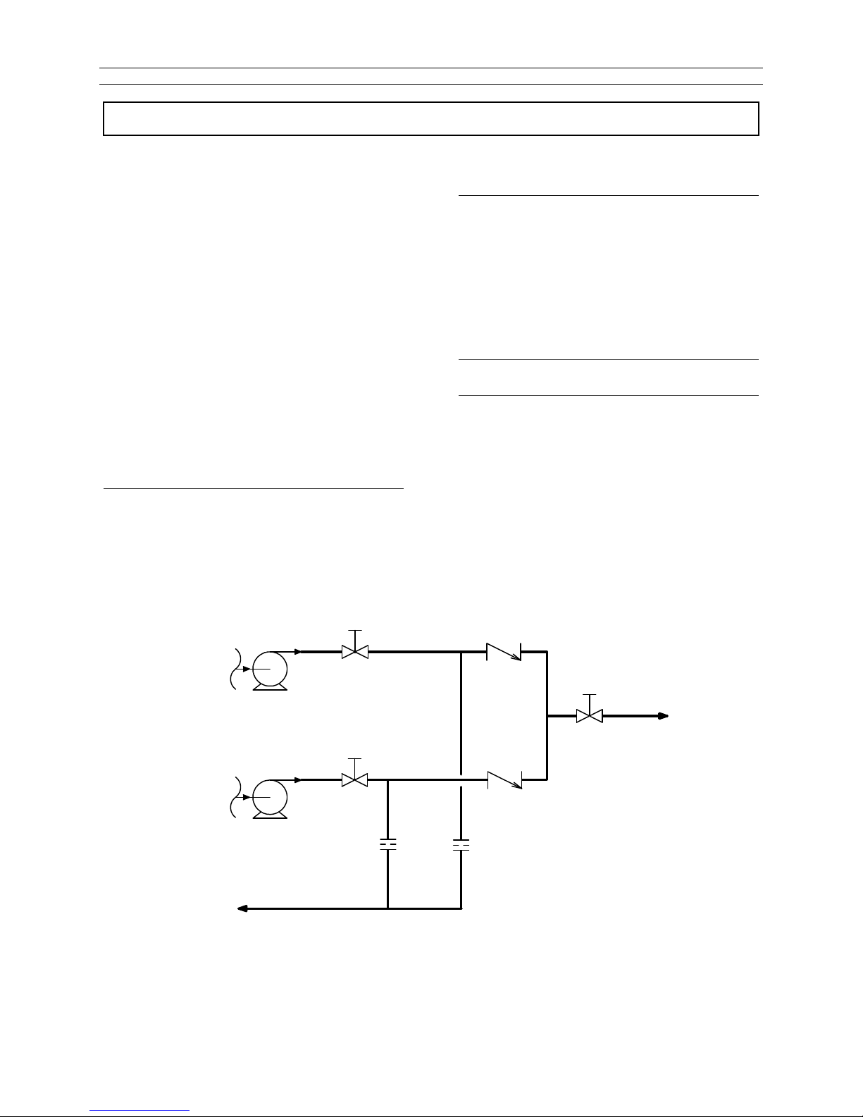
To prevent back-flow, place check valves in the
discharge piping of each pump.
Note: Sundyne recommends installing
separate bypass loops around each
Figure 14. Bypass System Example for Parallel Pump Operation
Note: Do not operate the pumps at their peak
Sundyne recommends that separate flow
controls be used on each pump to provide a
lower minimum flow range than is achieved by
pressure control.
pump for additional operational
flexibility.
1. Start the first unit as described in the
Single Operation instructions.
2. Start the second unit with the bypass
valve set to maintain the flow above
minimum flow.
3. Open the discharge valve on the second
unit so that the design flow of both units
is maintained.
head capability.
FROM
SUPPLY
TO
SUPPLY
TRIM
VALVES
CHECK
VALVES
THROTTLE
CONTROL
VALVE
BYPASS
ORIFICES
SA-07-11-92, Rev Orig 26 October 2015
Page 34
Instruction and Operation Manual
Suction Conditions
A
B
OPERATION & CONTROL
Operation of Sundyne Pumps
Under normal operation, several factors must be
taken into consideration to ensure successful
pump operation. Experienced pump operators
will be aware of jeopardizing factors and their
effects.
Improper flow of liquid into the impeller is the
most common operational abuse of centrifugal
pumps. Two conditions must exist to prevent
turbulence at the eye of the impeller.
Proper suction piping, see suction piping
section.
Liquid reaching the impeller eye must
have enough vapor pressure to prevent
the fluid from flashing to a gas in the
impeller. If this condition occurs, it will
cause cavitation, which can damage the
impeller and inducer. When centrifugal
pumps cavitate the noise sounds like the
pump is “pumping gravel”. In high speed,
single stage pumps, this sound may not
be discernable. Cavitation can be
prevented by maintaining suction pressure
at a high enough level and suction
temperatures low enough to maintain Net
Positive Suction Head (NPSHa) available
greater than Net Positive Suction Head
(NPSHr) required by the pumps.
noise, vibration, and damage to the pump,
primarily when a control valve is located an
excessive distance downstream from the pump.
Entrained Gases
The head and capacity of centrifugal pumps will
be reduced by gas that is drawn in with the
liquid. Under normal operating conditions,
centrifugal pumps can tolerate up to 2% of gas
(by volume). Entrained gases can cause
damage to mechanical seals with the exception
of double seals. If you have entrained gas,
contact Sundyne for further instruction.
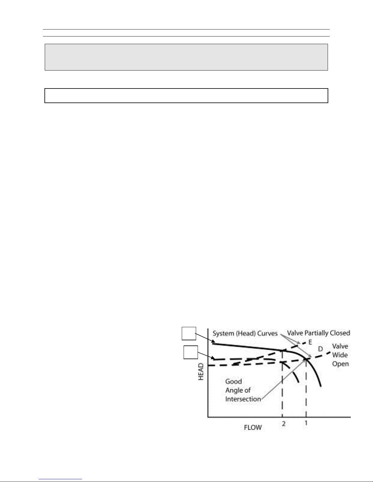
System Head Curve
The point of intersection between the system
curve and the pump characteristic curve
determines the flow or operation for the
centrifugal pump. For steady flow to occur, the
system curve must intersect the pump
characteristic curve at a significant angle. The
following diagram gives examples of satisfactory
and unsatisfactory angles of intersection.
Figure 15. Typical Operation
Minimum Flow Conditions
Vibration and noise will occur during operation of
centrifugal pumps if either of two conditions
exist:
Internal flow separations
Recirculation at low flow conditions
If the operator is noticing excessive noise or
vibration, operation must be suspended until the
cause is determined and corrected. Continued
use may cause damage to the pump.
Resonance in the discharge line can accentuate
SA-07-11-92, Rev Orig 27 October 2015
Page 35
Instruction and Operation Manual
Parallel Operation
Note: In Figure 15, the curve for pump A has
a significant angle of intersection with
system curves D and E. The system
curve D could represent a system with
the control valve wide open while curve
E could represent the same system but
with the throttle valve closed to reduce
flow from flow 1 to flow 2. Pump curve
B, on the other hand, will provide only
flow 2, even with the control valve wide
open (curve D). When the control valve
is partially closed to create system
curve E, the curve E and lower pump
curve B are practically parallel. The lack
of a significant angle of intersection
means that the system is unstable,
pump flow is likely to fluctuate
erratically and not respond to control
valve position.
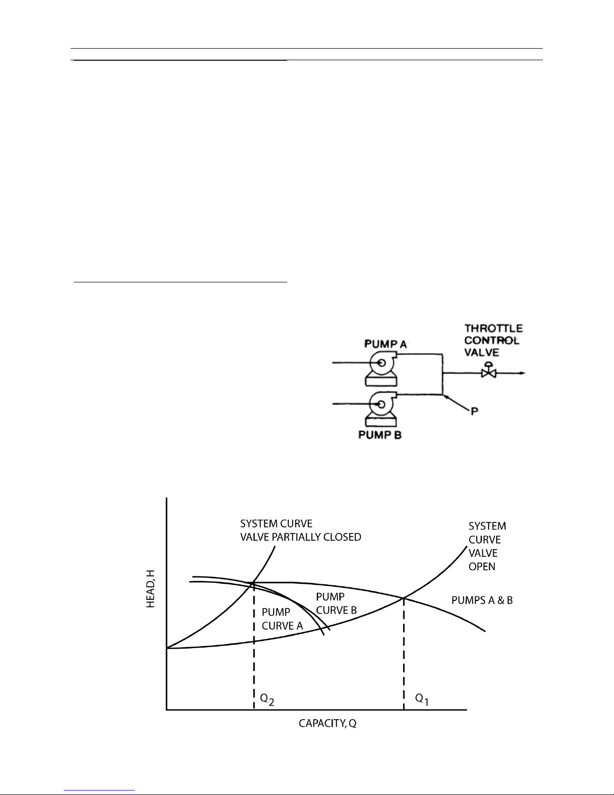
Maximizing control is critical when operating
centrifugal pumps in parallel. One pump can
overpower the other in regards to head at a
lower total flow. If a simple, unrestricted manifold
(Figure 16) connects two pumps at the
discharge head, the discharge head of one
pump is imposed on the other.
In Figure 17, two pumps operating in parallel will
never have exactly the same performance
curves. At the design point (Q1), with the valve
open, both pumps are operating at the same
flow and head. However, as the system curve
changes with the valve positioning (Q2), pump A
can produce a higher head than pump B. In this
case pump B will stop flowing altogether,
causing it to operate in an unstable minimum
flow condition.
Since pump B would effectively be deadheaded,
the fluid in it would heat up and boil. During
internal boiling, it could encounter liquid slugging
and probable damage to the pump. Proper
selection of a control system can prevent this
situation.
Figure 16. Parallel Units Common Valve
Figure 17. Parallel Operation
SA-07-11-92, Rev Orig 28 October 2015
Page 36

Instruction and Operation Manual
Servicing
Maintenance Schedule
The timing for maintenance of the
Sundyne/HMD Sealless pump is established
primarily by the liquid end bearing bush system.
The time span is longer than for a “canned
motor” pump because it has over four times the
bearing bush wear allowance. It will outlast
mechanical seals because it is more tolerant of
solids and because the pressure x surface
velocity (PV) values of the bearing bush system
are much lower than the PV values of seal faces
in the mechanical seal. Despite these
conservative design advantages, the bearing
bush system can develop some wear over a
period of time, depending on the application.
It is possible to avoid the effects of excessive
bearing bush wear by the use of planned
maintenance based on experience on the
particular application involved. This will avoid
breakdown situations arising due to unmonitored
Table 3
Pump Prefix Magnet Coupling
Size
wear causing pump failure by contact between
other rotating and stationary parts of the pump
liquid end. It is suggested that after initial
commissioning, the pump should be inspected
after six months to establish the future
maintenance periods by comparison of the
running clearances with the “as new”
dimensions.
Vibration Levels
An indication as to the condition of pump can be
ascertained by recording the vibration level of
the pump and comparing them to level that
would be expected when the unit is new. The
following table indicates typical levels of
vibration that can be expected during operation
at the conditions indicated on the pump
nameplate:-
4 Pole Speeds
mm/sec [in/sec] - rms
2 Pole Speeds
mm/sec [in/sec] - rms
LMV 801S EA 2.8 [.110] <3 [.118]
Breathing apparatus may also be
necessary.
Dismantling
Before starting to dismantle a pump all relevant
and appropriate safety precautions must be
taken, particularly if the pumps have been
handling hazardous or toxic liquids. Consult
CoSHH and Material Safety Data Sheets
(MSDS). IF YOU HAVE ANY DOUBTS, SEEK
ADVICE FROM YOUR SAFETY OFFICER OR
THE LIQUID MANUFACTURER.
Obey the following rules:
Always wear adequate Personal
Protective Equipment (PPE) when
dismantling pumps that have been used
to pump toxic or hazardous products.
This should comprise clothing, eye and
gloved hand protection as a minimum.
Always isolate the pump electrically
before dismantling. Ensure that the
electrical switch gear cannot be
operated whilst any work is being
carried out on the pump.
Always drain the pump casing of
product before removing the pump from
its associated pipework.
Flush out the pump casing and shroud
with a compatible flushing liquid and
drain away to a safe area.
Check with your process engineers to
see if any special decontamination
procedures have to be followed before
working on the pump.
SA-07-11-92, Rev Orig 29 October 2015
Page 37
Instruction and Operation Manual
All pumps returned to HMD for factory
servicing must be decontaminated and
labelled in accordance with the
Sundyne/HMD Return Material
Authorization (RMA) procedure.
Fault Finding
These safety precautions are to be taken in
addition to any formal safety procedures
specified by your Company and do not
supersede, change or absolve you form your
statutory duties under current Government
legislation. Our recommendations are based on
our current experience. If in doubt or you need
to know our latest recommendations – you must
contact Sundyne/HMD Sealless Pumps.
Flowcharts
This section is intended to highlight possible
pump problems caused by system design
inadequacies or incorrect operation.
Because the sealless pump impeller is not
coupled directly to the electric motor, it is
inherently quiet so that any increase in noise is a
good indication that there is a problem.
Should it be necessary to dismantle a pump,
please read through the dismantling instructions
carefully (see section Dismantling).
No special tools1are required to dismantle a
Sundyne/HMD Sealless Pump and no special
skills are required as the pump is simple in
design and robust in construction.
Refurbishing is by replacement and no attempt
should be made to repair pump components by
welding and re-machining.
Clearances between the rotating components in
the pump are comparatively large, so care must
be taken not to scrap components before
checking that the clearances are excessive.
In the event that the magnetic coupling is pulled
out of step, then the motor must be stopped
IMMEDIATELY because continuation of running
will damage the magnets.
For further information on fault symptoms,
causes and remedies consult the Fault Tree
flowcharts in the following pages. (Section Fault
Finding).
SA-07-11-92, Rev Orig 30 October 2015
Page 38
Flow Chart 1
HAND
CORRECT
IN-CORRECT
IMPOSSIBLE
NORMAL
LEAKAGE OF FOOT A
DEFICIENT
RING DAMAGED
TRAPPED
LIQUID LEVEL
EXPECTED
EXPECTED
DISCHARGE PRESSURE
GAUGE READING
Instruction and Operation Manual
PUMP FAILURE
CHECK THE
DIRECTION OF
ROTATION
ROTATION
PRIMING
VALVE
LEAKAGE FROM
SUCTION PIPING
GRADUALLY OPEN
DISCHARGE VALVE
PRIME
CHECK SHUT OFF
PRESSURE WITH
DISCHARGE VALVE
SHUT OFF
PRESSURE
NORMAL
PRIMING
CLOSED
ROTATION
CHANGE TWO OF THE
THREE PHASES
SHUT OFF PRESSURE
IMPELLER OR NECK
MAGNET COUPLING
PULLED OUT OF STEP
ROTATE BY
LIGHT
HEAVY
(LOCK)
RINGS WORN OR AIR
PRESSURE
EQUAL TO SHUT-
OFF PRESSURE
SYSTEM
HEAD TOO
HIGH
SUCTION
HEAD TOO
LOW
SA-07-11-92, Rev Orig 31 October 2015
DEFECTIVE
DISCHARGE
OR CHECK
VALVE NOT
OPENING
LOWER THAN
FOREIGN
MATTER
BUILD UP IN
SUCTION
PIPE OF
FOOT VALVE
FOREIGN
MATTER
BLOCKING
DISCHARGE
PIPE
IN SUCTION
VESSEL TOO
LOW
CAVITATION
DISCHARGE
SHARP FALL IN
OBSERVE THE SUCTION
IN
PIPE
HIGH
FRICTION
LOSS IN
SUCTION
PIPING
CONTACT
BETWEEN
OUTER
MAGNET
RING AND
SHROUD
FOREIGN
MATTER
BUILD UP IN
CASING OR
IMPELLER
CONTACT
BETWEEN
INNER
MAGNET
RING AND
SHROUND
HIGHER THAN
VAPOUR
PRESSURE
OF PUMPED
LIQUID HIGH
PUMP
BEARINGS
LOCKED DUE
TO BUILD UP
OR FOREIGN
MATTER
AIR BEING
SUCKED
FROM
SUCTION
LINE
FOREIGN
MATTER
BUILD UP IN
CASING OR
IMPELLER
CAVITATION
IN SUCTION
PIPE
Page 39
Instruction and Operation Manual
Flow
Chart
2
CORRECT
IN-CORRECT
TOO HIGH
LIQUID LEVEL
EXPECTED
E
XPECTED
PUMP FLOWRATE OR
HEAD DEFICIENCY
CHECK THE
DIRECTION OF
ROTATION
ROTATION
CHANGE TWO OF
THE THREE PHASES
SHUT-OFF
PRESSURE
DEFICIENT
IMPELLER OR NECK
RINGS WORN
AIR TRAPPED IN PUMP
ROTATION
CHECK SHUT-OFF
PRESSURE WITH
DISCHARGE VALVE
FULLY CLOSED
SHUT-OFF
PRESSURE
NORMAL
FULLY OPEN
DISCHARGE
VALVE
COMPARE
SPECIFIED VALUE
OF PUMPS WITH
READING OF GAUGE
IN OPERATION
RUNNING HEAD IS
HIGHER THAN
EXPECTED
SYSTEM HEAD IS
LOWER THAN
SUCTION
HEAD TOO
LOW
SA-07-11-92, Rev Orig 32 October 2015
FOREIGN
MATTER
BUILD UP IN
SUCTION
PIPE OF
FOOT VALVE
IN SUCTION
VESSEL TOO
LOW
HIGH
FRICTION
LOSS IN
SUCTION
PIPING
RUNNING HEAD IS
LOWER THAN
EXPECTED
OBSERVE THE
SUCTION GAUGE
READING
HIGHER THAN
FOREIGN
MATTER
BUILD UP IN
CASING OR
IMPELLER
VAPOUR
PRESSURE
OF PUMPED
LIQUID IS
HIGH
Page 40
Instruction and Operation Manual
CORRECT
IN-CORRECT
SPECIFIC GRAVITY OR
DAMAGED
AND REMOVE
BUILD UP IN P
UMP
Flow Chart 3
THE THREE PHASES
HEAVY RESISTANCE
ROTATED MANUALLY
ROTATION
CHANGE TWO OF
ABNORMAL
IS FELT WHEN
MOTOR CURRENT HIGH
VISCOSITY OF
PUMPED LIQUID IS
HIGH
CHECK THE
DIRECTION OF
ROTATION
ROTATION
MEASURE CURRENT
WITH DISCHARGE
VALVE FULLY
CLOSED
NORMAL
OVER RATE OF
FLOW
PUMP BEARINGS
DIS-
ASSEMBLE
AND
REPLACE
DEFECTIVE
PARTS
SA-07-11-92, Rev Orig 33 October 2015
MOTOR
ROTOR
DAMAGED
REQUIRING
NEW MOTOR
FOREIGN MATTER
DIS-
ASSEMBLE
FOREIGN
MATTER
ADJUST
RATE OF
FLOW
Page 41
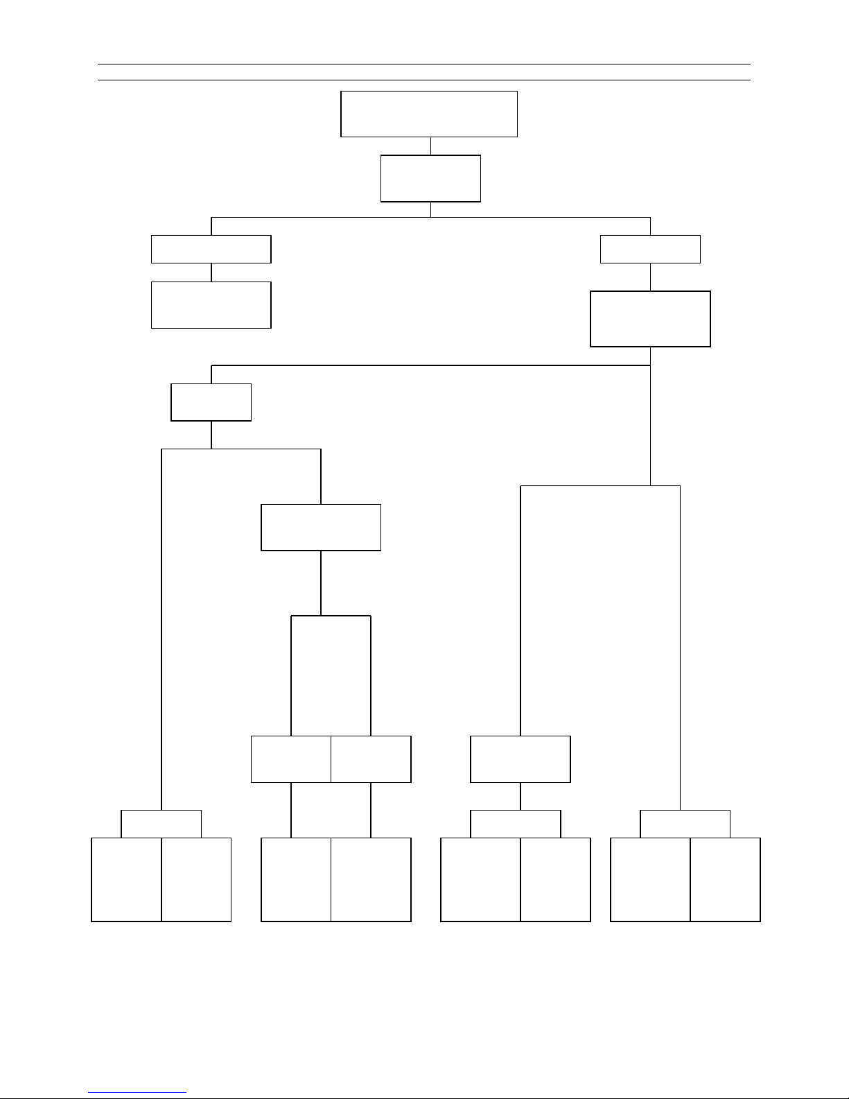
Instruction and Operation Manual
LOCATE SOURCE OF
ROTATION
CORRECT
IN-CORRECT
FOUNDATION OR
DRIVE SHAFT
Flow Chart 4
CHANGE TWO OF
THE THREE PHASES
ROTATION
INSIDE THE
PUMP
EXCESSIVE NOISE AND
VIBRATION
CHECK THE
DIRECTION OF
ROTATION
NOISE AND
VIBRATION
BEARINGS
DAMAGED
BEARINGS
WORN
CHECK THE
SUCTION GAUGE
READING
HIGHER
THAN
EXPECTED
FOREIGN
MATTER
BUILD UP
IN PUMP
LOWER
THAN
EXPECTED
CAVITATION WATER
RESONANCE
OF PUMP
FOUNDATION
FROM
PIPING
HAMMER
OUTER
MAGNET
RING NOT
SECURED TO
CORRECTLY
BEARINGS
WORN OR
COUPLING
MIS-
ALIGNED
SA-07-11-92, Rev Orig 34 October 2015
Page 42

Instruction and Operation Manual
Pump Diagnostics
Several system factors may affect the
performance of the pump. These factors are:
Temperature
Specific gravity
Suction pressure
Driver Speed
Control characteristics
These factors as well as internal problems must
be considered when analyzing pump system
performance. The following table gives
diagnostic information that can be useful when
analyzing gearbox and pump performance
problems
Flow rate
Table 4. Pump Diagnostics
Situation/Symptom Possible Cause Investigative/Corrective Action
No flow, no pressure at
start-up.
Pump not completely filled with liquid. Bleed all vapor or air from vent.
Allow more cool-down time if pumping low
temperature fluid.
Check suction line for air leak if suction
pressure is lower than atmospheric.
NPSH actually lower than NPSH requirement listed on
specification sheet.
Suction line blocked – check suction screen
and valve.
Excessive pressure drop through suction
piping.
Flow restricted by vapor pockets in high points
of suction line.
Suction tank level or pressure too low.
Entrained air or vapor in pumped fluid.
NPSH reduced by presence of more volatile
fluid in process fluid.
Failure of drive component, such as interconnecting
shaft or impeller key, or item missing from assembly.
Reverse direction of rotation.
Insufficient total head. Flow too high.
Wrong direction of driver shaft rotation. (It is possible
for the pump to develop greater than 50 percent
design total head in this condition).
NPSH actually lower than NPSH requirement listed on
specification sheet.
Flow too low, causing overheating of fluid resulting in
internal boiling and unstable pump operation.
Diffuser discharge throat partially plugged or
impeller damaged by passage of a solid particle.
SA-07-11-92, Rev Orig 35 October 2015
Disassemble and inspect.
Direction of driver shaft rotation must be as
shown by arrow on pump casing. Note: Impeller
and driver rotate in the same direction.
Check total head and flow rate against
performance curve.
Direction of driver shaft rotation must be as
shown by arrow on pump casing. Note: Impeller
and driver rotate in the same direction.
Refer to solutions listed under “No flow, no
pressure at start-up”.
Increase through-flow rate.
Bypass part of pump discharge to supply tank.
Clean these areas of all obstructions and restore
surfaces to a smooth polished finish free of all
corrosion pitting. Edge of diffuser throat must be
sharp.
Page 43

Instruction and Operation Manual
Remove fluid end and search for any mechanical
Situation/Symptom Possible Cause Investigative/Corrective Action
Insufficient total head
cont.
Driver overloaded.
Corrosion and/or erosion of diffuser throat (may
also be accompanied by corrosion/ erosion of
diffuser and cover surface adjacent to impeller).
Excessive recirculation from discharge to inlet. Check flow through external plumbing.
Process fluid specific gravity or viscosity different
from values shown on specification sheet.
Driver speed too low.
Pressure gauges or flow meters in error Calibrate instrumentation.
Fluid specific gravity or viscosity higher than values
listed on specification sheet.
Electrical failure in electric driver. Check circuit breaker heater size and setting.
If edge of throat is no longer sharp and smooth
or has opened in size, head-rise may be
reduced. Opening of the inlet area of the throat
will result in higher flow rate and horsepower
consumption. Corrosion/erosion of diffuser and
cover surfaces will result in a significant
horsepower increase.
Pump o-ring (936C) damaged or missing.
Integral centrifugal separator orifice worn.
Check actual viscosity and specific gravity at
operating temperature. Viscosity higher than five
centipoise will cause reduced head and flow and
increased power consumption.
Check speed against value listed on
specification sheet.
Check actual viscosity and specific gravity
against value listed on specification sheet.
Check voltage and voltage balance between
phases.
Current for each phase should be balanced
within three percent.
Excessive discharge
pressure pulsations.
Mechanical failure in driver or pump. Removedriver and check for freedom of rotation.
failure.
Corrosion pitting on surface of diffuser cover or
diffuser, adjacent to impeller blades. Head rise is
also reduced by this condition.
Flow rate too low.
Insufficient NPSH available.
Defective flow control valve. Check control valve.
Disassemble pump and inspect. Rough or
pitted surfaces can cause friction losses which
will significantly increase horsepower
consumption. Clean these areas of all
obstruction and restore surfaces to a smooth
polished finish. Check diffuser throat area at
the inlet; erosion or corrosion resulting in
roughness or increased area will increase
horsepower consumption. Note: A larger throat
size than design will allow a higher flow and
horsepower for a given head rise.
Increase flow rate through pump. Add bypass to
suction tank if necessary.
Refer to solution for insufficient NPSH under “No
flow, no pressure at startup,” above.
SA-07-11-92, Rev Orig 36 October 2015
Page 44

Instruction and Operation Manual
General Safety
Maintenance
Before disassembling a pump all relevant and appropriate safety precautions must be taken.
SEEK ADVICE FROM YOUR SAFETY REPRESENTATIVE OR THE MANUFACTURER IF YOU
HAVE ANY DOUBTS.
Care should be taken in assembling magnetic components due to their attraction with ferrous
materials. Also particular care should be exercised when inserting or withdrawing the Inner
Magnet Ring into or out of the Containment Shell contained within the Coupling Housing, due to
the axial pull of the Outer Magnet Ring.
SA-07-11-92, Rev Orig 37 October 2015
Page 45

Instruction and Operation Manual
Tools Required
The table of tools shown below is fully comprehensive and allows for complete strip-down and re-build of
pump.
Tool List
3/16”
7/32”
Hexagon Bit Socket
and / or
Hexagon Key
Socket
and / or
Spanner
¼”
5/16”
3/8”
½”
8 mm (IEC Motors)
¾” (Deep)
1-1/8” (Deep)
1-1/4”
50 mm
17 AF (IEC 90 Motor)
19 AF (IEC 100 to 132 Motor)
24 AF (IEC 160 to 225 Motor)
Torque Wrenches For torque settings from 25 Nm (18 lbf-ft) to 300Nm (220 lbf-ft)
General tools required
Ratchet
Extension bar
Soft mallet
Eye Bolts 5/16" x 3
Eye Bolt 1/2" UNC x 3
Eye Bolt 5/8” UNC x 2
Eye Bolt M16 x 2 (IEC Motors)
Lifting Equipment x 2
SA-07-11-92, Rev Orig 38 October 2015
Pry bar x 2
Dial Test Indicator complete with magnetic base
Loctite 242 Threadlocker (or similar)
Anti-seize compound
Steel Discs Ø3.50 X 1.0 thick [Ø90mm X 25 mm thick] x 2 (for
Replacement of Bushes and Thrust Pad)
Page 46
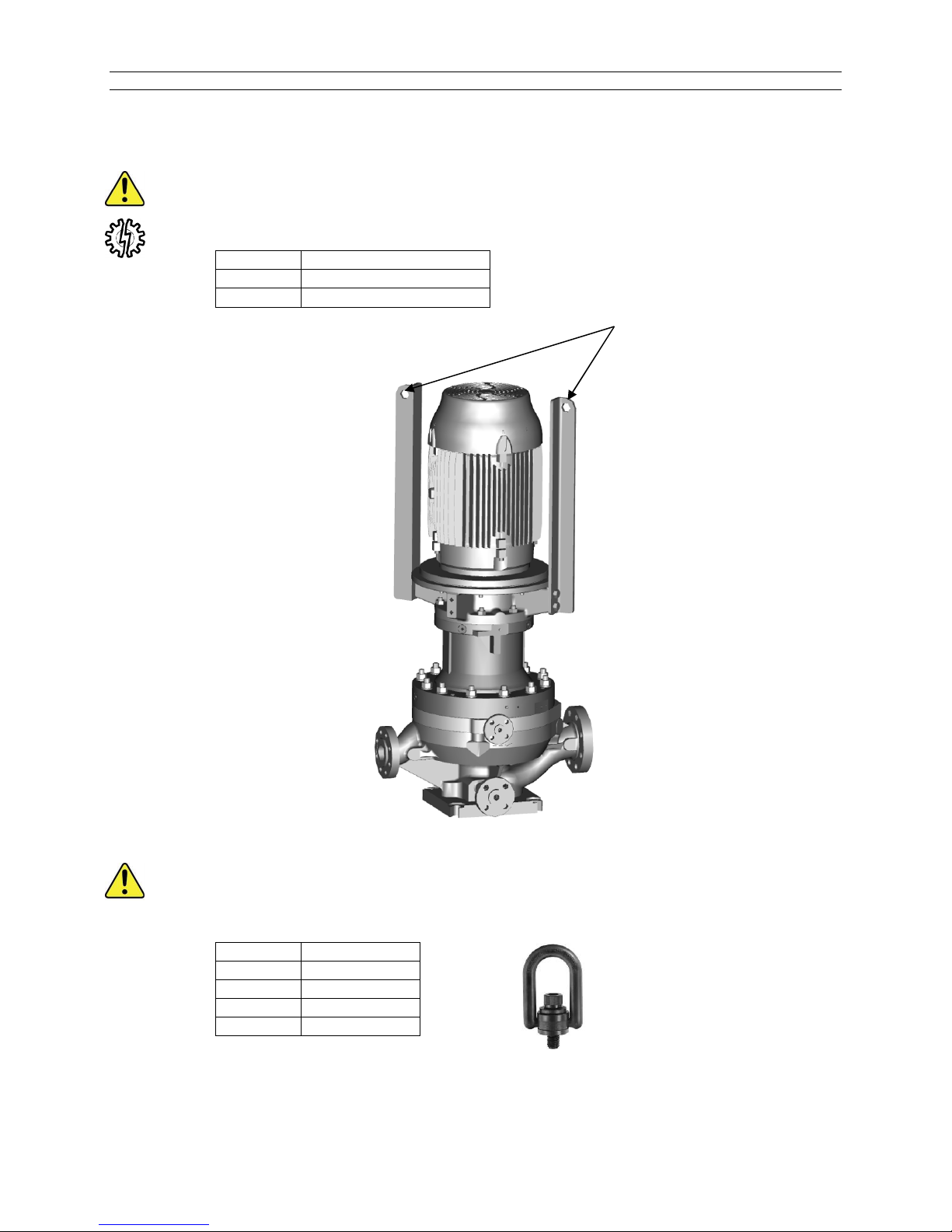
Quantity
Weight Capacity
Quantity
Size
Lifting
Points
Instruction and Operation Manual
Lifting Lugs are intended to lift the entire pump assembly. Never use the lifting lugs to stand a
pump up from a horizontal position. The lugs are intended for a vertical lifting direction only. Eye
bolts attached to the motor are intended for lifting the motor only.
2 Up to 1650 lbs (750 kg)
4 Over 1650 lbs (750 kg)
Lifting
Lugs
Sundyne recommends the use of swivel hoist rings for the handling of parts and assemblies as
demonstrated in the following section. Use of other lifting devices may result in harm to the user
or damage to equipment.
3 5/16-18
3 ½-13 UNC
2 5/8-11 UNC
SA-07-11-92, Rev Orig 39 October 2015
Swivel Hoist Ring
Page 47
DISASSEMBLY OF PUMP
Before working on Pump ensure it is drained and decontaminated.
When disassembling Pump, it is recommended that each set of fasteners be individually bagged.
Tie a tag to each bag with fastener Reference number (REF) written on tag. Reference numbers are
taken from the Cross Sectional Drawing and Parts List, and are contained in brackets ( ) in this
manual. This will aid rebuilding, particularly where fasteners for different components are of similar
size. Work should be carried out in a clean area where possible.
For maintenance purposes the pump casing may be left in the pipework whilst the main part of the
pump is back-pulled, OR the complete pump can be removed from the pipework.
Maintenance work should be carried out in a workshop or suitable work area.
The pump can be split into three discrete assemblies for maintenance purposes:
Motor and Motor Support
Magnet Drive Unit
Casing and Diffuser
These will be considered at different stages in the instructions below.
If the complete pump is to be removed from the pipe work and taken to a working area, the pump
case must be bolted down to a suitable base for stability before work on the pump can begin.
This is especially important for larger motors and pumps with a bearing box fitted.
The Inner Magnet Ring (37.37) and Outer Magnet Ring (51.51) contain strong magnets and care
should be taken in the vicinity of ferrous materials.
For example, if workbench top is metal, ensure it has a covering of hardboard, plywood, or plastic
sheeting. Also be careful when using tools around these components.
Note that two cranes or lifting devices will be required to maneuver the pump parts into position for
maintenance.
SA-07-11-92, Rev Orig 40 October 2015
Page 48
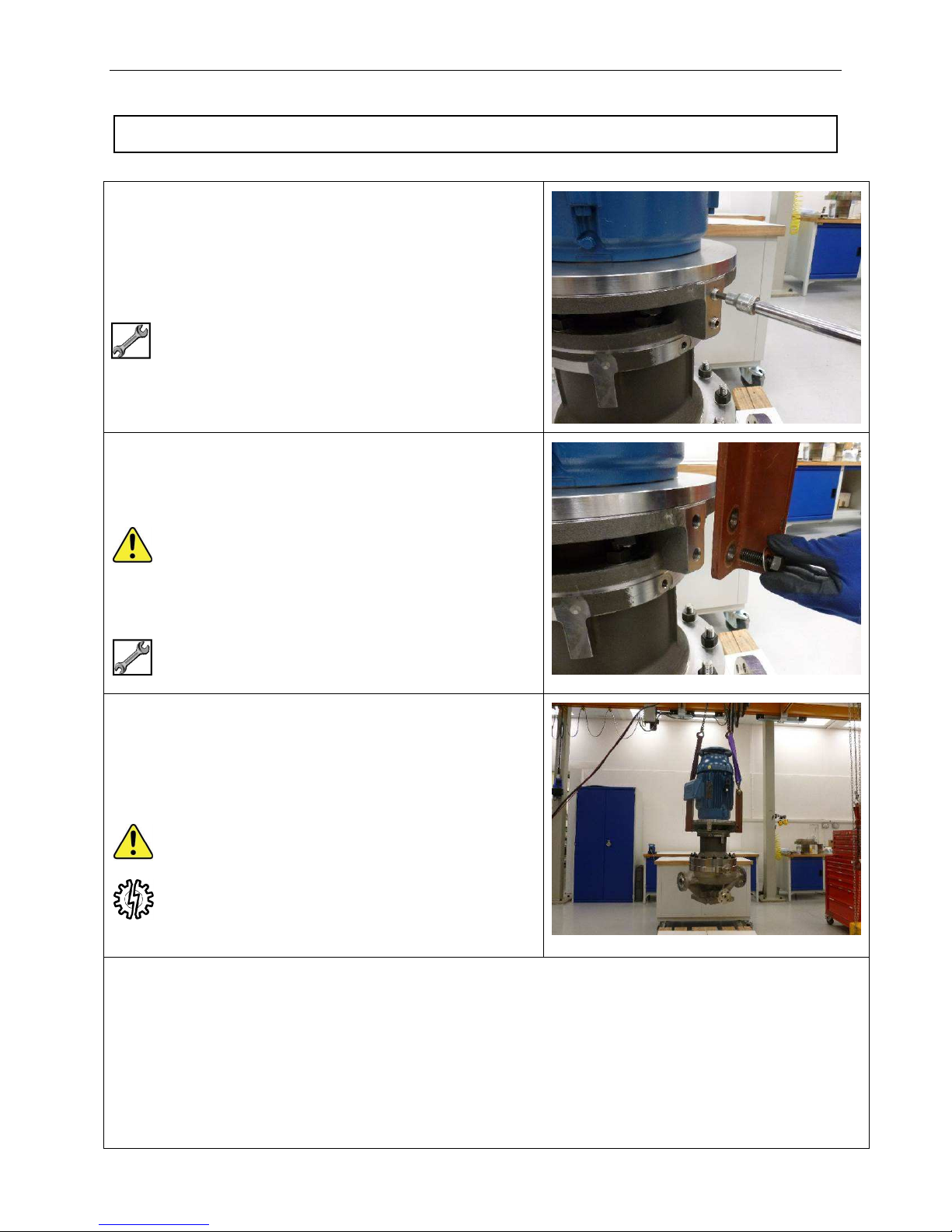
Disassembly Stage 1 – Removal of Pump from Pipe Work
Disassembly - Stage 1 -Removal of Pump from Pipe Work
1.01 Complete pump should be lifted with Lifting Lugs
(98.98) that were originally supplied with the pump.
To fit Lifting Lugs first remove grub screws (45.S53)
from webs of Motor Adaptor (45.45).
5/16” Hex
1.02 Fit Lifting Lugs (98.98) to Motor Adaptor (45.45) with
High Tensile Retention Screws (98.S11) and
Washers (98.W11).
Each new pump is furnished with the above lifting
equipment.
2 off Lifting Lugs for pumps up to 750 kg (1650 lbs).
4 off Lifting Lugs for pumps over 750 kg (1650 lbs).
15/16” AF for NEMA motors
24 mm AF for IEC motors
1.03 Fit suitable lifting gear to Lifting Lugs (98.98) and
take up any slack to prevent toppling of pump.
Undo pipe work and fixing down screws.
Lift pump away from pipe work and move to
suitable working area.
Securely fasten pump to suitable base during
transport.
It is recommended that the pump base be securely fastened to a suitable surface during maintenance
This is especially important when large motors are fitted.
SA-07-11-92, Rev Orig 41 October 2015
activities to prevent toppling of the pump.
Page 49
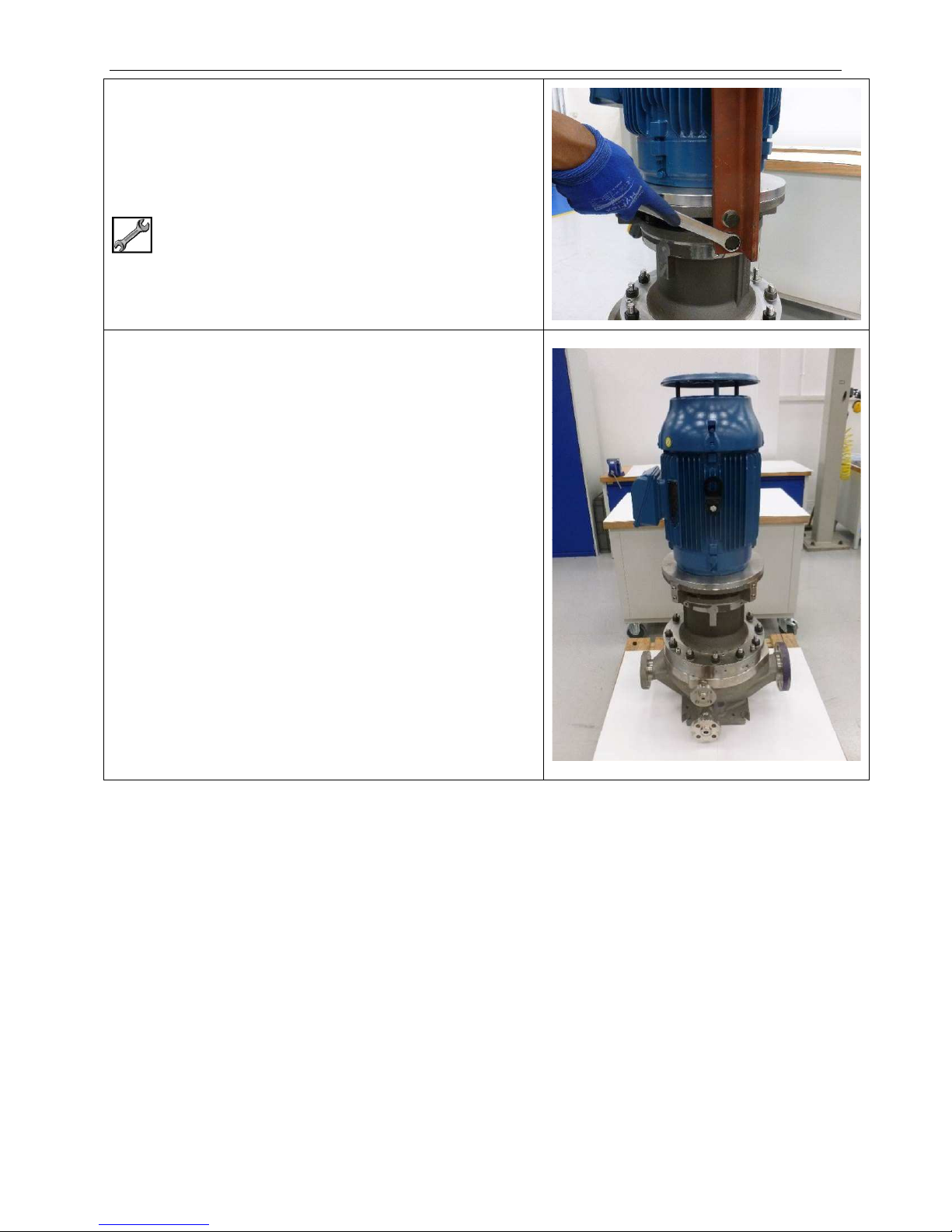
Disassembly Stage 1 – Removal of Pump from Pipe Work
1.04 Remove Retention Screws (98.S11), Washers
(98.W11) and Lifting Lugs (98.98) from Motor
Adaptor (45.45).
15/16” AF for NEMA motors
24 mm AF for IEC motors
1.05 Image shows a complete pump ready for
disassembly.
SA-07-11-92, Rev Orig 42 October 2015
Page 50
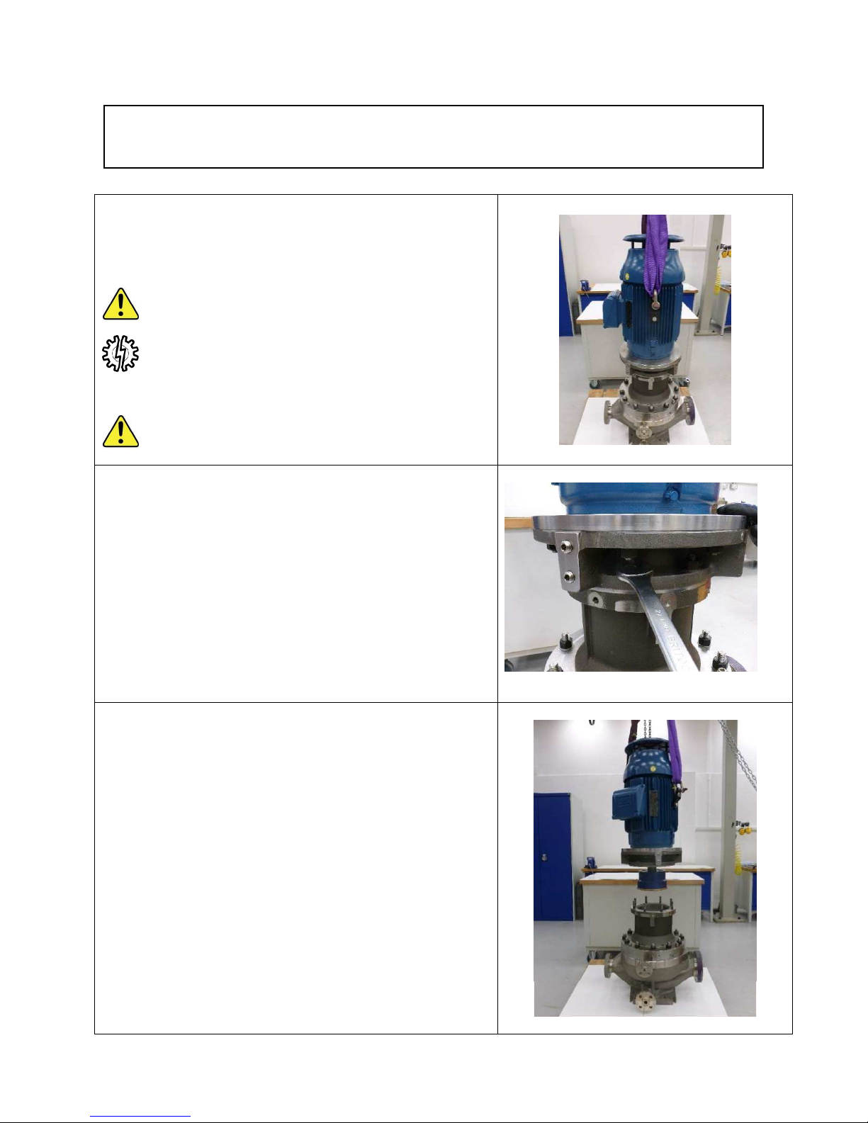
Disassembly - Stage 2 - Motor and Motor Support (Close
Coupled)
2.01 Attach suitable lifting gear to lifting eyes either side
Electric Motor
Ensure motor lifting eyes are capable of lifting the
additional weight of Motor Adaptor (45.45), Drive
Adaptor (52.52) and Outer Magnet Ring (51.51).
This extra weight is shown as Motor Adaptor weight
on customer specific installation drawing.
DO NOT LIFT COMPLETE PUMP WITH LIFTING
EYES OF ELECTRIC MOTOR.
2.02 Loosen and remove Nuts (43.N13) and Washers
(43.W14) from Motor Adaptor (45.45).
2.03 Lift Motor together with Motor Adaptor (45.45),
Drive Adaptor (52.52) and Outer Magnet Ring
(51.51) away from pump.
Note that Outer Magnet Ring (51.51) will be
attached to motor shaft via the Drive Adaptor
(54.54)
Allow the Outer Magnet Ring to be withdrawn
squarely from the Coupling Housing (43.43).
SA-07-11-92, Rev Orig 43 October 2015
Page 51
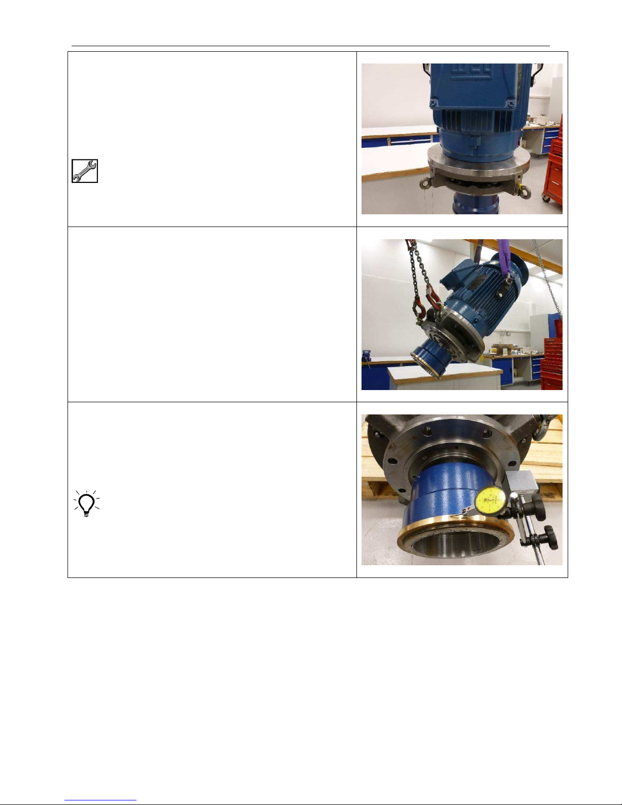
Disassembly – Stage 2 – Motor and Motor Support
2.04 Fit 2 off Eye Bolts to tapped holes in webs of Motor
Adaptor (45.45).
These Eye Bolts should be positioned in between
the Lifting Eyes of electric motor and on the same
side as the motor terminal box.
5/16” Eye Bolts for NEMA Motors
M16 Eye Bolts for IEC Motors
2.05 Use a second lifting device and attach lifting gear to
eye bolts on Motor Adaptor (45.45).
Lift motor assembly into a horizontal position.
Lower assembly onto a wooden pallet or similar so
that motor is resting on pallet whilst Motor Adaptor
overhangs the edge by a minimal amount.
2.06 There is no need to dismantle the assembly
further unless inspection or replacement of
parts is required.
Move to Stage 3 if assembly is in good order.
A run-out check of the Outer Magnet Ring (51.51)
should be performed to ensure it is within limits.
Set magnetic base on mounting face of Motor
Adaptor (45.45) and check run-out of bump ring with
Dial Test Indicator.
Maximum allowable run-out is 0.25 mm (0.010”)
SA-07-11-92, Rev Orig 44 October 2015
Page 52
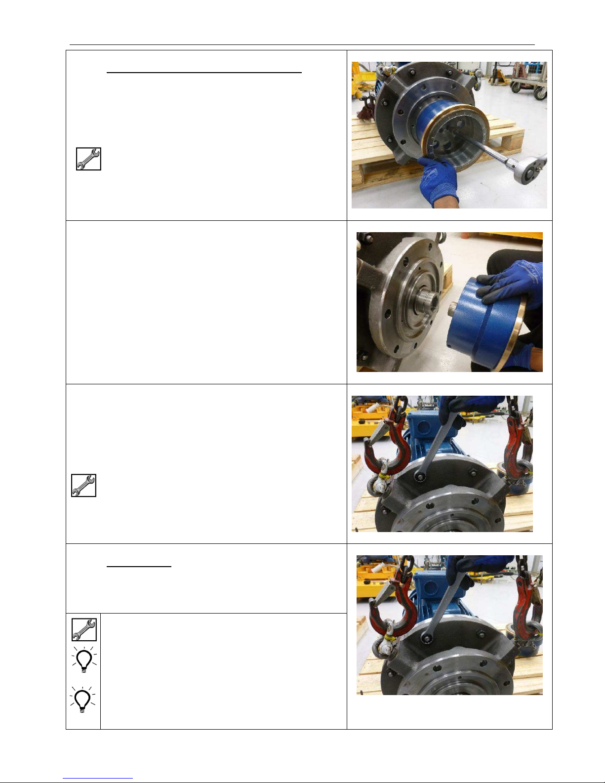
Disassembly – Stage 2 – Motor and Motor Support
2.07 To dismantle the assembly further if required
Loosen and remove 2 off Screws (52.S41) holding
Outer Magnet Ring (51.51) to Drive Adaptor
(52.52).
¼” Hex
2.08 Pull Outer Magnet Ring (51.51) from location in
Drive Adaptor (52.52).
2.09 Fit 2 off Eye Bolts and suitable lifting gear to
tapped holes in webs of Motor Adaptor (45.45).
5/8” Eye Bolts for NEMA motors
M16 Eye Bolts for IEC motors
2.10 NEMA Motors
Loosen and remove Nuts (45.N15) and Washers
(45.W15) that retain Motor Adaptor (45.45) to
Adaptor Plate (45.16).
¾” AF for NEMA motors
Hexagon Head Set Screws are used instead of
Studs, Nuts and Washers for smallest NEMA
Motors.
Fasteners may be either top side or under side of
Adaptor Plate, depending on motor size.
SA-07-11-92, Rev Orig 45 October 2015
Page 53
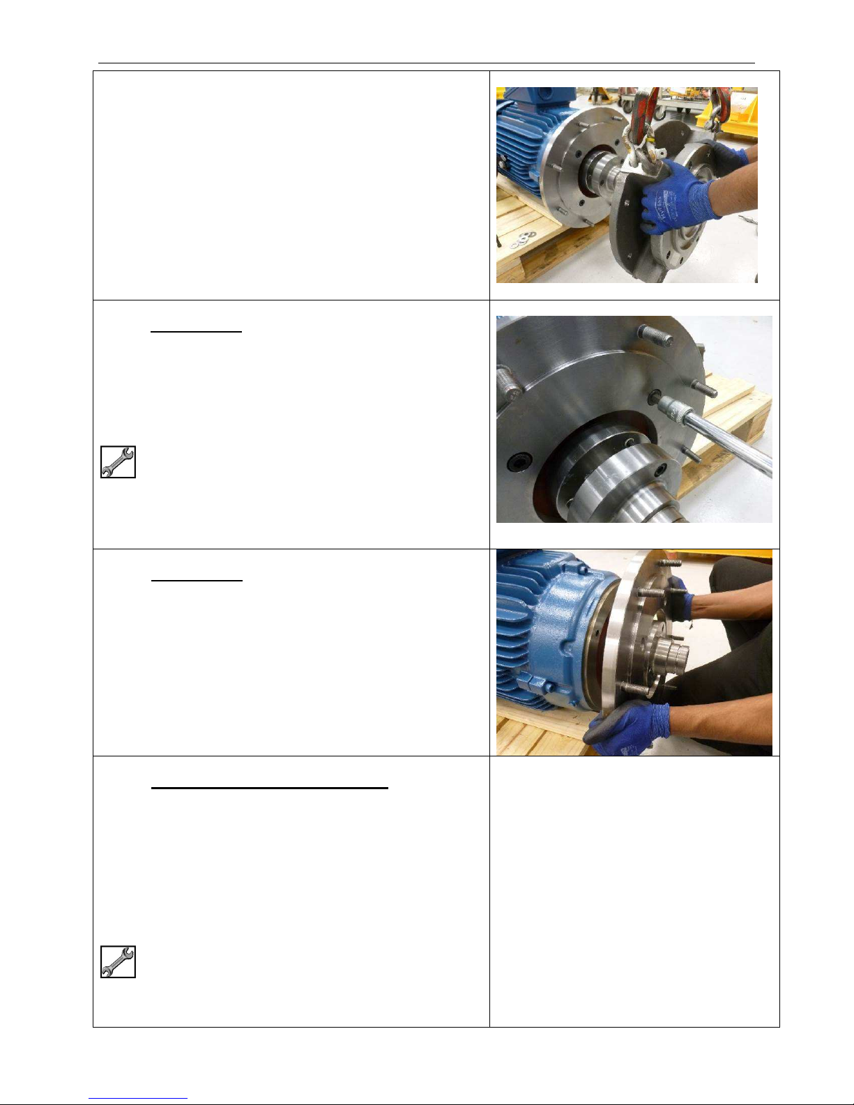
2.11 NEMA Motors
Remove Motor Adaptor (45.45) from Adaptor Plate
(45.16).
2.12 NEMA Motors
NEMA motors are face mounted, an Adaptor Plate
(45.16) will always be mounted to the front face of
the NEMA motor.
To remove the Adaptor Plate loosen and remove
Cap Screws (45.S42).
143TC to 145TC - 5/16” Hex
Disassembly – Stage 2 – Motor and Motor Support
182TC to 286TSC – 3/8” Hex
324TC to 365TSC – ½” Hex
2.13 NEMA Motors
Remove Adaptor Plate (45.16) from front face of
Motor.
2.14 IEC Motors WITHOUT Adaptor Plate
IEC motors are flange mounted, in most cases an
Adaptor Plate will not be required.
Loosen and remove Screws (45.S42) and Washers
(45.W15) that retain Motor Adaptor (45.45) to
motor.
Frame 225 2 pole motor will also require removal of
Nuts (45.N15) and Washers (45.W15).
Image not available
90 Frame – 17 mm AF
100 to 132 Frame – 19 mm AF
160 to 225 Frame – 24 mm AF
SA-07-11-92, Rev Orig 46 October 2015
Page 54
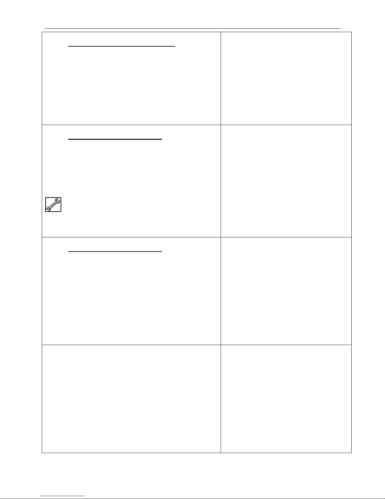
Disassembly – Stage 2 – Motor and Motor Support
2.15 IEC Motors WITHOUT Adaptor Plate
Remove Motor Adaptor (45.45) from Motor.
2.16 IEC Motors WITH Adaptor Plate
A separate Adaptor Plate (45.16) is only required
for the largest motors.
Loosen and remove Nuts (45.N15) and Washers
(45.W15) that retain Motor Adaptor (45.45) to
Adaptor Plate (45.16).
15/16” AF
Image not available
Image not available
2.17 IEC Motors WITH Adaptor Plate
Remove Motor Adaptor (45.45) from Adaptor Plate
(45.16).
2.18 IEC Motors WITH Adaptor Plate
Loosen and remove Screws (45.S42) and Washers
(45.W15) that retain Adaptor Plate (45.16) to Motor.
Image not available
Image not available
SA-07-11-92, Rev Orig 47 October 2015
Page 55

Disassembly – Stage 2 – Motor and Motor Support
2.19 IEC Motors WITH Adaptor Plate
Remove Adaptor Plate (45.16) from Motor.
Image not available
SA-07-11-92, Rev Orig 48 October 2015
Page 56
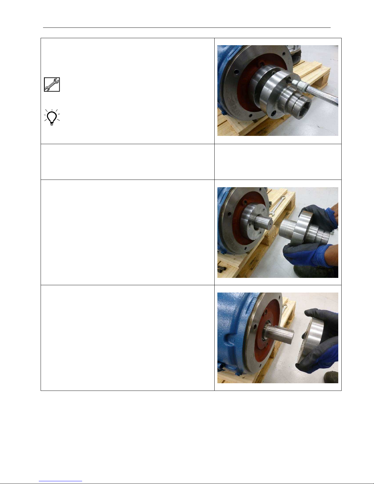
Disassembly – Stage 2 – Motor and Motor Support
2.20 Remove Draw Screws (52.S42) from Drive
Adaptor (52.52).
IEC Motors – 8 mm Hex
NEMA 143TC to 215TC – 7/32” Hex
NEMA 254TC to 365TSC – 5/16” Hex
A large screw driver or similar tool can be used
behind the flange between one of the screws and
the Drive Adaptor body to prevent the Drive Adaptor
from turning.
2.21 Fit removed Draw Screws (52.S42) into tapped
holes in front face of Drive Adaptor (52.52) and
tighten down onto taper ring to push ring free from
taper.
2.22 Once taper ring has been loosened the Drive
Adaptor (52.52) can be pulled free from the motor
shaft.
Image not available
2.23 Finally, remove taper ring from motor shaft.
SA-07-11-92, Rev Orig 49 October 2015
Page 57
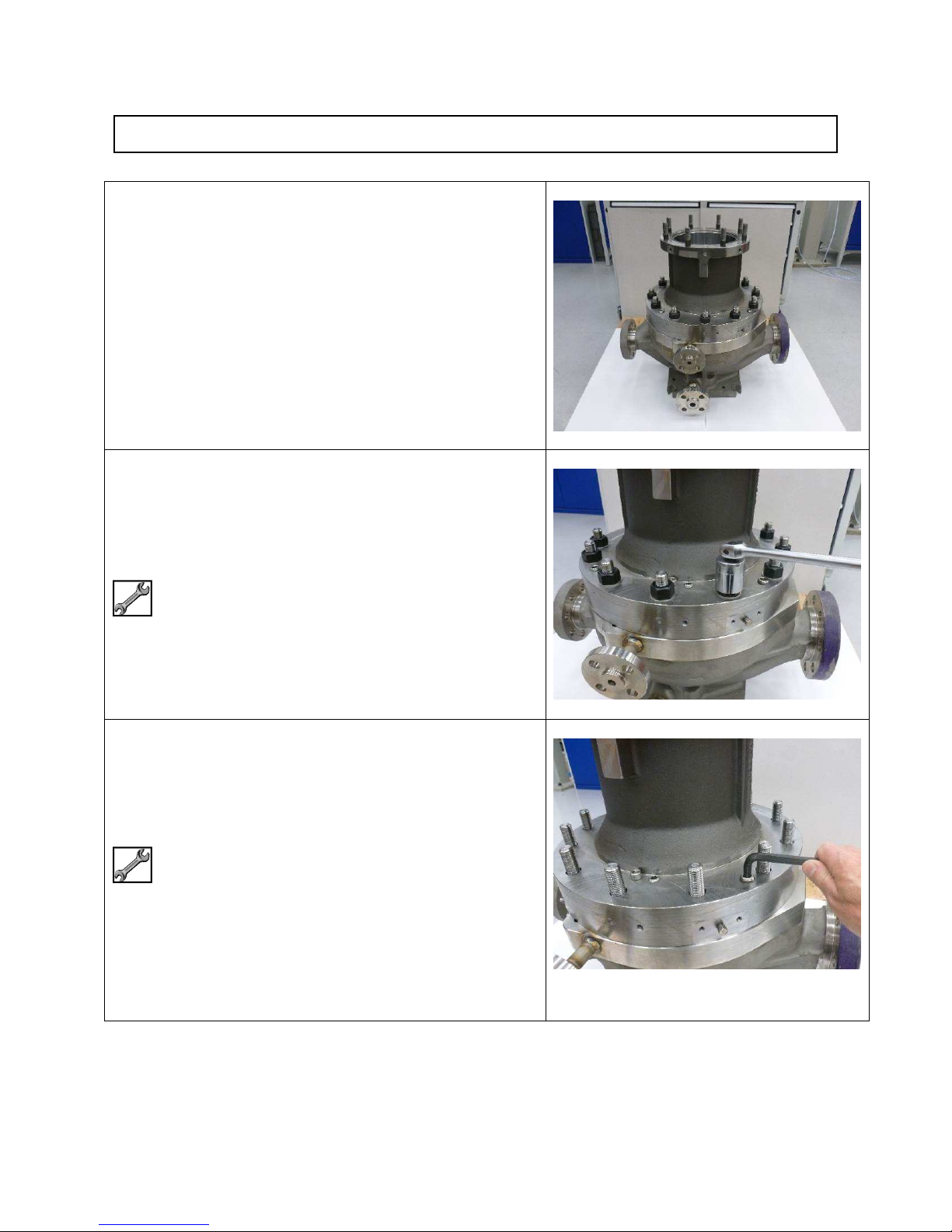
Disassembly - Stage 3 – Magnet Drive Unit
3.01 The image shows Magnet Drive Unit mounted to
pump Casing (41.41).
The next stage is to work on the Magnet Drive Unit
so first it must be removed from the pump Casing.
3.02 Loosen and remove 12 off Nuts (41.N11) and
Washers (41.W11).
1-1/4” AF
3.03 3 off Jacking Screws (43.S12) are provided in the
Coupling Housing (43.43) if required.
3/8” Hex
SA-07-11-92, Rev Orig 50 October 2015
Page 58
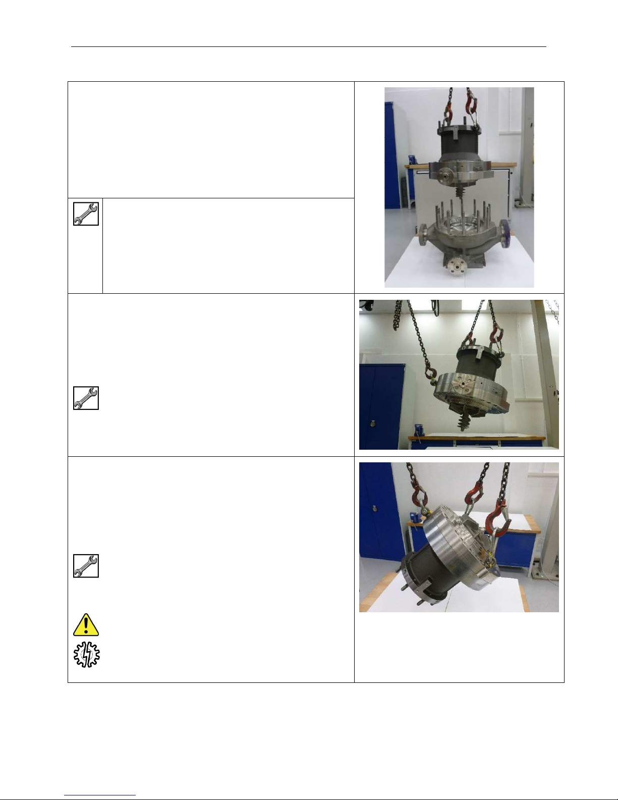
Disassembly – Stage 3 – Magnet Drive Unit
3.04 Fit 2 off Eye Bolts to tapped holes in outside of top
flange of Coupling Housing (43.43)
Attach suitable lifting gear to Eye Bolts and
withdraw Magnet Drive Unit from pump Casing
(41.41).
(Image shows optional inducer fitted to impeller)
½” Eye Bolt
3.05 Fit 1 off Eye Bolt to tapped hole in outside of bottom
flange of Coupling Housing (43.43.
Use a second lifting device to raise the Magnet
Drive Unit into a horizontal position.
(Image shows optional inducer fitted to impeller)
½” Eye Bolt
3.06 Remove 2 off Jacking Screws (16.S51) from
Adaptor Ring (16.16) and replace with 2 off Eye
Bolts.
Lift front of Magnet Drive Unit into the vertical
position and set down on a suitable working
surface.
2 x Eye Bolts 5/8”
CAUTION – Assembly is stable but top heavy
SA-07-11-92, Rev Orig 51 October 2015
Page 59
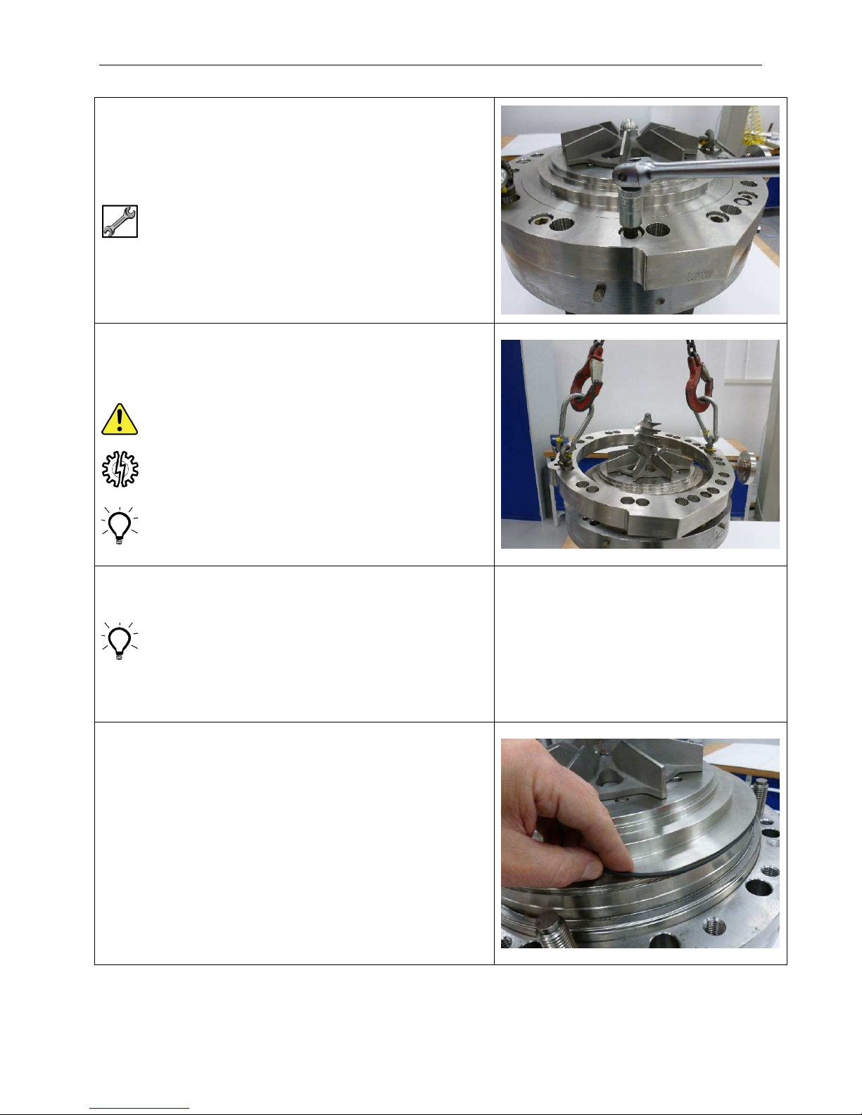
Disassembly – Stage 3 – Magnet Drive Unit
3.07 Remove 12 off Cap Screws (43.S55) from Adaptor
Ring (16.16).
5/16” Hexagon
3.08 Lift away Adaptor Ring (16.16).
Lifting gear can be used BUT be careful not to
topple unit if ring is reluctant to become free.
Alternatively remove Eye Bolts and re-fit Jacking
Screws (16.S51), Adaptor Ring may be lifted by
hand after jacking free.
3.09 Remove O-ring (14.OR2) from front shoulder of
Casing Plate (14.14) and discard.
O-ring may have been left in Diffuser (33.33) when
Magnet Drive was lifted from Casing (41.41).
Find O-ring and discard.
3.10 Remove O-ring (14.OR3) from groove in outside
diameter of Casing Plate (14.14) and discard.
SA-07-11-92, Rev Orig 52 October 2015
Page 60
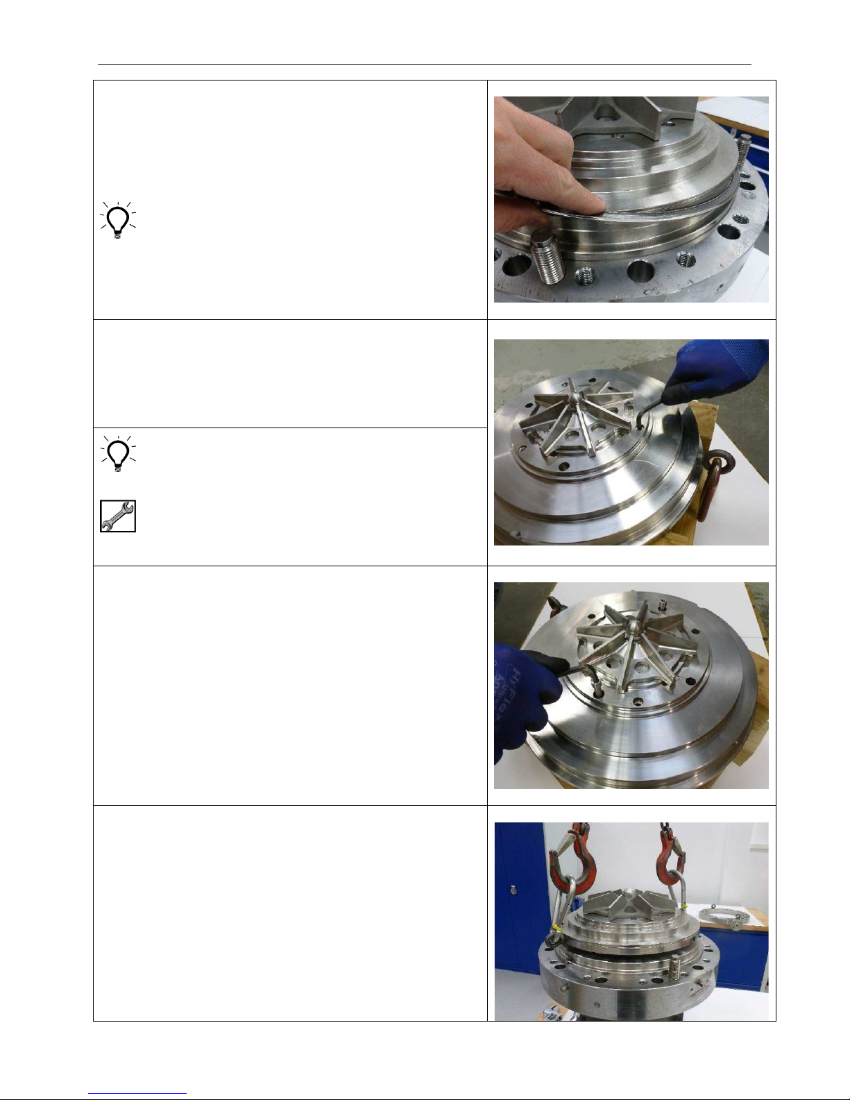
Disassembly – Stage 3 – Magnet Drive Unit
3.11 Remove Gasket (20.17) from shoulder of
Containment Shell (20.20) and discard.
Gasket may have been left in Adaptor Ring (16.16).
Find Gasket and discard.
3-12 Remove 3 off Cap Screws (20.S41) from Casing
Plate (14.14).
Some sizes of Impeller (06.06) may cover or partly
cover Screws. If this is the case, remove Impeller to
access the Screws and then replace but do not fully
tighten (see later for Impeller removal)
7/32" or 1/4" Hex
3.13 If required, fit 2 off Screws removed from Casing
Plate (14.14) into recessed tapped holes in face of
Casing Plate in order to jack Casing Plate free from
Containment Shell (20.20).
3.14 Fit 2 off Eye Bolts to tapped holes in outside
diameter of Casing Plate (14.14).
Lift Casing Plate (14.14) complete with rotating
assembly away from Containment Shell (20.20)
SA-07-11-92, Rev Orig 53 October 2015
Page 61
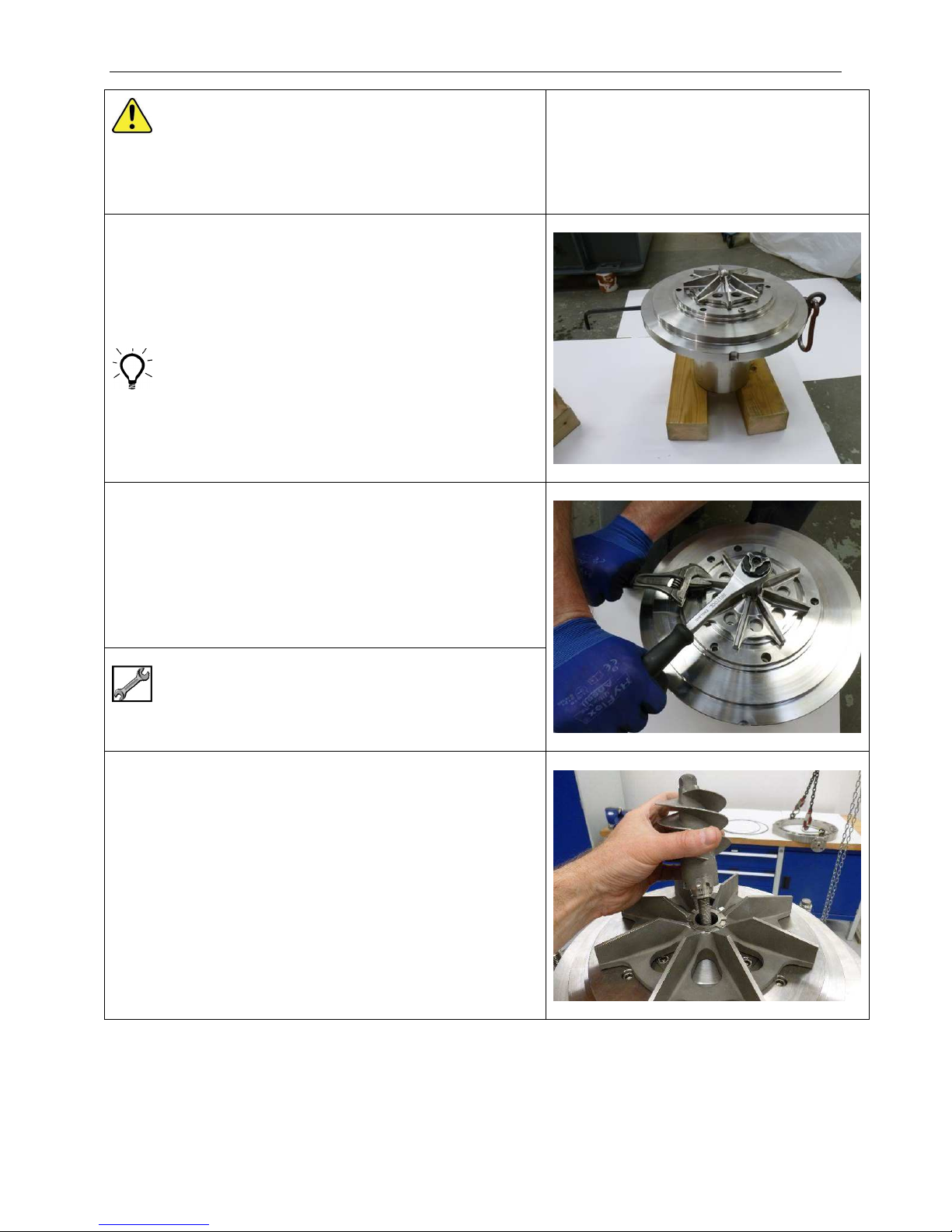
Disassembly – Stage 3 – Magnet Drive Unit
CAUTION - strong magnetic attraction of ferrous
objects to Inner Magnet Ring.
3.15 Stand assembly upright on the Inner Magnet Ring
(37.37) with impeller (06.06) uppermost.
For ZeroLoss Containment Shell the Inner Magnet
Ring (37.37) has a protruding nut and must be
supported either side of the nut.
3.16 Turn down tab of Impeller Tab Washer (02.05A).
Loosen Impeller Fastener (02.03) and remove.
LEFT HAND THREAD
Loosen in a CLOCKWISE direction
3/4" (Narrow Line Impellers)
1-1/8" (Wide Line Impellers)
3.17 Occasionally an Inducer (76.01) will take the place
of the Impeller Fastener.
An Inducer will be connected to the Pump Shaft
(02.02) with an Inducer Stud (02.48A).
Turn down tab of Tab Washer (02.05A).
Loosen Inducer with hexagon provided on nose of
Inducer and remove.
Inducer Stud may come away with Inducer or
remain in Pump Shaft.
SA-07-11-92, Rev Orig 54 October 2015
Page 62
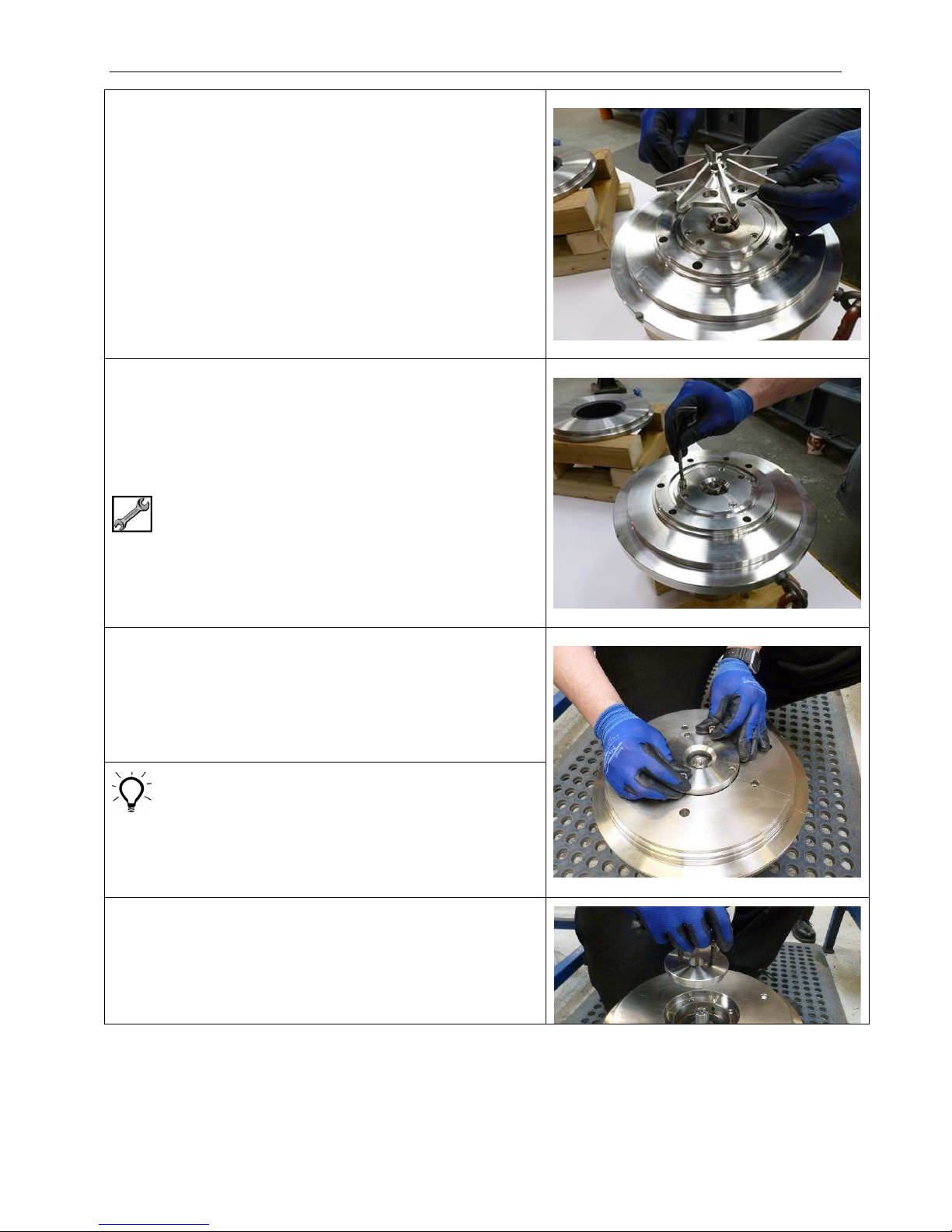
Disassembly – Stage 3 – Magnet Drive Unit
3.18 Remove Tab Washer (02.05A) and Impeller (06.06)
from Pump Shaft (02.02).
3.19 Remove 3 off Screws (14.S45) from Casing Plate
Cover (14.40).
7/32" or 1/4" Hex
3.20 Fit 2 off Screws (14.S45) to recessed tapped holes
provided and lift away Casing Plate Cover (14.40).
Screws (14.S45) can also be used to jack Casing
Plate Cover if required.
3.21 Fit 2 off Screws (14.S45) from Casing Plate Cover
to tapped holes provided in back of Thrust Washer
Holder (07.07).
Lift Thrust Washer Holder away from Pump Shaft
(02.02)
SA-07-11-92, Rev Orig 55 October 2015
Page 63

Disassembly – Stage 3 – Magnet Drive Unit
Note that Front Thrust Washer (07.07A) is located
in back of Thrust Washer Holder (07.07) and may
drop out of its location when the Thrust Washer
Holder is removed.
Care must be taken to avoid damage to Thrust
Washer which is made of Silicon Carbide.
SA-07-11-92, Rev Orig 56 October 2015
Page 64
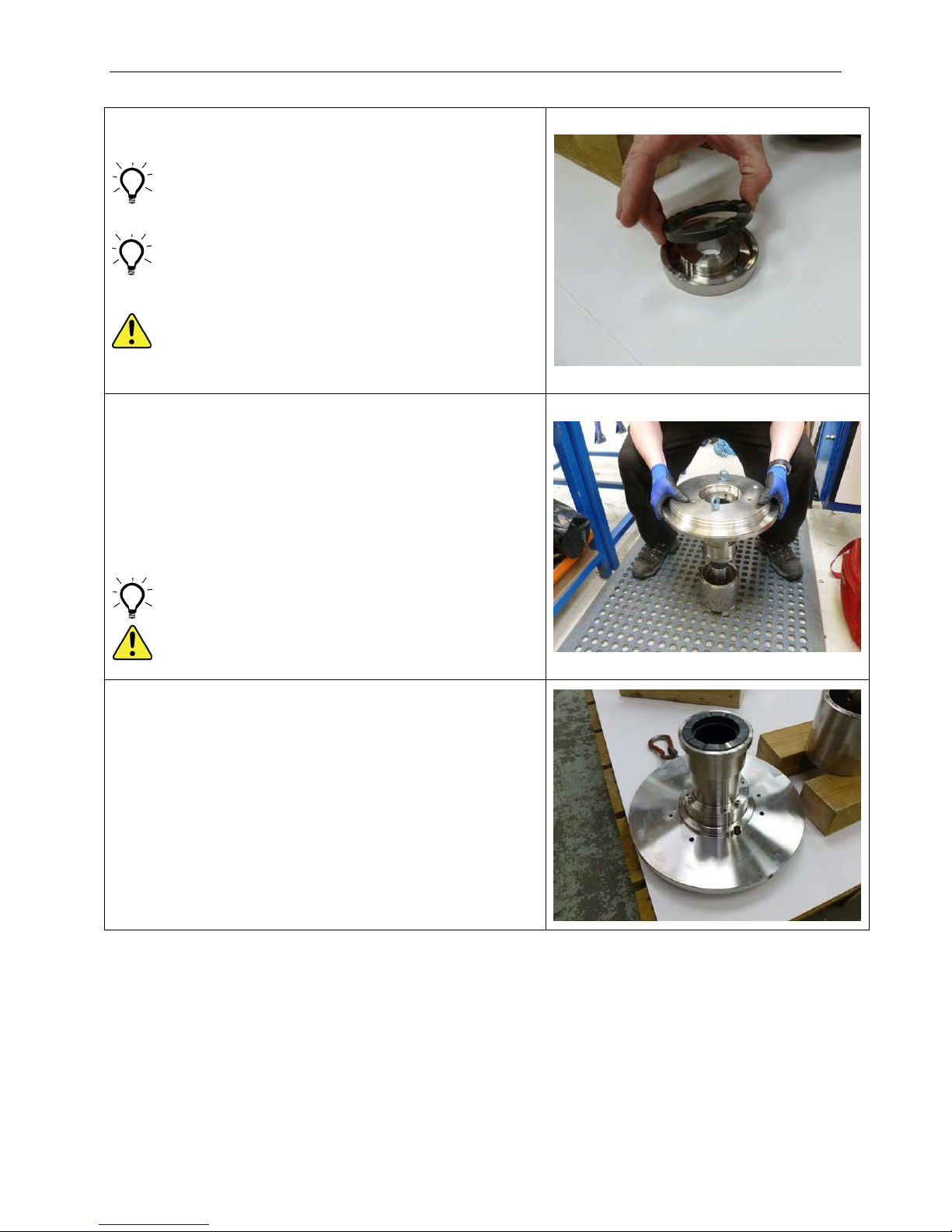
Disassembly – Stage 3 – Magnet Drive Unit
3.22 Remove Front Thrust Washer (07.07A) from its
location in Thrust Washer Holder (07.07).
Note that if Thrust Washer (07.07A) is in good
condition it can be left in place in the Thrust Washer
Holder (07.07).
If Thrust Washer is difficult to remove, use
compressed air or decontamination bath to loosen
solidified product. In extreme cases it may have to
be broken into pieces with hammer and punch.
Wear correct protective clothing, including overalls,
gloves, safety glasses or face shield. Ensure
location groove is clean and free from burrs, dents
etc. before inserting new Front Thrust Washer.
3.23 Very carefully lift Casing Plate (14.14) together with
attached Bush Holder (09.09) away from Pump
Shaft (02.02) and Inner Magnet Ring (37.37).
Extreme care must be taken not to damage Silicon
Carbide bearings.
Note that occasionally the rear Thrust Washer
(37.12) may be wrung together and come away with
rear Thrust Pad (09.13).
To help lifting by hand, hold Eye Bolts fitted either
side of Casing Plate.
Casing Plate with attached Bush Holder can weigh
more than 25kg (55 lbs).
3.24 Position Casing Plate (14.14) face down on the
bench with Bush Holder (09.09) uppermost.
SA-07-11-92, Rev Orig 57 October 2015
Page 65
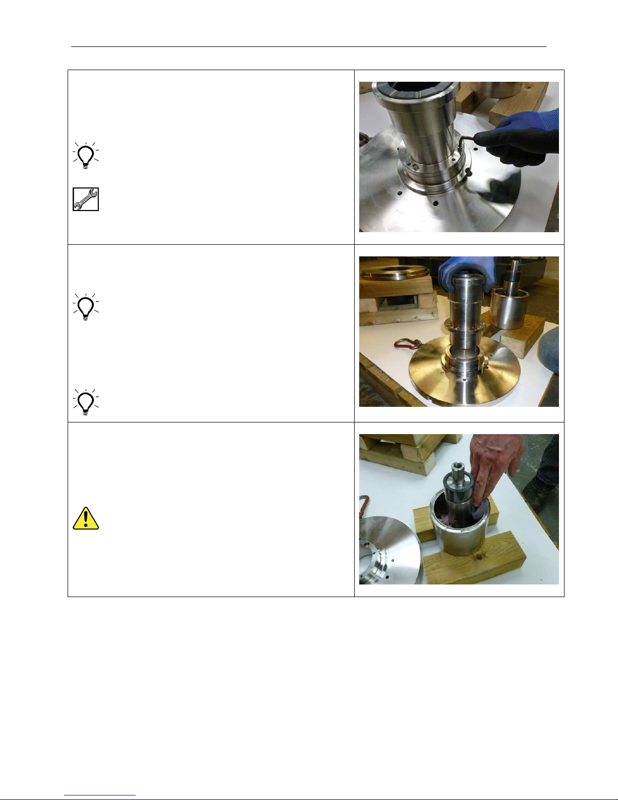
Disassembly – Stage 3 – Magnet Drive Unit
3.25 Remove 4 off Bush Holder Screws (14.S41).
Fit 2 off Screws to tapped holes for jacking if
required.
Only two of the tapped holes will have correct
thread for the screws.
3/16" Hex
3.26 Remove Bush Holder (09.09) from Casing Plate
(14.14).
Only store Bush Holder on its side, or if stored
vertically ensure Silicon Carbide bearing rests on
soft protective matting surface.
For changing Silicon Carbide Bushes and
Thrust Pad refer to appropriate section shown
on Contents page at the beginning of this
manual.
If Bushes and Thrust Pad are not worn or damaged
they can be left in place.
3.27 Wedge rags inside Inner Magnet Ring (37.37) and
up to Back Thrust Washer (37.12) to prevent
Thrust Washer from falling out during handling.
The Inner Magnet Ring contains strong magnets
and care should be taken near ferrous materials.
For example, if workbench top is metal ensure it
has a covering of hardboard, plywood, or plastic
sheeting. Also be careful when using tools around
this component.
SA-07-11-92, Rev Orig 58 October 2015
Page 66
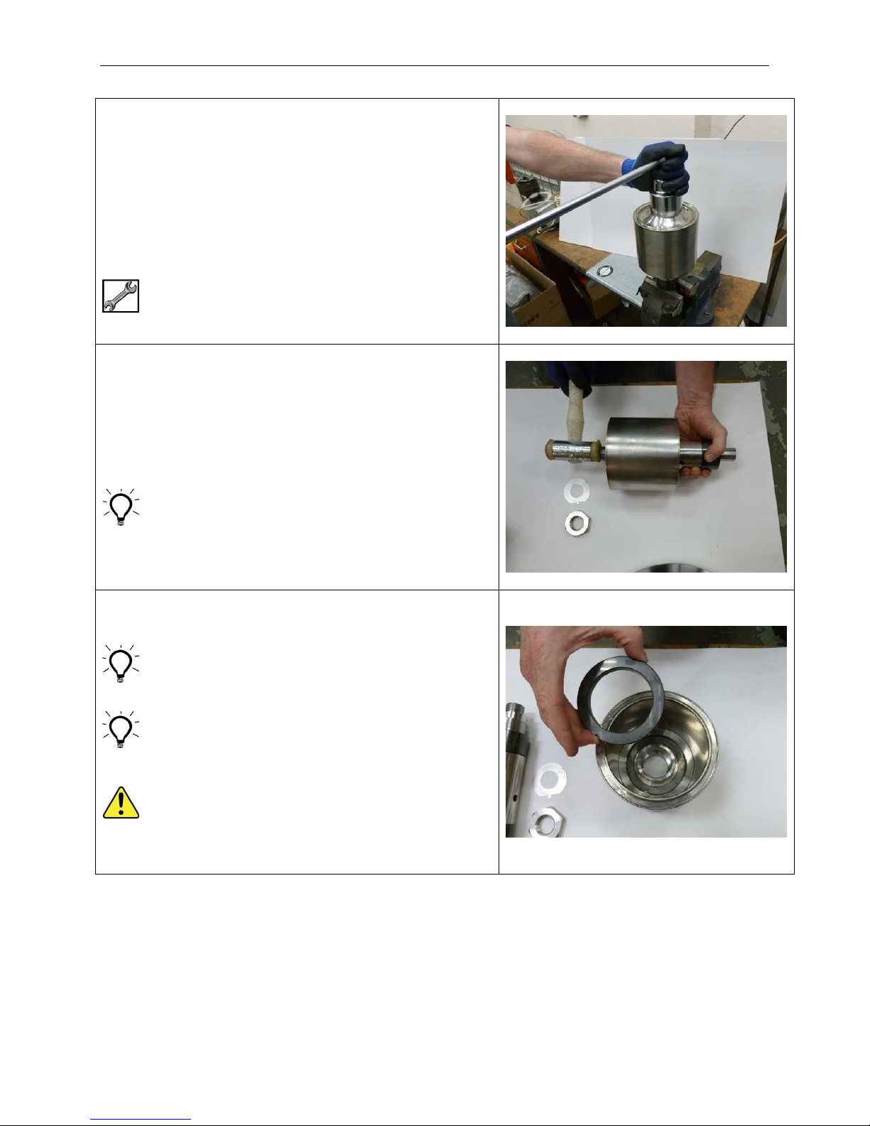
Disassembly – Stage 3 – Magnet Drive Unit
3.28
Turn over Inner Magnet Ring (37.37) and hold in a
vice with soft jaws fitted. Turn assembly clockwise
until key (02.K31) locks against jaw before fully
tightening vice.
Turn down tab on Coupling Washer (02.05) and
loosen but do not remove Coupling Nut (02.36).
LEFT HAND THREAD
Loosen in a CLOCKWISE direction
50mm AF
3.29 Stand Inner Magnet Ring (37.37) on its side on
protective surface and remove Coupling Nut (02.36)
and Tab Washer (02.05).
Drift out Shaft (02.02) with a soft mallet.
Support Pump Shaft as it comes free from its
location to protect Silicon Carbide Sleeves (02.86)
and Thrust Washer (37.12).
3.30 Remove Back Thrust Washer (37.12) from Inner
Magnet Ring (37.37).
Note that if Back Thrust Washer (37.12) is in good
condition it can be left in place in the Inner Magnet
Ring (37.37).
If difficult to remove, use compressed air or
decontamination bath to loosen solidified product.
In extreme cases it may have to be broken into
pieces with hammer and punch.
Wear correct protective clothing, including overalls,
gloves, safety glasses or face shield. Ensure
location groove is clean and free from burrs, dents
etc. before inserting new Front Thrust Washer
when re-building.
SA-07-11-92, Rev Orig 59 October 2015
Page 67
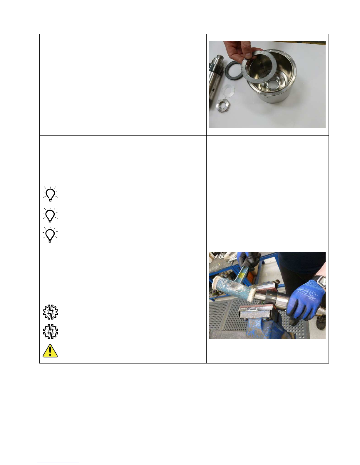
Disassembly – Stage 3 – Magnet Drive Unit
3.31 If the Back Thrust Washer (37.12) has been
removed then also remove and discard Alignment
Pad (37.39) from Inner Magnet Ring (37.37).
3.32 Hold main body of Pump Shaft (02.02) in a vice
with soft jaws.
Grip the Silicon Carbide Sleeve (08.86) with both
hands and pull Sleeve from Pump Shaft (02.02).
A sharp pulling action may be required to overcome
friction of the locating O-rings (02.OR1) in the bore
of the Sleeve.
Wear appropriate gloves and eye protection as
Silicon Carbide is brittle and can produce sharp
edges when broken.
If Shaft Sleeves (02.86) are not worn or damaged
they can be left in place.
3.33 ALTERNATIVE METHOD
Carefully grip Silicon Carbide Sleeve (02.86) in soft
jaws of a bench vice.
Use a soft mallet to drift Pump Shaft (02.02) from
Sleeve.
Support Shaft as it exits Sleeve.
Soft jaws with fibre faces must be used to avoid
cracking Silicon Carbide Sleeves.
Over-tightening the vice will break the Sleeve.
Eye protection must be worn in case Silicon
Carbide fractures or splinters.
Image not available
SA-07-11-92, Rev Orig 60 October 2015
Page 68
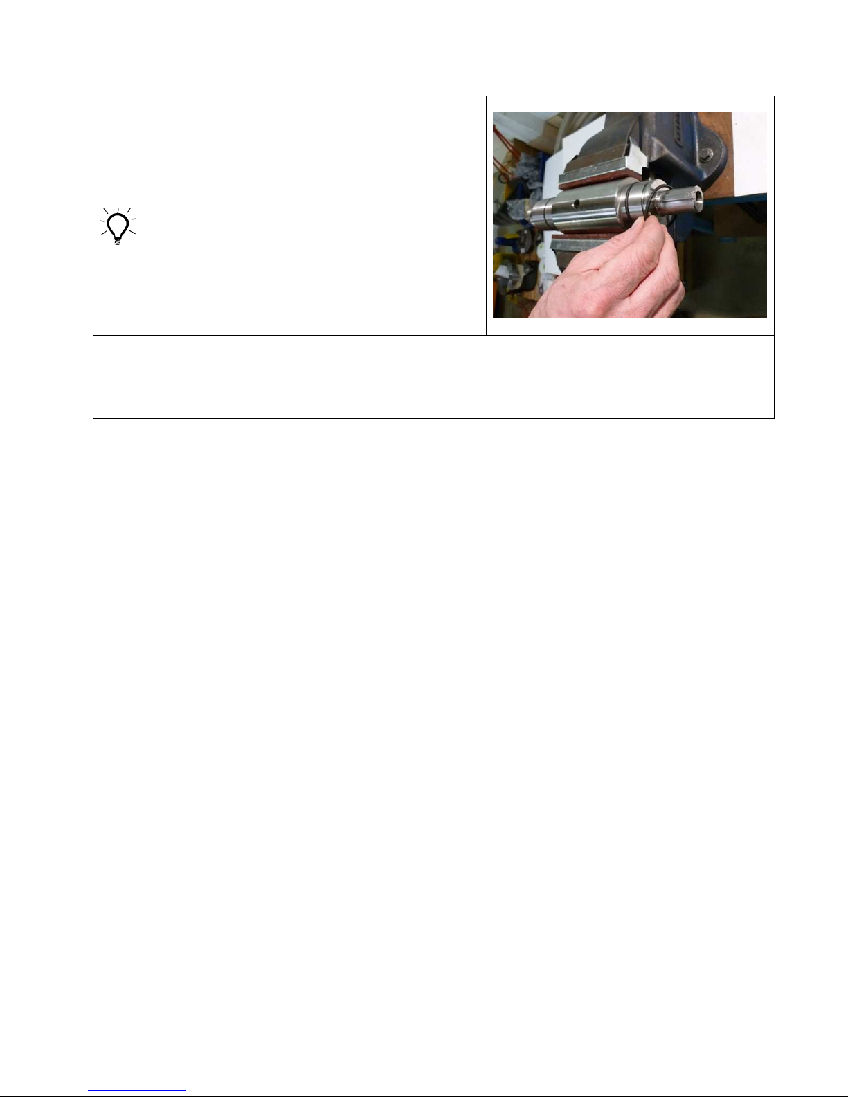
Disassembly – Stage 3 – Magnet Drive Unit
3.34 Remove O-Rings (02.OR1) from their grooves on
both ends of Shaft and discard.
Put all parts disassembled so far in clean, dry, safe
place until rest of Pump has been stripped.
Magnet Drive Unit is now completely disassembled
SA-07-11-92, Rev Orig 61 October 2015
Page 69
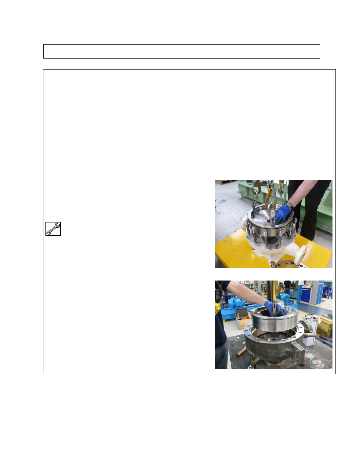
Disassembly - Stage 4 – Casing and Diffusers
Casing with Diffuser fitted, ready for disassembly
4.01 Fit 3 off Eye Bolts to tapped holes in top face of
Diffuser (33.33).
Attach suitable lifting gear and lift Diffuser from
pump Casing (41.41).
Image not available
3 x Eye Bolts 3/16”
4.02 ALTERNATIVE METHOD
If a large diameter impeller is fitted there may not
be enough wall thickness for eye bolt holes in
Diffuser (33.33).
If this is the case use a 3 leg puller (with reverse
legs) through the eye of the Diffuser to enable
extraction from the Casing (41.41).
SA-07-11-92, Rev Orig 62 October 2015
Page 70
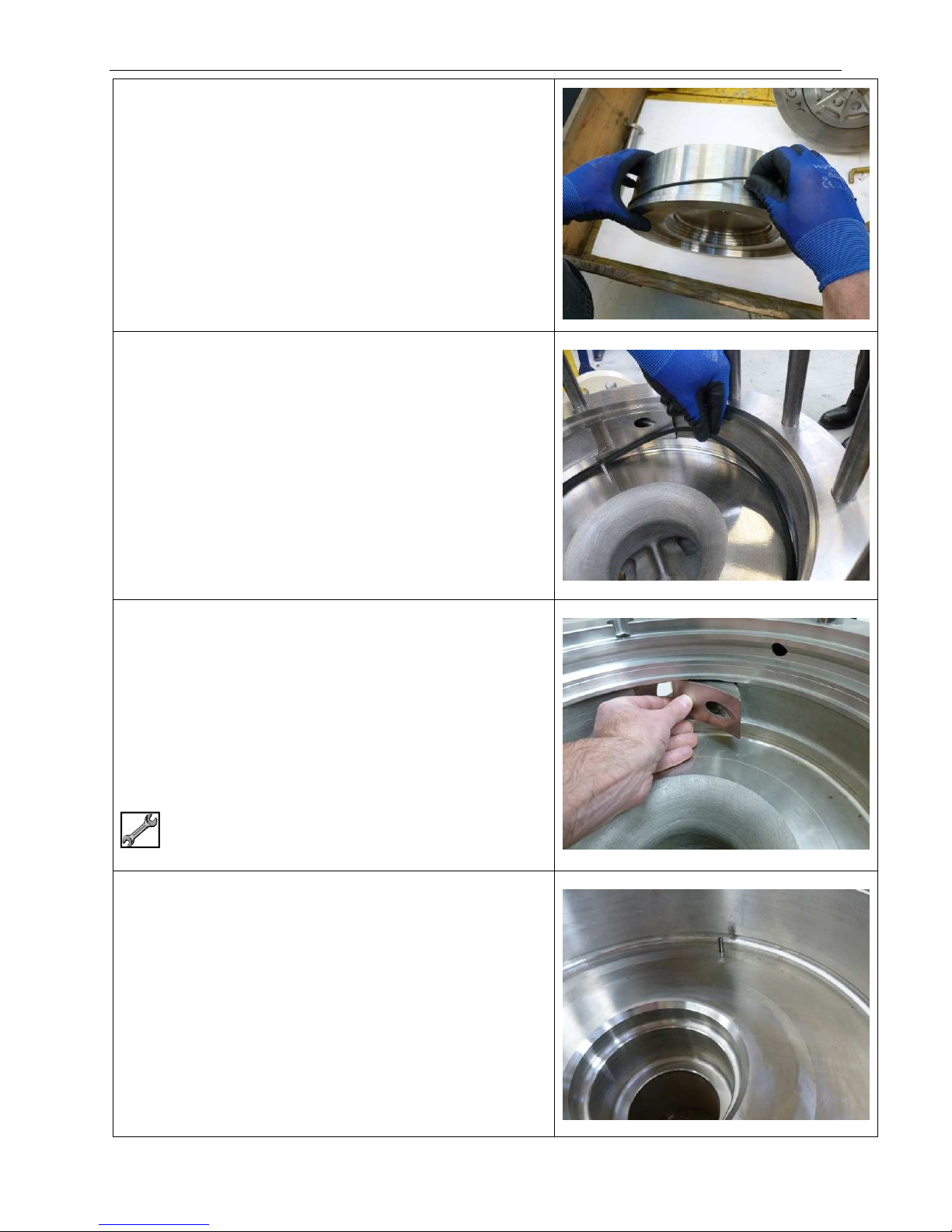
Disassembly – Stage 4 – Casing and Diffusers
4.03 Remove O-Ring (33.OR2) from Diffuser (33.33)
and discard.
4.04 Remove O-Ring (41.OR1) from bottom face of
Casing (41.41) and discard.
4.05 High head hydraulics are fitted with a Cone
Extension in the side wall of pump Casing (41.41)
positioned in line with the discharge nozzle.
Removal of Cone Extension is only required for
inspection or replacement purposes.
To remove Cone Extension, push in one end and
the other end will slide out. Remove completely
from cavity.
A Soft Mallet may be required to aid removal.
4.06 Two pins (41.49B) in the bottom face of Casing
(41.41) can be left in place unless they are
damaged in which case they will need to be pulled
out.
SA-07-11-92, Rev Orig 63 October 2015
Page 71
ASSEMBLY OF PUMP
To prevent leaks, ensure all Jacking Screws used to disassemble the Pump are either removed or
withdrawn to their original position during assembly.
Make sure all machined surfaces are clean and free from debris, bumps, bruises and scratches.
Note that small errors of alignment near the motor are magnified further away from the motor where
the Outer Magnet Ring (51.51) will be running with close clearances to other components.
Dress any surface damage with a stone.
When tightening fasteners, refer to the Torque Settings table located at the end of the manual for
the correct torque requriements.
Refer to Sectional Drawing and Parts List supplied with pump documents for component
identification. Numbers below in parenthesis refer to item numbers shown on the Parts List.
The pump can be split into three discrete assemblies for maintenance purposes:
Motor and Motor Support
Magnet Drive Unit
Casing and Diffuser
These will be considered at different stages in the instructions below.
The Inner Magnet Ring (37.37) and Outer Magnet Ring (51.51) contain strong magnets and care
should be taken in the vicinity of ferrous materials.
For example, if workbench top is metal, ensure it has a covering of hardboard, plywood, or plastic
sheeting. Also be careful when using tools around these components.
Note that two cranes or lifting devices will be required to maneuver the pump parts into position for
maintenance.
SA-07-11-92, Rev Orig 64 October 2015
Page 72
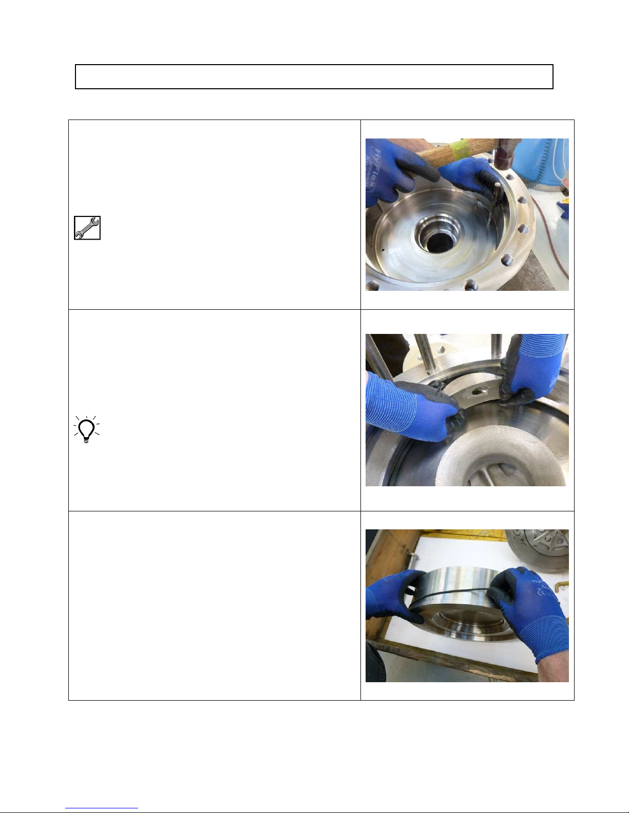
Assembly - Stage 1 – Casing and Diffuser
1.01 Fit new pins (41.49B) to bottom face of Casing
(41.41) if required.
Hammer
Punch
1.02 Ensure machined cone in Cone Extension is clean
and free of debris.
Replace Cone Extension into cavity in wall of
Casing (41.41) and ensure it is flush with Casing
bore.
Ensure Cone Extension is correct way round so
that discharge hole in Cone Extension lines up with
discharge hole in Diffuser when Diffuser is fitted.
1.03 Fit new O-Ring (33.OR2) up to shoulder on Diffuser
(33.33).
SA-07-11-92, Rev Orig 65 October 2015
Page 73
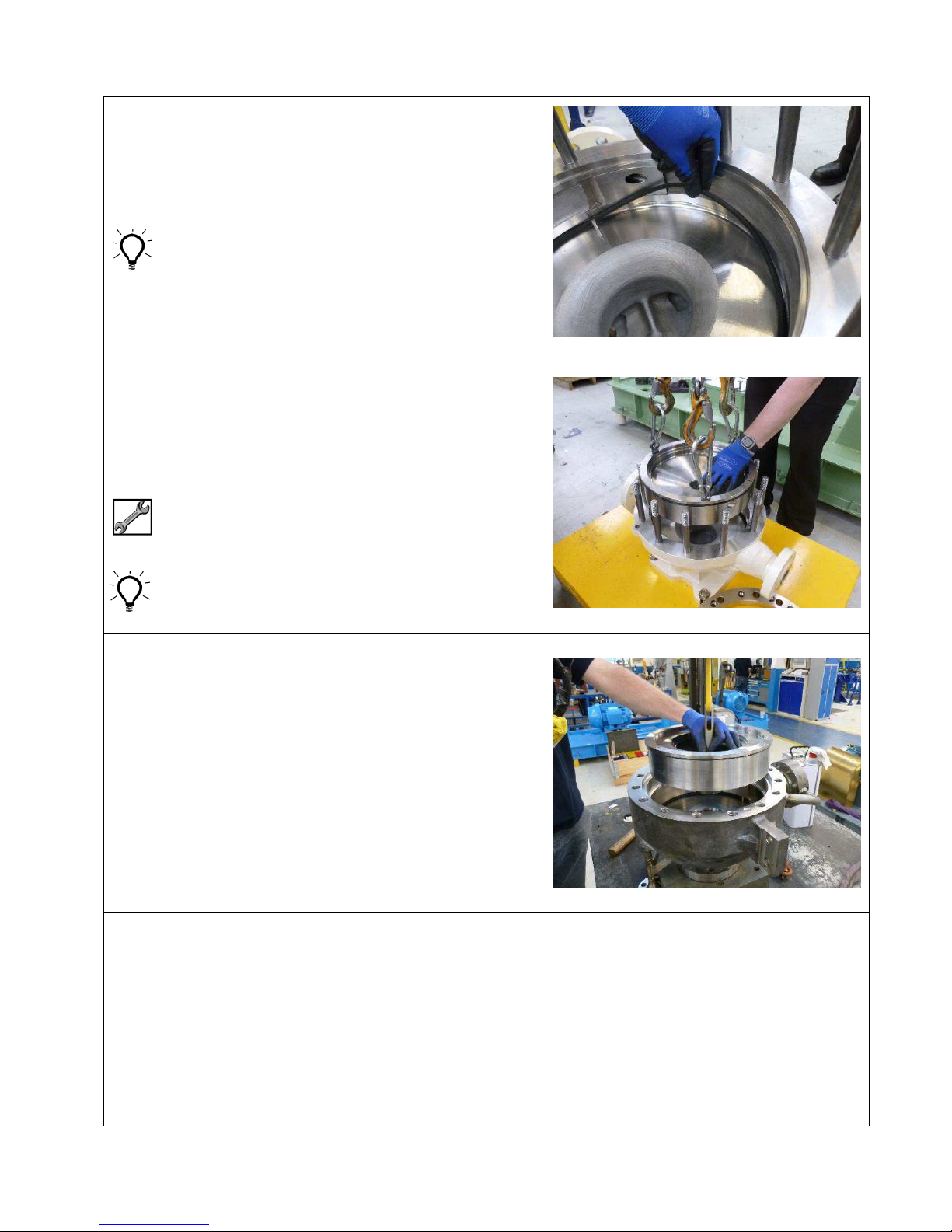
1.04 Fit new O-Ring (14.OR1) in bottom corner of bore
of Casing (41.41).
Stretch O-Ring by hand before fitting to ensure it is
pushed up to Casing inside diameter.
This will prevent it getting pinched when the
Diffuser (33.33) is fitted.
1.05 Fit 3 off Eye Bolts to tapped holes in top face of
Diffuser (33.33) and fit suitable lifting gear.
Attach suitable lifting gear to Eye Bolts.
Line up with holes in face of Diffuser (33.33) with
pins in Casing (41.41) and lower Diffuser carefully
into Casing.
5/16” UNC Eye Bolts (3 off)
Pins are not equi-spaced to ensure discharge of
Diffuser (33.33) will be aligned with discharge of
Casing (41.41).
1.06 ALTERNATIVE METHOD
If a large diameter impeller is fitted there may not
be enough wall thickness for eye bolt holes in
Diffuser (33.33).
If this is the case use a 3 leg puller (with reverse
legs) through the eye of the Diffuser to enable the
Diffuser to be lowered into Casing (41.41).
Casing and Diffuser are now complete
SA-07-11-92, Rev Orig 66 October 2015
Page 74
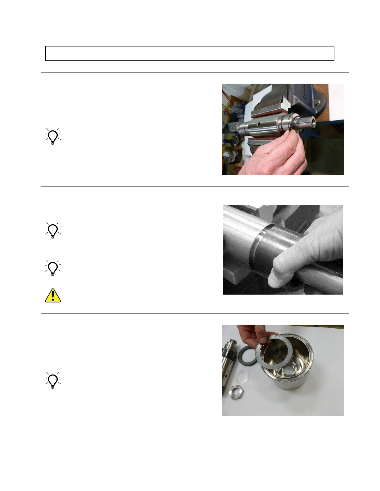
Assembly - Stage 2 – Magnet Drive Unit
2.01 Hold main body of shaft in vice fitted with soft jaws.
Fit O-Rings (02.OR1) into their grooves on both
ends of Pump Shaft (02.02).
Ensure Pump Shaft centre hole and cross-holes are
clear of sludge or solidified product.
2.02 Fit new Shaft Sleeves (02.86).
Note that a firm rotating and pushing action will be
needed to fit Sleeve over O-Rings.
If Kalrez® or similar type O-Rings are less pliable
than standard Viton® type O-Rings, Sleeves may
therefore need to be fitted with care using a hand
operated or small pneumatic press.
Use a suitable lubricant compatible with the
pumped liquid in the bore of the Sleeve to aid
assembly (if permitted).
Wear appropriate gloves and eye protection as
silicon carbide is brittle and can produce sharp
edges when broken.
2.03 Fit new Alignment Pad (37.39) to Inner Magnet
Ring (37.37) and ensure Alignment Pad locates
correctly over Thrust Washer Drive Pin (37.49).
Ensure location groove is clean and free from burrs,
dents etc. before inserting new Alignment Pad and
SA-07-11-92, Rev Orig 67 October 2015
Page 75
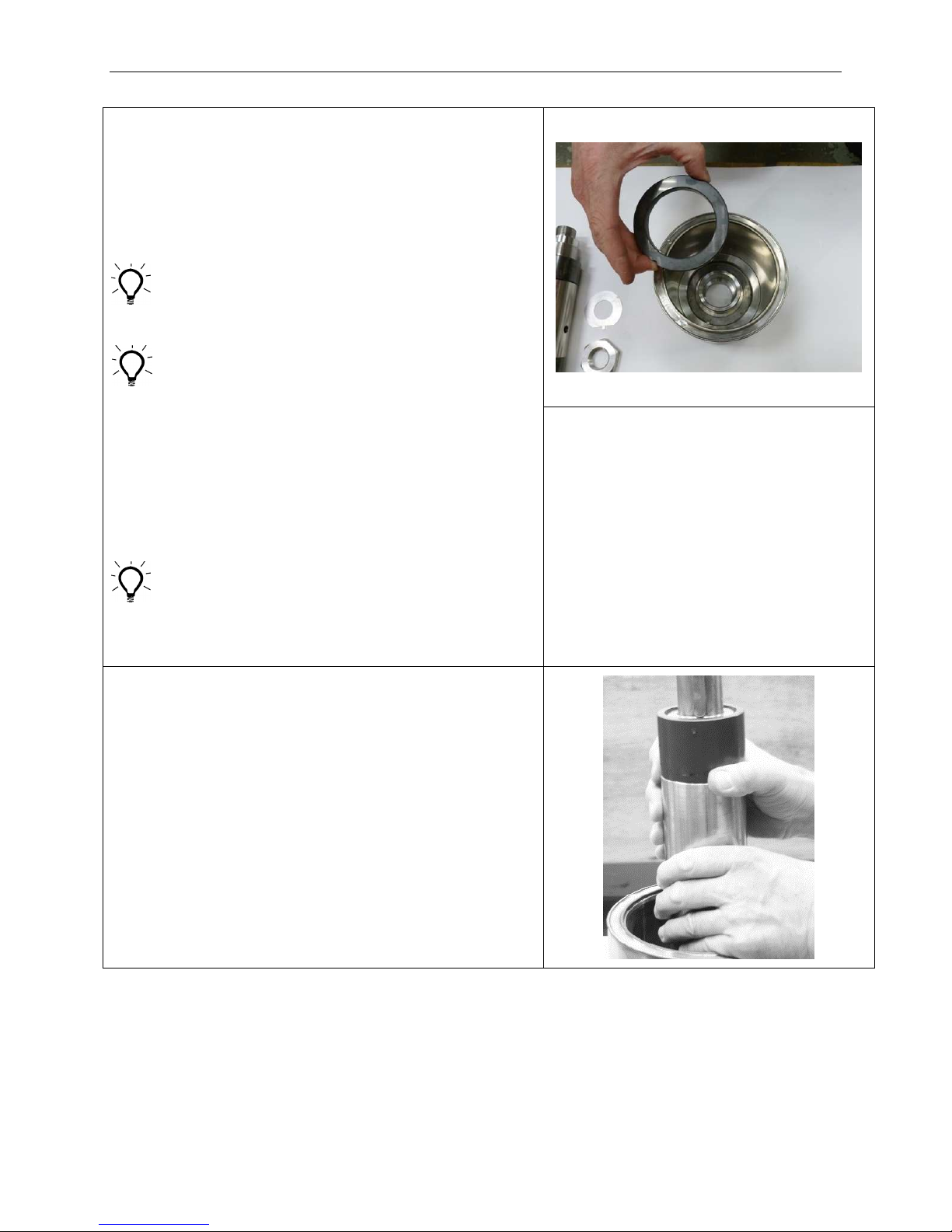
Assembly – Stage 2 – Magnet Drive Unit
2.04 Fit new Back Thrust Washer (37.12).
Note that one side may have grooves.
ENSURE PLAIN SIDE IS FACE UP.
Ensure Back Thrust Washer locates correctly over
Thrust Washer Drive Pin (37.49).
Some Thrust Washers are plain on one side and
grooved on the other. Make sure the grooved side
is facing down and sitting on the Alignment Pad
(37.39).
Use fingers to rotate Thrust Washer from side-to-
side about Pin to ensure Thrust Washer is seated
correctly and free to move.
2.05 Fit Impeller Location Key (02.K31) to Pump Shaft
(02.02) if required.
Check that impeller (06.06) fits correctly over pump
shaft and key.
2.06 Fit Pump Shaft (02.02) to Inner Magnet Ring
(37.37).
Image not available
SA-07-11-92, Rev Orig 68 October 2015
Page 76
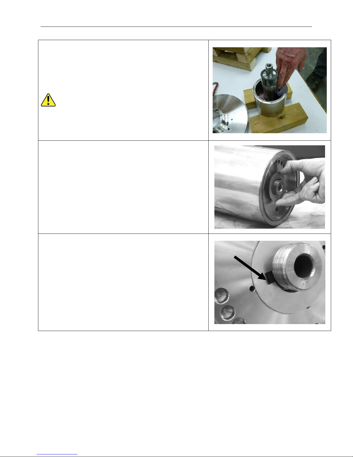
Assembly – Stage 2 – Magnet Drive Unit
2.07 After fitting Pump Shaft (02.02), pack clean lint-free rag
around Pump Shaft and down onto Back Thrust
Washer (37.12).
This will prevent Back Thrust Washer falling from its
location during handling of the Inner Magnet Ring
(37.37).
The Inner Magnet Ring contains strong magnets and
care should be taken near ferrous materials.
For example, if workbench top is metal ensure it has a
covering of hard board, plywood or plastic sheeting.
Also be careful when using tools around this
component.
2.08 Fit new Coupling Washer (02.05) to Pump Shaft
(02.02).
2.09 Ensure anti-rotation tab (arrowed) is turned down into
location hole.
SA-07-11-92, Rev Orig 69 October 2015
Page 77
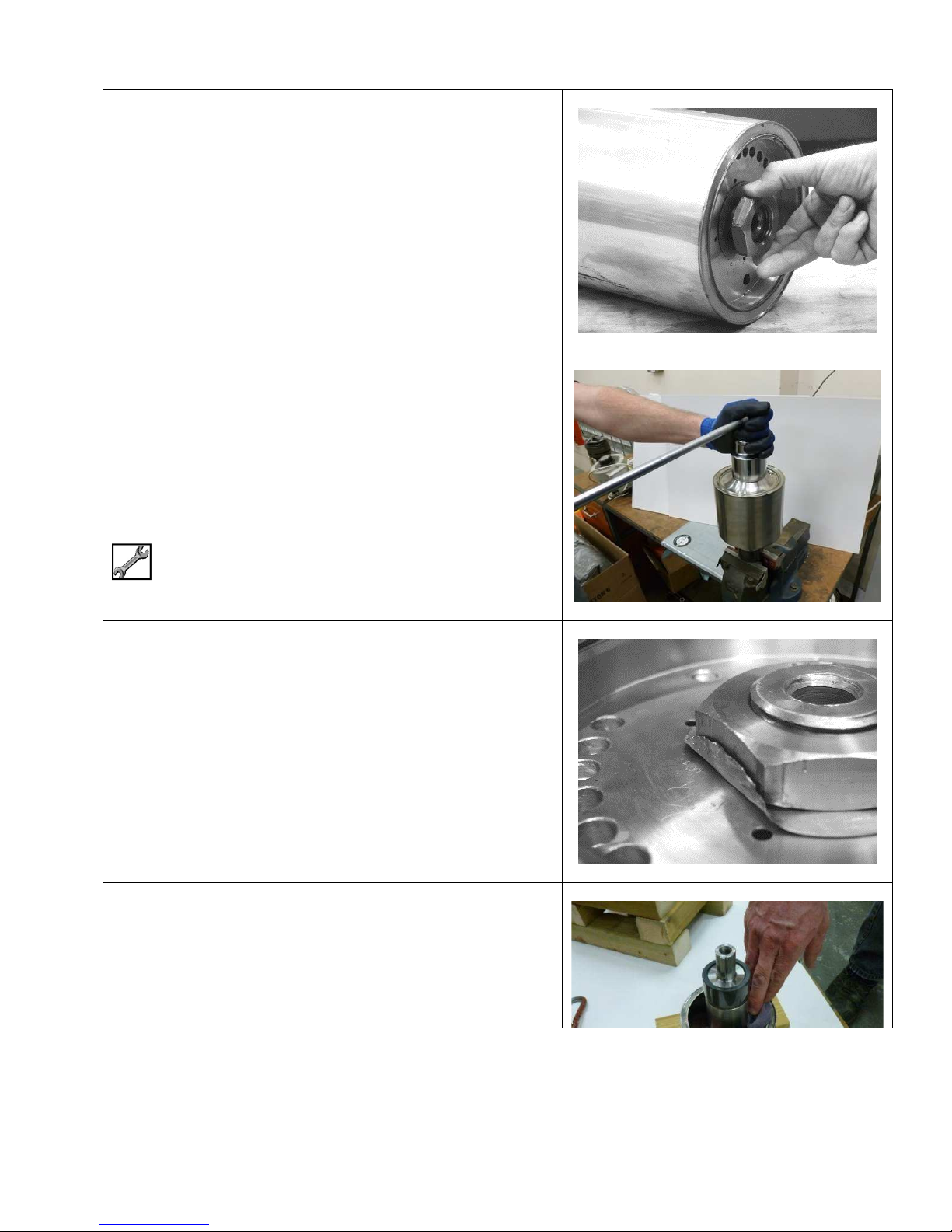
Assembly – Stage 2 – Magnet Drive Unit
2.10 Fit Coupling Nut (02.36) to Pump Shaft (02.02).
Tighten finger tight.
EFT HAND THREAD
Tighten in an ANTI-CLOCKWISE direction
2.11 Turn over Inner Magnet Ring (37.37) and hold in a
vice with soft jaws fitted. Turn assembly anti-clockwise
until key (02.K31) locks against jaw before fully
tightening vice.
Tighten Coupling Nut (02.36).
LEFT HAND THREAD
Tighten in an ANTI-CLOCKWISE direction
50mm AF
100 Nm (74 lbf-ft)
2.12 Use pry bar to turn up section of Coupling Washer
(02.05) onto Coupling Nut (02.36).
2.13 Remove Pump Shaft with IMR attached from vice and
place on low level work surface.
Remove rag that was previously pushed between
Pump Shaft (02.02) and Inner Magnet Ring (37.37).
SA-07-11-92, Rev Orig 70 October 2015
Page 78
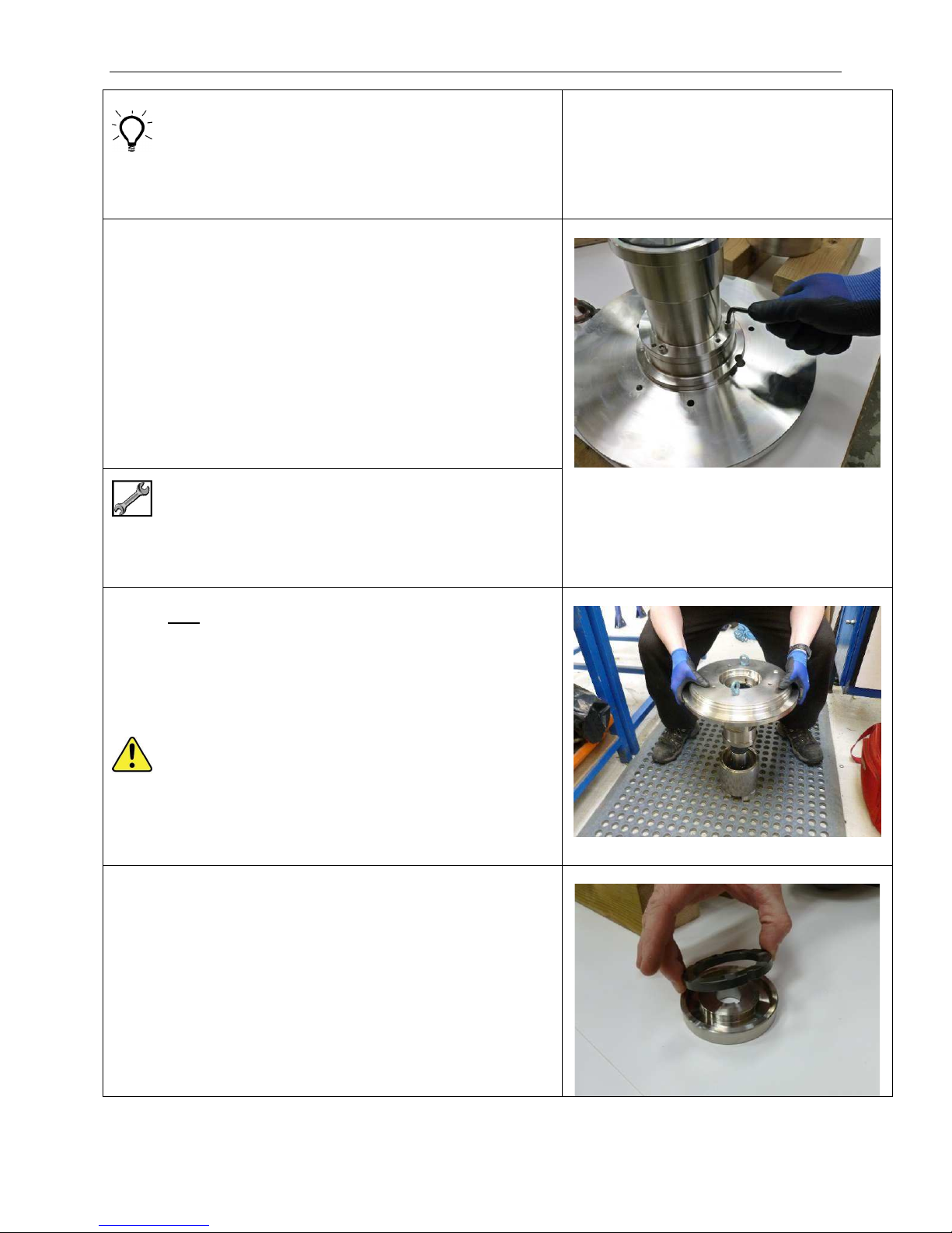
Assembly – Stage 2 – Magnet Drive Unit
For ZeroLoss Containment Shell (20.20) the Inner
Magnet Ring (37.37) must be supported either side of
the protruding nut.
2.14 Fit Bush Holder (09.09) to Casing Plate (14.14) and
align off-set retention holes.
Fit Bush Holder retention Screws (14.S41) and tighten
evenly by hand.
3/16" Hex
Fully tighten by hand.
2.15 Very carefully lower Casing Plate (14.14) complete
with Bush Holder (09.09) over Pump Shaft (02.02).
Extreme care must be taken not to damage Silicon
Carbide bearings as Bush Holder slides over Pump
Shaft.
Casing Plate with attached Bush Holder can weigh
more that 25 kg (55 lbs).
2.16 Fit new Thrust Washer (07.07A) if required to Thrust
Washer Holder (07.07).
Ensure it locates correctly over Thrust Washer
Location Pin (07.49).
SA-07-11-92, Rev Orig 71 October 2015
Page 79
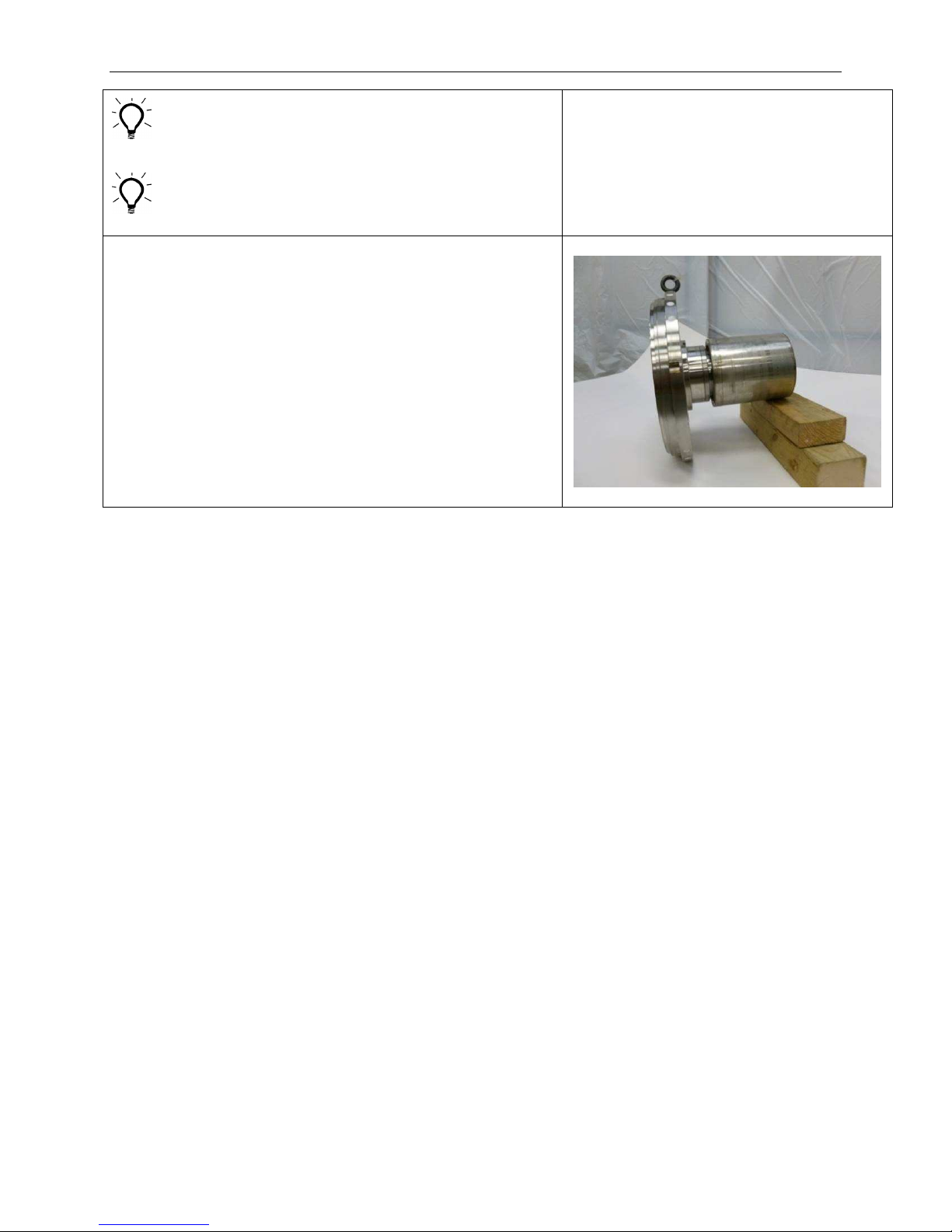
Assembly – Stage 2 – Magnet Drive Unit
Ensure location groove is clean and free from burrs,
dents etc. before inserting new Front Thrust Washer
when re-building.
Rotate Thrust Washer from side-to-side about Pin to
ensure Thrust Washer is seated correctly.
2.17 Tip assembly over and lower Casing Plate (14.14)
onto bench.
Lift Inner Magnet Ring (37.37) so that Pump Shaft
(02.02) runs uphill towards the Inner Magnet Ring.
Support Inner Magnet Ring.
SA-07-11-92, Rev Orig 72 October 2015
Page 80
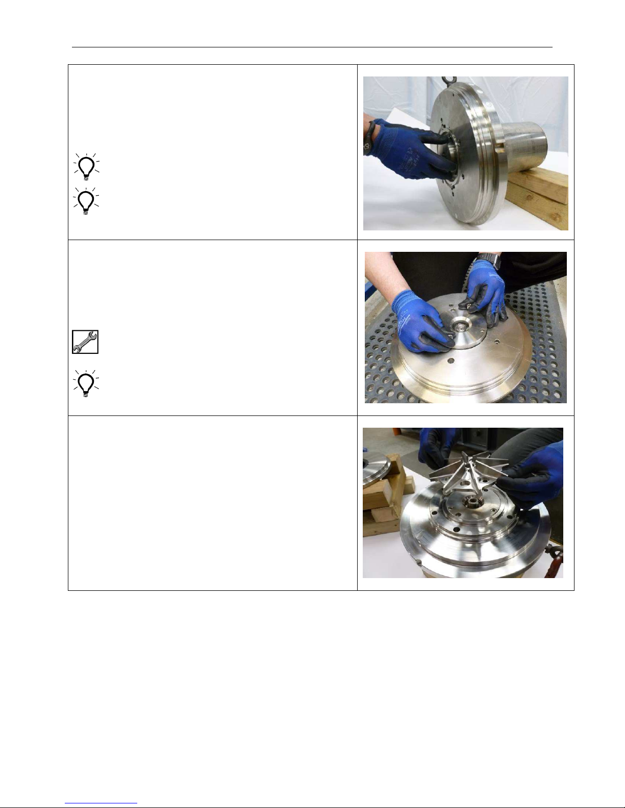
Assembly – Stage 2 – Magnet Drive Unit
2.18 Slide Thrust Washer Holder assembly (07.07) over
Pump Shaft (02.02) and up to Shaft Sleeve (02.86).
Stand assembly vertically again.
Ensure Thrust Washer (07.07A) remains seated
correctly in Thrust Washer Holder during fitting.
Fit Casing Plate Cover retention Screws (14.S45) to
tapped holes provided in back of Thrust Washer
Holder to aid assembly.
2.19 Lower Casing Plate Cover (14.40) into Casing Plate
(14.14) location.
Fit retention Screws (14.S45) and tighten with
torque wrench.
7/32" or 1/4" Hex
25 Nm (18 lbf-ft)
Fit screws to tapped holes in Casing Plate Cover to
aid assembly.
2.20 Fit Impeller (06.06) to Pump Shaft (02.02).
SA-07-11-92, Rev Orig 73 October 2015
Page 81
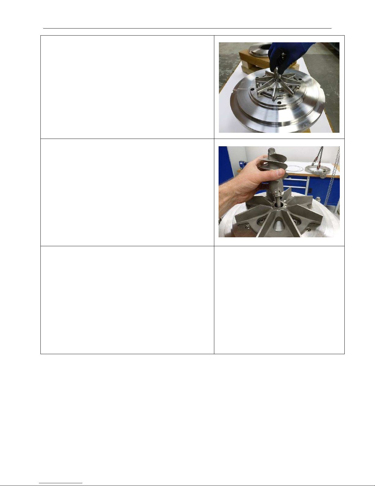
2.21 NO INDUCER OPTION
Fit Impeller Tab Washer (02.05A) and Impeller
Fastener (02.03).
LEFT HAND THREAD
Do not fully tighten at this stage.
2.22 INDUCER OPTION
Occasionally an Inducer (76.01) will be fitted in
place of the Impeller Fastener.
Fit Stud (02.48A) into Inducer (76.01) and tighten
until Stud bottoms in hole.
Fit Inducer together with Stud and Tab Washer
(02.05A) to retain Impeller (06.06) to Pump Shaft
(02.02).
Assembly – Stage 2 – Magnet Drive Unit
LEFT HAND THREAD
Do not fully tighten at this stage.
2.23 Stand Coupling Housing (43.43) vertically on bench
with large flange uppermost.
Image not available
SA-07-11-92, Rev Orig 74 October 2015
Page 82

Assembly – Stage 2 – Magnet Drive Unit
2.24 METAL CONTAINMENT SHELL OPTION
Lower Containment Shell (20.20) into Coupling
Housing (43.43).
Align retention screw holes in Coupling Housing
with tapped holes in rear of Containment Shell
flange.
2.25 METAL CONTAINMENT SHELL OPTION
Fit Retention Screws (20.S42) through Coupling
Housing (43.43) and tighten evenly from side to
side.
5/16” Hex
Image not available
Image not available
35 Nm (26 lbf-ft)
2.26 ZEROLOSS CONTAINMENT SHELL OPTION
Fit Containment Shell Flange into recess in flange
of Coupling Housing (43.43).
Align retention screw holes in Coupling Housing
with tapped holes in rear of Containment Shell
flange.
2.27 ZEROLOSS CONTAINMENT SHELL OPTION
Fit Retention Screws (20.S42) through Coupling
Housing (43.43) and tighten evenly from side to
side.
Image not available
Image not available
SA-07-11-92, Rev Orig 75 October 2015
Page 83
Assembly – Stage 2 – Magnet Drive Unit
5/16” Hex
35 Nm (26 lbf-ft)
2.28 ZEROLOSS CONTAINMENT SHELL OPTION
Fit O-ring (20.OR1) to groove in metallic flange.
O-ring will need to be slightly stretched in order to fit
into groove, this can easily be done by hand.
Care should be taken when stretching PTFE.
Ensure O-ring and groove are clean.
2.29 ZEROLOSS CONTAINMENT SHELL OPTION
Image not available
Lower Containment Shell (20.20) into metallic
flange so that shell lip drops into location bore.
Align cut-outs in shell face with tapped holes on
metallic flange.
Ensure O-ring remains seated in groove when
fitting Containment Shell.
2.30 Fit 2 off Eye Bolts to tapped holes in outside
diameter of Casing Plate (14.14).
Attach suitable lifting gear and lift Casing Plate
complete with rotating assembly.
5/16” Eye Bolts x 2
Image not available
Image not available
SA-07-11-92, Rev Orig 76 October 2015
Page 84
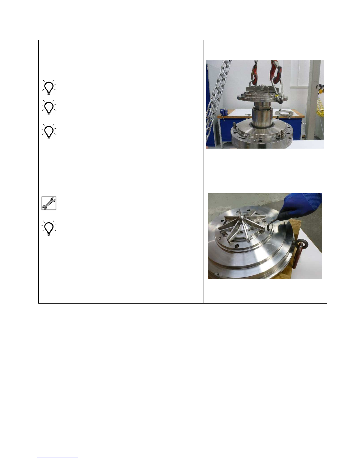
Assembly – Stage 2 – Magnet Drive Unit
2.31 Carefully lower Casing Plate and rotating assembly
into bore of Containment Shell (20.20).
Align retention screw holes with tapped holes in
flange of Containment Shell.
For ZeroLoss Containment Shell ensure O-Ring
has already been fitted between flange and shell.
Avoid bumping ZeroLoss Containment Shell as O-
ring may be dislodged from its groove.
To identify the correct position for hole alignment,
the internal feed hole in the face of Casing Plate
(14.14) is 45° to the left of the lifting eye hole in the
flange outside diameter of Coupling Housing
(43.43)
(feed hole may be hidden behind impeller).
2.32 Fit 3 off Casing Plate retention Screws (20.S41).
7/32" or 1/4" Hex
25 Nm (18 lbf-ft)
NOTE
In some cases the Impeller may cover or partially
cover the screw holes. If this is the case the
Impeller will need to be removed in order to fit the
screws and then replaced.
After refitting the Impeller check that it rotates
freely before fully tightening Impeller Fastener.
If the Impeller does not rotate freely it is possible
the rear Thrust Washer may have become
unseated when the shaft dropped as the impeller
fastener was loosened.
SA-07-11-92, Rev Orig 77 October 2015
Page 85
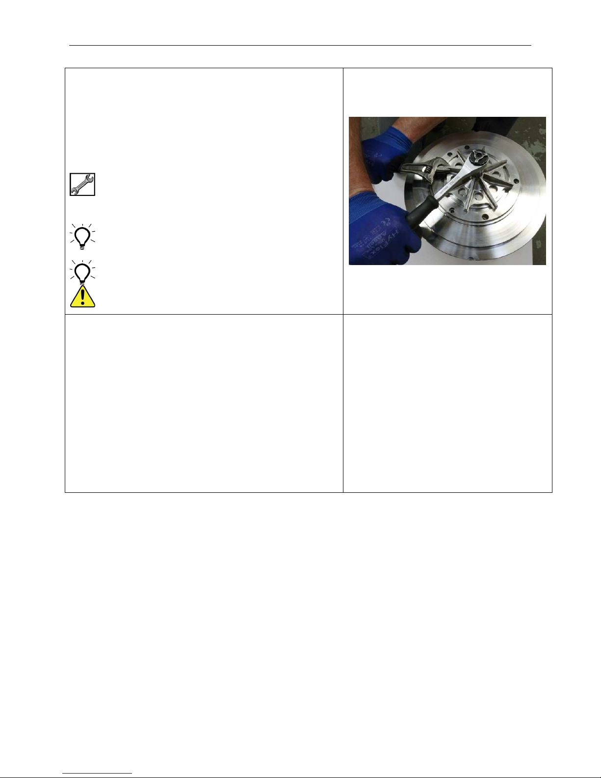
Assembly – Stage 2 – Magnet Drive Unit
2.33 Tighten Impeller Fastener (02.03) or Inducer
(76.01), whichever is fitted
LEFT HAND THREAD
Tighten in an ANTI-CLOCKWISE direction
Bend Tab Washer (02.05A) to ensure Impeller
Fastener or Inducer does not come loose.
3/4" AF (Narrow Line Impeller)
1-1/8" AF (Wide Line Impeller)
50 Nm (37 lbf-ft)
One of the impeller blades may be held with an
adjustable spanner whilst tightening fastener.
The Inducer, if fitted, has a small pocket either side
of the hub for tabs to bend into.
CAUTION – Assembly is stable but top heavy
2.34 Measure end float of rotating assembly (axial
clearance between thrust faces).
Set magnetic base on front flange face of Coupling
Housing (43.43).
Place Dial Test Indicator on front face of Impeller
(06.06).
Set Dial Test Indicator to zero.
Lift Impeller with suitable levers placed each side.
Allowable end float is 0.45 mm to 1.4 mm
(0.018" to 0.055").
No image available
SA-07-11-92, Rev Orig 78 October 2015
Page 86
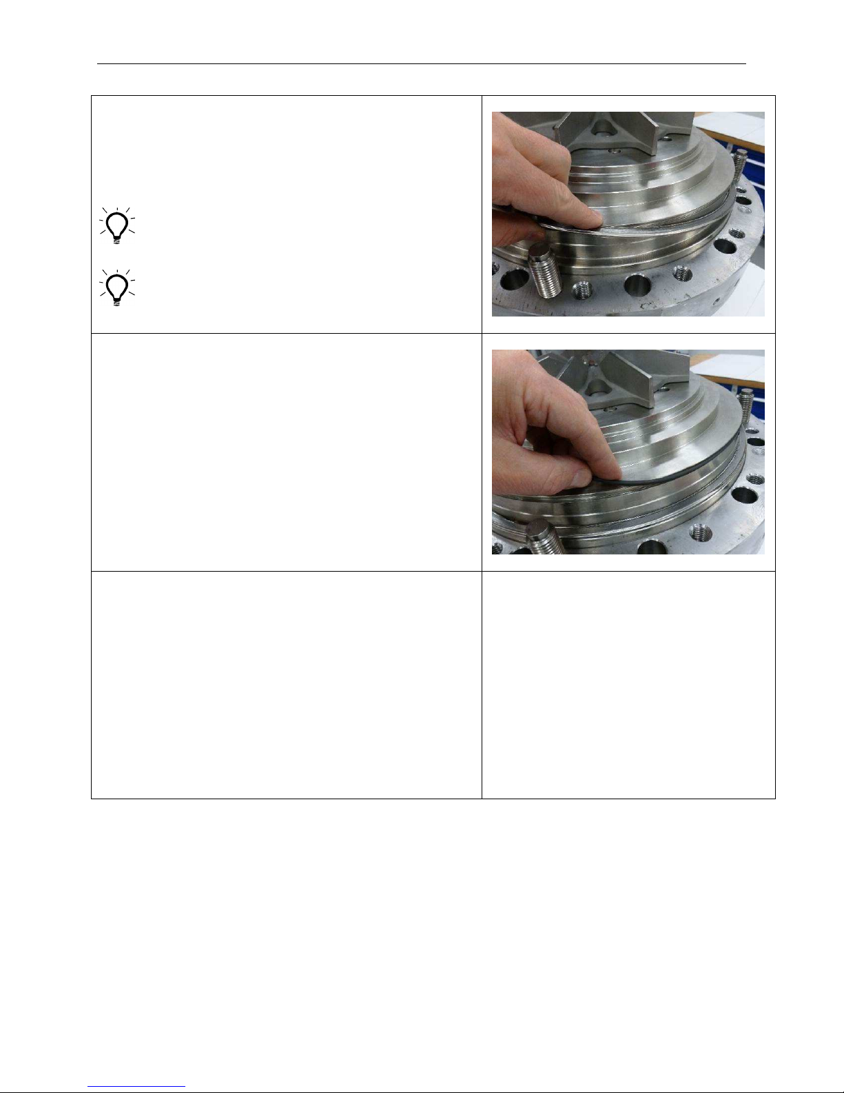
Assembly – Stage 2 – Magnet Drive Unit
2.35 Fit new Gasket (20.17) up to shoulder on flange of
Containment Shell (20.20).
Ensure Gasket seating face is free from dents and
scratches etc.
Ensure Gasket lies within the diameter of seating
face or it may be damaged when Adaptor Ring
(16.16) is fitted.
2.36 Fit new O-ring (14.OR3) into groove in outside
diameter of Casing Plate (14.14).
2.37 Fit new O-ring (14.OR2) up to FIRST shoulder on
front of Casing Plate (14.14).
Check O-ring is fitted on SMALLEST diameter of
Casing Plate.
SA-07-11-92, Rev Orig 79 October 2015
Page 87
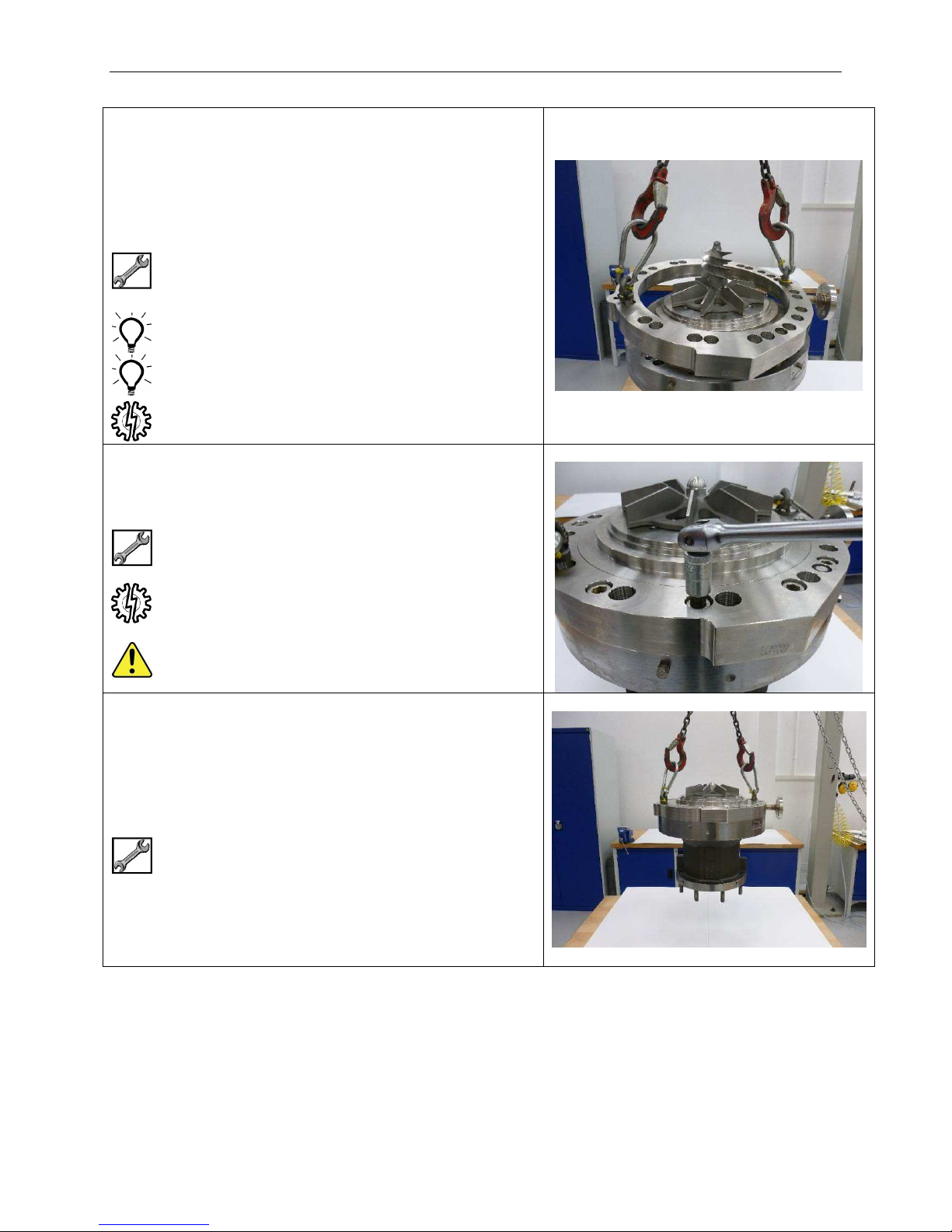
Assembly – Stage 2 – Magnet Drive Unit
2.38 Replace Jacking Screws (16.S51) with Eye Bolts.
Attach suitable lifting gear and lower Adaptor Ring
(16.16) over Casing Plate (14.14) and up to front
face of Coupling Housing (43.43).
5/16” Eye Bolts x 2
Soft Mallet
Position so that vent hole in outer diameter of
Casing Plate lines up with vent flange on Adaptor
Ring.
Adaptor Ring will need to be tapped on with a soft
Mallet due to friction of O-ring (14.OR3).
Be careful not to pinch Gasket (20.17).
2.39 Fit 12 off Retention Screws (43.S55) and tighten
evenly from side to side.
1/2” Hex
125 Nm (92 lbf-ft)
Gasket (20.17) is fully seated when there is no
longer a gap between Adaptor Ring (16.16) and
Coupling Housing (43.43).
CAUTION – Assembly is stable but top heavy.
2.40 Attach suitable lifting gear to eye Bolts already
fitted to Adaptor Ring (16.16).
Lift Magnet Drive Unit into the vertical position.
5/16” Eye Bolts x 2
SA-07-11-92, Rev Orig 80 October 2015
Page 88
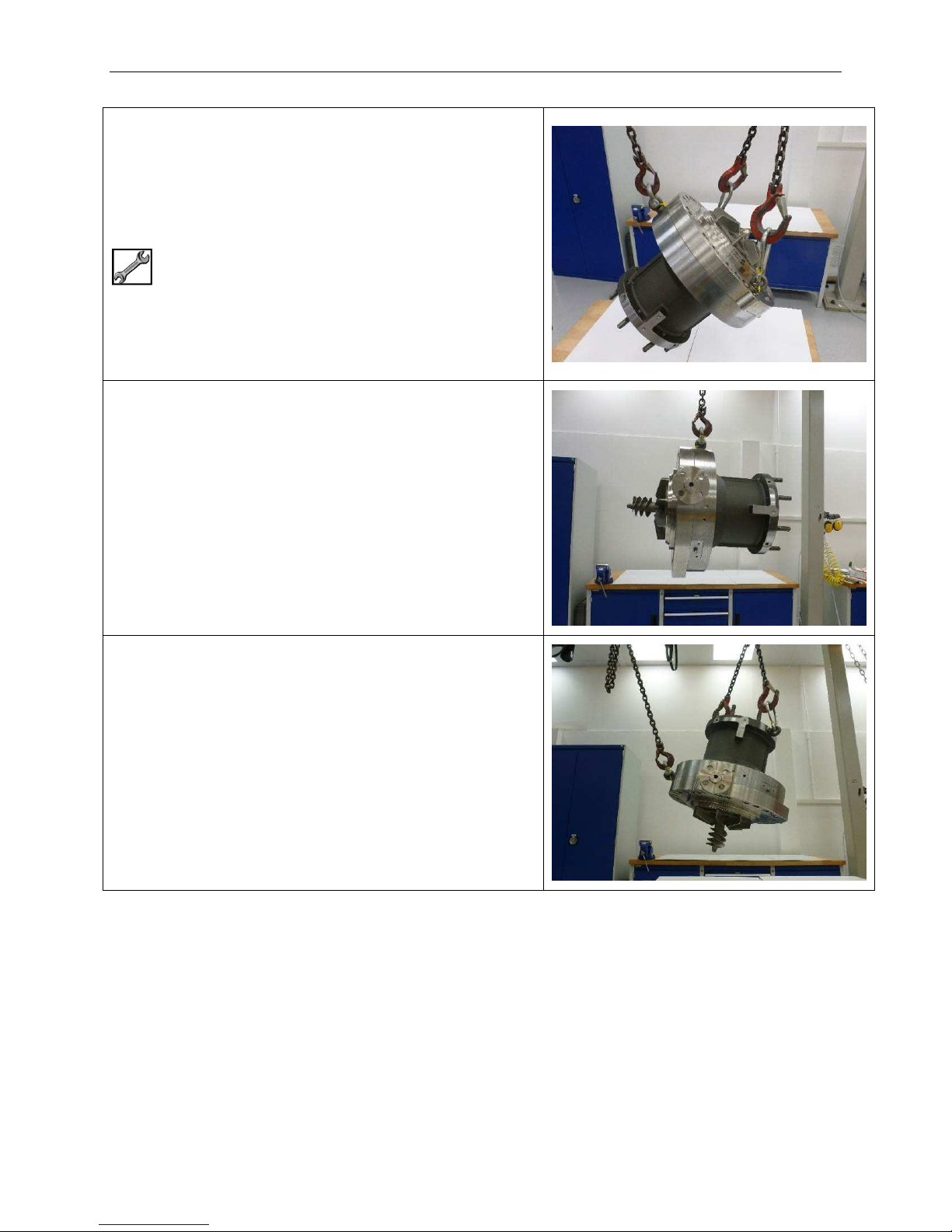
Assembly – Stage 2 – Magnet Drive Unit
2.41 Fit 1 off Eye Bolt to tapped hole in flange of
Coupling Housing (43.43).
Use a second lifting device to raise the Magnet
Drive Unit into a horizontal position.
½” Eye Bolt
2.42 Remove Eye Bolts from Casing Plate (14.14) and
replace with jacking Screws (16.S51).
(Image shows optional Inducer fitted to Impeller)
2.43 Fit Eye Bolts to tapped holes in outside of small
flange of Coupling Housing (43.43).
Use a second lifting device to lift pump into the
vertical position with impeller at the bottom.
(Image shows optional Inducer fitted to Impeller)
SA-07-11-92, Rev Orig 81 October 2015
Page 89
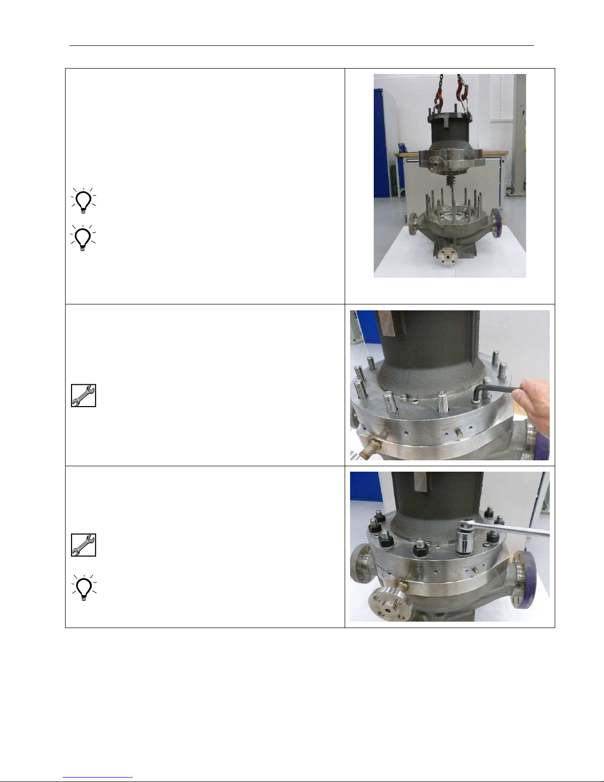
Assembly – Stage 2 – Magnet Drive Unit
2.44 Lower Magnet Drive Unit onto pump Casing
(41.41).
Take care to keep Drive Unit vertical when fitting,
especially if an Inducer (76.01) is fitted.
Align Eye Bolt hole in Coupling Housing flange with
discharge nozzle of Casing
Guide pins may be fitted to aid alignment.
Ensure O-ring (14.OR2) does not fall from Casing
Plate (14.14) during fitting.
Alternatively the O-ring may be positioned in the
corresponding location diameter of the Diffuser
(33.33).
If O-ring is fitted to Diffuser it will need slight
stretching to avoid getting pinched as Casing Plate
enters Diffuser.
2.45 Ensure 3 off Jacking Screws in flange of Coupling
Housing (43.43) have been backed off to allow
metal-to-metal contact between Coupling Housing
and Casing (41.41)
3/8” Hex
2.46 Fit 12 off Washers (41.W11) and Retention Nuts
(41.N11) to Studs (41.48).
Tighten Nuts evenly from side to side
1-1/4" AF
300 Nm (220 lbf-ft)
It may be helpful to number the nuts in order of
tightening sequence.
SA-07-11-92, Rev Orig 82 October 2015
Page 90
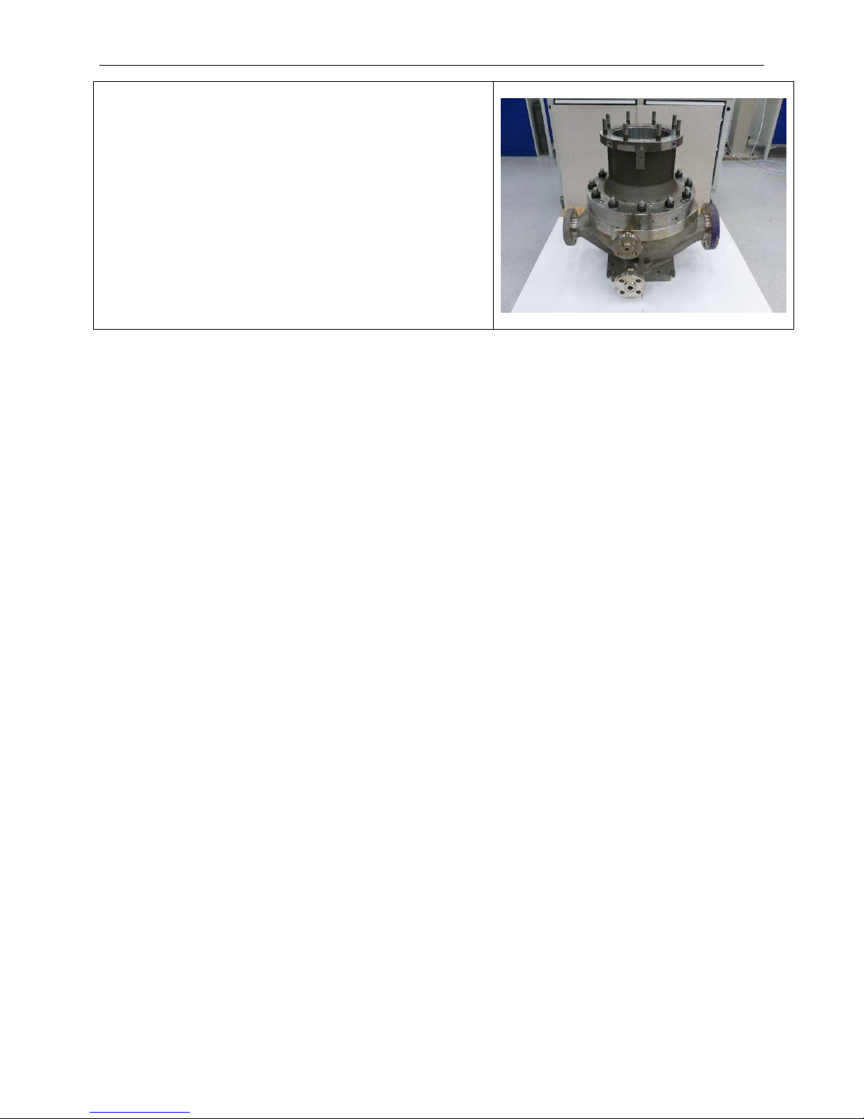
Assembly – Stage 2 – Magnet Drive Unit
STAGE 1 & 2 COMPLETE
MAGNET DRIVE UNIT FITTED TO CASING
SA-07-11-92, Rev Orig 83 October 2015
Page 91
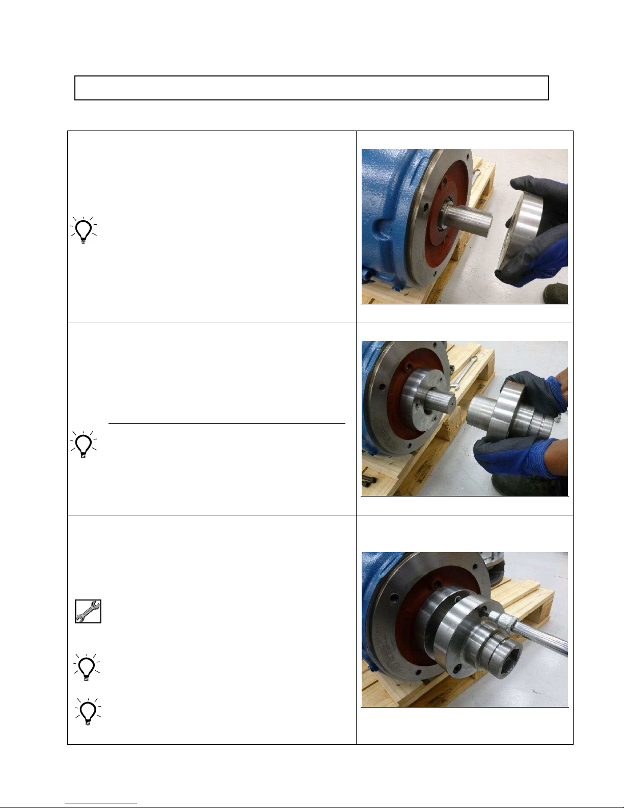
Assembly - Stage 3 – Motor & Motor Support (Close Coupled)
3.01 Fit taper ring part of Drive Adaptor (52.52) over
motor shaft.
Ensure taper is correct way round to match taper on
Drive Adaptor body.
Apply anti-seize compound to bore of taper ring.
3.02 Fit Drive Adaptor to motor shaft.
Push Drive Adaptor (52.52) on to motor shaft.
Shaft end must bottom out in bore of Drive Adaptor
for correct axial positioning.
Use a soft mallet to tap the end of Adaptor to
ensure shaft has bottomed.
Apply anti-seize compound to motor shaft.
3.03 Fit Draw Screws (52.S42) and tighten evenly to
draw taper ring towards flange.
This will cause Drive Adaptor to grip motor shaft.
Leave final tightening for next step.
IEC Motors – 8 mm Hex
NEMA 143TC to 215TC – 7/32” Hex
NEMA 254TC to 365TSC – 5/16” Hex
Apply anti-seize compound to thread of Draw
Screws.
A large screw driver or similar tool can be used
behind the flange between one of the screws and
the Drive Adaptor body to prevent the Drive Adaptor
from turning
SA-07-11-92, Rev Orig 84 October 2015
Page 92

Assembly – Stage 3 – Motor & Motor Support
3.04 Attach magnetic base to front face of motor to
check run-out of Drive Adaptor (52.52).
Set Dial Test Indicator to run in front bore which is
the location for Outer Magnet Ring (51.51).
Tighten Retention Screws (52.S42) in a sequence
that will keep run-out within limits.
Maximum allowable run-out 0.075 mm
(0.003”)
IEC 90 to 250 – 8 mm Hex – 75 Nm (55 lbf-ft)
143TC to 215TC – 7/32” Hex – 35 Nm (26 lbf-ft)
254TC to 365 TSC – 5/16” Hex – 60 Nm (44 lbf-ft)
3.05 Fit 2 off Eye Bolts and suitable lifting gear to tapped
holes in any two adjacent webs of Motor Adaptor
(45.45).
2 x 5/8” Eye Bolts for NEMA Motors
2 x M16 Eye Bolts for IEC motors
3.06 NEMA Motors
NEMA motors are face mounted, an Adaptor Plate
(45.16) will always be mounted to the front face of
the NEMA motor.
Fit Adaptor Plate (45.16) to front face of motor.
3.07 NEMA Motors
Fit retention Screws (45.S42) and tighten down
evenly from side to side.
SA-07-11-92, Rev Orig 85 October 2015
Page 93
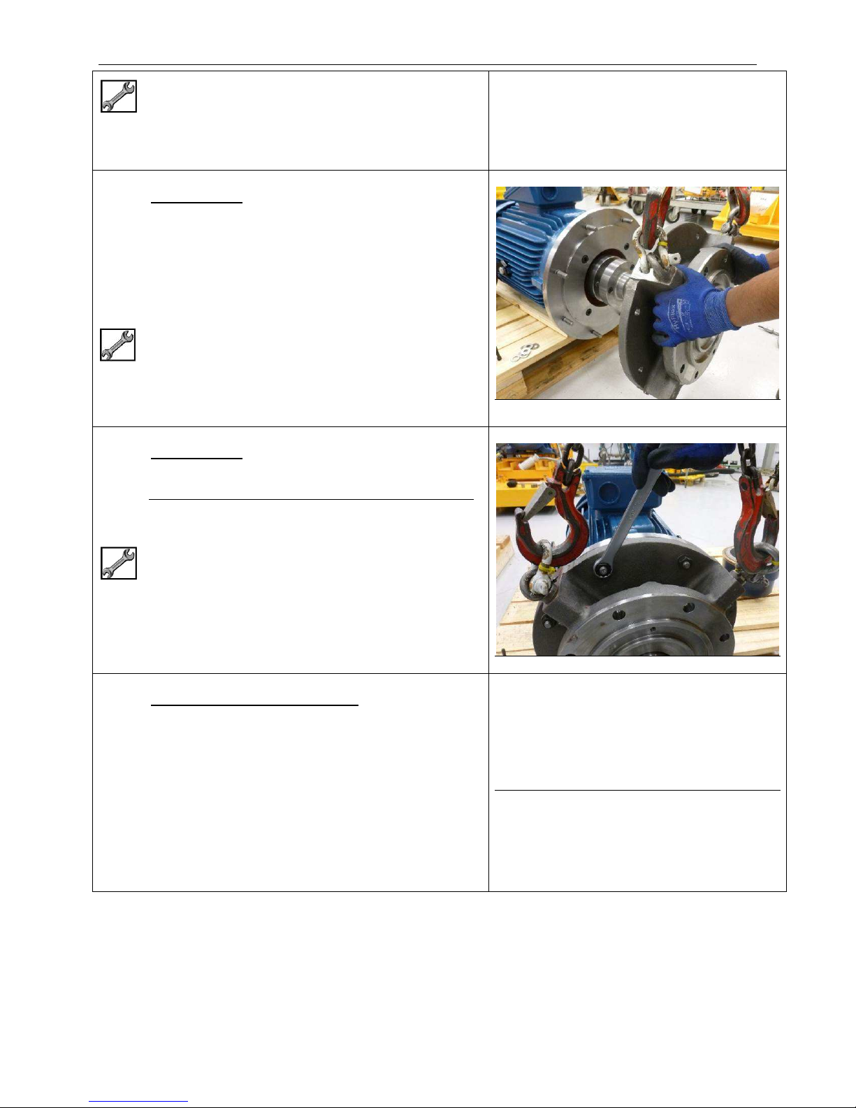
143TC to 145TC – 5/16” Hex – 60 Nm (44 lbf-ft)
182TC to 286TSC – 3/8” Hex – 150 Nm (111 lbf-ft)
324TC to 365TSC – ½” Hex – 280 Nm (206 lbf-ft)
3.08 NEMA Motors
Fit Eye Bolts and suitable lifting gear to webs of
Motor Adaptor (45.45).
Position motor terminal box at 12 o’clock and fit
Motor Adaptor to Adaptor Plate (45.16).
2 x 5/8” Eye Bolts for NEMA Motors
2 x M16 Eye Bolts for IEC motors
3.09 NEMA Motors
Assembly – Stage 3 – Motor & Motor Support
Fit Retention Nuts (45.N15) and Washers
(45.W15).
Tighten evenly from side to side.
¾” A/F – 100 Nm (74 lbf-ft)
3.10 IEC Motors WITH Adaptor Plate
A separate Adaptor Plate (45.16) is only required
for the largest motors.
Fit Adaptor Plate (45.16) to motor.
No image available
SA-07-11-92, Rev Orig 86 October 2015
Page 94
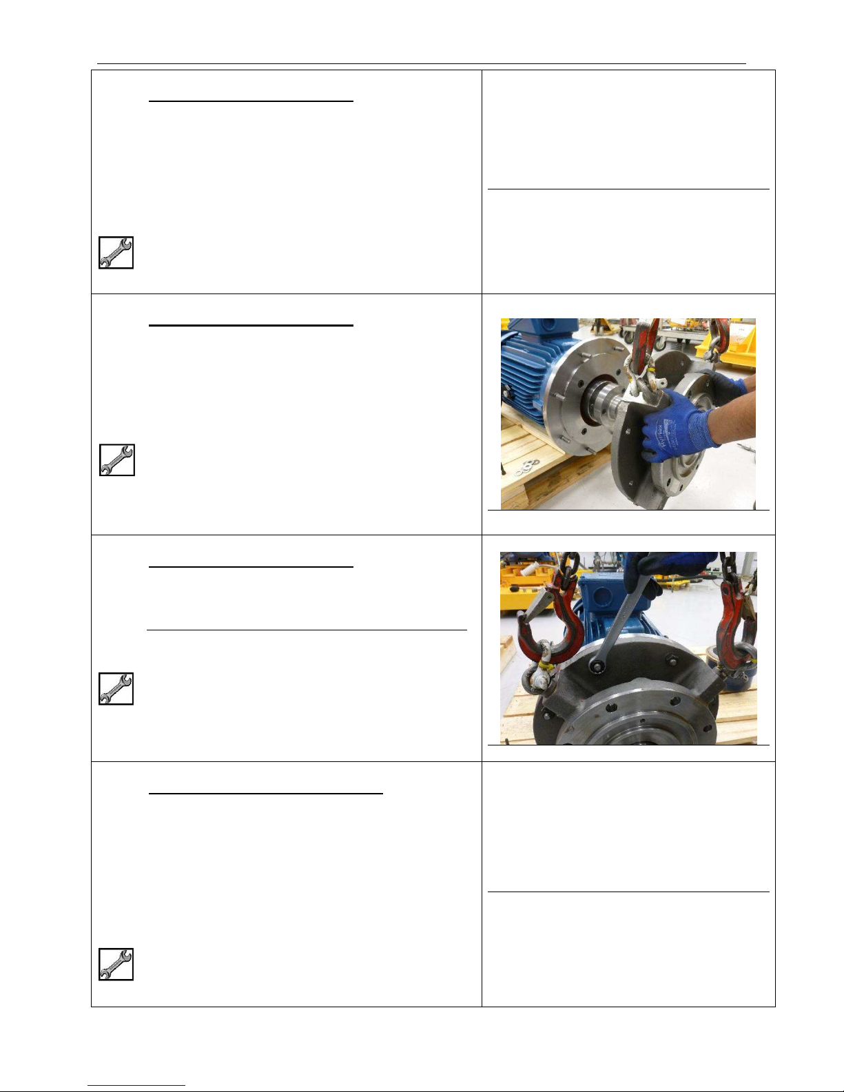
Assembly – Stage 3 – Motor & Motor Support
3.11 IEC Motors WITH Adaptor Plate
Fit retention Screws (45.S42) and Washers
(45.W15).
Tighten down evenly from side to side.
250 Frame motor with require addition of Nuts
(45.N15) and Washers (45.W15).
24 mm AF
185 Nm (136 lbf-ft)
3.12 IEC Motors WITH Adaptor Plate
Fit 2 off Eye Bolts and suitable lifting gear to any
adjacent webs of Motor Adaptor (45.45).
Position motor terminal box at 12 o’clock.
Fit Motor Adaptor to Adaptor Plate (45.16).
No image available
M16 Eye Bolts x 2
3.13 IEC Motors WITH Adaptor Plate
Fit Retention Nuts (45.N15) and Washers
(45.W15).
Tighten evenly from side to side.
15/16” AF
200 Nm (147 lbf-ft)
3.14 IEC Motors WITHOUT Adaptor Plate
IEC motors are flange mounted, in most cases an
Adaptor Plate will not be required.
Fit 2 off Eye Bolts and suitable lifting gear to any
adjacent webs of Motor Adaptor (45.45).
Position motor terminal box at 12 o’clock.
No image available
Fit Motor Adaptor (45.45) directly to motor flange.
M16 Eye Bolts x 2
SA-07-11-92, Rev Orig 87 October 2015
Page 95
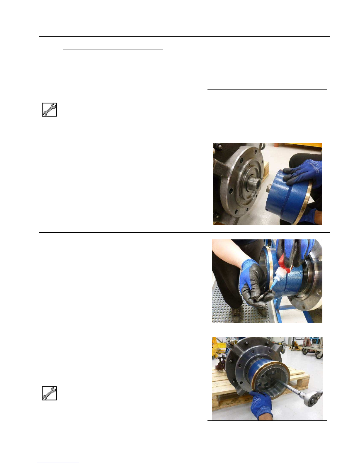
Assembly – Stage 3 – Motor & Motor Support
3.15 IEC Motors WITHOUT Adaptor Plate
Fit Screws (45.S42) and Washers (45.W15) that
retain Motor Adaptor (45.45) to motor.
Frame 225 2 pole motor will also require Nuts
(45.N15) and Washers (45.W15).
Tighten evenly from side to side.
IEC 90 – 17 mm AF – 45 Nm (33 lbf-ft)
IEC 100 to 132 – 19 mm AF – 75 Nm (55 lbf-ft)
IEC 160 to 225 – 24 mm AF – 185 Nm (136 lbf-ft)
3.16 Line up screw holes and fit Outer Magnet Ring
(51.51) to hexagon drive of Drive Adaptor (52.52).
No image available
3.17 Add one drop of Loctite 242 Threadlocker (or
similar product) to each of the Outer Magnet Ring
Retention Screws (52.S41).
3.18 Fit 2 off Retention Screws (52.S41) through Outer
Magnet Ring (51.51) and tighten.
¼” Hex
25 Nm (18 lbf-ft)
SA-07-11-92, Rev Orig 88 October 2015
Page 96
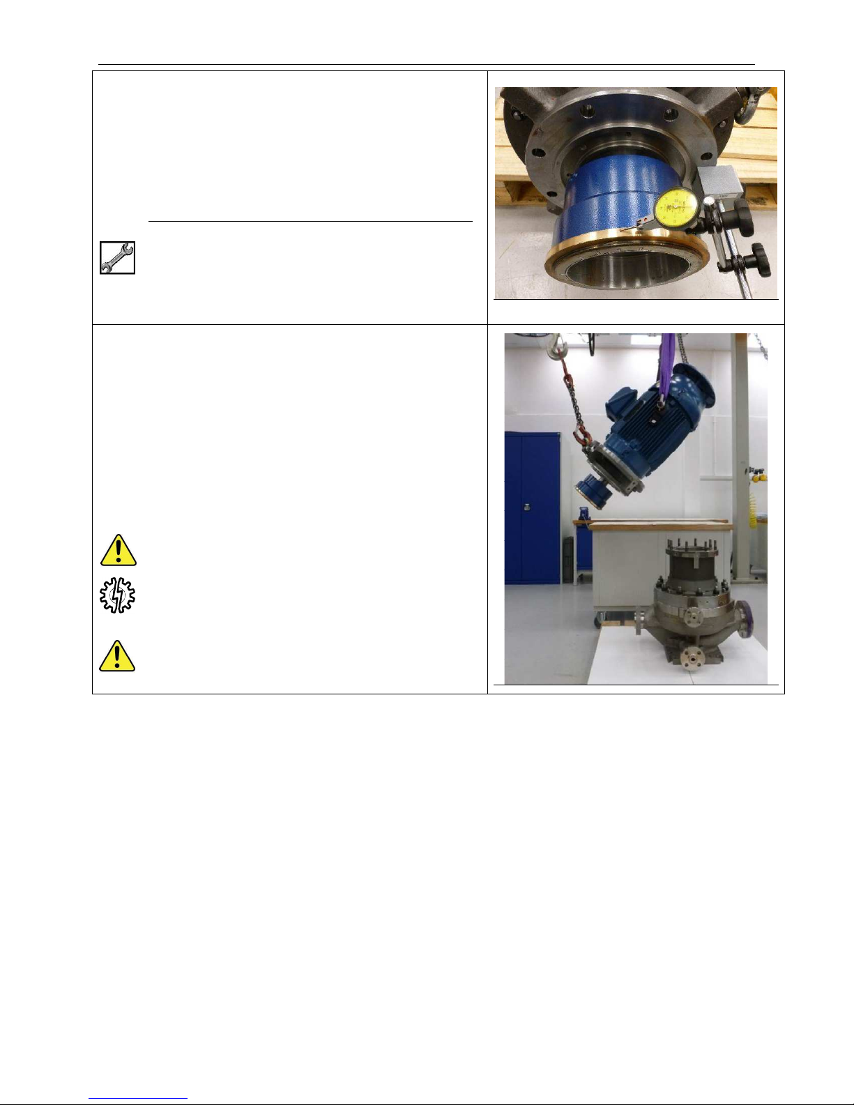
Assembly – Stage 3 – Motor & Motor Support
3.19 Set magnetic base on mounting face of Motor
Adaptor (45.45).
Check run-out of Bump Ring at front end of Outer
Magnet Ring (51.51).
Maximum allowable run-out 0.25 mm
(0.010”)
If run-out is high, remove Outer Magnet Ring, rotate
through 180° and re-fit.
Re-check run-out.
3.20 Attach one lifting device to Eye Bolts already fitted
to Motor Adaptor (45.45).
Attach second lifting device to lifting eyes either
side of Electric Motor.
Initially lift Motor Assembly horizontally and then
lower Motor Adaptor completely so assembly is
suspended vertically by the Motor only.
Remove lifting gear attached to Motor Adaptor.
Ensure motor lifting eyes are capable of lifting the
additional weight of Motor Adaptor (45.45), Drive
Adaptor (54.54) and Outer Magnet Ring (51.51).
The extra weight is shown on customer specific
installation drawing under Motor Adaptor weight.
DO NOT LIFT COMPLETE PUMP WITH LIFTING
EYES OF ELECTRIC MOTOR.
SA-07-11-92, Rev Orig 89 October 2015
Page 97
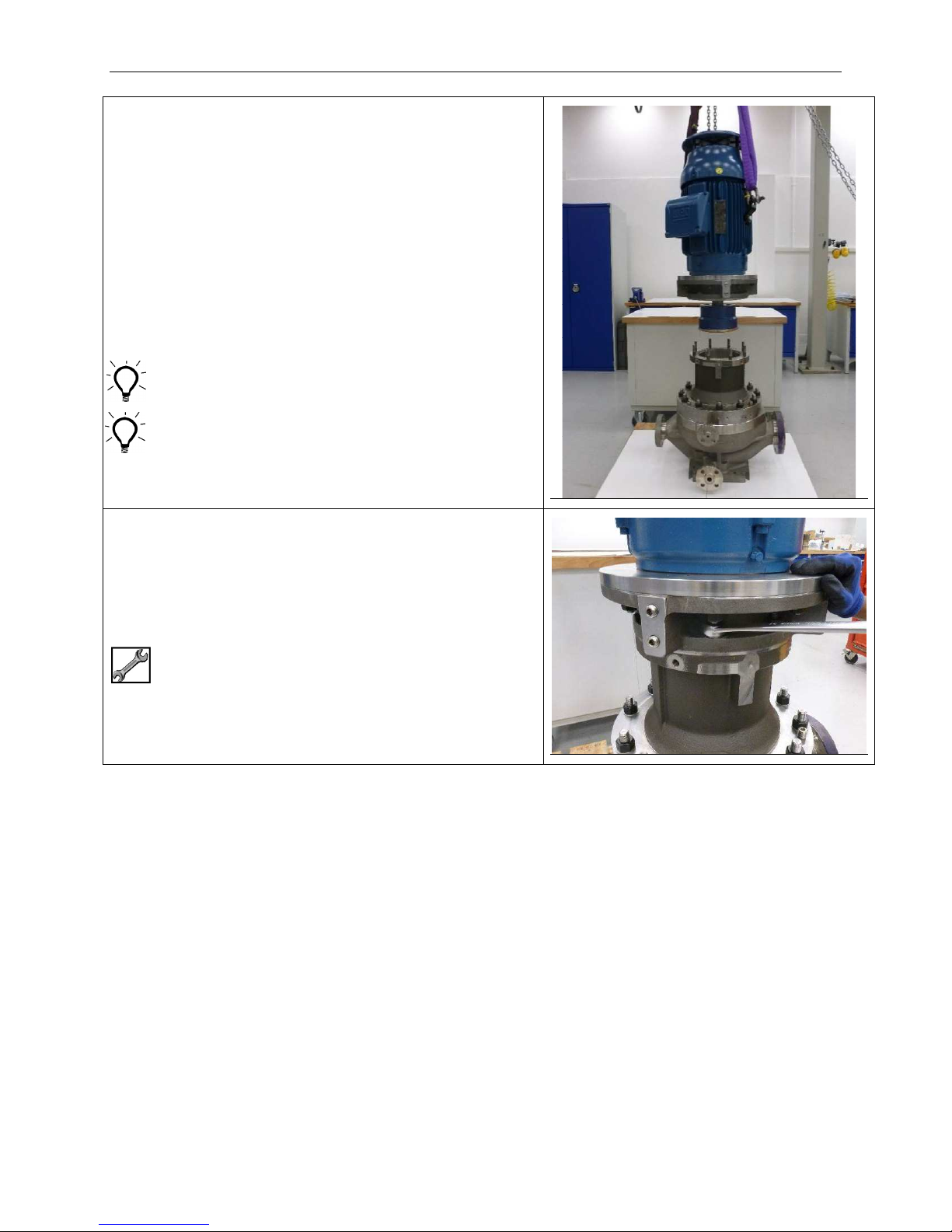
Assembly – Stage 3 – Motor & Motor Support
3.21 Position motor terminal box relative to pump
nozzles and lower Motor Assembly onto Coupling
Housing (43.43).
Guide Outer Magnet Ring (51.51) into Coupling
Housing and over Containment Shell (20.20).
Ensure assembly is suspended vertically before
lowering.
Avoid bumping Outer Magnet Ring as run-out of
Outer Magnet Ring may be affected.
3.22 Remove Eye Bolts and lifting gear from Motor
Adaptor (45.45)
Fit retention Nuts (43.N13) and Washers (43.W14)
to Studs (43.48B) of Coupling Housing (43.43).
15/16” Ring attachment for torque wrench
125 Nm (92 lbf-ft)
SA-07-11-92, Rev Orig 90 October 2015
Page 98
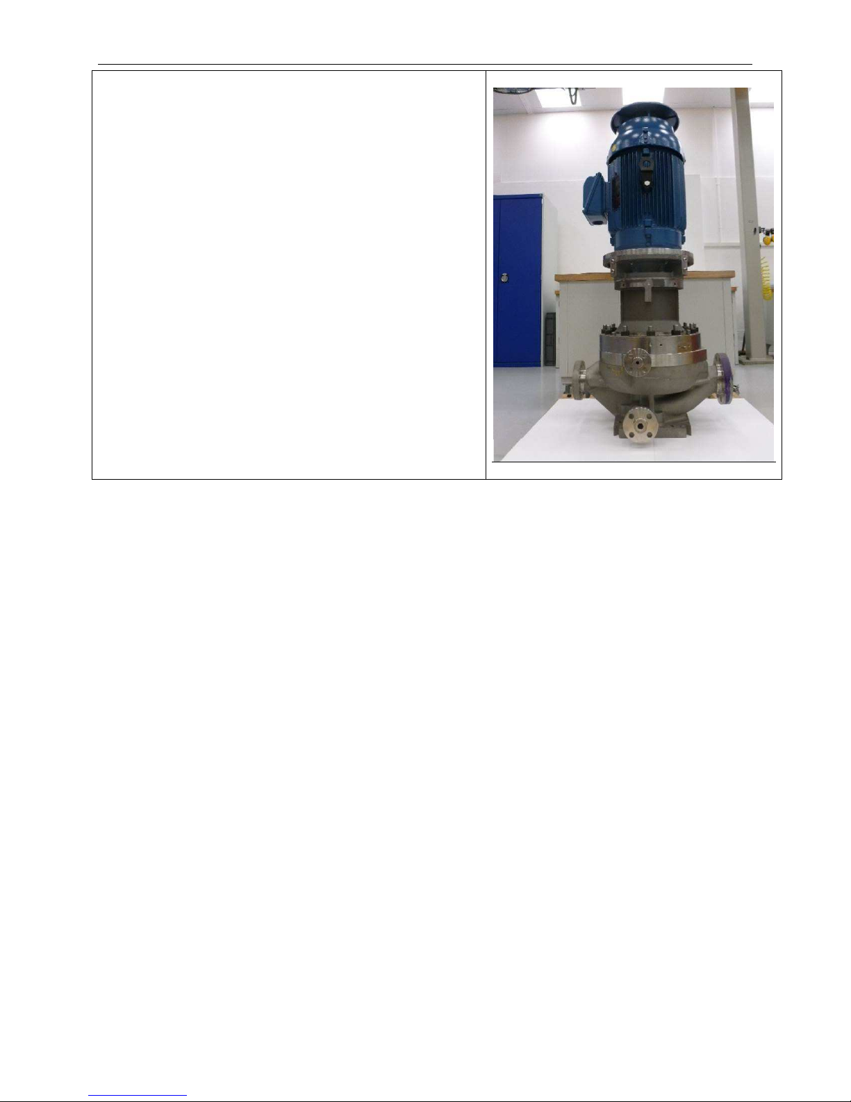
Assembly – Stage 3 – Motor & Motor Support
3.23 Remove lifting gear from motor.
Pump is now fully assembled and ready to be reinstalled into pipework.
SA-07-11-92, Rev Orig 91 October 2015
Page 99
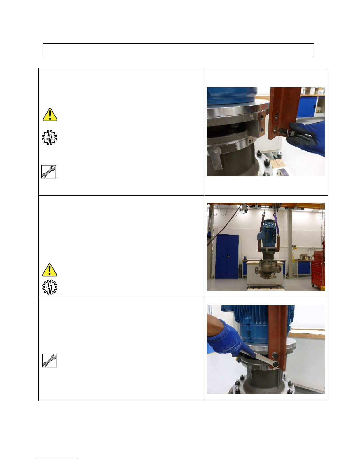
Assembly - Stage 4 – Re-Install Pump
4.01 Fit lifting lugs (98.98) to motor Adaptor (45.45) with
High Tensile Retention Screws (98.S11) and
Washers (98.W11).
Each new pump is furnished with the above lifting
equipment.
2 off Lifting Lugs for pumps up to 750 kg (1650 lbs).
4 off Lifting Lugs for pumps over 750 kg (1650 lbs).
Lifting Lugs are only certified to the weight marked
when used with Retention Screws supplied.
15/16” AF for NEMA motors
24 mm AF for IEC motors
125 Nm (92 lbf-ft) (NEMA & IEC)
4.02 Complete pump should be lifted with Lifting Lugs
(98.98) that were originally supplied with the pump.
Fit suitable lifting gear to Lifting Lugs (98.98) and
take up any slack to prevent toppling of pump.
Remove fixing down screws if used.
Lift pump away and re-fit to pipework.
Re-fit orifice plate if necessary.
Securely fasten pump to suitable base during
transport.
4.03 Remove Retention Screws (98.S11), Washers
(98.W11) and Lifting Lugs (98.98) from Motor
Adaptor (45.45).
15/16” AF for NEMA motors
24 mm AF for IEC motors
SA-07-11-92, Rev Orig 92 October 2015
Page 100
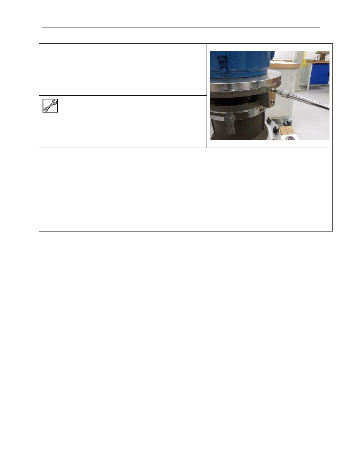
Assembly – Stage 4 – Re-Install Pump
4.04 Re-fit grub screws (45.S53) to webs of Motor
Adaptor (45.45).
This will prevent corrosion of retention holes for
Lifting Lug fasteners.
5/16” Hex
Hand tight
Pump is now ready for commissioning
Refer to Installation & Operating Manual for correct venting and start-up procedure.
SA-07-11-92, Rev Orig 93 October 2015
 Loading...