


SUNDYNE
LMV-801 PUMPS
Instruction and Operation Manual
January 2009
14845 W. 64th Avenue • Arvada, Colorado 80007 USA • +1-303-425-0800 • FAX: +1-303-425-0896 • www.sundyne.com
Sundyne Europe • Dijon (Longvic) • France • +33 (0) 3.80.38.33.00 • FAX: +33 (0)3.80.38.33.66
Sundyne Nikkiso • 27-10, Ebisu 2-Chome, Shibuya-Ku • Tokyo 150-0013, Japan • +81-3-3444-6475 • FAX: +81-3-3444-6806
ANSIMAG • ANYSPEED • CASTER • GSP • HMD/KONTRO • MASO/SINE • SUNDYNE COMPRESSORS • SUNDYNE • SUNFLO

Copyright
All rights reserved. No part of this publication may be reproduced, stored in a retrieval system or transmitted in any
form or by any means, electronic, mechanical, photocopying, recording or otherwise without the prior permission of
Sundyne Corporation.
© 2009 Sundyne Corporation
Warranty
Sundyne Corporation warrants to Buyer for a period of twelve (12) months from the date of being placed in service
(but not to exceed eighteen (18) months after the date of shipment) that the equipment at the time of shipment will
be free from defects of design, material and workmanship. If any defect s or m a lperformance occur during the
warranty period, Sundyne’s sole obligation shall be limited to alteration, repair or replacement at Sundyne’s
expense, F.O.B. Factory, of parts or equipment, which upon return to Sundyne and upon Sundyne’s examination
prove to be defective. Equipment and accessories not manufactured by Sundyne are warranted only to the extent of
and by the original manufacturers’ warranty. Sundyne shall not be liable for damage or wear to equipment caused by
abnormal conditions, vibration, failure to properly prime or to operate equipment without flow or caused by
corrosives, abrasives or foreign objects. THE FOREGOING WARRANTY IS EXCLUSIVE AND IN LIEU OF
ALL OTHER WARRANTIES, WHETHER EXPRESSED OR IMPLIED INCLUD I NG AN Y WARRANTY OF
MERCHANTABILITY OR FITNESS FOR ANY PARTICULAR PURPOSE. In no event shall Sundyne be liable
for consequential or incidental damages.
14845 W. 64th Avenue • Arvada, Colorado 80007 USA • +1-303-425-0800 • FAX: +1-303-425-0896 • www.sundyne.com
Sundyne Europe • Dijon (Longvic) • France • +33 (0) 3.80.38.33.00 • FAX: +33 (0)3.80.38.33.66
Sundyne Nikkiso • 27-10, Ebisu 2-Chome, Shibuya-Ku • Tokyo 150-0013, Japan • +81-3-3444-6475 • FAX: +81-3-3444-6806
ANSIMAG • ANYSPEED • CASTER • GSP • HMD/KONTRO • MASO/SINE • SUNDYNE COMPRESSORS • SUNDYNE • SUNFLO

Contents
CONTENTS .........................................II
INTRODUCTION.................................. 1
Sundyne Centrifugal Pumps .............. 1
Extended Motor Shaft Option............. 1
Text Symbols ......................................... 1
Equipment and Safety Precautions.. 2
Wearing Personal Protective
Equipment .............................................2
Using Forklifts....................................... 2
Ensuring Electrical Safety................... 2
Testing Equipment............................... 2
Using Chemicals .................................. 3
Protection from Falling ........................ 3
Preventative Machine Guards............ 3
EXPLOSION/FIRE HAZARD.............. 3
Pre-Commission Checklist ................. 3
Familiarizing Yourself with the Pump 3
Driver Instructions................................ 3
Verifying Auxiliaries.............................. 3
Installing a Seal Environmental
Control System..................................... 4
Checking Driver Rotation.................... 4
Piping Connections.............................. 4
Storing Your Pump Long-Term ..........6
Suction and Discharge Piping............7
Seal Environmental Control System.7
Liquid Buffer System............................8
START UP ........................................... 9
Start-Up Procedures .............................9
Controlling the Pump During Startup9
Single Operation................................... 9
Parallel Operation................................. 9
OPERATION & CONTROL................ 10
Operation of Sundyne Pumps
Suction Conditions............................. 10
Minimum Flow Conditions................. 10
Entrained Gases................................. 10
System Head Curve........................... 10
Parallel Operation............................... 11
MAINTENANCE................................. 12
Disassembling the LMV-801..............12
..........10
Start Up Checklist................................. 4
Pressurizing the Fluid Loop................ 4
Setting the Valves................................ 4
Control Checklist................................... 4
Verifying Operating Conditions.......... 4
Installation and Start-Up Checklist... 5
INSTALLATION................................... 6
Inspection ............................................... 6
Storing Your Pump Short-Term......... 6
Sundyne Corporation http://www.sundyne.com
Inspection, Cleaning, & Shimming the
Extended Motor Shaft.........................15
Shaft and Lip Seal.............................. 15
Extended Motor Shaft - Shoulder
Dimension............................................ 15
Shaft Sleeve........................................ 16
Mechanical Seal................................. 16
Reassembling the LMV-801...............17
TROUBLESHOOTING.......................21
Pump Diagnostics ...............................21
ii

Pump Mechanical Seal Diagnostics 23
SPECIFICATIONS.............................25
Common Parts List..............................26
Single Seal Arrangement and Parts.27
Double Seal Arrangement and Parts
..................................................................29
Tandem Seal Arrangement and Parts
..................................................................31
Inducer & Parts.....................................33
Diffuser Cone Extension....................34
Integral Centrifugal Separator..........35
Extended Motor Shaft Adapter.........36
Recommended Spare Parts List.......37
INDEX................................................40
Sundyne Corporation http://www.sundyne.com
iii
Instruction and Operation Manual
INTRODUCTION
Sundyne Centrifugal Pumps
Sundyne pumps provide high-energy
performance and competitive efficiencies in an
industrial quality, compact unit that is simple to
maintain. Sundyne pumps are single stage.
Designed to increase the pressure of a
continuous flow of fluid by applying centrifugal
action, Sundyne pumps are most commonly
used in HPI, CPI, and Boiler Feed applications.
Commonly applied in refineries, petrochemical
plants, and power generation plants, Sundyne
pumps are used in high-head, low-to-medium
flow processes. This manual presents
installation, servicing, troubleshooting,
maintenance, and spare parts information for the
latest configuration of Sundyne centrifugal
pumps.
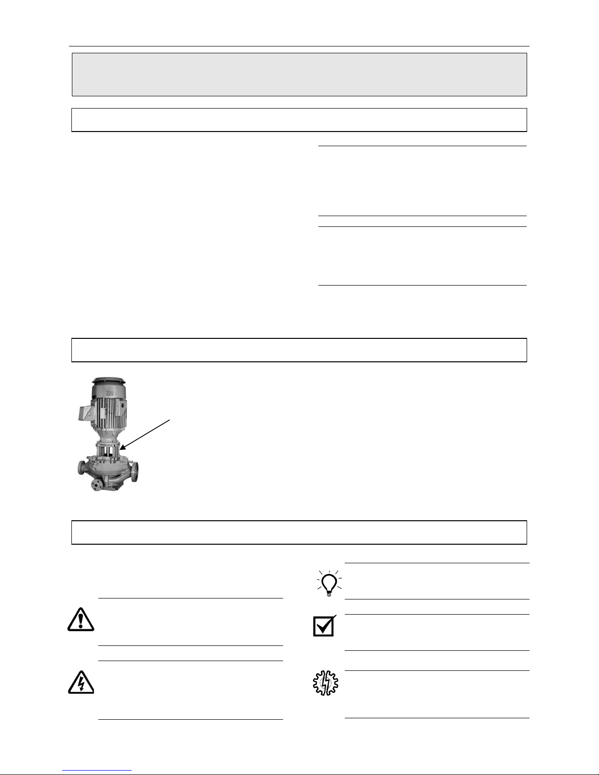
Extended Motor Shaft Option
Adapter for extended
motor shafts
Note: Parenthetical numbers included in the
text correspond to item numbers on the
illustrated figures. The correct spare
part can be ordered for any generation
pump by referencing the item and serial
numbers.
Note: If the pump has a bearing box, the
instructions are in a separate manual.
The bearing box manual and the pump
manual are designed to be used
together.
Sundyne offers an extended motor shaft for use in
extreme temperature conditions. The extended motor
shaft and motor adapter separate the motor from the
pump. This option is recommended when the process
temperature is below 0° F (-18° C) or above 300° F
(149° C). This option can be utilized on existing units
through a field retrofit.
Text Symbols
The following symbols may be found in the text
of this manual. They have the following
meanings:
WARNING: Text accompanied by this
symbol indicates that failure to follow
directions could result in bodily harm or
death.
ELECTRICAL HAZARD: Text
accompanied by this symbol indicates
that failure to follow directions could result
in electrical damage to equipment or
electrical shock.
RECOMMENDED: Text accompanied by
this symbol indicates recommended
usage.
REMINDER: Text accompanied by this
symbol indicates a reminder to perform
an action.
EQUIPMENT USE ALERT: Text
accompanied by this symbol indicates
that failure to follow directions could result
in damage to equipment.
1

Instruction and Operation Manual
Equipment and Safety Precautions
Sundyne Corporation manufactures centrifugal
pumps to exacting International Quality
Management System Standards (ISO 9001) as
certified and audited by Lloyd’s Register Quality
Assurance Limited. Genuine parts and
accessories are specifically designed and tested
for use with these products to ensure continued
product quality and performance. Sundyne
cannot test all parts and accessories sourced
from other vendors, incorrect design and/or
fabrication of such parts and accessories may
adversely affect the performance and safety
features of these products. Failure to properly
select, install or use authorized Sundyne pump
parts and accessories is considered misuse and
damage or failure caused by misuse is not
covered by Sundyne’s warranty. Additionally,
modification of Sundyne products or removal of
original components may impair the safety of
these products and their effective operation.
CAUTION
Sundyne pumps may handle hazardous,
flammable, and/or toxic fluids. Proper personal
protective equipment should be worn.
Precautions must be taken to prevent physical
injury. Pumpage must be handled and disposed
of in accordance with applicable environmental
regulations.
Note: Safety procedures must be applied
prior to any installation, maintenance,
or repair of a Sundyne pump. Failure to
follow safety precautions may lead to
injury!
Wearing Personal Protective
Equipment
To ensure safety, protective equipment must be
worn at all times when installing, performing
maintenance or repairing equipment. The
following safety recommendations must be
adhered to for optimum safety:
• Hearing protection is strongly
recommended at all times when noise
levels exceed 85 dB during an eight
(8.0) hour period.
Note: Chemical resistant gloves must be used
if chemical use is required (refer to
Using Chemicals for additional
information).
Note: A dust mask respirator must be worn if
chemicals have warning labels
regarding fumes, dust or mists.
When using more than one piece of protective
equipment, consider their compatibility. For
example, safety glasses will not interfere with
hearing protection seals. Be sure to clean all
pieces of personal protective equipment
immediately after each use.
Using Forklifts
Any persons operating a forklift must have an
active recognized operator license.
Note: Before initializing forklift operation,
verify that the lift is in a safe operating
position.
Ensuring Electrical Safety
All electrical sources must be powered-off
before installation, service or repair of
equipment occurs.
Note: Sundyne recommends that a Lock-
out/Tag-out program be followed prior
to altering the equipment. Locks or
tags must be provided to warn
employees that equipment is
temporarily unavailable.
Once all work has been completed, the person
installing the lock or tag must remove it
according to company procedure.
• Safety glasses, with the minimum
requirement of side shields, must be
worn at all times.
• Steel-toed shoes must be worn when
lifting equipment greater than 15 pounds
(7 kg) or if pallet jacks or forklifts are
operated.
Testing Equipment
Prior to performing a test on newly installed,
maintained or repaired equipment, all personnel
in the immediate area must be warned.
Note: Follow company procedures prior to
equipment testing at all times.
2

Instruction and Operation Manual
Using Chemicals
Any chemicals to be used must be accompanied
by a relevant material safety data sheet (MSDS),
in accordance with government legislation. If
applicable, use chemical proof gloves.
Note: An eye wash station (or equivalent)
should be available in the event of
injury. If any hazardous or flammable
chemicals pass through the equipment,
a complete decontamination of the
equipment is required.
Protection from Falling
Fall protection and associated preventative
measures is required when working on
equipment located six feet or higher from the
ground.
Note: Follow company fall prevention
procedures prior to working on
equipment.
Preventative Machine Guards
Preventative guards must remain in place on all
equipment.
Note: Only remove the guards while
performing maintenance or repair.
Replace the guards immediately after working
on the equipment and prior to start up.
EXPLOSION/FIRE HAZARD
Note: Never use an acetylene torch, open
flame, or heat to attempt to remove
parts that have seized together in
Sundyne equipment. Any residual
process gas or liquid that is flammable
can result in an explosion or fire with
potential for serious injury or death.
Pre-Commission Checklist
Familiarizing Yourself with the Pump
Before servicing and starting up the Sundyne
pump, carefully review all information on the
product, including:
• Specification sheets
• Outline drawings
• Performance curves
• Instruction and related manuals
• System P&ID/Process Flow Diagram
(Clients equipment)
• Control system and operational
philosophy/narrative (Client)
Familiarize yourself with the pump configuration
before starting and operating the pump.
Driver Instructions
Carefully follow all installation and starting
instructions provided by the driver manufacturer.
This information is included in the final data
package.
Verifying Auxiliaries
Before start up, verify that the following
auxiliaries are met:
• Check the utility connections
• Verify that the auxiliary piping conforms
to Sundyne standards, as indicated in
the detailed specifications
• Verify all switch and instrument
connections
• Verify that all switch and instrument
settings are set to normal operating
standards
• Calibrate all measurement equipment,
such as flow meters, ampere meters,
and pressure meters, etc.
3

Instruction and Operation Manual
Installing a Seal Environmental Control
System
Install a system to control the seal environment.
Also, verify that port 1 is properly vented.
If required, install drain piping overhead to
ensure that the environment operates under
normal conditions. For more information,
contact Sundyne Corporation.
Checking Driver Rotation
Rotation must be counter-clockwise when
looking at the end of the motor.
Start Up Checklist
Pressurizing the Fluid Loop
Pressurize the double seal buffer loop or
external seal flush, if applicable, prior to
admitting fluid into the pump casing.
Piping Connections
Verify that the following bolted or threaded
connections are tight:
• Pump flange bolts
• Seal environment piping and port
connections
• Pump case drain plug
Setting the Valves
To set the pump to the designated operating
point, start the pump with the suction valve in
the open position while throttling the discharge
valve.
Control Checklist
Verifying Operating Conditions
Verify the following parameters against the
specifications on the Specification sheet:
• Suction pressure
• Suction temperature
• Discharge pressure
• Total head
• Flow rate
• Power consumption
• Specific gravity
• Viscosity
• Net Positive Suction Head (NPSH)
The status of these conditions will significantly
alter performance of the pump if they are not in
accordance with the specification sheet.
Check with your Sundyne representative if the
operation conditions of your pump must run
under different parameters than indicated by the
specification sheet.
4

Instruction and Operation Manual
Installation and Start-Up Checklist
Note: Lock out all switch gears, including main driver, and instrumentation before working on this
equipment.
This checklist is NOT intended to be inclusive. You must read and follow: instruction manuals, outline
drawings, specification sheets and curves for this equipment during installation, commissionin g, and
operation. Your total satisfaction is our goal. Please call with any questions or comments. Be sure to have
the unit serial number that is imprinted on the pump nameplate, and request “Sundyne Field Service”.
Is all the information underlined above readily available?
Are the following bolted/threaded connections tight?
• Pump flange bolts?
• Seal environment piping and port connections?
• Pump case drain plug?
Is a check valve installed in the discharge line?
Is Port 1 open to atmosphere, or piped to safety drain or flare vent header? (Back pressure must
not exceed 5 psig).
Note: A drip leg must be used if the Port 1 connection rises from the seal housing.
Are all other seal system ports identified and connected according to the outline drawings?
Do process conditions, suction pressure, suction temperature, discharge header pressure, and
specific gravity agree with specification sheet information? DO NOT test the pump on water
unless it is designed for water. Check with your representative or Sundyne Corporation if you
must test on a different fluid than shown on the specification sheet.
Prior to starting the unit, have you opened the suction valve fully and discharge throttled to allow
design flow, typically 40-50% open? Check the control valve to be sure it is functional. Inspect the
case drain, ports, and flanges for leaks. Has the pump been vented through Port 6. Check suction
pressure to be sure it agrees with the specification sheet.
Unlock the main driver circuit and bump the motor. Rotation is CCW, as viewed from the top end
of the motor. Is rotation correct? Once rotation is verified start the main driver. After
commissioning, bumping the motor is not required.
If pressure control is being used, throttle the discharge valve immediately after start-up. Does the
discharge pressure agree with the specification sheet? If flow control is being used, adjust the
valve until flow agrees with the design value listed on the specification sheet.
Listen for any unusual noises or pressure fluctuations.
Note: If you have any questions or concerns about these procedures or the information supplied,
please call your representative or Sundyne Corporation.
5
Instruction and Operation Manual
INSTALLATION
Inspection
Immediately inspect your Sundyne product upon
receipt of the equipment. Check for any
damage, which may have occurred during
shipment. Notify the carrier and Sundyne
immediately if damage is evident.
Storing Your Pump Short-Term
If your Sundyne pump is not to be installed
immediately, protect it from exposure to
moisture and dust. Do not remove the factory
installed shipping covers for casing flanges and
Storing Your Pump Long-Term
In addition to the precautions in the short-term
section above, additional precautions are
required for long-term storage.
If your Sundyne pump will not be operated for a
period of time exceeding six months from the
date of shipment, long-term storage conditions
must be met to ensure minimum corrosion
damage to the fluid-end components.
Note: Sundyne does not accept liability for
equipment damaged during the storage
period. Sundyne does not guarantee
the quality of equipment during and
after the storage period.
To ensure the original quality of the Sundyne
pump after storage, all components must be
inspected by an authorized Sundyne service
engineer. Components that are not
manufactured by Sundyne (except mechanical
seals) must be inspected by its own
manufacturer.
Note: Any inspection fees are the sole
responsibility of the purchaser.
Factors which affect the quality of a Sundyne
pump, when stored, are:
Note: The input shaft on the pump may not
seal ports. Ensure that the shipping covers be
kept securely in place.
Note: Observe the storage instructions
Long-term storage methods must prevent
damaging conditions from making contact with
the internal components of the equipment. When
the equipment is stored in strong chemical
environments or near salt water, protection must
occur immediately upon receipt of the
equipment.
Recommended Long-Term Storage
Procedures
Sundyne recommends that you do the following
to prevent damage to your pump during longterm storage:
1. Store your pump only in an indoor, climate
2. Perform inert gas purging of component
3. Use desiccant bags.
turn freely due to seal drag. If the input
shaft does turn freely, and if rotation is
“not smooth,” damage may have
occurred during shipping.
provided by the driver manufacturer.
• Humidity
• Temperature
• Surrounding chemicals
controlled building. These conditions will
maintain constant temperature and humidity.
internals.
6

Instruction and Operation Manual
Note: Because long-term storage of
equipment is of a highly critical nature,
it is recommended that Sundyne be
Suction and Discharge Piping
Please adhere to the following best practices for
installing and maintaining suction and discharge
piping:
1. Install a suction strainer (12 mesh - .062" or
1.6mm opening) and clean the suction line
prior to starting the pump. This procedure
will protect the impeller from damage by mill
scale, welding slag, or other foreign particles
during initial startup.
Note: Sundyne recommends installation of a
differential pressure instrument across
strainer to indicate strainer condition.
2. When installing piping to the pump, ensure
that all piping is supported independently
from the pump.
3. All piping must always line up with the pump
flanges.
Note: Never use force to position piping into
place at the flanged suction and
discharge connection locations. Failure
to have piping properly aligned may
impose excessive strains on the unit.
contacted to provide more details on
the above procedures.
4. Sundyne recommends using a straight pipe
assembly of at least three times the length
of the pipe diameter.
Note: Carefully select the size of pipe and
fittings to be installed so that friction
losses will remain low.
5. Never use a suction pipe that is smaller in
diameter than the pump suction inlet.
6. Sundyne recommends installation of a
discharge check valve to prevent reverse
rotation.
7. Use block valves (both suction and
discharge) when isolating the pump during
shutdown. This practice will minimize
process leakage and prevent possible
reverse rotation from pump back-flow.
8. It is recommended that suction and
discharge pressure gauges be installed on
any pump that is not flow controlled. If no
flow measuring device is installed there is no
way to determine accurately where on its
curve the pump is operating.
Seal Environmental Control System
A seal environmental control system may be
required depending upon the pump seal
arrangement and application.
Always maintain the pump seal environment as
detailed on the specification sheet that
accompanies each unit.
Note: For most applications, a standard
control system can be obtained from
the factory.
Ensure that the specified seal environmental
control system is properly installed and that the
ports are open (or plugged) as indicated in
Figure 1.
Note: Port 1 must always be open so that it is
free to drain.
7

Instruction and Operation Manual
Figure 1. Seal Housing Port Identification
Liquid Buffer System
For double liquid seals and tandem liquid seals,
a liquid buffer system is used. Introduce the
buffer liquid into port 7, which will flow through
the seal cavity, and out from port 2.
Buffer flow should be 0.5 to 3 gpm (2 to 12
liters/min) with an inlet temperature of 60
o
120
F (16o to 49oC), and inlet pressure as
o
to
indicated on the pump specification sheet. The
liquid must be clean to 5μ microns.
8

Instruction and Operation Manual
START UP
Start-Up Procedures
Perform the following tasks to start the Sundyne
pump.
1. Run-in of pump: If the pump is to be run
under conditions which are considerably
different from those conditions listed on the
spec sheet (such as a change in specific
gravity, suction pressure, flow rate, etc.) the
factory should be consulted to ensure that
the run-in conditions are compatible with the
pump.
2. Check to ensure that the driver has been
serviced per instructions provided by the
driver manufacturer.
3. Auxiliaries - Check utility connections; verify
that auxiliary piping is per Sundyne
drawings; verify switch and instrument
connections and set points; calibrate flow
instruments and other transmitters.
Controlling the Pump During Startup
4. Flushing screens should be installed in all
field assembled piping connections.
5. Check the pump specification sheet and
outline drawings for seal environment
requirements. Be sure seal housing port
piping is properly connected. If double seals
are used, buffer fluid must be pressurized
before suction pressure is applied to the
pump. Port 1 must be open. Maximum
allowable backpressure on port 1 is 5 psig
(0.35 kg/cm²). If port 6 is not used for a seal
flush, it is recommended that a hand bleed
valve be installed at this location. Bleed air
and vapor before starting.
6. Jogging is used to verify proper direction of
rotation for the main driver.
Note: Never start the pump against a closed
discharge valve. Always check to
ensure that the discharge valve is
partially open.
To ensure control of the pump during start up,
follow the start up procedures for your desired
configuration.
Single Operation
1. Start the pump with the suction valve open
while throttling the discharge valve. This will
ensure that the pump will reach the design
flow operating point.
2. If the process fluid is near its vapor
pressure, open the supply vessel seal cavity
vent so that the pump can fill with liquid.
Parallel Operation
To prevent back-flow, place the check valves in
the discharge piping of each pump.
Note: Sundyne recommends installing
separate bypass loops around each
pump for additional operational
flexibility.
1. Start the first unit as described in the
Single Operation instructions.
2. Start the second unit with the bypass
valve set to maintain the flow above
minimum flow.
3. Open the discharge valve on the second
unit so that the design flow of both units
is maintained.
Note: Do not operate the pumps at their peak
head capability.
Sundyne recommends that separate flow
controls be used on each pump to provide a
lower minimum flow range than is achieved by
pressure control.
9
Instruction and Operation Manual
A
y
2
A
OPERATION & CONTROL
Operation of Sundyne Pumps
Under normal operation, several factors must be
taken into consideration to ensure successful
pump operation. Experienced pump operators
will be aware of jeopardizing factors and their
effects.
Suction Conditions
Improper flow of liquid into the impeller is the
most common operational abuse of centrifugal
pumps. Two conditions must exist to prevent
turbulence at the eye of the impeller.
• Proper suction piping, see suction piping
section.
• Liquid reaching the impeller eye must
have enough vapor pressure to prevent
the fluid from flashing to a gas in the
impeller. If this condition occurs, it will
cause cavitation, which can damage the
impeller and inducer. When centrifugal
pumps cavitate the noise sounds like
the pump is “pumping gravel”. In high
speed, single stage pumps, this sound
may not be discernable. Cavitation can
be prevented by maintaining suction
pressure at a high enough level and
suction temperatures low enough to
maintain Net Positive Suction Head
(NPSHa) available greater than Net
Positive Suction Head (NPSHr) required
by the pumps.
Minimum Flow Conditions
Vibration and noise will occur during operation of
centrifugal pumps if either of two conditions
exist:
• Internal flow separations
• Recirculation at low flow conditions
If the operator is noticing excessive noise or
vibration, operation must be suspended until the
cause is determined and corrected. Continued
use may cause damage to the pump.
Resonance in the discharge line can accentuate
noise, vibration, and damage to the pump,
primarily when a control valve is located an
excessive distance downstream from the pump.
Entrained Gases
The head and capacity of centrifugal pumps will
be reduced by gas that is drawn in with the
liquid. Under normal operating conditions,
centrifugal pumps can tolerate up to 2% of gas
(by volume). Entrained gases can cause
damage to mechanical seals with the exception
of double seals. If you have entrained gas,
contact Sundyne for further instruction.
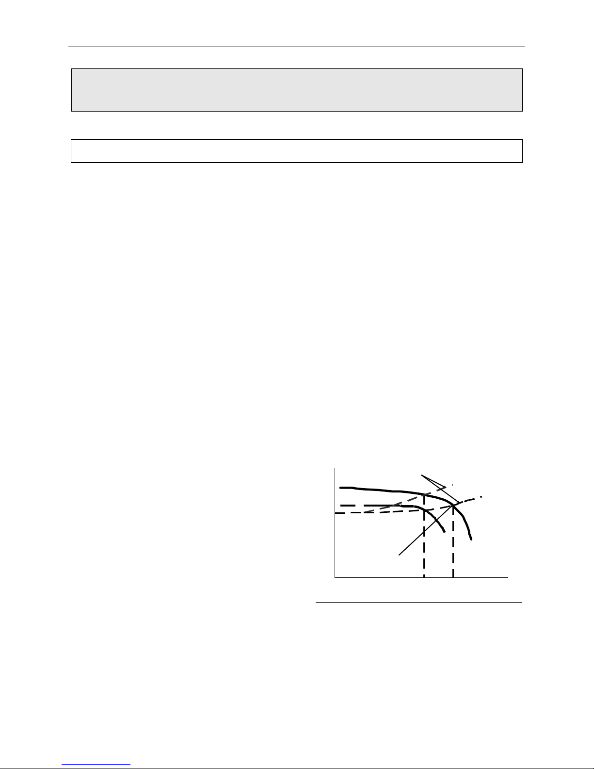
System Head Curve
The point of intersection between the system
curve and the pump characteristic curve
determines the flow or operation for the
centrifugal pump. For steady flow to occur, the
system curve must intersect the pump
characteristic curve at a significant angle. The
following diagram gives examples of satisfactory
and unsatisfactory angles of intersection.
Figure 2. Typical Operation
System (Head) Curves
B
Good
HEAD
ngle of
I ntersection
FLOW
Note: The curve for pump A has a significant
angle of intersection with system curves
D and E. The system curve D could
represent a system with the control
valve wide open while curve E could
represent the same system but with the
throttle valve closed to reduce flow from
flow 1 to flow 2. Pump curve B, on the
other hand, will provide only flow 2,
Valve Partiall
E
1
D
Closed
Valve
Wide
Open
10

Instruction and Operation Manual
even with the control valve wide open
(curve D). When the control valve is
partially closed to create system curve
E, the curve E and lower pump curve B
are practically parallel. The lack of a
significant angle of intersection means
that the system is unstable; pump flow
is likely to fluctuate erratically and not
respond to control valve position.
Parallel Operation
Maximizing control is critical when operating
centrifugal pumps in parallel. One pump can
overpower the other in regards to head at a
lower total flow. If a simple, unrestricted manifold
connects two pumps at the discharge head, the
discharge head of one pump is imposed on the
other. All pumps will see the same discharge
head at a given time. This is demonstrated on
the following diagrams.
The characteristic curves of two pumps
designated A and B are demonstrated in the
Parallel Operation
figure.
Figure 3. Parallel Operation
FLOW
Figure 4. Parallel Units Common Valve
Since no two pumps will have exactly the same
performance, it is assumed that pump A
produces a slight amount more head than pump
B. The pumps are arranged with a common
manifold as shown in Parallel Units Common
Valve figure.
The pressure in the manifold is set at P1; the
flow through pump A indicated as A1 on the
preceding curve. At the same time, the flow
through pump B is indicated as B1. However, if
the throttle valve is closed to cause the manifold
pressure P to rise to P2, then flows through
pump A and B are A2 and B2 respectively. If the
throttle valve were closed even further, then
pump B would cease to flow entirely. Since
pump B would effectively be deadheaded, the
fluid in it would heat up and boil. During internal
boiling, it could encounter liquid slugging and
probable damage to the pump. Proper selection
of a control system can prevent this situation.
11

Instruction and Operation Manual
MAINTENANCE
Disassembling the LMV-801
The following procedures apply to all
configurations of the LMV-801 process pump
including the extended motor shaft and bearing
box options. Refer to the specification sheet to
determine your specific pump configuration and
optional equipment included. Disassembly
should be done only to the extent necessary for
repair.
Note: The following replacement parts will be
required as a result of pump
disassembly and seal housing removal:
PART ITEM NO. QTY.
Impeller Tab washer 5 1
O-ring Repair Kit -- 1
Thermal Barrier Gasket 87A 1
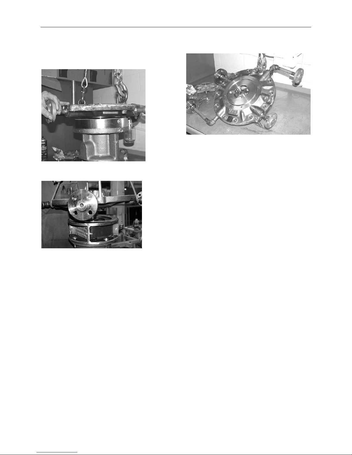
STEP 1
Remove the motor, bearing box and/or extended
motor shaft adapter (if applicable), and seal
housing from the pump casing.
STEP 2
Remove the inducer or impeller bolt.
Note: Left hand thread.
Note: Restricting the impeller from moving will
be necessary.
STEP 3
Remove the impeller by prying gently with two
screwdrivers.
Bearing box
Adapter for
extended
motor shaft
Note: The impeller is dynamically balanced
and should be replaced if it shows any
sign of damage.
12

Instruction and Operation Manual
STEP 4
Remove the diffuser cover.
STEP 5
Remove the lower seal rotating face.
STEP 7
Remove the lower process seal.
STEP 8
Remove the lower shaft sleeve and o-ring.
STEP 6
Remove the lower process seal bolts.
STEP 9
Remove the seal housing bolts.
13
Instruction and Operation Manual
STEP 10
Remove the seal housing from the motor,
bearing box or extended motor shaft adapter,
as applicable.
Seal housing with bearing box shown.
STEP 11
Remove upper process seal or the throttle
bushing.
Seal housing with extended motor shaft
adapter shown.
14

Instruction and Operation Manual
Inspection, Cleaning, & Shimming the Extended Motor Shaft
Shaft and Lip Seal
Inspect the lip seal (115A) and driver shaft for
wear. Replace the lip seal and repair the shaft if
required. Shaft size in the lip riding area to be
1.750 ± 0.003 inches (44.45 ± 0.076mm)
diameter with 16 RMS or better surface finish.
Check the driver shaft for proper axial position.
The shaft shoulder, which controls the position
of the shaft sleeve, seal rotating face and
impeller, must be recessed .092 ± .030 inches
above the flange face as shown in the figure
below. Impeller rub and seal leakage will result if
this dimension is not held.
Figure 5. Driver Shaft Position
Dimension A
Figure 6. Shoulder Dimension
Measure depth A to shaft shoulder
(Range will be 0.068" to 0.108")
Installed adapter housing
A
EXTENDED
SHAFT
MOTOR
(AD02AA21) mounted with
no shims
Number of 0.010”
(0.25mm) Shims
Required
Shims added here
Extended Motor Shaft - Shoulder
Dimension
This section to be used with Reassembling the
LMV-801 section, steps 3 and 4.
The shaft shoulder dimension A as shown in
figure 6 must be measured as described below.
The motor must be positioned vertically with the
shaft pointing upwards.
Measure the shaft shoulder dimension A, from
the face of the motor adapter to the shaft
shoulder. This dimension can be measured
using a parallel bar and depth micrometer or tool
# T-GA-010.
Dimension A is then used to determine the
number of shims required per table in figure 6.
0.098” to 0.108” incl
(2.49mm to 2.74mm incl)
0.088” to 0.097” incl
(2.24mm to 2.48mm incl)
0.078” to 0.087” incl
(1.98mm to 2.23mm incl)
0.068” to 0.077” incl
(1.73mm to 1.97mm incl)
0
1
2
3
15

Instruction and Operation Manual
Shaft Sleeve
Ensure that there are no high spots on the end
surfaces of the shaft sleeve or the impeller hub.
High spots will distort the seal rotating face due
to the clamping force of the impeller bolt. Ensure
that shaft sleeve end faces are parallel within
0.0003” (.0076mm). Shaft sleeve end faces can
be lapped to achieve the flatness required.
Replace or lap the seal rotating face if the wear
track is rough or worn to a depth greater than 2
helium light bands.
A combined total of 0.010 inch (0.25mm)
maximum may be removed from the surfaces of
the seal rotating faces. Excess material removal
will result in incorrect seal face loading causing
increased seal leakage.
Remove any high spots on the end surfaces of
Note: Shaft sleeve ends that are out of parallel
beyond specification can contribute to
mechanical seal leakage due to mating
the shaft sleeve and impeller hub to insure that
the seal rotating face will not be distorted by
clamping force of the impeller bolt.
ring clamped against sleeve being out of
square.
Reassemble the seal, throttle bushing, if used
seal housing, and impeller using an o-ring repair
Mechanical Seal
Carefully inspect the seals for abrasive particles,
excessive seal face wear and any binding of the
seal face washer.
Replace or rebuild a faulty mechanical seal.
Seals may be rebuilt by replacing the seal face
washer, wedge rings, o-ring, and springs. A seal
repair kit is available.
kit. All o-rings that were disturbed by
disassembly should be replaced. During
reassembly, carefully check the torque values
listed in Table 3.
The impeller may rub on the diffuser cover plate
(15) until o-rings (936D and 936E) are
compressed by tightening hex nuts (914A).
Check the shaft for freedom of rotation after the
pump is assembled and all bolts are tightened
per Table 3.
16

Instruction and Operation Manual
Reassembling the LMV-801
The following procedures apply to the LMV-801
process pump single seal arrangement. For
differences in the double and tandem seal
arrangements see the seal arrangement
drawings later in this manual. Refer to the
specification sheet to determine your specific
pump configuration and optional equipment
included.
STEP 1
Install throttle bushing.
STEP 2 (Extended shaft motors only)
Mount the adapter to the motor.
Note: Ensure there are no shims or thermal
barrier gaskets between the motor and
the adapter.
STEP 3 (Extended shaft motors only)
Check the shaft shoulder dimension to
determine number of shims required.
See previous section and figure 6, for method
and table to determine the correct number of
shims.
STEP 4 (Extended shaft motors only)
Install the alignment pin into the adapter. Install
thermal barrier gasket and shims as required.
Alignment pin
Torque bolts to 40 ft-lb.
Installing the shim.
17

Instruction and Operation Manual
STEP 5
Install shaft sleeve on motor, bearing box or
extended shaft motor adapter, as applicable.
STEP 6
Install the thermal barrier gasket (if not
previously installed) and seal housing on the
bearing box or extended shaft motor adapter.
Torque to 40 ft-lbs.
STEP 7
Install the lower shaft sleeve o-ring.
STEP 8
Install the lower process seal and bolts.
Seal housing being installed onto bearing box.
Seal housing being installed onto extended
motor shaft adapter.
Lower process seal.
Tightening the bolts on the lower process seal.
18

Instruction and Operation Manual
STEP 9
Install the lower seal rotating face.
STEP 10
Install the inducer cover and o-rings, 936D and
936E.
STEP 11
Install the inducer or impeller bolt and 936G oring.
STEP 12
Install diffuser and o-rings 936B and 936C.
STEP 13
Install the seal housing and bearing box or
extended motor shaft adapter (as applicable)
onto the pump casing.
Pump, seal housing, and bearing box shown.
Torque impeller or inducer to 36-40 ft-lbs.
19

Instruction and Operation Manual
Figure 7. Service Check Points
20

Instruction and Operation Manual
TROUBLESHOOTING
Pump Diagnostics
Several system factors may aff ect the
performance of the pump. These factors are:
• Temperature
• Specific gravity
• Suction pressure
• Driver speed
These factors as well as internal problems must
be considered when analyzing pump system
performance. The following table gives
diagnostic information that can be useful when
analyzing pump performance problems.
• Flow rate
• Control characteristics
Table 1. Pump Diagnostics
Situation/Symptom Possible Cause Investigative/Corrective Action
No flow, no pressure at
start-up.
Pump not completely filled with liquid. Bleed all vapor or air from port 6.
Allow more cool-down time if pumping low
temperature fluid.
Check suction line for air leak if suction
pressure is lower than atmospheric.
NPSH actually lower than NPSH requirement listed on
specification sheet.
Suction line blocked – check suction screen
and valve.
Excessive pressure drop through suction
piping.
Flow restricted by vapor pockets in high points
of suction line.
Suction tank level or pressure too low.
Entrained air or vapor in pumped fluid.
NPSH reduced by presence of more volatile
fluid in process fluid.
Failure of drive component, such as interconnecting
shaft or impeller key, or item missing from assembly.
Reverse direction of rotation. Direction of driver shaft rotation must be as
Insufficient total head.
Flow too high. Check total head and flow rate against
Wrong direction of driver shaft rotation. (It is possible
for the pump to develop greater than 50 percent
design total head in this condition).
NPSH actually lower than NPSH requirement listed on
specification sheet.
Flow too low, causing overheating of fluid resulting in
internal boiling and unstable pump operation.
Diffuser discharge throat partially plugged or
impeller damaged by passage of a solid particle.
Disassemble and inspect.
shown by arrow on pump casing. Note: Impeller
and driver rotate in the same direction.
performance curve.
Direction of driver shaft rotation must be as
shown by arrow on pump casing. Note: Impeller
and driver rotate in the same direction.
Refer to solutions listed under “No flow, no
pressure at start-up”.
Increase through-flow rate.
Bypass part of pump discharge to supply tank.
Clean these areas of all obstructions and restore
surfaces to a smooth polished finish free of all
corrosion pitting. Edge of diffuser throat must be
sharp.
21

Instruction and Operation Manual
Situation/Symptom Possible Cause Investigative/Corrective Action
Insufficient total head
cont.
Driver overloaded.
Corrosion and/or erosion of diffuser throat (may
also be accompanied by corrosion/ erosion of
diffuser and cover surface adjacent to impeller).
Excessive recirculation from discharge to inlet. Check flow through external plumbing.
Process fluid specific gravity or viscosity different
from values shown on specification sheet.
Driver speed too low. Check speed against value listed on
Pressure gauges or flow meters in error Calibrate instrumentation.
Fluid specific gravity or viscosity higher than values
listed on specification sheet.
Electrical failure in electric driver. Check circuit breaker heater size and setting.
If edge of throat is no longer sharp and smooth
or has opened in size, head-rise may be
reduced. Opening of the inlet area of the throat
will result in higher flow rate and horsepower
consumption. Corrosion/erosion of diffuser and
cover surfaces will result in a significant
horsepower increase.
Pump o-ring (936C) damaged or missing.
Integral centrifugal separator orifice worn.
Check actual viscosity and specific gravity at
operating temperature. Viscosity higher than five
centipoise will cause reduced head and flow and
increased power consumption.
specification sheet.
Check actual viscosity and specific gravity
against value listed on specification sheet.
Check voltage and voltage balance between
phases.
Current for each phase should be balanced
within three percent.
Excessive discharge
pressure pulsations.
Mechanical failure in driver or pump. Remove driver and check for freedom of rotation,
Corrosion pitting on surface of diffuser cover or
diffuser, adjacent to impeller blades. Head rise is
also reduced by this condition.
Flow rate too low. Increase flow rate through pump. Add bypass to
Insufficient NPSH available. Refer to solution for insufficient NPSH under “No
Defective flow control valve. Check control valve.
correct spacing
of pump shaft assemblies.
Remove fluid end and search for any mechanical
failure.
Disassemble pump and inspect. Rough or
pitted surfaces can cause friction losses which
will significantly increase horsepower
consumption. Clean these areas of all
obstruction and restore surfaces to a smooth
polished finish. Check diffuser throat area at
the inlet; erosion or corrosion resulting in
roughness or increased area will increase
horsepower consumption. Note: A larger throat
size than design will allow a higher flow and
horsepower for a given head rise.
suction tank if necessary.
flow, no pressure at startup,” above.
22

Instruction and Operation Manual
g
Pump Mechanical Seal Diagnostics
The following table contains diagnostic
information that is applicable to single seal,
double seal, and tandem seal equipped units.
Repair procedures for mechanical seals are
listed in this manual under Maintenance.
Table 2. Pump Mechanical Seal Diagnostics
Situation/Symptom Possible Cause Investigative/Corrective Action
Sudden increase in seal
leakage.
Severe cavitation or loss of suction causing
vibration and bouncing of seal face.
Seal icing on low temperature pumps or icing
when handling fluids which vaporize at a
temperature of less than +32°F (0°C) at
atmospheric pressure
Solid particles in seal cavity or seal spring area
(seal faces usually have rough scratched
appearance).
Correct pump suction condition causing
cavitation. Bleed vapor from seal cavity and
restart.
Install double seal if loss of suction cannot be
prevented.
Quench with compatible fluid which will not
freeze at pump temperature through seal drain
port 2 or 7 to prevent ice formation on
atmospheric side of seal during start-up and in
running condition.
Use purge of dry nitrogen gas through ports
2 or 7.
Install double or tandem seal if ice is caused by
water in process fluid or supply external seal
flush of compatible fluid which does not contain
water.
Inspect for clogged integral centrifugal separator
orifices. Clean orifices if necessary (plan 31 if so
equipped.)
Supply external clean seal flush or double seal if
particles cannot be removed by separator.
Seal stationary face spring action is rough and
sticky.
Worn or damaged seal. Disassemble seal and rebuild or replace per
Wear pattern on seal rotating faces not uniform. Lightly lap surfaces of shaft sleeve and impeller
Wear pattern on stationary face smooth but not
uniform.
Edges of stationary face chipped and seal face
worn. (Vapor flashing in seal cavity will cause
excessive wear and/or cracking of rotating face.)
Seal rotating face cracked or broken. May be
caused by damage at assembly or thermal shock
caused by seal running dry.
If parts are corroded, replace with parts made
from compatible materials.
If formation of solids causes sticky seal analyze
fluid properties. Use external seal flush or double
seal arrangement.
instructions in maintenance section.
hub which contact rotating seal face to remove
hi
h spots. Install new seal faces.
Lap flat or replace seal.
Install seal cavity bypass to suction tank.
Prevent loss of pump suction.
Supply cool seal flush.
Install double seal.
Prevent loss of pump suction or supply
continuous external seal flush.
Install double seal.
23

Instruction and Operation Manual
Situation/Symptom Possible Cause Investigative/Corrective Action
Chemical attack of seal faces, seal parts or
o-rings.
Investigate fluid properties and determine
suitable materials for replacement.
Damage to mechanical seal secondary seal
(Teflon® wedge or U-cup or elastomer o-ring).
Check for erosion and/or corrosion attack.
Install seal flush or double seal arrangement.
24

Instruction and Operation Manual
SPECIFICATIONS
Table 3. Torque Values
Gearbox
Sundyne Standard Steel Screws & Bolts and NACE Compliant Steel Screws/Bolts (BG Material)
Torque Values
Item # Location Size English Metric
905H Oil Filter Manifold 3/8 - 16 x 1/2 22 - 25 ft-lbs 30 - 34 N-m
905L Gearbox Seal 1/4 - 20 x 1/2 75 - 80 in-lbs 8.5 - 9.0 N-m
905M, N Journal Bearings #10 - 24 x 1 35 - 40 in-lbs 4.0 - 4.5 N-m
905T Chemical Barrier Gasket 1/4 - 20 x 5/8 75 - 80 in-lbs 8.5 - 9.0 N-m
909B Gearbox Halves 1/2 - 13 x4 60 - 65 ft-lbs 81 - 88 N-m
909C Gearbox Halves, Alignment 5/8 - 18 x 4 17/64 60 - 65 ft lbs 81 - 88 N-m
906B Sight Glass #8 - 32 x 1/2 10 - 12 in-lbs 1.0 - 1.4 N-m
Pumps & Compressors*
Sundyne Standard Steel Screws and Bolts
Item # Location Size English Metric
3 Impeller Bolt/Inducer:
LMV/BMP-801, 802, 806, 322, 311, 331 1/2 - 20 36 - 40 ft-lbs 49 - 54 N-m
LMV/BMP-341, 346 1/2 - 20 65 - 70 ft-lbs 88 - 95 N-m
LMV-313, 343, BMP-338, 348 (High Flow) 3/4 - 10 85 - 90 ft-lbs 115-122 N-m
LMC/BMC 3X1P, 3X1F, 3X3, 3X6P, 3X7 1/2 - 20 36 - 40 ft-lbs 49 - 54 N-m
906D Diffuser Attaching Screws 1/4 - 20 95 - 102 in-lbs 11 - 11.5 N-m
905E Mechanical Seal No. Spacer 1/4 - 20 x 12 95 - 102 in-lbs 11 - 11.5 N-m
905F Throttle Bushing/Mechanical Seal 1/4 - 20 x 12 95- 102 in-lbs 11 - 11.5 N-m
905G Double Seal with Spacer 1/4 - 20 x 3/4 95 - 102 in-lbs 11 - 11.5 N-m
914A Case Nuts 3/4 - 10 250 - 275 ft-lbs 340 - 375 N-m
914A Case Nuts 7/8 - 9 300 - 330 ft-lbs 405 - 445 N-m
905A Seal Housing to Gearbox 3/8 - 16 x 1 3/4 35 - 40 ft-lbs 47 - 54 N-m
905P Separator 1/4 - 20 x 5/8 95 - 102 in-lbs 11 - 11.5 N-m
Pumps & Compressors
NACE Compliant Steel Screws / Bolts (BG Material)
Torque Values
Item # Location Size English Metric
3 Impeller Bolt/Inducer:
LMV/BMP-801, 802, 806, 322, 311, 331 1/2 - 20 36 - 40 ft-lbs 49 - 54 N-m
LMV/BMP-341, 346 1/2 - 20 65 - 70 ft-lbs 88 - 95 N-m
LMV-313, 343, BMP-338, 348 (High Flow) 3/4 - 10 85- 90 ft-lbs 115 - 122 N-m
LMC/BMC 3X1P, 3X1F, 3X3, 3X6P, 3X7 1/2 - 20 36 - 40 ft-lbs 49 - 54 N-m
906D Diffuser Attaching Screws 1/4 - 20 70 - 75 in-lbs 8.0 - 8.5 N-m
905E Mechanical Seal No. Spacer 1/4 - 20 70 - 75 in-lbs 8.0 - 8.5 N-m
905F Throttle Bushing/Mechanical Seal 1/4 - 20 70 - 75 in-lbs 8.0 - 8.5 N-m
905G Double Seal with Spacer 1/4 - 20 70 - 75 in-lbs 8.0 - 8.5 N-m
914A Case Nuts 3/4 - 10 160 - 200 ft-lbs 217 - 270 N-m
914A Case Nuts 7/8 - 9 225 - 245 ft-lbs 305 - 332 N-m
905A Seal Housing to Gearbox 3/8 - 16 x 1 3/4 27 - 30 ft-lbs 37 - 40 N-m
905P Separator 1/4 - 20 x 5/8 70 - 75 in-lbs 8.0 - 8.5 N-m
* When using Teflon® o-rings, allow 15 minutes between torquing for the Teflon® to cold flow. Repeat torquing until
there is no change in torque.
Torque Values
Note: When using PTFE o-rings, allow 15 minutes between repeated torquing for the PTFE to cold flo w.
Repeat until there is no change in the torque value.
25

Instruction and Operation Manual
Common Parts List
(Not Dependent on Seal Arrangement)
Table 4. Common Parts List
Item
No.
1 Pump Casing 1 911 Stud 12
2 Impeller 1 914A Hex Nut 12
3 Impeller Bolt 1 916S Washer 4
4 Impeller Key *1 918A Pin 1
5 Impeller Tab Washer *1 924B Bull Plug 1
9 Inducer (Optional) 1 924D Bull Plug 1
10 Inducer Stud (Optional) 1 936A O-ring Packing *1
13 Diffuser 1 936B O-ring Packing *1
14A Locating Pin 2 936C O-ring Packi ng *1
15 Diffuser Cover 1 936D O-ring Packing *1
914B Hex Nut 4 936E O-ring Packing *1
115A Shaft Seal 1 936F O-ring Packing *1
30 Seal Housing 1 936G O-ring Packing *1
87A Spacer (or Thermal Barrier
Gasket)
Part Name Qty Item
No.
1 981 Baffle Plate 1
Part Name Qty
905A Hex Head Cap Screw 4
*Recommended spare parts.
26

Instruction and Operation Manual
Single Seal Arrangement and Parts
Figure 8. Single Seal Arrangement
27

Instruction and Operation Manual
Table 5. Single Seal Arrangement
Item No. Part Name Qty. Item No. Part Name Qty.
21B Throttle Bushing (Upper) *1 62A - Seal Face Washer **1
50 Slinger Sleeve Assembly *1 63A - Seal Spring Backup Disc **1
51A Seal Rotating Face *1 64A - Seal Retaining Ring **1
60A Mechanical Seal *1 65A - Seal Spring **6
61A - Retainer and Drive
Sleeve Assembly
62A - Seal Face Washer **1 905E Hex Head Cap Screw 3
63A - Seal Spring Backup Disc **1 905F Hex Head Cap Screw 3
64A - Seal Retaining Ring **1 916A Washer 3
65A - Seal Spring **6 916B Washer 3
68A - Seal Wedge Ring **1 936H O-ring Packing *2
60A Mechanical Seal (Alternate) *1 936J O-ring Packing *1
61A - Retainer and Drive
Sleeve Assembly
1 69A - O-ring Packing **1
1
*Recommended Spare Parts
**Recommended Seal Spare Component Parts (Contained in Mechanical Seal Repair Kit)
28

Instruction and Operation Manual
Double Seal Arrangement and Parts
Figure 9. Double Seal Arrangement
29

Instruction and Operation Manual
Table 6. Double Seal Arrangement
Item No. Part Name Qty. Item No. Part Name Qty.
50A Shaft Sleeve (Lower) *1 61B - Retainer & Drive Sleeve
1
Assembly
50B Shaft Sleeve (Upper) *1 62B - Seal Face Washer **1
51C Seal Rotating Face *1 63B - Seal Spring Backup Disc **1
52 Seal Spacer 1 64B - Seal Retaining Ring **1
60A Mechanical Seal (Lower) *1 65B - Seal Spring **6
61A - Retainer & Drive Sleeve
1 68B - Seal Wedge Ring **1
Assembly
62A - Seal Face Washer **1 60B Mechanical Se al (Alternate) *1
63A - Seal Spring Backup Disc **1 61B - Retainer & Drive Sleeve
1
Assembly
64A - Seal Retaining Ring **1 62B - Seal Face Washer **1
65A - Seal Spring **6 63B - Seal Spring Backup Disc **1
68A - Seal Wedge Ring * *1 64B - Seal Retaining Ring **1
60A Mechanical Seal (Alternate) *1 65B - Seal Spring **6
61A - Retainer & Drive Sleeve
1 69B - O-ring Packing **1
Assembly
62A - Seal Face Washer **1 905F Hex Head Cap Screw 3
63A - Seal Spring Backup Disc **1 905G Hex Head Cap Screw 3
64A - Seal Retaining Ring **1 916A Washer 3
65A - Seal Spring * *6 916B Washer 3
69A - O-ring Packing **1 936H O-ring Packing *2
60B Mechanical Seal (Upper) *1 936J O-ring Packing *2
*Recommended Spare Parts
**Recommended Seal Spare Component Parts (Contained in Mechanical Seal Repair Kit)
30

Instruction and Operation Manual
Tandem Seal Arrangement and Parts
Figure 10. Tandem Seal Arrangement
31

Instruction and Operation Manual
Table 7. Tandem Seal Arrangement
Item No. Part Name Qty. Item No. Part Name Qty.
50A Shaft Sleeve (Lower) *1 64B - Seal Retaining Ring **1
50B Shaft Sleeve (Upper) *1 65B - Seal Spring **6
51A Seal Rotating Face *1 68B - Seal Wedge Ring **1
51C Seal Rotating Face *1 60B Mechanical Seal (Alternate) *1
60A Mechanical Seal (Lower) *1 61B - Retainer & Drive Sleeve
1
Assembly
61A - Retainer & Drive Sleeve
1 62B - Seal Face Washer **1
Assembly
62A - Seal Face Washer **1 63B - Seal Spring Backup Disc **1
63A - Seal Spring Backup Disc **1 64B - Seal Retaining Ring **1
64A - Seal Retaining Ring **1 65B - Seal Spring **6
65A - Seal Spring **6 69B - O-ring Packing **1
68A - Seal Wedge Ring **1 60B Mechanical Seal (Gas Seal) *1
60A Mechanical Seal (alternate) *1 61B - Seal Retainer 1
61A - Retainer & Drive Sleeve
1 62B - Seal Face Washer **1
Assembly
62A - Seal Face Washer **1 65B - Garter Spring **1
63A - Seal Spring Backup Disc **1 68B - Backing Ring **2
64A - Seal Retaining Ring **1 69B - O-ring Packing **1
65A - Seal Spring **6 905E Hex Head Cap Screw 3
69A - O-ring Packing **1 905F Hex Head Cap Screw 3
60B Mechanical Seal (Upper) *1 916A Washer 3
61B - Retainer & Drive Sleeve
1 916B Washer 3
Assembly
62B - Seal Face Washer **1 936H O-ring Packing *2
63B - Seal Spring Backup Disc **1 936J O-ring Packing *3
*Recommended Spare Parts
**Recommended Seal Spare Component Parts (Contained in Mechanical Seal Repair Kit)
32

Instruction and Operation Manual
Inducer & Parts
Figure 11. Optional Equipment
Table 8.
Item
Number
9 Inducer 1
10 Inducer Stud 1
14B Alignment Pin 2
86 Cover Gasket 1
106 Chemical Barrier Gasket 1
Part Name QTY.
33

Instruction and Operation Manual
Diffuser Cone Extension
Figure 12. Diffuser Cone Extension
Table 9.
Item
Number
1 Pump Case 1
13 Diffuser 1
16 Diffuser Extension 1
Part Name Qty.
34
Instruction and Operation Manual
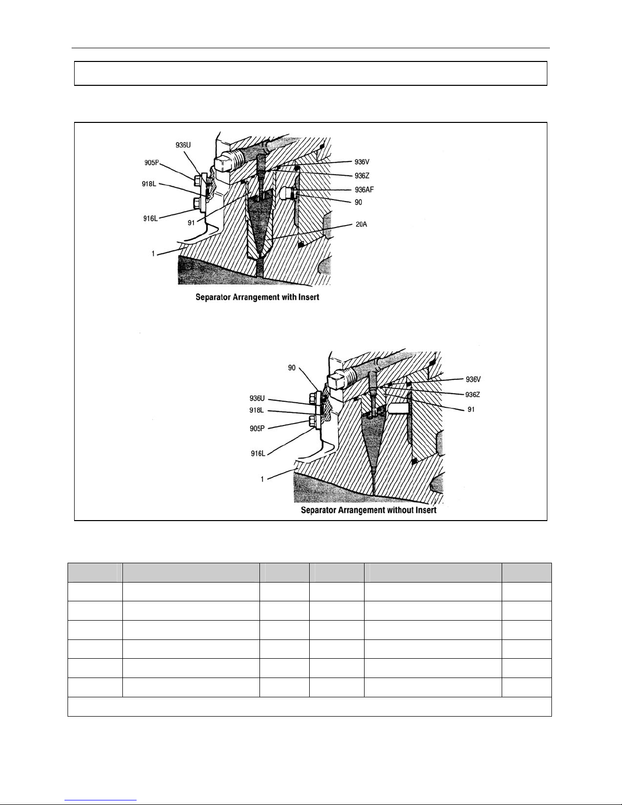
Integral Centrifugal Separator
Figure 13. Integral Centrifugal Separator
Item No. Part Name Qty. Item No. Part Name Qty.
1 Pump Casing 1 918L Pin 1
20A Separator Insert 1 936U O-ring Packing *1
90 Separator Orifice 1 936V O-ring Packing *1
91 Separator Fitting 1 936Z O-ring Packing *1
905P Hex Head Ca p Screw 2 936AF O-ring Packing *1
916L Washer 2
*Recommended Spare Parts
Table 10. Integral Centrifugal Separator Parts List
35

Instruction and Operation Manual
Extended Motor Shaft Adapter
Figure 14. Extended Motor Shaft Adapter
101
914B
916S
102
87A
916S
905A
Table 11. Extended Motor Shaft Adapter Parts List
Item No. Part Name Qty.
101 Adapter, Extended Motor Shaft 1
102 Shims As required
87A Thermal Barrier Gasket 1
905A Hex He ad Cap Screw 4
916S Washer, lock 3/8” 4
916S Washer, flat 3/8” 4
914B Nut, hex 3/8”-16 4
36

Instruction and Operation Manual
Recommended Spare Parts List
Table 12. Recommended Spare Parts List
ITEM NO. PAGE NO.
4
3 (or 10)
87A
115A
RKORP801
936A
936D
936E
936F
936G
936H
936J
936V
936Z
5
21B
50
51A
60A
936H
936J
DESCRIPTION
PUMP
Impeller Key
Impeller Bolt (or Inducer Stud)
Thermal Barrier Gasket
Lip Seal
O-ring Repair kit (Includes following)
- O-ring Packing
- O-ring Packing
- O-ring Packing
- O-ring Packing
- O-ring Packing
- O-ring Packing
- O-ring Packing
- O-ring Packing
- O-ring Packing
- Impeller Tab Washer
SINGLE SEAL
Throttle Bushing
Slinger Sleeve
Seal Rotating Face
Mechanical Seal
O-ring
O-ring
CLASS
1 2 3
QTY QTY QTY
1
1
1
1
1
1
2
2
1
2
2
1
2
2
1
1
1
1
2
1
1
2
1
1
8
8
4
2
2
1
50A
50B
51C
60A
60B
936H
936J
50A
50B
51A
60A
60B
60B
51C
936H
936J
DOUBLE SEAL
Shaft Sleeve (Lower)
Shaft Sleeve (Upper)
Seal Rotating Face
Mechanical Seal (Lower)
Mechanical Seal (Upper)
O-ring
O-ring
TANDEM SEALS
Shaft Sleeve (Lower)
Shaft Sleeve (Upper)
Seal Rotating Face
Mechanical Seal (Lower)
Mechanical Seal (Upper)
Mechanical Seal (Upper Gas)
Seal Rotating Face
O-ring
O-ring
37
1
1
1
1
2
1
1
2
1
1
2
1
1
8
8
4
4
4
2
1
1
1
1
2
1
1
2
1
1
2
1
1
2
1
1
2
1
1
8
8
4
6
6
3

Instruction and Operation Manual
Notes: Seal repair kits for standard seals are
available. O-rings for standard units are
available as a packaged o-ring Kit. The
o-ring repair kit does not include o-rings
936B and 936C.
Class 1: Minimum recommended spare
parts necessary to perform a
startup, and inspection of a new
unit.
Class 2: Minimum recommended spare
parts necessary to cover 1-2
years of normal operation.
Class 3: Minimum recommended spare
parts stock necessary for critical
services or units that will be
installed in remote locations.
38

Instruction and Operation Manual
Figure 15. Pump Exploded View
39

Instruction and Operation Manual
INDEX
Auxiliaries, 3
Chemical Use, 3
Common Parts List, 25
Control Checklist, 4
Controlling the Pump During Startup, 9
Diffuser Cone Extension, 33
Disassembling the LMV-801, 12
Double Seal Arrangement and Parts, 28
Driver Instructions, 3
Driver Rotation, 4
Driver Shaft Position Figure, 15
Electrical Safety, 2
Entrained Gases, 10
Environmental Control System, 4
Equipment and Safety Precautions, 2
Extended Motor Shaft, 1
Extended Motor Shaft - Shoulder Dimension, 15
Extended Motor Shaft Adapter, 35
Fall Protection, 3
Inducer & Parts, 32
Inspection, 6
Inspection, Cleaning, & Shimming the Extended
Motor Shaft, 15
INSTALLATION, 6
Installation and Start-Up Checklist, 5
Integral Centrifugal Separator, 34
ISO 9001, 2
Liquid Buffer System, 8
Machine Familiarization, 3
MAINTENANCE, 12
Mechanical Seal, 16
Minimum Flow Conditions, 10
Operating Conditions, 4
OPERATION & CONTROL, 10
Operation of Sundyne Pumps, 10
Parallel Operation, 9, 11
Parallel Operation Figure, 11
Parallel Units Common Valve Figure, 11
Personal Protective Equipment, 2
Piping Connections, 4
Pre-Commission Checklist, 3
Pressurizing Fluid Loop, 4
Preventative Machine Guards, 3
Pump Diagnostics, 21
Pump Exploded View Figure, 38
Pump Mechanical Seal Diagnostics, 23
Reassembling the LMV-801, 17
Recommended Spare Parts List, 36
Seal Environmental Control System, 7
Seal Housing Port Identification Figure, 8
Service Check Points Figure, 20
Setting the Valves, 4
Shaft and Lip Seal, 15
Shaft Sleeve, 16
Shoulder Dimension Figure, 15
Single Operation, 9
Single Seal Arrangement and Parts, 26
SPECIFICATIONS, 24
START UP, 9
Start Up Checklist, 4
Start-Up Procedures, 9
Storing Your Pump Long-Term, 6
Storing Your Pump Short-Term, 6
Suction and Discharge Piping, 7
Suction Conditions, 10
Sundyne Centrifugal Pumps, 1
System Head Curve, 10
Tandem Seal Arrangement and Parts, 30
Testing Equipment, 2
Text Symbols, 1
Torque Values, 24
TROUBLESHOOTING, 21
Typical Operation Figure, 10
Using Forklifts, 2
40

14845 W. 64th Avenue • Arvada, Colorado 80007 USA • +1-303-425-0800 • FAX: +1-303-425-0896 • www.sundyne.com
Sundyne Europe • Dijon (Longvic) • France • +33 (0) 3.80.38.33.00 • FAX: +33 (0)3.80.38.33.66
Sundyne Nikkiso • 27-10, Ebisu 2-Chome, Shibuya-Ku • Tokyo 150-0013, Japan • +81-3-3444-6475 • FAX: +81-3-3444-6806
ANSIMAG • ANYSPEED • CASTER • GSP • HMD/KONTRO • MASO/SINE • SUNDYNE COMPRESSORS • SUNDYNE • SUNFLO
 Loading...