

Page 1

Solar Pool Heating Systems
Installation Manual
Page 2

Table of Content
1 Introduction . . . . . . . . . . . . . . . . . . . . . . . . . . . . . . . . . . . . . . . . . . . . . . . . . . . . . . . . . . . . . . . . . . . . . . . . . . . . . . . . . . . . . . . . . . . . . . . . . . . . . . . . . . . . . . . . . . . . . 3
2 Getting Started . . . . . . . . . . . . . . . . . . . . . . . . . . . . . . . . . . . . . . . . . . . . . . . . . . . . . . . . . . . . . . . . . . . . . . . . . . . . . . . . . . . . . . . . . . . . . . . . . . . . . . . . . . . . . . . . . . 3
3 Pipe and Pipe Fittings . . . . . . . . . . . . . . . . . . . . . . . . . . . . . . . . . . . . . . . . . . . . . . . . . . . . . . . . . . . . . . . . . . . . . . . . . . . . . . . . . . . . . . . . . . . . . . . . . . . . . . . . . . . 4
4 Cleaner and Cement . . . . . . . . . . . . . . . . . . . . . . . . . . . . . . . . . . . . . . . . . . . . . . . . . . . . . . . . . . . . . . . . . . . . . . . . . . . . . . . . . . . . . . . . . . . . . . . . . . . . . . . . . . . . 4
5 Panels and Installation Kits . . . . . . . . . . . . . . . . . . . . . . . . . . . . . . . . . . . . . . . . . . . . . . . . . . . . . . . . . . . . . . . . . . . . . . . . . . . . . . . . . . . . . . . . . . . . . . . . . . . . . 4
6 Solar Collector Layout. . . . . . . . . . . . . . . . . . . . . . . . . . . . . . . . . . . . . . . . . . . . . . . . . . . . . . . . . . . . . . . . . . . . . . . . . . . . . . . . . . . . . . . . . . . . . . . . . . . . . . . . . . . 6
7 Solar Pool Heating Systems Components. . . . . . . . . . . . . . . . . . . . . . . . . . . . . . . . . . . . . . . . . . . . . . . . . . . . . . . . . . . . . . . . . . . . . . . . . . . . . . . . . . . . . 7
8 Installation . . . . . . . . . . . . . . . . . . . . . . . . . . . . . . . . . . . . . . . . . . . . . . . . . . . . . . . . . . . . . . . . . . . . . . . . . . . . . . . . . . . . . . . . . . . . . . . . . . . . . . . . . . . . . . . . . . . . . . . 9
8.1 Before You Start . . . . . . . . . . . . . . . . . . . . . . . . . . . . . . . . . . . . . . . . . . . . . . . . . . . . . . . . . . . . . . . . . . . . . . . . . . . . . . . . . . . . . . . . . . . . . . . . . . . . . . . . . . . . . . . . . . . . . . . . . . . . . . . . . . . . . . . . 9
8.2 Array Size . . . . . . . . . . . . . . . . . . . . . . . . . . . . . . . . . . . . . . . . . . . . . . . . . . . . . . . . . . . . . . . . . . . . . . . . . . . . . . . . . . . . . . . . . . . . . . . . . . . . . . . . . . . . . . . . . . . . . . . . . . . . . . . . . . . . . . . . . . . . . . . . 9
8.3 Space Required For Array . . . . . . . . . . . . . . . . . . . . . . . . . . . . . . . . . . . . . . . . . . . . . . . . . . . . . . . . . . . . . . . . . . . . . . . . . . . . . . . . . . . . . . . . . . . . . . . . . . . . . . . . . . . . . . . . . . . . . . . . .9
8.4 Flow Rate through Array . . . . . . . . . . . . . . . . . . . . . . . . . . . . . . . . . . . . . . . . . . . . . . . . . . . . . . . . . . . . . . . . . . . . . . . . . . . . . . . . . . . . . . . . . . . . . . . . . . . . . . . . . . . . . . . . . . . . . . . . 10
8.5 Control Module Location. . . . . . . . . . . . . . . . . . . . . . . . . . . . . . . . . . . . . . . . . . . . . . . . . . . . . . . . . . . . . . . . . . . . . . . . . . . . . . . . . . . . . . . . . . . . . . . . . . . . . . . . . . . . . . . . . . . . . . . . 10
8.6 Pipe Size . . . . . . . . . . . . . . . . . . . . . . . . . . . . . . . . . . . . . . . . . . . . . . . . . . . . . . . . . . . . . . . . . . . . . . . . . . . . . . . . . . . . . . . . . . . . . . . . . . . . . . . . . . . . . . . . . . . . . . . . . . . . . . . . . . . . . . . . . . . . . . . .10
8.7 Piping Arrangement . . . . . . . . . . . . . . . . . . . . . . . . . . . . . . . . . . . . . . . . . . . . . . . . . . . . . . . . . . . . . . . . . . . . . . . . . . . . . . . . . . . . . . . . . . . . . . . . . . . . . . . . . . . . . . . . . . . . . . . . . . . . . 10
8.8 Layout of the Solar Panel Array . . . . . . . . . . . . . . . . . . . . . . . . . . . . . . . . . . . . . . . . . . . . . . . . . . . . . . . . . . . . . . . . . . . . . . . . . . . . . . . . . . . . . . . . . . . . . . . . . . . . . . . . . . . . . . . . . 11
8.9 Solar Panels.. . . . . . . . . . . . . . . . . . . . . . . . . . . . . . . . . . . . . . . . . . . . . . . . . . . . . . . . . . . . . . . . . . . . . . . . . . . . . . . . . . . . . . . . . . . . . . . . . . . . . . . . . . . . . . . . . . . . . . . . . . . . . . . . . . . . . . . . . . . . 12
8.10 Assemble the Solar Panel Array . . . . . . . . . . . . . . . . . . . . . . . . . . . . . . . . . . . . . . . . . . . . . . . . . . . . . . . . . . . . . . . . . . . . . . . . . . . . . . . . . . . . . . . . . . . . . . . . . . . . . . . . . . . . . . . .12
8.11 Mounting the Solar Panel Array . . . . . . . . . . . . . . . . . . . . . . . . . . . . . . . . . . . . . . . . . . . . . . . . . . . . . . . . . . . . . . . . . . . . . . . . . . . . . . . . . . . . . . . . . . . . . . . . . . . . . . . . . . . . . . . . 14
8.12 Flat Roofs . . . . . . . . . . . . . . . . . . . . . . . . . . . . . . . . . . . . . . . . . . . . . . . . . . . . . . . . . . . . . . . . . . . . . . . . . . . . . . . . . . . . . . . . . . . . . . . . . . . . . . . . . . . . . . . . . . . . . . . . . . . . . . . . . . . . . . . . . . . . . . .15
8.13 Ground Mounting Rack . . . . . . . . . . . . . . . . . . . . . . . . . . . . . . . . . . . . . . . . . . . . . . . . . . . . . . . . . . . . . . . . . . . . . . . . . . . . . . . . . . . . . . . . . . . . . . . . . . . . . . . . . . . . . . . . . . . . . . . . . 18
8.14 Plumbing the System. . . . . . . . . . . . . . . . . . . . . . . . . . . . . . . . . . . . . . . . . . . . . . . . . . . . . . . . . . . . . . . . . . . . . . . . . . . . . . . . . . . . . . . . . . . . . . . . . . . . . . . . . . . . . . . . . . . . . . . . . . . . 19
8.15 Plumbing Connections. . . . . . . . . . . . . . . . . . . . . . . . . . . . . . . . . . . . . . . . . . . . . . . . . . . . . . . . . . . . . . . . . . . . . . . . . . . . . . . . . . . . . . . . . . . . . . . . . . . . . . . . . . . . . . . . . . . . . . . . . . 20
9 Installation Procedure . . . . . . . . . . . . . . . . . . . . . . . . . . . . . . . . . . . . . . . . . . . . . . . . . . . . . . . . . . . . . . . . . . . . . . . . . . . . . . . . . . . . . . . . . . . . . . . . . . . . . . . . 20
10 Pipe Layout. . . . . . . . . . . . . . . . . . . . . . . . . . . . . . . . . . . . . . . . . . . . . . . . . . . . . . . . . . . . . . . . . . . . . . . . . . . . . . . . . . . . . . . . . . . . . . . . . . . . . . . . . . . . . . . . . . . . . . . . 24
11 Pipe Layout. . . . . . . . . . . . . . . . . . . . . . . . . . . . . . . . . . . . . . . . . . . . . . . . . . . . . . . . . . . . . . . . . . . . . . . . . . . . . . . . . . . . . . . . . . . . . . . . . . . . . . . . . . . . . . . . . . . . . . . . 25
12 Control installation . . . . . . . . . . . . . . . . . . . . . . . . . . . . . . . . . . . . . . . . . . . . . . . . . . . . . . . . . . . . . . . . . . . . . . . . . . . . . . . . . . .25
12.1 Solar Controls . . . . . . . . . . . . . . . . . . . . . . . . . . . . . . . . . . . . . . . . . . . . . . . . . . . . . . . . . . . . . . . . . . . . . . . . . . . . . . . . . . . . . . . . . . 25
12.2 TypicalAutomatic Control System . . . . . . . . . . . . . . . . . . . . . . . . . . . . . . . . . . . . . . . . . . . . . . . . . . . . . . . . . . . . . . . . . . . . . . . 26
12.3 System Check Start-Up . . . . . . . . . . . . . . . . . . . . . . . . . . . . . . . . . . . . . . . . . . . . . . . . . . . . . . . . . . . . . . . . . . . . . . . . . . . . . . . . . 27
12.4 TypicalAutomatic Control Components . . . . . . . . . . . . . . . . . . . . . . . . . . . . . . . . . . . . . . . . . . . . . . . . . . . . . . . . . . . . . . . . 27
12.5 Typical Control Operating (Les fonctions du ControleAutomatique) . . . . . . . . . . . . . . . . . . . . . . . . . . . . . . . . . . . . . 27
13 Special Roof Requirements . . . . . . . . . . . . . . . . . . . . . . . . . . . . . . . . . . . . . . . . . . . . . . . . . . . . . . . . . . . . . . . . . . . . . . . . . . 28
14 Operating and Check-Out Procedures . . . . . . . . . . . . . . . . . . . . . . . . . . . . . . . . . . . . . . . . . . . . . . . . . . . . . . . . . . . . . . . .29
15 Troubleshooting Guide. . . . . . . . . . . . . . . . . . . . . . . . . . . . . . . . . . . . . . . . . . . . . . . . . . . . . . . . . . . . . . . . . . . . . . . . . . . . . . . 30
Solar Pool System
Installation Manual
2
Page 3

1. Introduction
Before attempting installation, read the instructions in this manual carefully. This manual contains
easy to follow step-by-step procedures to property install our Techno-Solis pool solar system. Your
understanding our system and it parts will assure a successful, trouble-free installation. If you have
any product or installation questions regarding this installation, contact our representative at your
nearest area.
It is important to recognize that this manual outlines the recommended installation methods and
practices as prescribed by the factory. It is designed to aid the installer or even the novice through
providing optimum protection for the products. Also, these are the minimal requirements; additional protection may be required in hazardous environments or in areas subject to extremes of weather.
In those areas, the local expertise of the contractor may be relied upon in coordination with our approval for special installation considerations.
Take time to read through this manual. It will guide you through the most e cient way to correctly
install our pool solar system. By following this step by step guide, your system will meet the installation standards recommended by the factory. In addition, because we’ve included techniques and
tips gathered from experienced SUNDWARE contractors throughout the countries, using this installation will save you time and e ort.
2. Getting Started
Before you begin your installation, here are a few important advices:
1. Caution- Safety Comes First !!!!
• There is no substitute for safety. Always exercise extreme caution, care and good jud
ments when working on or around a roof or pool area.
• Please take care to avoid hazards such as over-head electrical wires or loose shingles or
roof tiles.
• Be sure to secure ladders so they will not slip or fall.
• Do not allow extension cords to lie in the pool or in standing water.
• Wear shoes with proper tread to prevent slipping on the ladder or sloped roof areas.
• Disconnect all power to the pool equipment when installing an automatic control
system.
2. Before starting any work, determine the location of your system and prepare a schematic
drawing of the installation area. Include the location of the feed and return lines in this
drawing. Roof areas often times look bigger than they really are, so be sure to measure the
available area before making your schematic.
3
Solar Pool System
Installation Manual
Page 4

3. The planned placement of the panels should allow the panels to drain when the pool pump
shuts o .
4. The paint of the outdoor pipes and ttings should be UV resistant. Painted pipes and ttings
will require additional maintenance.
5. Never walk on collectors when they are wet as they present a signi cant slip hazard. Walking
on the collectors should only take place when absolutely necessary.
6. Familiarize yourself with all of our pool solar components and plumbing materials that are
needed to complete the installation.
3. Pipe and Pipe Fittings
Use pressure rated Schedule 40 PVC pipe. You may prefer to use black, but because black PVC
can be di cult to nd, some installers have inquired about the use of black ABS pipe instead. DO
NOT USE ABS PIPE. ABS pipe does not have the UV inhibitors that PVC pipe has, causing ABS pipe
to become brittle and to crack after several years of exposure.
Use PVC Schedule 40 pressure-rated fi ttings to match your PVC pipe. Be sure NOT TO USE
“plumbers” fi ttings or DWV fi ttings (drain, waste and vent).
4. Cleaner and Cement
Refer to the product’s label for selecting good quality Cleaner and CPVC all-purpose cement.
Before applying the cement, be sure to clean each fi tting and pipe end with the PVC Cleaner
or “primer.” Soon after cleaning each part, apply ample cement fi rst to the fi tting and then to the
pipe end. Insert the pipe end into the fi tting with a slight twisting motion until it seats to evenly
distribute the glue. Hold it in this position for 5 to 10 seconds to allow the joint to set up. Finally,
wipe excess cement off of the joint and pipe.
Note: Cold weather slows the set-up process for PVCglue. If installing in colder climates, refer to the
PVC glue manufacturer’s charts for curing times.
5. Panels and Installation Kits
Planning ahead and having the proper partsand kits for your system will make your installation
much easier. The kits and parts that are useful for our systems are shown here below under the
title “PARTS LIST ”.
Solar Pool System
Installation Manual
4
Page 5

1. Necessary items:
A) SOLAR PANELS :
C15TS12 SOLAR PANEL 4’ x 12’
or C15TS10 SOLAR PANEL 4’ x 10’
or C15TS08 SOLAR PANEL 4’ x 8’
B) KITS :
K15 SYSSYSTEM KIT
(one per system) includes :
2 A15ADAPipe to panel adap. PVC 1 ½”x3” lg.
5 ALAGScrew ¼” x 2” lg. and washer
1 ARS-SILCaulking silicone
1 F20BSTRAP2”- black steel “U” support
2 K15BCAPEnd cap kit 1 ½”
K15 PANPANEL KIT
(one per system) includes :
2 A15HOSEPDM hose 1 ½”
4 AGC32Gear clamp #32
5 ALAGScrew ¼” x 2” lg. and washer
1 F20BSTRAP2”- black steel “U” support
½ ASTR29PPolyester strap roll (29 pi.)
K15PBWPIPING KIT PVC 1 1/2”
(one per system) includes :
1 AGC32Gear clamp #32
1 AGLUE1/2PT PVC glue #711
24 ALAGScrew ¼” x 2” lg. and washer
6 F15B901 1/2” PVC black 90° elbow
2 F15BCOU1 1/2” PVC black straight coupling
4 F15BSTRAP1 1/2” black steel “U” support
1 F15CORL/S1 1/2” PVC adaptor corlon/slip
10 F15W901 1/2” PVC white 90° elbow
1 F15WADA-M 1 1/2” PVC white male adapt.
4 F15WCOU1 1/2” PVC white straight coupling
8 F15WSTRAP 1 1/2” white steel “U” support
1 F15WTEE1 1/2” PVC white tee
40 P15B(ft.) 1 1/2” PVC black pipe
60 P15W(ft.) 1 1/2” PVC white pipe
C) CONTROLS
K15CTRMMANUAL CONTROL KIT
(one per system) includes :
1F15V21 1/2” PVC ball valve
1F15VCHECK 1 1/2” PVC check valve
1F15WTEE1 1/2” PVC white tee
1F15WU1 1/2” PVC white union
or
K15CTRAAUTO. CONTROL KIT
(one per system) includes :
4C-3MWire nuts
1C-FV2.03 way motorized valve PVC 2”
1C-HM4000HM4000 control box
1C-PSPool sensor #1S 1.0-10K
1C-RSRoof sensor #AS2-10K
10 C-TYETy-wrap 11” lg.
100 C-WIRE(ft.) Shielded wire #2-18
1F15VCHECK 1 1/2” PVC check valve
1F15WU1 1/2” PVC white union
3F20WRED152”x1 1/2” PVC red. bushing
2. Optional items :
K15BKBBANK KIT 1 1/2”
includes :
2A15ADAPipe to panel adap. PVC 1 ½”x3” lg.
5ALAGScrew ¼” x 2” lg. and washer
2F15B901 1/2” PVC black 90° elbow
1F20BSTRAP2”- black steel “U” support
2K15BCAPEnd cap kit 1 ½”
K15SPLBSPLIT KIT 1 1/2”
includes :
4A15ADAPipe to panel adap. PVC 1 ½”x3” lg.
2A15HOSEPDM hose 1 ½”
4AGC32Gear clamp #32
5ALAGScrew ¼” x 2” lg. and washer
4F15BCOU1 1/2” PVC black straight coupling
1F20BSTRAP2”- black steel “U” support
K15UNGUNDERGROUND KIT
includes :
4 AGC32Gear clamp #32
4 F15CORL/90C 1 1/2” PVC 90° elbow corlon/glued
4 F15CO1 1/2” DVW clean-out
4 F15WTEE1 1/2” PVC white tee
PARTS LIST
5
Solar Pool System
Installation Manual
Page 6
6. Solar Collector Layout
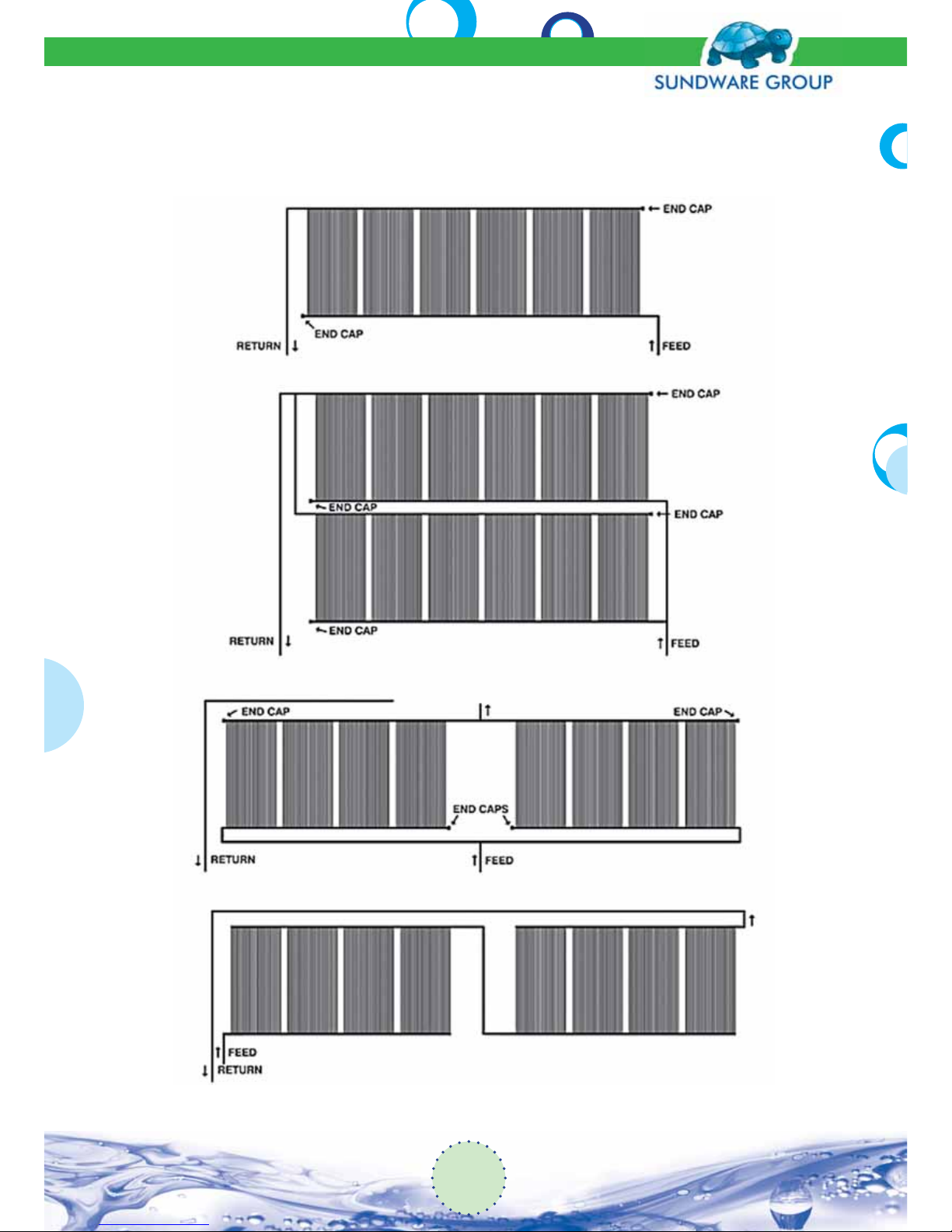
The most common solar collector installations are shown below:
Note: No more than two (2) arrays are allowed in series feed and no more than eight (8) collectors are allowed in each array.
Fig (1): Single Row
Fig (2): Double Row
Fig (3): Single Row Spit Feed
Fig (4): Series Feed
Solar Pool System
Installation Manual
6
Page 7
7. Solar Pool Heating Systems Components
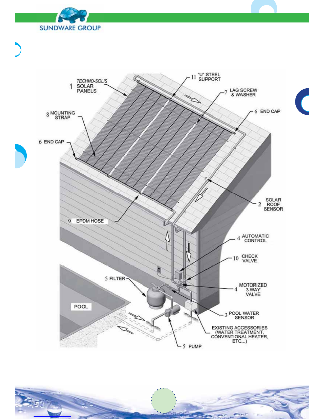
Fig (5): Techno-Solis Solar Pool Heating System Components
7
Solar Pool System
Installation Manual
Page 8

The Solar pool system has the following components (see gure 5)
1. The SUNDWARE PANELS are the key to your system. They absorb the sun’s heat e ciently
and transfer the energy to the swimming pool water that is pumped through them.
2. The SOLAR ROOF SENSOR* is installed beside the SUNDWARE solar panels to sense the
heat from the Sun. It relays the solar panel temperature to the automatic control.
3. The POOL WATER SENSOR* is installed in the pool plumbing, after the lter. It senses the
pool water temperature and relays the information to the automatic control.
4. The AUTOMATIC CONTROL and MOTORIZED 3-WAY VALVE* compare the pool water tem-
perature to the solar roof temperature to turn the SUNDWARE solar heating system on or
o , as required.
5. The existing PUMP and FILTER circulate clean water to the pool and through the solar
panels when required.
6. The END CAPS seal the solar panel headers at the end of the row.
7. The LAG SCREWS and WASHERS are used to secure mounting straps to the roof.
8. The MOUNTING STRAPS are used with lag screw and washer to secure the solar panels to
the roof.
9. The EPDM HOSES connect the SUNDWARE solar panels together and connect the piping
to the solar panel array.
10. The CHECK VALVE* is used to prevent back ow circulation in the solar panels at night.
(1/8” diameter hole to be drilled in the apper to allow for winter drainage).
11. The “U”STEEL SUPPORTS are used to anchor the top header of the solar panels.
* Only used in systems with automatic control.
Some systems will use a manual valve for turning the system on or o .
Solar Pool System
Installation Manual
8
Page 9
8. Installation
8.1 Before You Start
Please read the complete manual before starting. If you have any installation problems or questions, consult SUNDWARE GROUP’ distributor. Remember, serious damage may result from malfunction of the system and its components if instructions are not closely followed.
Check local plumbing, electrical and building codes. The installation must comply withthe local
regulations, which vary substantially from location to location.
8.2 Array Size
The number of solar panels required in the array is primary dependent upon the surface area of
the pool and the amount of solar energy available in the area of the installation.
The relationship between solar panel area and pool area should be: (for summer heating).
50% if solar panels are SOUTH facing
75% if solar panels are WEST facing
80% if solar panels are EAST facing
75% if solar panels are laid at (with a minimum of 10 degrees inclination for properdrainage)
8.3 Space Required For Array
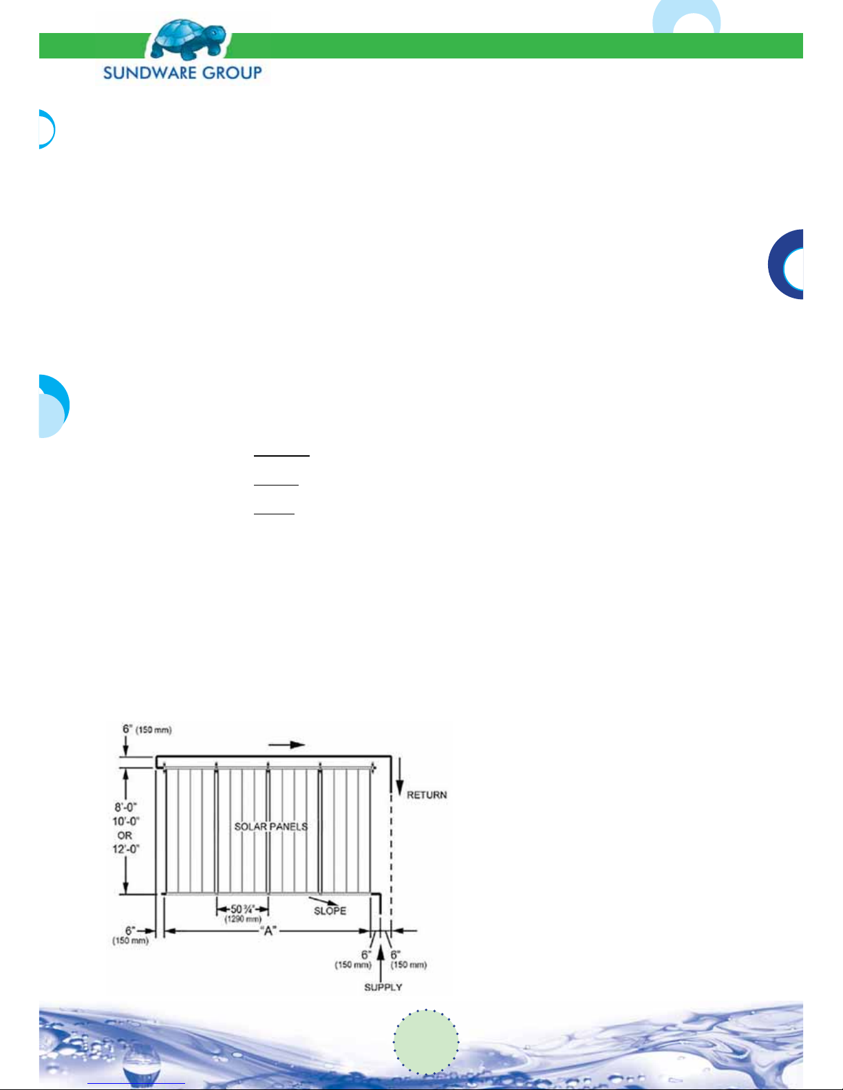
The minimum linear space for an array can be determined by the chart shown in gure (6). Add
any length required to bypass roof obstructions.
The minimum vertical space required is equal to the length of the solar panel (8’, 10’ or 12’) plus
6” (150 mm) for the feed and return pipe runs above or below the array. Add a slope of 1 inch in
10 ft. (25mm per 3 meters) for the feed and return pipe runs to permit drainage.
Fig (6): Space Required for Solar Panel Arrays
9
Solar Pool System
Installation Manual
Page 10
Quantity of Panels
“A”
in. m
3 12’-9” 3,89
4 17’-0” 5,18
5 21’-3” 6,5
6 25’-5” 7,77
7 29’-9” 9,06
8 34’-0” 10,36
9 38’-3” 11,65
10 42’-6” 12,95
11 46’-9” 14,24
12 51’-0” 15,54
8.4 Flow Rate through Array
The recommended ow rate through the array is 3 to 10 GPM (11 to 35 liters) per panel. A ow
rate of 5 GPM (18 liters) is recommended. The actual ow rate is not that shown on the pool
pump because of pressure losses in the system. The actual ow rate may be determined by using
an in-line ow meter or calculated the time it takes to ll a bucket of known capacity.
8.5 Control Module Location
Determine the location of the electronic control based on access to power, ease of cutting into
existing piping at the lter outlet, and piping to and from the array. (Refer to the control manufacturer’s instructions).
8.6 Pipe Size
Determine the length and size of the pipe required. Use only PVC pipe. Black ABS piping degrades when exposed to sunlight. Use pipe cleaner before gluing with PVC glue. If connecting to
ABS piping, use PVC glue, not yellow ABS glue. Allow several hours for glue to set before turning
on pump.
For runs of less than 80 ft (25 meters), either feed or return, use 1 ½” pipe. For runs of more than
80 ft. (25 meters) a 2” pipe is recommended. Pipe runs should be planned so that the panels and
piping drain when the system is not active.
8.7 Piping Arrangement (Figure 7)
a. Always pipe the array reverse-return. End-feed end-return systems are not e cient.
b. If possible, install the return pipe at the top of the array; this will eliminate the air in the
system.
Solar Pool System
Installation Manual
10
Page 11
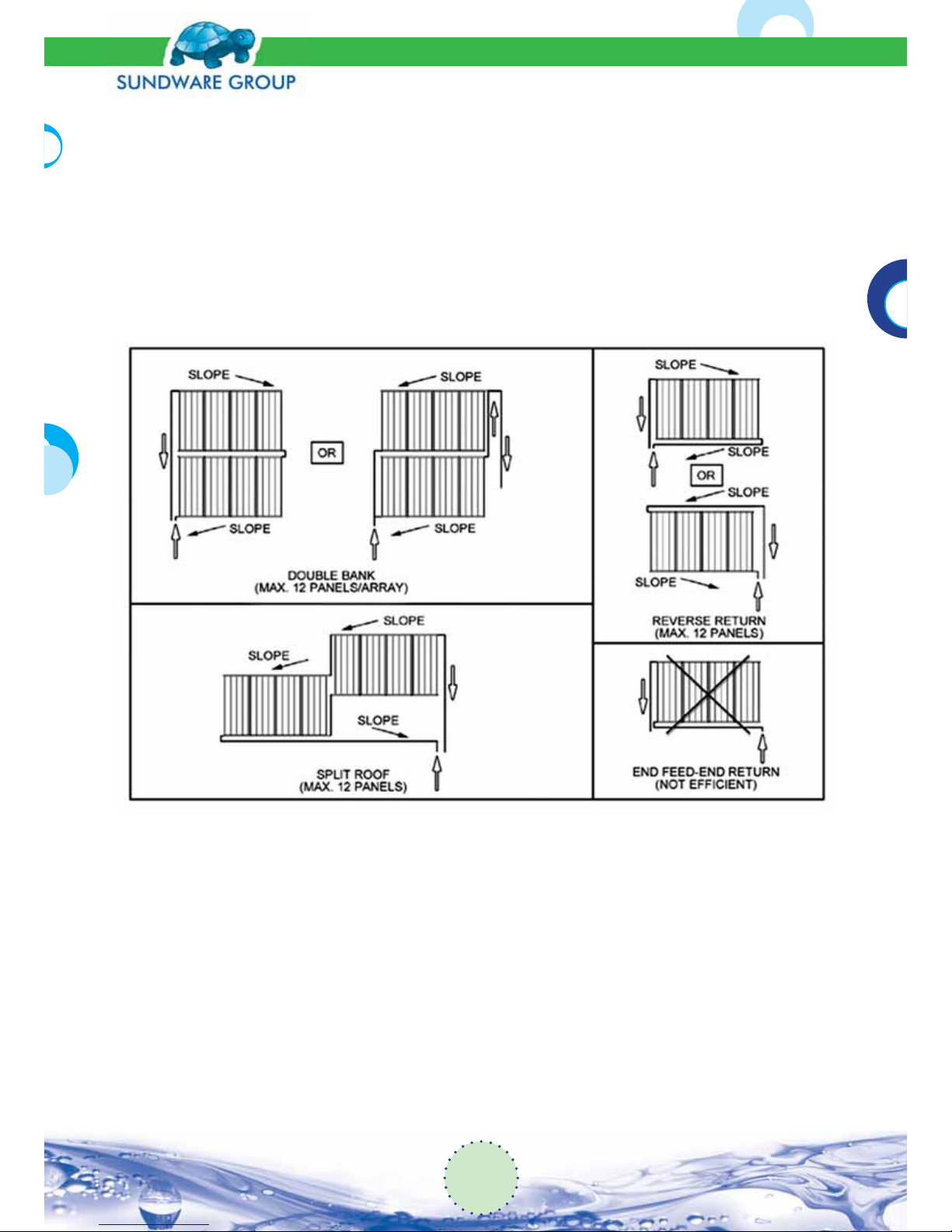
c. Feed at the lowest point in the system and connect the return line from all panels to the
highest point in the system.
d. All piping should be sloped continuously downward, towards the existing pump and lter.
If there are any low points or traps in the piping, drain plugs should be installed to ensure
complete drainage if the installation is an area subject to freezing conditions.
e. For multiple level, or split arrays, ensure that all return piping rises to a common high
point. Use abank kit (K15BKB) for multiple rows and a split kit (K15SPLB) for roof obstructions (see the part list of the pool systems in para 5).
Fig (7): Typical Panel and Piping Arrangements
8.8 Layout of the Solar Panel Array
a. Determine the exact location of the array, based on the required array con guration, the
existence of roof obstructions, proper feed and return pipe runs, shading of the panels and
any other speci c factors that may a ect the location of the array.
b. Utilizing a chalk line or string, make a horizontal line across as a reference for where the top
header of the panels will be located. Allow su cient room between the headers and the
roof line for pipe runs. Care must be taken to make the horizontal line truly horizontal. For
maximum protection against freezing, slope the entire array toward the feed pipe. The slope
should be 1” per 10’-0” (25 mm per 3 meters).
11
Solar Pool System
Installation Manual
Page 12
c. Carefully check the roof, where the array is to be mounted, for any sharp projection (nails,
screws, etc.) that may damage the solar panels.
d. If the array is to be on multiple levels, or split roofs, repeat steps 1 through 4 above for each
portion of the array. Ensure that all return piping rises to a common high point.
8.9 Solar Panels
The SUNDWARE solar panels are designed to resist expansion and contraction due to temperature variations. Even though the panels are made of resistant thermoplastic materials, care
should be taken when they are handled to avoid contact with sharp surfaces. When lifting the
panels onto the roof, take care not to damage them by dragging them over the edge of the roof.
8.10 Assemble the Solar Panel Array
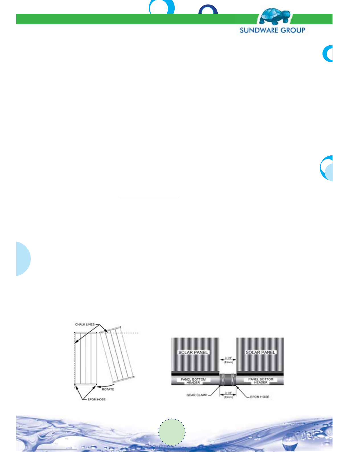
The headers of adjacent panels are joined to each other by an EPDM hose (item # 9), with two
stainless steel gear clamps. Do not over tighten these clamps as it may cause the end of the
header to collapse. Care must be taken to ensure that the stainless steel gear clamps are placed
to match the groove in the header.
1. On the ground, prior to lift the panels on the roof, place an EPDM hose on one end of the
headers of each panel. Do not tighten the gear clamps, unless required to do so because of
wind or roof slope (see gures 8 and 9).
a. Place the second panel beside the rst so that the top headers are approximately 2 to 3”
(5 to 7 mm) apart.
b. Snap the top header of the second panel into the EPDM hose of the rst panel.
c. Rotate the bottom of the second panel toward the rst panel, and then snap it into
postion.
d. Tighten all gear clamps.
e. Repeat assembly procedures until array is complete.
F ig (8): Panel Assembly Fig (9): EPDM Panel Hose
Solar Pool System
Installation Manual
12
Page 13
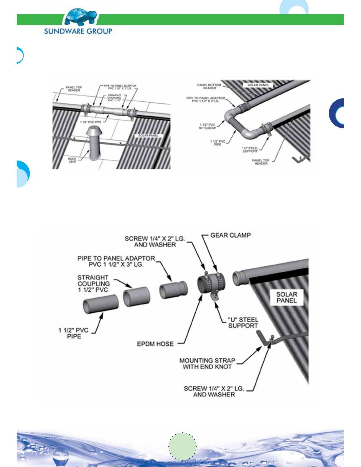
2. Roof obstructions (see gure 10) or split arrays (see gure 11) require that a PVC grooved
pipe to panel adaptor be inserted into the EPDM hoses. Each obstruction, or split, requires a
split kit (see the part list in para 5-Optional Items).
Fig (10): Split Kit Fig (11): Bank Kit
3. When an array has been assembled, it is ready to be secured to the roof. Adjust the array so
that the headers are sloped 1” per 10’-0” (25 mm per 3 meters) towards the feed line.
Fig (12): Split Kitor Last Panel Piping Details
13
Solar Pool System
Installation Manual
Page 14
4. The feed line will be connected to the lowest point in the array and an end cap (item #6) will
be installed at the other end of the array in the bottom header.
5. The return line will be connected at the highest point in the array, opposite of the feed line,
and an end cap (item #6) will be place in the other end of the top header of the array. Consult gure (7) for double bank arrays.
8.11 Mounting the Solar Panel Array
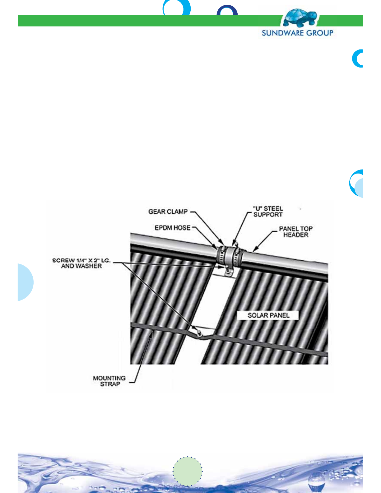
1. Starting at either end of the array, install a “U” steel support (item #11) over a top header
EPDM hose and anchor to the roof using two lag screws and washers (item #7). Make sure to
place a generous amount of caulking material on the roof at the point where the screws will
penetrate the surface (see gure 13).
2. Repeat this procedure across the array, securing a “U” steel support over each top header
EPDM hose. Only the top header of the array should be anchored in this manner.
Fig (13): Panel Mounting Details
3. For the installation of the rst mounting strap, locate a point on the roof approximately 12”
(300 mm) above thebottom header and 2” (50 mm) out from the edge panel. Tie a knot in
the end of the mounting strap (item #8), insert ina lag screw and washer, put caulking mate-
Solar Pool System
Installation Manual
14
Page 15
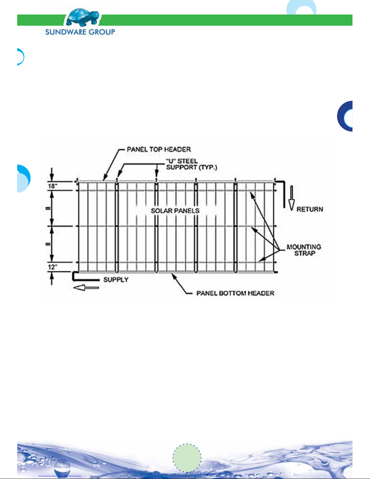
rial and anchor to the roof. Extend the mounting strap across the array to theopposite end.
At this point, pull the strap tight, tie a knot, put caulking and anchor it to the roof using a lag
screw andwasher, 12” (300 mm) up and 2” (50 mm) out from the edge of the last panel. Anchor mounting strap between eachpanels using lag screws and washers. Always use caulking when penetrating the roof.
4. Using the same procedure as in step 3, attach a second mounting strap at 18” (460 mm)
below the top header and athird one across the center of the array (see gure 14). For 12’-0”
panels, install across the array, a fourth mountingstrap equally spaced between the other
mounting straps.
Fig (14): Mounting Strap Arrangement
8.12 Flat Roofs
Flat roofs are more delicate to work on. Exercise extreme caution to prevent roof damage. Solar
panels can be mounted on at roofs if the length of the panels is sloped a minimum of 12” (300
mm) to ensure a good ow rate through the panels and to enable them to drain. A framework, illustrated in gure (15) made of 2” x 4” and 2” x 6” boards, will support the solar panels along their
length. All wood products must be pressure treated, exterior grade. This support should extend
a minimum of 6” (150 mm) around the panel array to support the feed and return pipe runs.
15
Solar Pool System
Installation Manual
Page 16
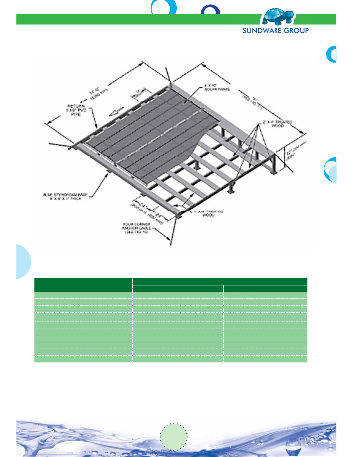
Quantity of Panels
“A”
in. m
3 14’-9” 4,5
4 19’-0” 5,8
5 23’-3” 7,1
6 27’-6” 8,4
7 31’-9” 9,7
8 36’-0” 11,0
9 40’-3” 12,2
10 44’-6” 13,6
11 48’-9” 14,9
12 53’-0” 16,2
Fig(15): Flat Roof Rack
Solar Pool System
Installation Manual
16
Page 17
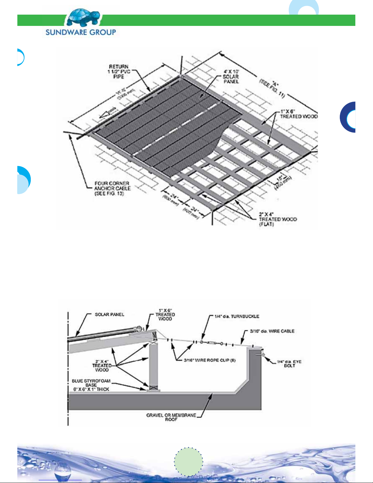
Fig (16): Low Pitched Roof
Installation on low pitched roof with asphalt shingles, gravel or membrane, requires also a framework of pressure treated wood (see gure 16). In both cases, the framework is attached to the
side of the house with a minimum of four steel cables (see gure 17). The waterproof membrane
of the roof is protected.
Fig (17): Roof Rack Attachment Details
17
Solar Pool System
Installation Manual
Page 18
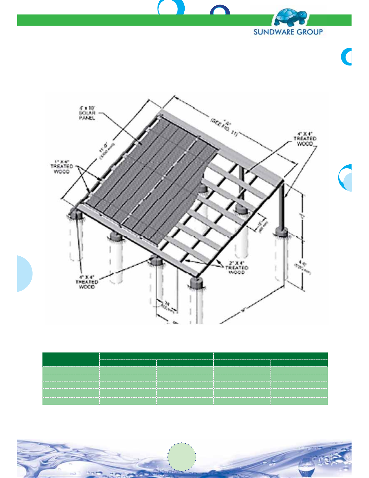
8.13 Ground Mounting Rack
This type of rack may be enclosed to serve as a shed for the pool lter. For di erent inclinations
see dimensions “B” and “C” in gure (18).
Degree
“B” “C”
ft m ft m
25 10’-1” 3,0 5’-0” 1,5
30 9’-6” 2,9 5’-6” 1,7
35 9’-0” 2,7 6’-6” 2,0
40 8’-6” 2,6 7’-6” 2,3
45 8’-0” 2,4 8’-0” 2,4
Fig (18): Ground Mount Rack
Solar Pool System
Installation Manual
18
Page 19
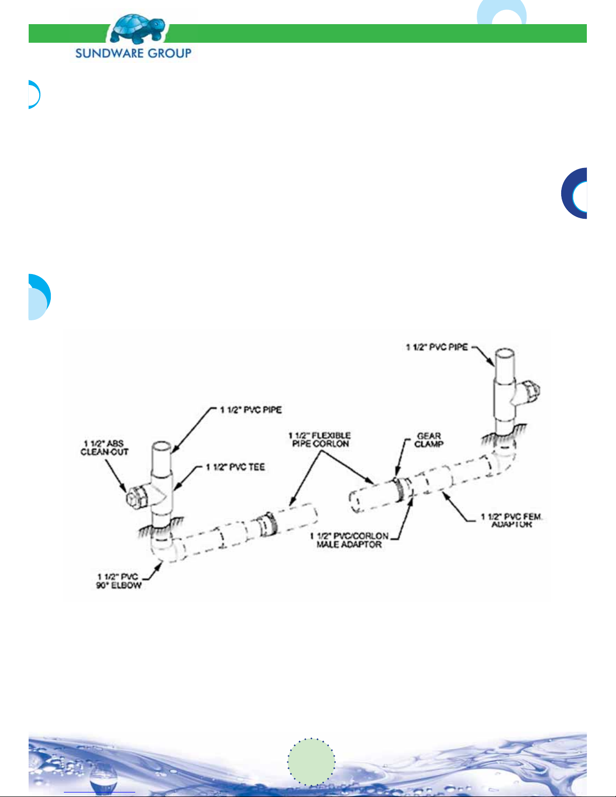
8.14 Plumbing the System
1. Feed and return connections to the array are made by inserting PVC grooved pipe to panel
adaptor into the panel EPDM hose and gluing the PVC pipe to the adaptor. Never attempt
to glue pipe directly to the solar panel header (see gure 12).
2. An end cap (item #6) must be plumbed into the array at the opposite end of the bottom
header to the feed line. If necessary, this end cap will totally drain the panels when the system is winterized. More end caps can be used in the plumbing to facilitate drainage.
3. Isolating valves (optional), plumbed in the array feed and return lines, near the electronic
control, are recommended so that the array can be isolated if desired.
4. With a pool ltration system far from the house, where the solar panels are installed, feed
and return lines are buried (see gure 19). Flexible corlon polyethylene piping is suggested
because it is more resistant to freezing. Rigid PVC pipe may freeze and break. Install drain
plugs at the both ends of the underground pipes using the underground kit K15UNG (see
para 5 –Parts List).
Fig (19): Underground Kit
5. Insulation is not needed since the pool water temperature and ambient air temperature are
almost the same. Winter conditions of snow and ice make it imperative that the system be
checked once a year by a quali ed installer: solar panel mounting straps, sensor wire, caulking, piping fastening and pipe drainage.
19
Solar Pool System
Installation Manual
Page 20

8.15 Plumbing Connections
1. Make a mock up with pipe ttings and the manual or automatic controller, to determine
the piping requirements. Follow the instructions supplied by the manufacturer of the
controller.
2. After determining size requirements, cut out the appropriate amount of existing piping.
3. Convert to PVC pipe with threaded adaptors. Always use Te on tape on threaded joints to
avoid leakage.
4. Feed and return piping should go around overhanging eaves to minimize risks of leaks.
9. Installation Procedure
The following procedure assumes a shingle roof:
Step (1): Establish a horizontal chalk line across the roof for the location of the top of the
system.
This line must have 3/4” clearance above and below it for mounting the Header Clip on a
flat surface. For tile roofs, the line should be approximately 2” above the bottom of the tile.
Note: For seasonal climates, this line must have a ¼” per foot slope towards the feed line
to allow for drainage and winterization. Then drop a vertical line (90° to the horizontal
line) at the left or right end of the installation to locate the first panel. Allow a minimum of
3” on all sides of the panel row for piping. Inspect the roof for any sharp projections that
may damage the panels.
Step (2): Lay out the system before securing any panels. Begin installing the panels on the
left working right towards the opposite end. The panels can be installed with either side
up, and should be flipped after five years to lengthen their life.
Step (3): Lay the top header approximately 1¼” below the horizontal chalk line. Using the
parts from the Panel Kit, install a 3” Rubber Coupling on the top right and bottom right
header outlet. Slide a Hose Clamp over each Rubber Coupling and position it over the
groove in the header. Rotate the head of each clamp facing up for easy access, shown in
Fig (20). Then tighten until snug.
Step (4): Slide another Hose Clamp over the top and bottom Rubber Coupling. Position
the next panel to the right of the first panel, and insert the header outlet into the top and
bottom Rubber Coupling of the first panel. Position each Hose Clamp over the groove of
the second panel; facing up for easy access. Then tighten until snug. The top and bottom
should resemble Fig (21) when finished. If the roof is not too steep for the panels to slide,
you may continue connecting panels following Step 3 then Step 4; otherwise move to
Step 5
Solar Pool System
Installation Manual
20
Page 21
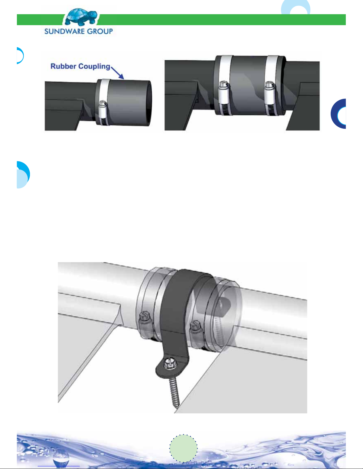
Step (5): Verify that the panels are in position (the top edge of the header should be parallel
to the horizontal line; the left edge of the very rst panel should be on the vertical line). Place
a U-Shaped Bracket over the upper Rubber Coupling and mark the roof where the Hex Screw
will penetrate. Remove the U-Shaped Bracket and apply a generous amount of sealant to the
marked areas on the roof. Return the U-Shaped Bracket. Using a drill and a 3/8” nut driver, drive
two Stainless 3/8 Hex Screws through the holes of the Bracket and into the roof.
Note (1): The U-Shaped Bracket should be tightly secured but be sure not to over tighten the
screws and strip the wood. When installed it should resemble Fig (22). Finally, apply sealant
around the head of the screws.
Note (2): The bottom headers are NOT secured with U- Shaped Brackets to allow for expansion.
Continue with Step 4 and Step 5 until all panels in the row are installed.
Fig (20): Rubber Coupling Fig (21): Rubber Coupling Installed
Fig (22): U-Shaped Bracket
21
Solar Pool System
Installation Manual
Page 22
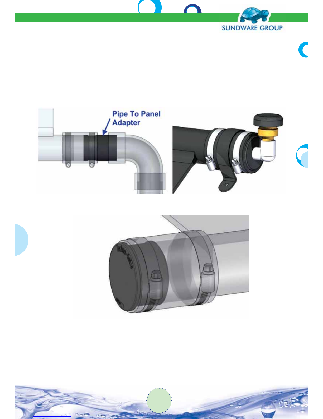
Step (6): Install a Rubber Coupling on the four outside remaining header corners using the Hose
Clamps. On the feed and return corners, insert the Pipe to Panel Adapters, seen in Fig (23), into
the Rubber Coupling using the end that resembles a header outlet. Secure with a Hose Clamp.
On the upper remaining corner, insert the vacuum breaker assembly, Fig (24), and secure with a
Hose Clamp. On the bottom remaining corner, insert an End Cap and secure with a Hose Clamp,
Fig (25). Secure the nal two top Rubber Couplings to the roof with U-Shaped Brackets just as you
did in Step 5.
Step (7): The Hold-Down Straps may now be installed- Fig (26). A minimum of 3 straps is
required In high wind areas increase the number of straps per panel row, particularly for
the longer panels.
Fig (23): Pipe to Panel Adapter Fig (24): Vacuum Breaker Assembly
Fig (25): End Cap
Solar Pool System
Installation Manual
22
Page 23
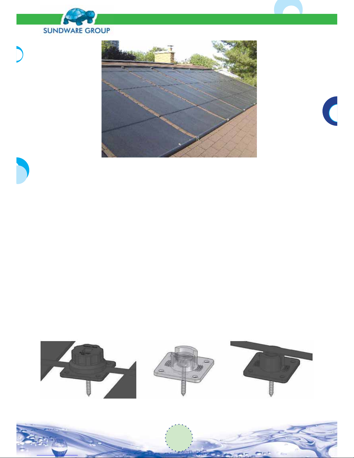
The bottom Strap is always located 12” above the bottom header. The remaining Strap(s) are
equally spaced between the bottom Strap and the top header. You may want to use a chalk line
to mark this spacing before you install the panels by measuring down from the top horizontal
line; or use the shingle lines as a guide.
Install SuperClips along the marked lines between all panels and at the ends of the row, Fig (27)
To install a SuperClip, apply a generous amount of sealant to the base of the clip. Place the base
on the marked line and secure with a Stainless 3/8 Hex Screw through the center hole of the
base, Fig (28).
The SuperClip base should be tightly secured but be sure NOT to over tighten the screw and
strip the wood. In high wind areas the base can be fastened in the four corners in addition to the
center.
Lay strap across the SuperClip base at the left end of the row. Screw on SuperClip cap rmly.
Stretch the strap across all the panels to the right and screw on the last SuperClip cap rmly while
the strap is under tension Fig (29). Now working from the center towards the ends of the row,
screw each cap on rmly.
After the system is installed for several weeks or even months the Strap may need to be re-tensioned due to expansion of the strap in warmer weather.
Fig (26): Hold straps
Fig (27): SuperClip Installed Fig (28): SuperClip Base Fig (23): Fig (29) Tensioned Strap
23
Solar Pool System
Installation Manual
Page 24
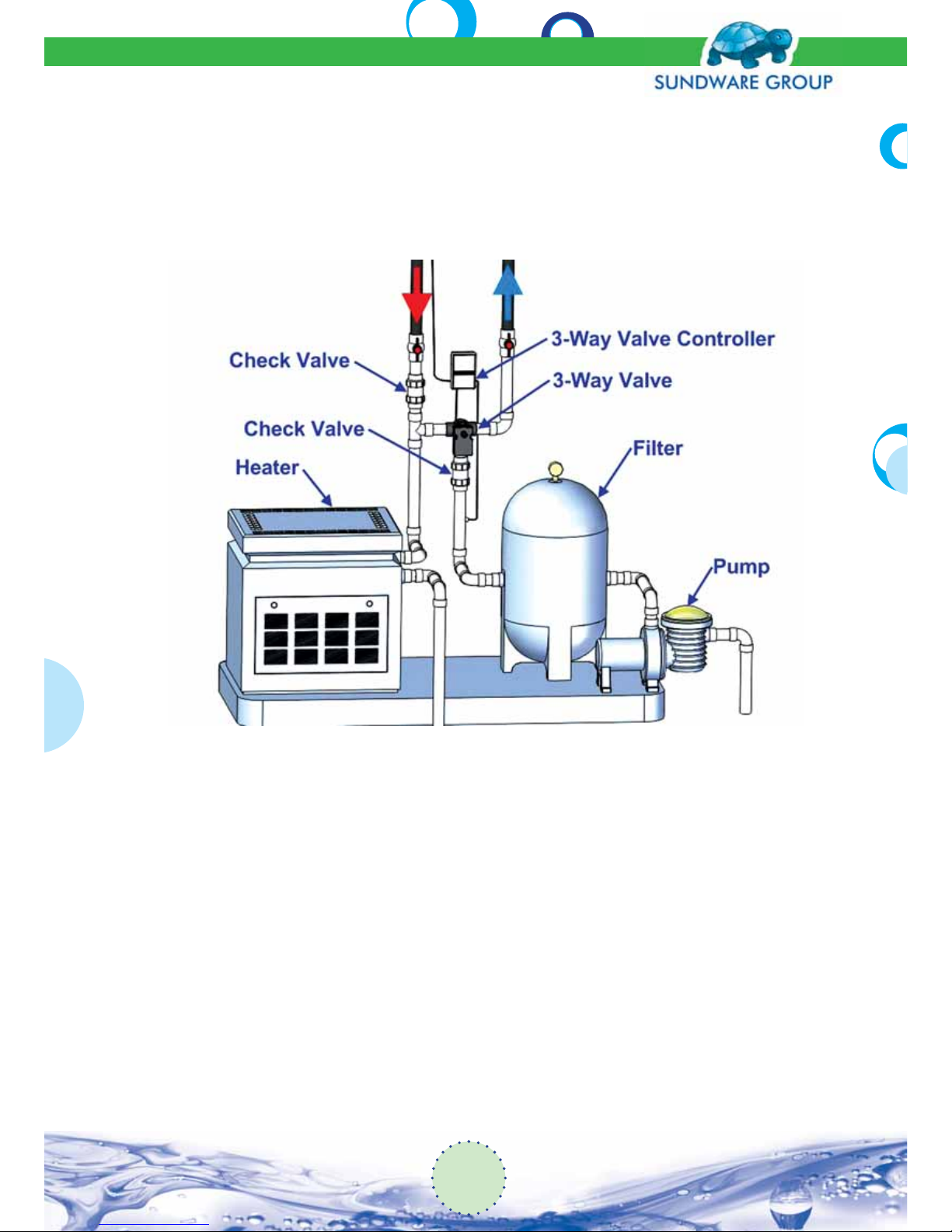
10. Bottom End Plumbing
A typical plumbing layout is shown in Fig (30). The tie-in for the solar plumbing is always downstream of the lter. You may use 1½” PVC pipe for the bottom end plumbing; however, you should
use 2” PVC pipe where possible. 2” PVC pipe is recommended above the 3-way and tee.
Always use PVC cleaner on all pipe ends and tting sockets. Use a generous amount of PVC
glue on pipe ends and tting sockets, immediately inserting with a twisting motion. Hold together for at least 30 seconds. Follow the instructions on the cleaner and glue can for proper
use. Determine the layout of all the valves and ttings before proceeding. Cut the line after
the lter in an area with enough clearance for the new ttings. Install a check valve between
the lter and the 3-way valve, with the ow pointing away from the lter (the cone inside the
check valve will be facing towards the lter). Be certain not to allow glue to seal the cone
inside the check valve.
Typically the 3-way is mounted against the wall of the building approximately 3’ to 4’ o the
ground with the side outlet facing right and the inlet facing down. Use a 2½” galvanized
pipe clamp over the bottom inlet of the valve to secure it to the wall with screws. Plumb into
the “inlet” of the 3-way valve from the check valve. The plumbing then continues up the wall,
around the eave and onto the roof feeding the solar panels. The side outlet of the 3-way
valve connects to the side outlet of the 2” tee. The return from the solar connects to the top
of the tee. The bottom of the tee returns to the line going to the pool jets. Install a check
Fig (30): Bottom End Plumbing
Solar Pool System
Installation Manual
24
Page 25
valve on the solar return line above the tee, with the direction of ow going into the tee.
Most accessories including auxiliary heaters, chlorine feeders, Pool cleaner pumps should
be on the return line after the tee. Automatic pool cleaner pumps must be run at night when
the solar is o or during the day only after the solar is already running. Failure to do so may
result in a burnt-out cleaner pump.
11. Pipe Layout
Use 2” Schedule 40 PVC plastic piping between the bottom end plumbing and the panels. White
pipe is recommended because of its excellent outdoor life. The pipe may be painted with a good
outdoor paint to match the structure or roof. 1½” pipe may be used on splits between panel rows.
All plumbing should allow for gravity drain. In tropic or sub-tropic climates, the panels and plumbing may be level; in northern climates, they must be installed with a ¼” per foot slope towards
the pool equipment. The panels should gravity drain back to the pool. If it is not possible to route
plumbing to allow for panel drainage, a manual drain valve or line should be installed, or the end
plugs may be removed to drain panels. Support all pipes every 4’ using 2½” Galvanized Pipe Clamps.
12. Control Installation
12.1 Solar Controls
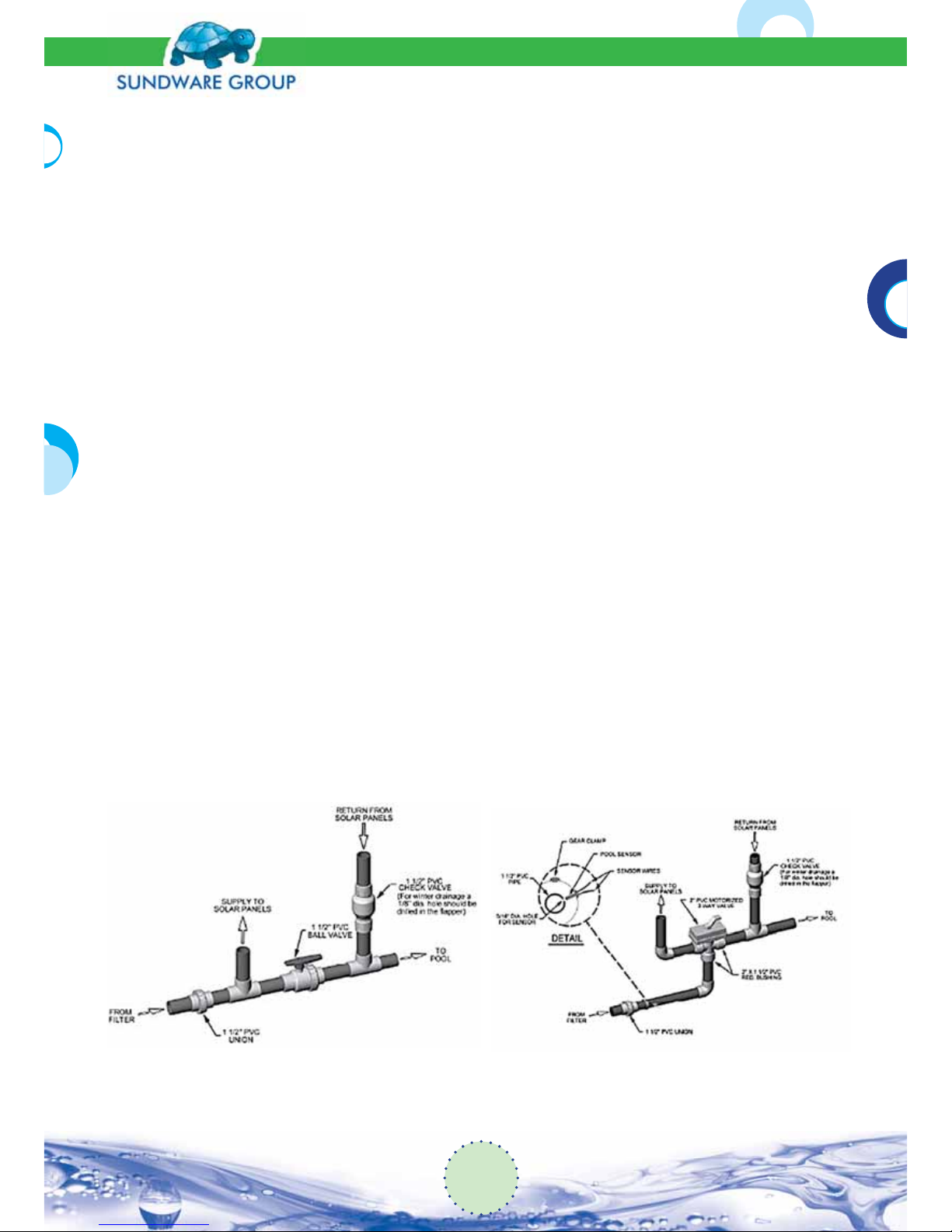
Several types of solar controllers are available. The most common utilize a 3-way diverter valve (see
gure 32) todivert water from the normal lter loop to the solar panels. Other models use a 2-way
valve (see gure 31) to blockwater from the normal lter loop, forcing it through the solar panels.
Both 3-way and 2-way are currently available inautomatic or manual versions. Some automatic systems have a manual over-ride which allows manual operation ofthe valve without electrical power.
Fig (31): Manual Control
Fig (32): Automatic Control
25
Solar Pool System
Installation Manual
Page 26
With very few exceptions, all solar controllers are compatible with our Techno-Solis solarpanels.
The major considerations in selecting a control system should be:
• reliability and proven track record,
• availability of servicing should something go wrong,
• conformity with local electrical and plumbing codes,
• Compatibility with planned installation, i.e. 2-way valve systems often cause signi cant heat
losses from night timecirculation if solar panels are at the same height, or below, the pool
and cannot drain when the system is o .
12.2 Typical Automatic Control System
Automatic control systems will turn on and o the Solar Heating System depending on availability of energy and the set temperature of the pool. Most controls operate a 2 or 3-way valve
to divert water to the solar panels.
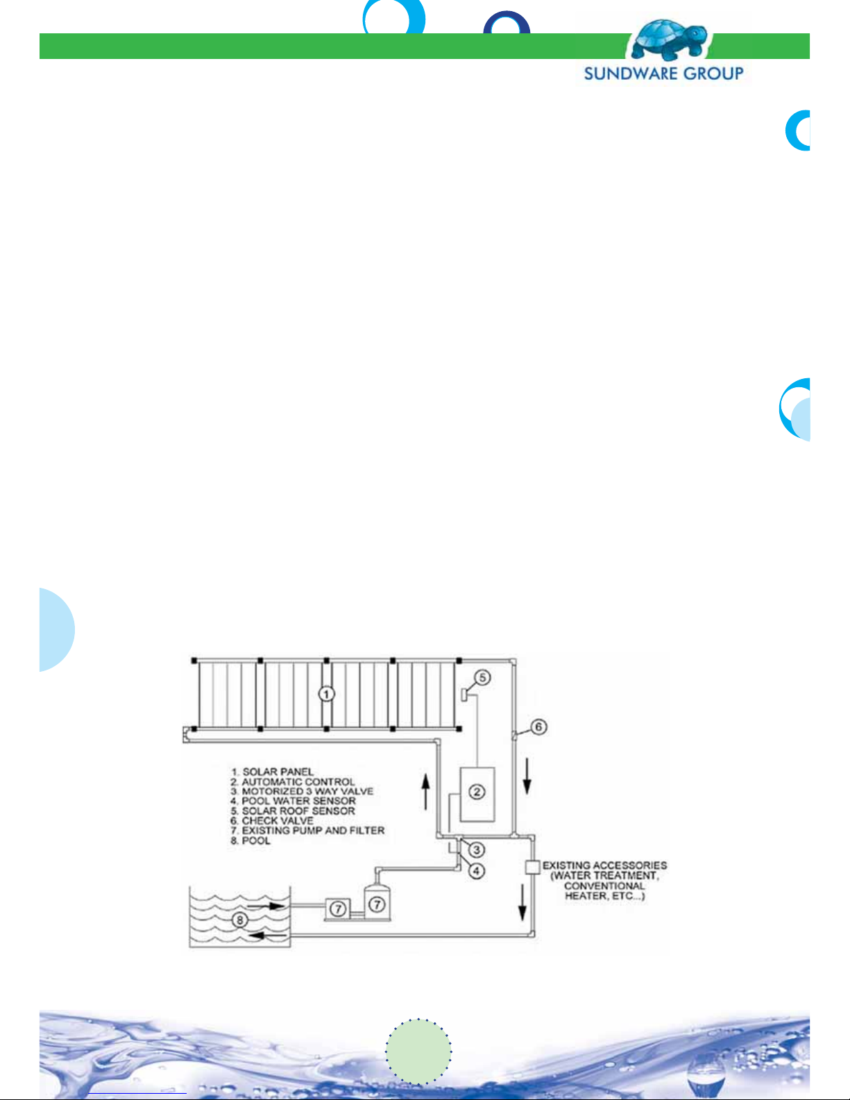
The following describes a typical 3-way automatic control system, its components and operation (see gure 32).Always refer to the SUNDWARE catalog for the exact details of operation,
maintenance and installation.
Mount the automatic control system in a convenient location near the pump and existing pool
piping. In most pool con gurations, the pump draws water from the skimmer and the main
drain. It then pushes water through the lter, the existing accessories (water treatment, conventional heater, etc...) and back to the pool. Plumbing connections for the automatic solar controller are made between the lter and the existing accessories, so that the solar heated water can
return to the pool via the existing accessories-if there is one (see gure 33).
Fig (33): Piping Diagram
Solar Pool System
Installation Manual
26
Page 27

12.3 System Check Start-Up
1. Turn the pool on and let it run 10 minutes before turning on the Solar Pool Heating System.
2. Turn the automatic controller to the “ON” position and for the manual controller open the 2
or 3 way valve slowlyand check the following:
a. the pool lter pressure gauge will indicate an increase in pressure.
b. the pool outlets may bubble for a few minutes as the air in thesolar panels is purged.
3. Retighten all EPDM panel hoses while the system is on and check piping for leaks.
4. Touch the surface of the panels. The surface of the solar panels should be cool to the touch
as the water in thepanels absorbs the sun’s energy. If the solar panels are uniformly cool to
the touch, then our SolarPool Heating System is operating properly.
12.4 Typical Automatic Control Components(see gure 33)
• the electronic control box, 110 or 220 volt (2)
• the motorized 3-way valve, 24 volt (3)
• the solar roof sensor (5)
• the pool water sensor (4)
12.5 Typical control Operation(Les Fonctions
du ContrôleAutomatique)
When the pool pump is running:
1. “AUTO, TEST ON or OFF” switch:
AUTO: when the switch is in this position, the control will automatically divert water ow to
thesolar panels if su cient solar energy is available and the pump is on.
TEST ON: the water ows through the panels, regardless of the pool temperature or the solar
energyavailable. Often uses for night cooling.
OFF: The panels are bypassed and the water ows directly to the pool.
2. Thermostat:this should be positioned to turn o the Solar Pool Heater when the selected
temperature has beenreached.
3. Green Light “FLOW THRU COLLECTORS”:this light will come on whenever the water is diverted to the solar collectors.
27
Solar Pool System
Installation Manual
Page 28

13. Special Roof Requirements
Variations in the installation procedures are outlined below. Consult the technical support for
other types of roof installations.
13.1 Flat Tile or Barrel Tile Roofs:
The mounting hardware is attached to the tile using Tapcon Screws supplied with the kit (you
must specify tile roof when ordering). This requires drilling a pilot hole in the tile before inserting
the screw. Use a 3/16”masonry drill bit. DO NOT drill into the substrate below the tile; doing so
will cause a roof leak. The mounting screws should be positioned 1”to 2”above the bottom edge
of the tile. This will allow a space between the tile and the substrate due to the overlap in the
tiles. On barrel tile roofs, try to lay out the panels so that the mounting holes fall on the tops of
the barrel tile. This can be accomplished by using 6” rubber couplings where additional spacing
is required; cut the coupling to the correct length.
13.2 Cedar Shake Roofs:
If the cedar shakes are installed on top of a plywood surface, use a galvanized metal ashing
(approximately 4”x4”) under each shake where the mounting screw will penetrate. Center the
ashing under the penetration location before installing the screw. Drill a pilot hole and apply
a generous amount of sealant into the hole. If the cedar shakes are installed on r strips, call for
alternate installation method.
13.3 Flat Built-up Gravel Roofs:
Use caution when installing on this type of roof. The preferred method is to have a roo ng contractor install “roof curbs” where the mounting hardware will be installed.
13.4 Open Beam Roofs
Any ceiling with exposed beams must be checked to avoid the screw ends from penetrating into
the interior space.
13.5 Metal Roofs
If the metal roof is installed on a plywood surface, you may proceed using the normal installation
method. If the metal roof is installed on r strips, the mounting hardware must penetrate into
the r strip to insure a good seal and to avoid bending the metal surface.
13.6 Rubber or Asphalt Modi ed
This type of roof is typically installed at. Using a 2” to 2-½”fender washer under the mounting
hardware will provide additional mounting surface. Be sure to use a generous amount of sealant
under the washer, between the washer and the mounting hardware, and the top of the mounting screw.
13.7 Roof or Ground Mounted Rack Systems
Rack systems can be made from pressure treated wood or aluminium. For roof mounted racks
aluminium is preferred for its additional strength and longevity. Aluminium racks are available
in a kit form.
Solar Pool System
Installation Manual
28
Page 29

14. Operating and Check-Out Procedures
1. Final Visual Inspection
Check the following items:
• Verify that the check valves, control valves and vacuum breakers are installed properly.
• Verify that all plastic collector clamp clips are tight.
• Verify that all lag bolts are secure and that adequate sealant was used to prevent any roof
leaks.
• Be sure all collector riser tubes are snapped into the spacer bars (except where they go around
obstructions).
• Be sure that collector riser tubes are NOT rubbing on the roof surface between spacer bars. If
they are, adjust spacer bars as needed to prevent this or a hole may develop in the riser tube.
• Be certain that the system will automatically drain down when the pump is shut o or that
enough manual drain valves have been included.
• Verify that all pipe runs are properly supported with pipe clamps.
2. Turning the System On
• Turn o the pool pump.
• Turn the 3-way valve so that the “closed” indicator points toward the pool side of the valve.
• Be sure that the ball valves on the feed and return lines are open.
• Turn the pool pump on.
• Set the pool pump timer, if used, so that the pump will run when sun is shining on the solar
collectors. Usually 10:00 AM to 4:00 PM, but this will vary with geographic location, time of
year and the compass location of the system.
• When the solar system is running, you should notice: “Aslightly higher pressure reading on the
pressure gauge”.
At midday, if the sun is out, warmer water should be coming into the pool. This water should
be 3 to 5 degrees warmer than the pool temperature.
All the collectors should feel cool to the touch when the sun is on them. (If they are not, see
the troubleshooting section).
• During the cooler months of the year, it is essential that the pool surface be covered at night
with a “pool blanket” to maintain a comfortable water temperature. Low nighttime temperatures can lower the water temperature more than the solar can recover during the day.
29
Solar Pool System
Installation Manual
Page 30
3. Turning the System O
• Turn the pool pump o .
• Turn the 3-way valve so the “closed” indicator points toward the solar side of the valve.
• If isolating the collectors, close the ball valves on the feed and return lines after you are sure all
the water has drained out of the collectors and plumbing.
• Turn the pool pump on to lter the pool as needed.
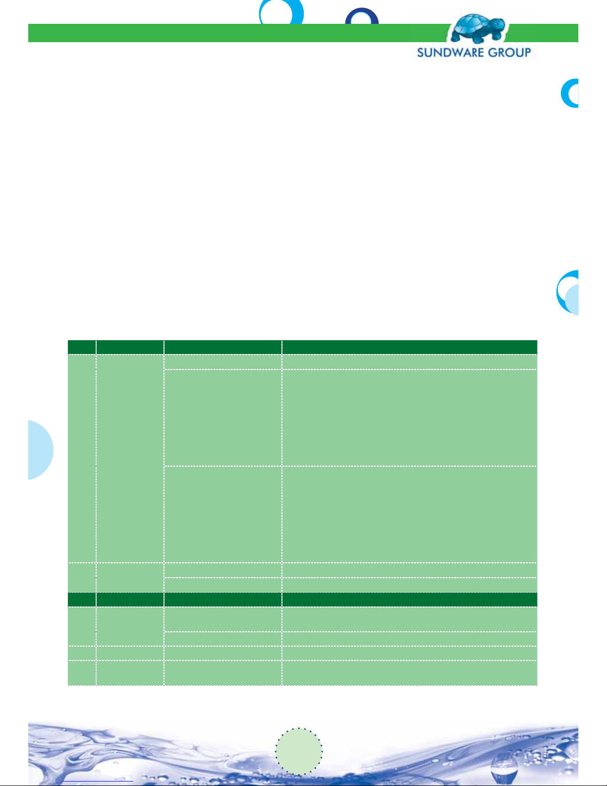
15. Troubleshooting Guide
The troubleshooting guide outlines procedures for determining and correcting problems which
may occur with the SUNDWARE Solar heating System. It deals with problems, components and
corrective action. Several common problems are outlined with simple corrective measures which
may be made by the homeowner.
SN PROBLEM COMPONENT “C”
1
Air bubbles in
the pool during
the operation of
the system
Filter is dirt Dirt in lter reduces ow to collectors.
Vacuum relief valve of the
pump (if available).
No enough water pressure in
the solar system to keep the
vacuum relief valve closed so
it is allowing air to be drawn
into the water as it ows by the
valve.
a. Backwash to reduce pressure.
b. If an older system, check for debris or scale in the mouth of the
vacuum relief valve and clean (if necessary).
c. Move vacuum relief valve, and put solid end cap at end of top
header where vacuum relief is located.
d. Install a2-Way Valve on the return line to throttle the ow back to
produce more back pressure on system.
e. Eliminate the Vacuum Relief Valve.
f. Increase pump horse power.
Pump is making noise, which
could make the air coming into
the pump because the pump
is working harder to move the
water through the solar system
a. Tight the pump trap lid.
b. Check, clean, lubricate or replace the O-ring on the pump trap lid.
c. Remove the suction pool cleaner (if available). The air bubbles
should be improved. Use it only during the o of the system.
d. If you have a clear lid on the pump and can see air bubbles in the
trap, using a garden hose, run water over the lid and each joint
individually to see if the air bubbles clear up. If there is not a clear
lid, listen to pump noise for a smoother operation. Repair any air
leaks.
2 Leaks
Piping Repair with PVC or CPVC cement.
Valves Replace O-rings or seals as required or replace the valve.
SN PROBLEM COMPONENT “C“
3
Automatic
control does not
work on “AUTO”
Pool set temperature
The pool has reached the desired temperature asset by temperature
thermostat. If the pool is too cool increase the thermostat setting.
Sensors Test sensors (manuf. instructions).
4 Pooloverheats Set temperature Set thermostat to the desired pool temperature.
5
Control stays
“ON” at night
Warm night
The solar panels are warmer than the pool water. This is a common
occurrence in the springtime when the pool water is very cold.
Solar Pool System
Installation Manual
30
Page 31

6
Control does not
work
Power supply Check fuses, circuit breakers and wiring to the controller.
Wiring Remove cover plate and check for loose wires
Motorized valve
Measure the voltage at the valve motor terminals with a voltmeter
and ip the “TEST ON and “OFF” switch. If the voltage is correct and
the valve does not turn, it must be replaced.
Valve
The motor forces but the valve will not turn.Sand from a worn lter
may jam the valveoperation. Disassemble the valve, clean it out and
replace O-rings, gaskets, ball, or entire valve if scored or damaged.
Repair or replace pool lter.
7
Some solar
panels are warm
while others are
cool
Flow of water.
No equal ow through all panels. The warm panel indicates
to low water ow.
a. Be sure lter is clean. Backwash to reduce pressure.
b. The pump may not be providing enough water to the solar
system. Check water ow using a ow meter. Increase pump
horsepower if needed to maintain recommended ow.
c. If there is a suction type cleaner in the pool, remove it. If this elimi-
nates the problem, use it only when the solar system is o .
If the system is a single row
array
a. If there is adequate ow, install an HC-152 Two-Way Valve on the
return line to throttle the ow back to produce more back pres-
sure on the system. This will even out the ow through the panels.
b. If the array contains more panels than the maximum recommend-
ed on Page 9 of the manual, change the array to a double row or
single row split feed as shown in Fig 4.2 and Fig 4.3.
If the system is a double row or
a single row split feed array.
a. If there is adequate ow, install an HC-152 Two-Way Valve on the
return side of the set of panels that are the coolest to throttle
back the ow through these panels and force more through the
warmer panels.
b. If any section of the array contains more panels than the maxi-
mum recommended on Page 9 of the manual, make changes as
needed to correct this.
8
The water coming from the
solar system is
not as warm as it
should be
The water is owing to fast
through the panels.
Water ow through a single panel should be less than 10 gallons per
minute. Adjust the Three-Way Valve to by-pass some of the water
Seasonal normal operation
In the cooler months of the year, the temperature rise through the
panels may only be 2°-3°. Use the back of your hand to feel the water
temperature di erence at the pool return inlet
9
The 2-way or
3-way valve not
turn
Internal parts need to be lubricated orreplaced
If valve has a grease tting, inject grease into valve then turn the diverter past the grease tting to spread the grease. If the grease tting
is dry, ll it with silicone grease. If there is not a tting, disassemble
valve and lubricate with silicone grease. Replace worn or broken parts.
31
Solar Pool System
Installation Manual
Page 32
EUROPE
THE MARKETING TEAM
SUNDWARE TRADING LTD
77 STROVOLOS, STROVOLOU
NICOSIA, CYPRUS
TEL: +357-22-589371
MOB: +357-22-99-266919
EMAIL: [email protected]
NORTH AMERICA
TEL: 1 888 765-2473
www.techno-solis.com
 Loading...