

Page 1
Drawn up by:
2009-02-03 / RK
OI06H-4018 SR 590
Revision:
01
Reviewed:
Page:
1 of 22
Operating Instruction
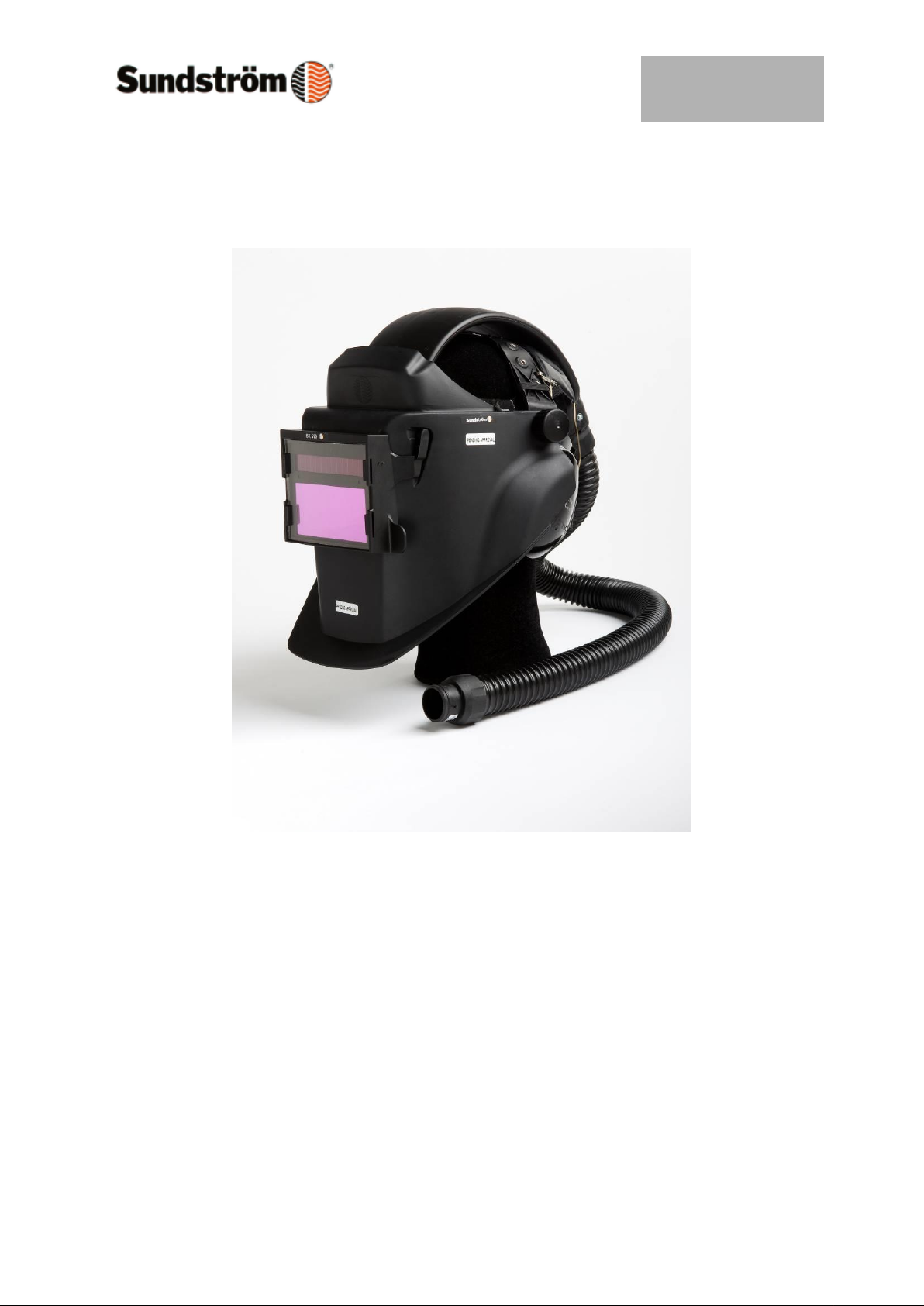
SR 590 Welding shield
Page 2

Drawn up by:
2009-02-03 / RK
OI06H-4018 SR 590
Revision:
01
Reviewed:
Page:
2 of 22
General information
The Sundström SR 590 welding shield is used together with the
Sundström SR 500 battery-powered fan unit and is designed
for protecting the user against inhaling harmful and irritating air
pollutants and against radiation and weld spatter during arc
welding, MAG welding and TIG welding.
SR 590 is in one size.
The SR 590 welding shield together with fan SR 500 is approved in
accordance with EN 12941:1998, TH3.
When selecting equipment for SR 590 some of the factors that
should be taken into account are as follows:
• Type of pollutant
• Concentrations
• Work intensity
• Protection requirements in addition to respiratory protective advice.
Risk analysis should be carried by a person who has suitable
training and experience in the area.
Instructions for use for SR 590 should be read before use.
Page 3
Drawn up by:
2009-02-03 / RK
OI06H-4018 SR 590
Revision:
01
Reviewed:
Page:
3 of 22
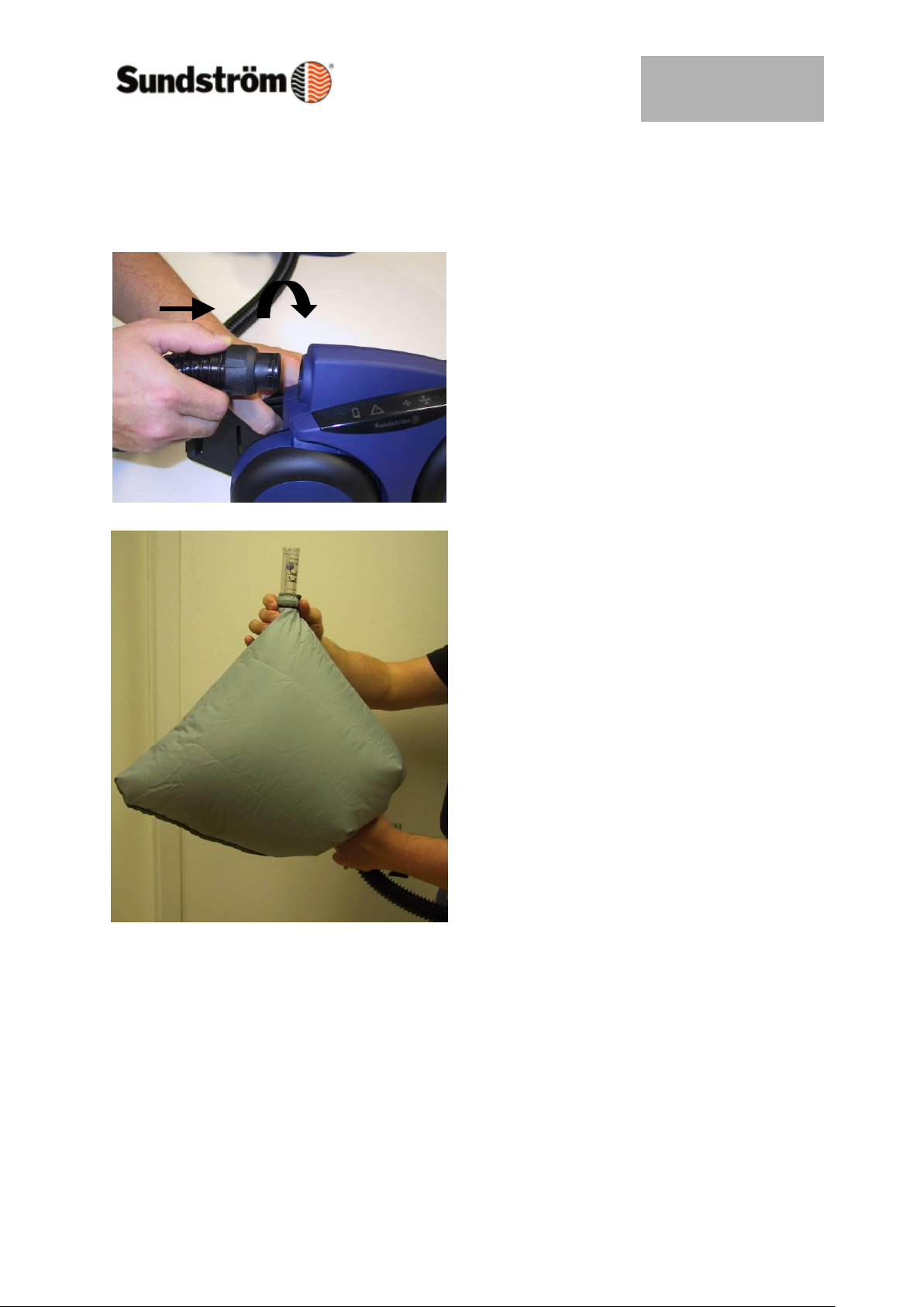
4.1 Check flow
Before the check, also read the user
instructions for fan SR 500.
Start fan the fan
Connect the hose from the visor to the
fan unit (or compressed air equipment)
turn the coupling 1/8 of a turn.
Place the head top in the flow meter and
start the fan unit.
Grip the lower part of the bag to seal
around the breathing hose.
Grip the flow meter tube with the other
hand so that the tube points vertically
upwards from the bag.
Read the position of the ball in the tube.
This should hover at a level with or
slightly above the upper marking on the
tube.
If minimum flow is not achieved,
check that:
– The flow meter is held upright.
– The ball moves freely.
– The bag seals well around the hose.
Page 4
Drawn up by:
2009-02-03 / RK
OI06H-4018 SR 590
Revision:
01
Reviewed:
Page:
4 of 22
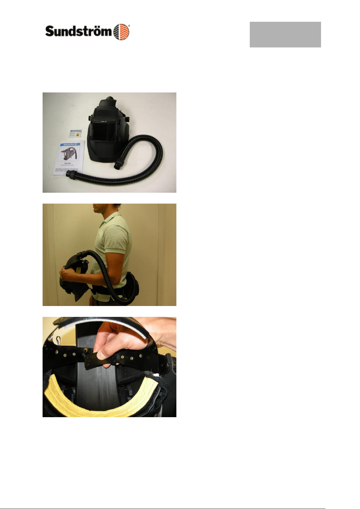
4.2 Putting the shield on
See also the user instructions for the SR
500 fan.
Check that the scale number of your lens
is correct for your work.
The shield is delivered with a welding
lens with scale No. 10.
Put the fan on your waist and adjust the
belt so that the fan is located firmly and
comfortably at the back of your waist.
Start the fan and adjust the air flow to
suit your work intensity.
Raise the front piece and put the welding
shield on.
If necessary, adjust the head harness in
height by lengthening or shortening the
strap for the top of the head.
The sweatband should be fitted just
above the eyebrows.
Page 5
Drawn up by:
2009-02-03 / RK
OI06H-4018 SR 590
Revision:
01
Reviewed:
Page:
5 of 22
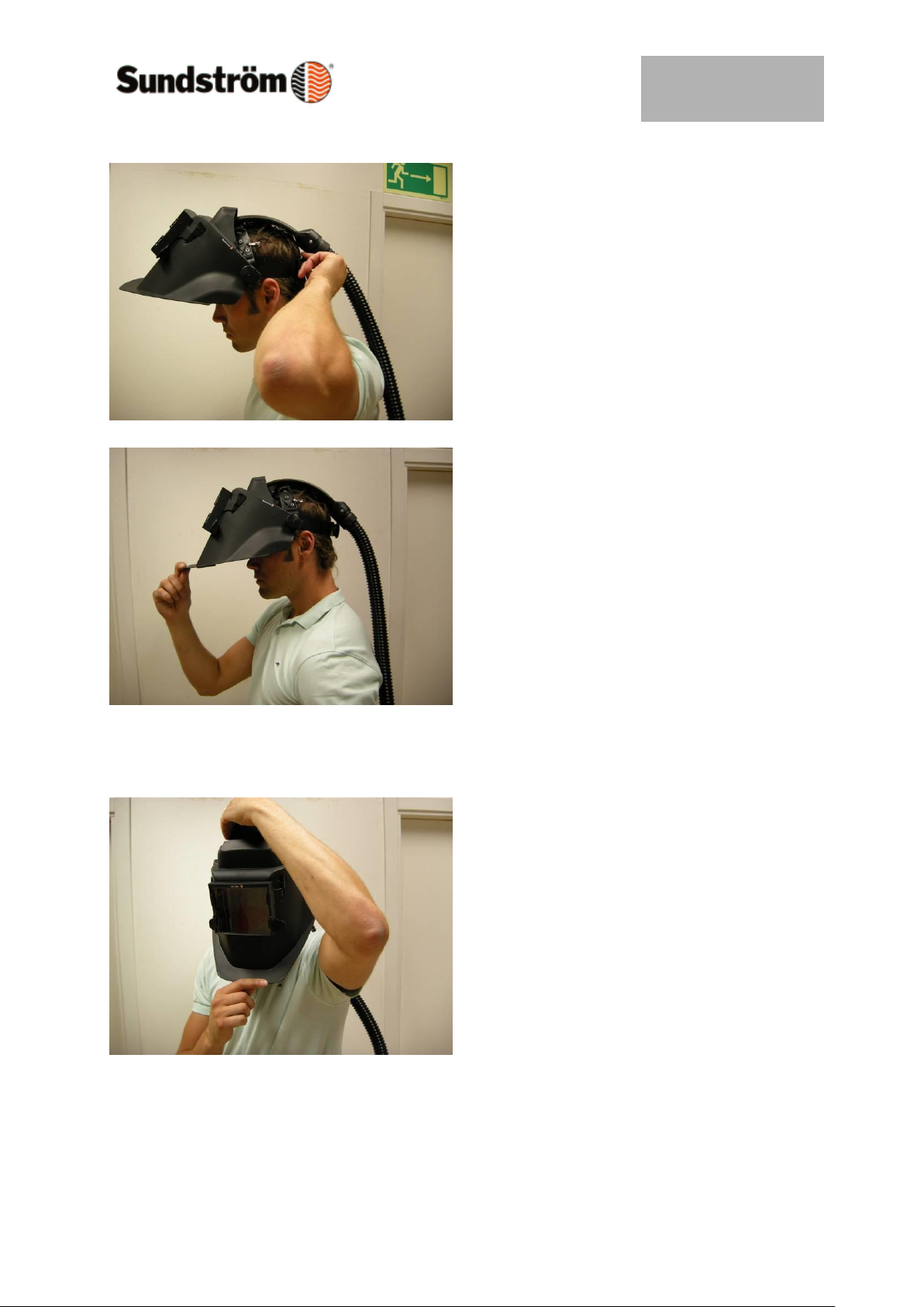
If necessary, adjust the circumference of
the head harness by means of the rear
knob. The head harness should be fixed
tight around your head.
Lower the front piece by pulling the face
seal down under your chin.
Adjust the neck size of the face seal by
means of the elastic neck strap.
Insert a finger between your cheek/chin
and the face seal and run the finger long
the contact surface of the face seal all
the way round to check that it fits well
against the face.
Check carefully that no escaping air
comes out around the cheek and chin.
Check that the front piece is in the fully
down position, no air should be coming
out from the part above the forehead.
Page 6
Drawn up by:
2009-02-03 / RK
OI06H-4018 SR 590
Revision:
01
Reviewed:
Page:
6 of 22
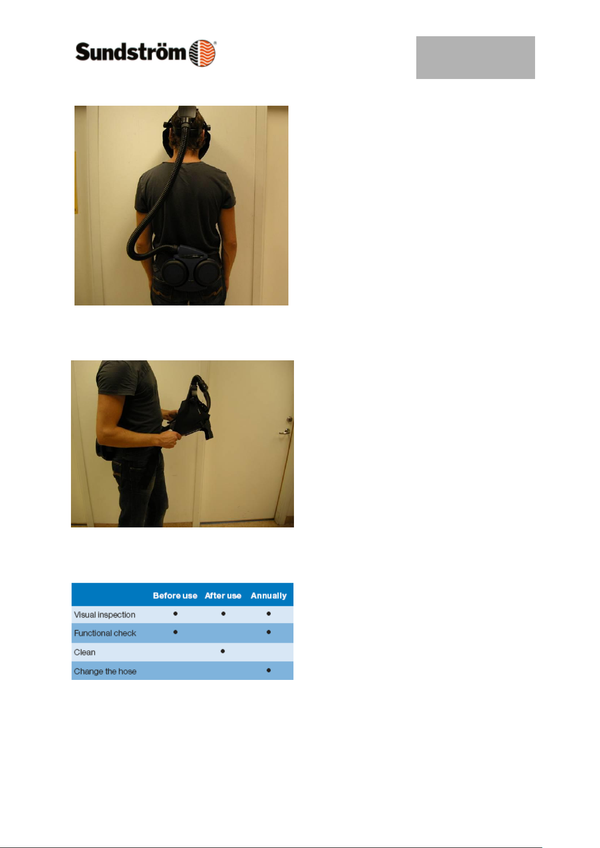
Make sure that the breathing hose runs
along your back and that it is not twisted.
4.3 Taking the shield of
Leave the polluted area before taking off
the equipment.
- Take the welding shield off.
- Switch off the fan. Release the
belt and remove the fan.
- After use, clean and check the
equipment.
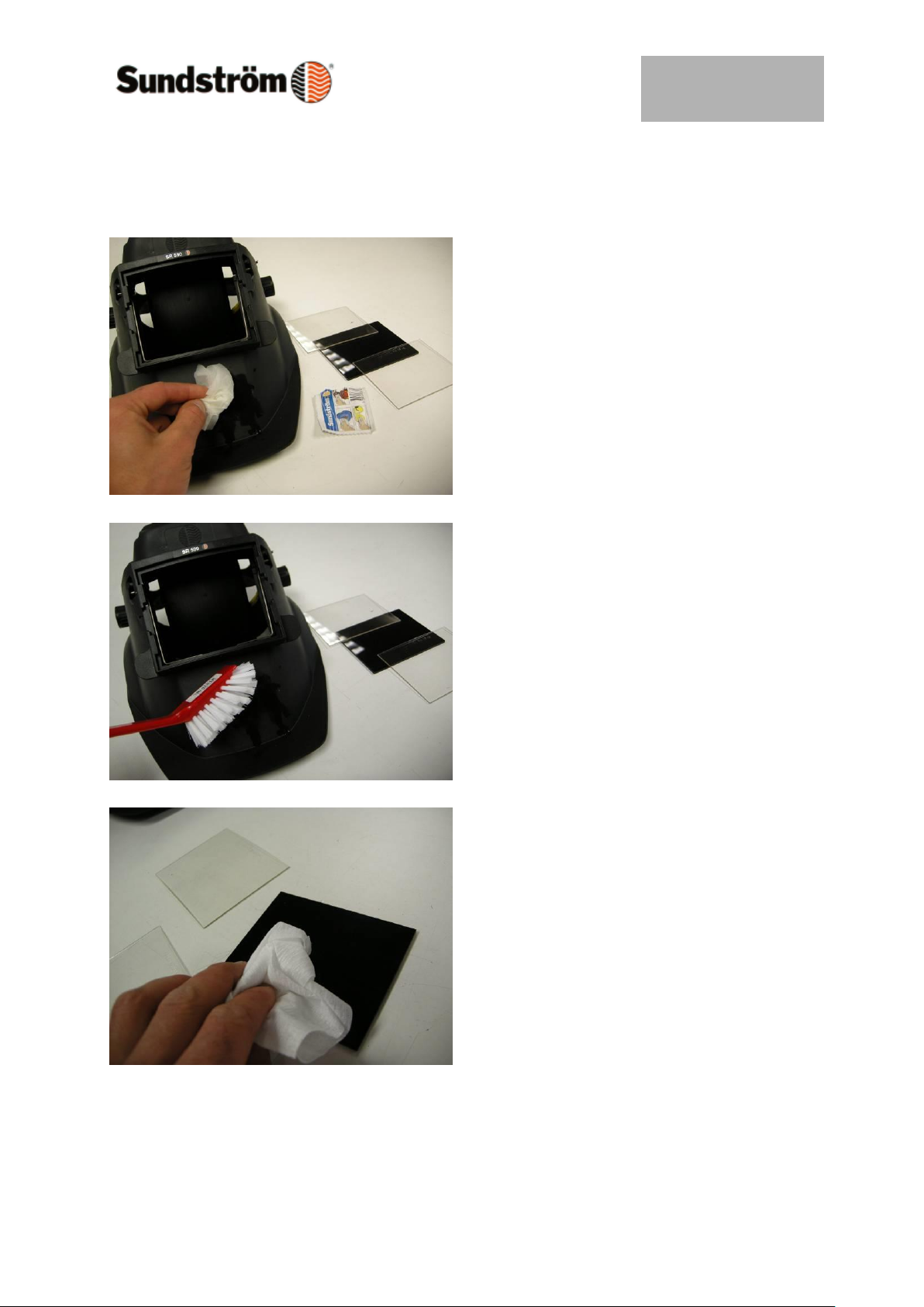
5.1 Maintenance schedule
The schedule specifies the minimum
maintenance routine requirements to
ensure that the equipment is always in
good working order.
Page 7
Drawn up by:
2009-02-03 / RK
OI06H-4018 SR 590
Revision:
01
Reviewed:
Page:
7 of 22
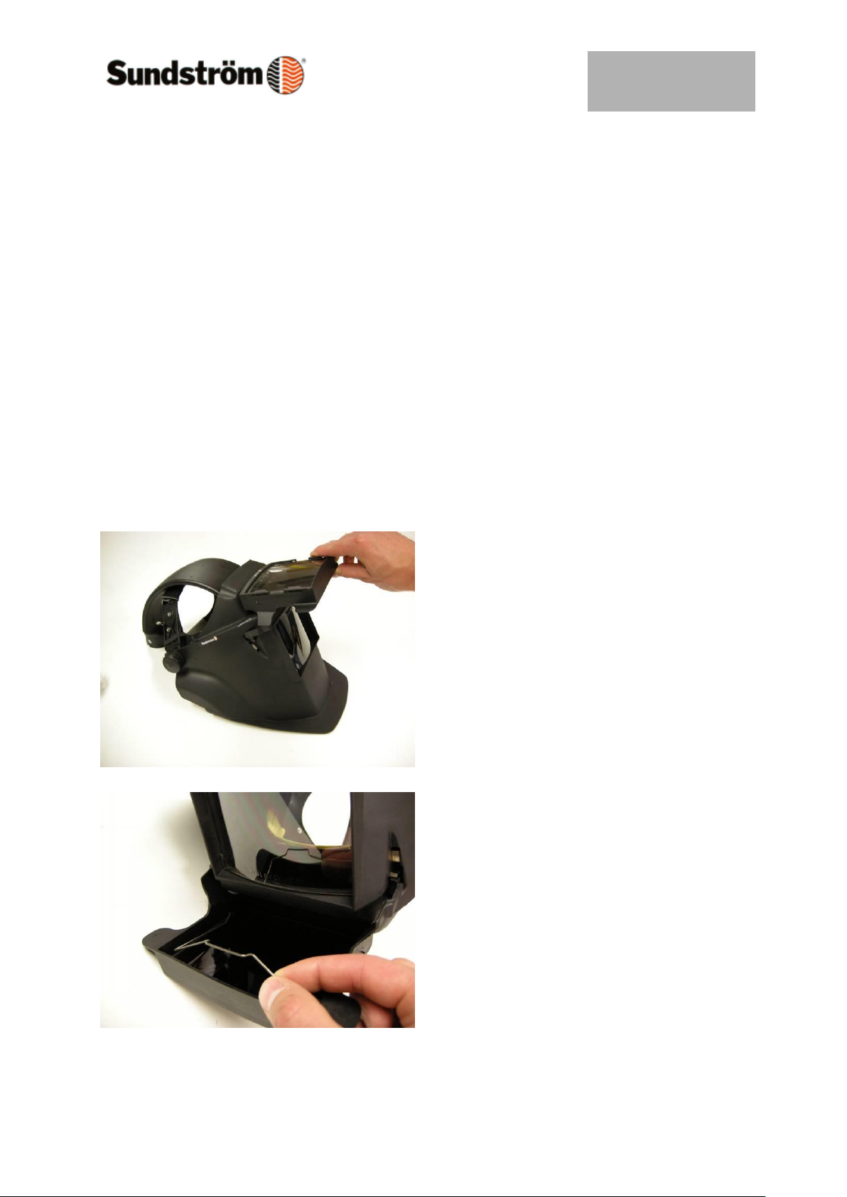
5.2 Cleaning
Remove the fan filter, battery and belt,
and remove the welding lens and
protective lens from the shield before
cleaning.
Sundström cleaning wipes SR 5226 that
clean and disinfect are recommend for
daily maintenance.
If more heavily soiled, the equipment can
be carefully blown clean with
compressed air.
However, make sure that dirt particles do
not end up in the air intake of the fan.
The equipment can then be cleaned with
a soft brush or sponge, moistened in a
solution of washing-up liquid or the like
in lukewarm water.
!! Wipe the plastic protective lens
carefully, since they are sensitive to
scratching.
!! Automatic welding lenses are very
sensitive to moisture. Use only a dry
polishing cloth.
!! N.B. Never clean with a solvent.
Page 8
Drawn up by:
2009-02-03 / RK
OI06H-4018 SR 590
Revision:
01
Reviewed:
Page:
8 of 22
5.3 Storage
After cleaning, store the equipment in a
dry and clean place at room
temperature.
Avoid direct sunlight or other sources of
heat.
The fan filters should best be stored in a
tight plastic bag.
The battery can be stored in the
Sundström charging station SR 506.
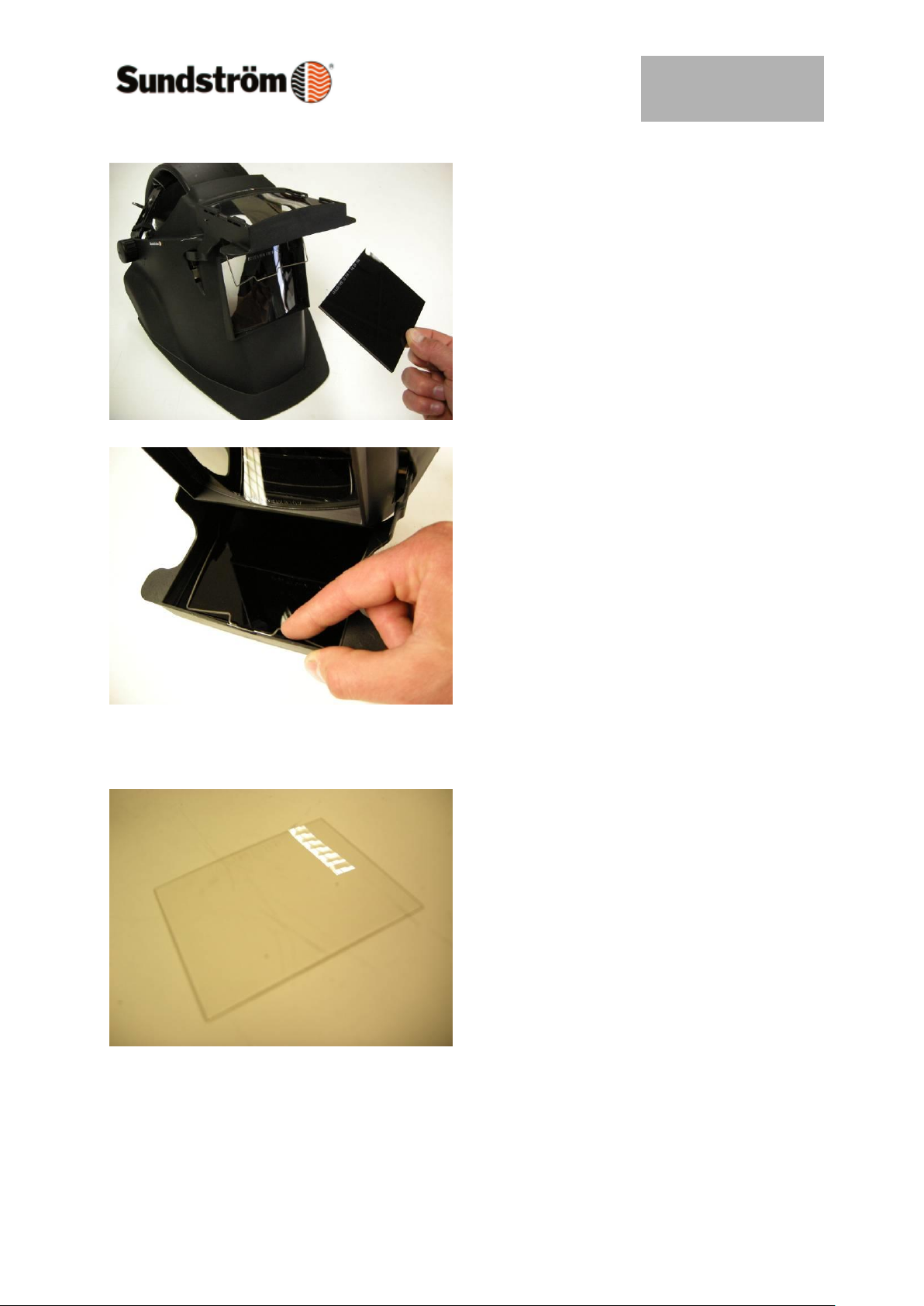
6.1 Changing the welding lenses
The welding lens should be marked with
the scale number and approval symbol.
Raise the welding lens flap.
Use your fingers to release the spring.
Page 9
Drawn up by:
2009-02-03 / RK
OI06H-4018 SR 590
Revision:
01
Reviewed:
Page:
9 of 22
Change the welding lens.
Fold the spring back.
6.2 Changing the inner protective lens
The inner protective lens is fitted in the
front piece behind the welding lens flap.
Page 10
Drawn up by:
2009-02-03 / RK
OI06H-4018 SR 590
Revision:
01
Reviewed:
Page:
10 of 22
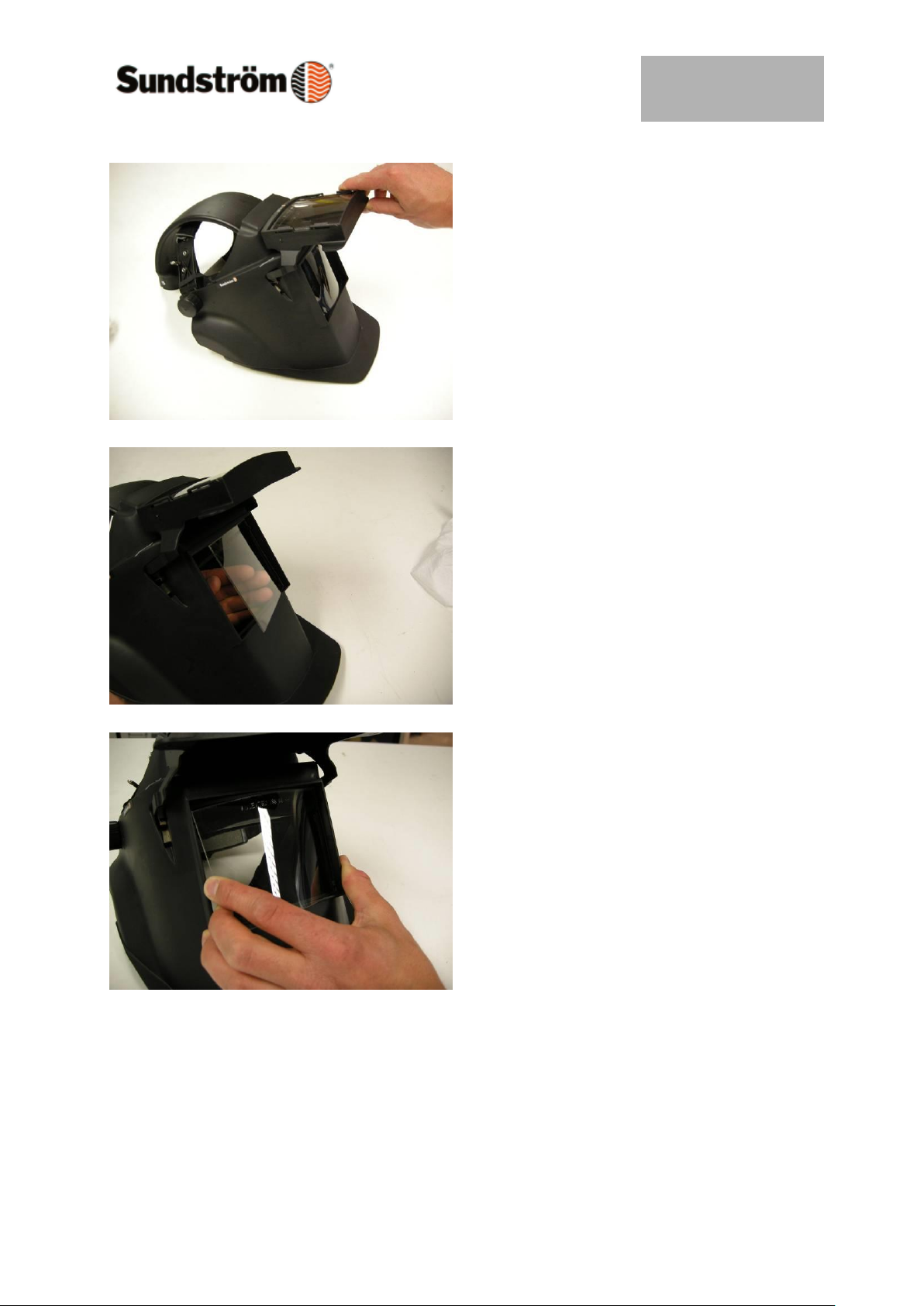
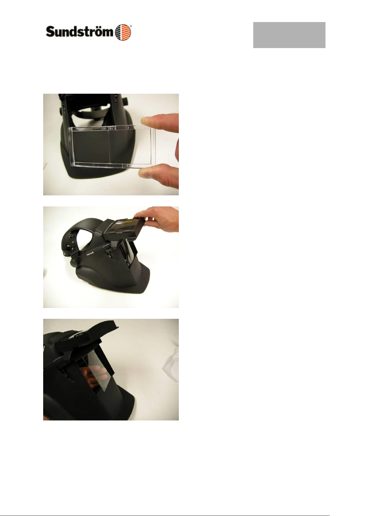
Raise the welding lens flap.
Press the protective lens out with your
fingers from the inside of the shield.
Fit the new protective lens from the
outside.
Never use an inner protective lens made
of glass - risk of injury
by glass splinters.
Page 11
Drawn up by:
2009-02-03 / RK
OI06H-4018 SR 590
Revision:
01
Reviewed:
Page:
11 of 22
6.3 Fitting the correction lens
Correction lenses are available as
accessories in four strengths
ranging from 1.0 to 2.5 dioptres.
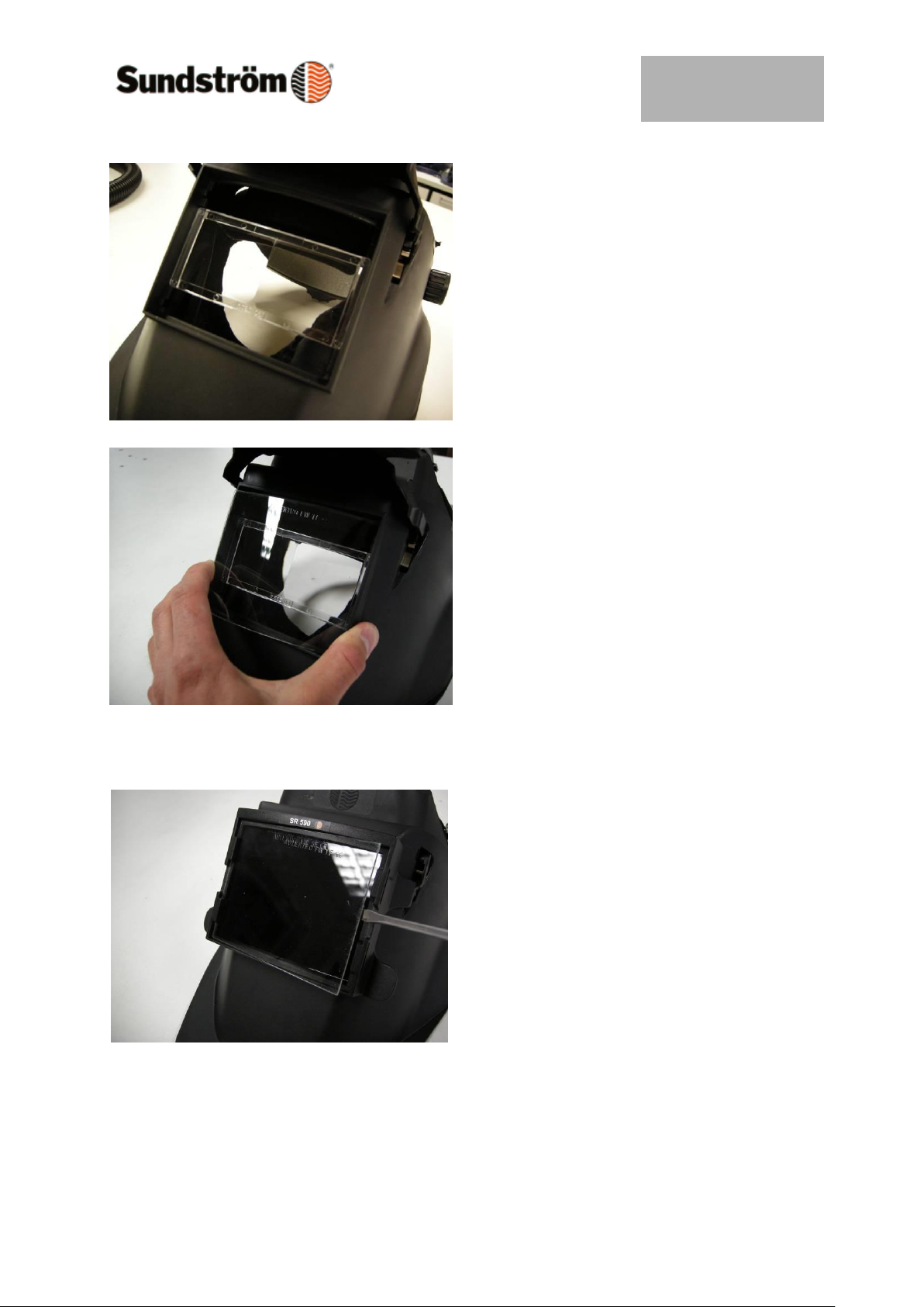
Raise the welding lens flap.
Press the protective lens out with your
fingers from the inside of the shield.
Page 12
Drawn up by:
2009-02-03 / RK
OI06H-4018 SR 590
Revision:
01
Reviewed:
Page:
12 of 22
Place the correction lens so that it rests
in the groove on the sides of the
opening.
Fit the protective lens.
6.4 Changing the outer protective lens
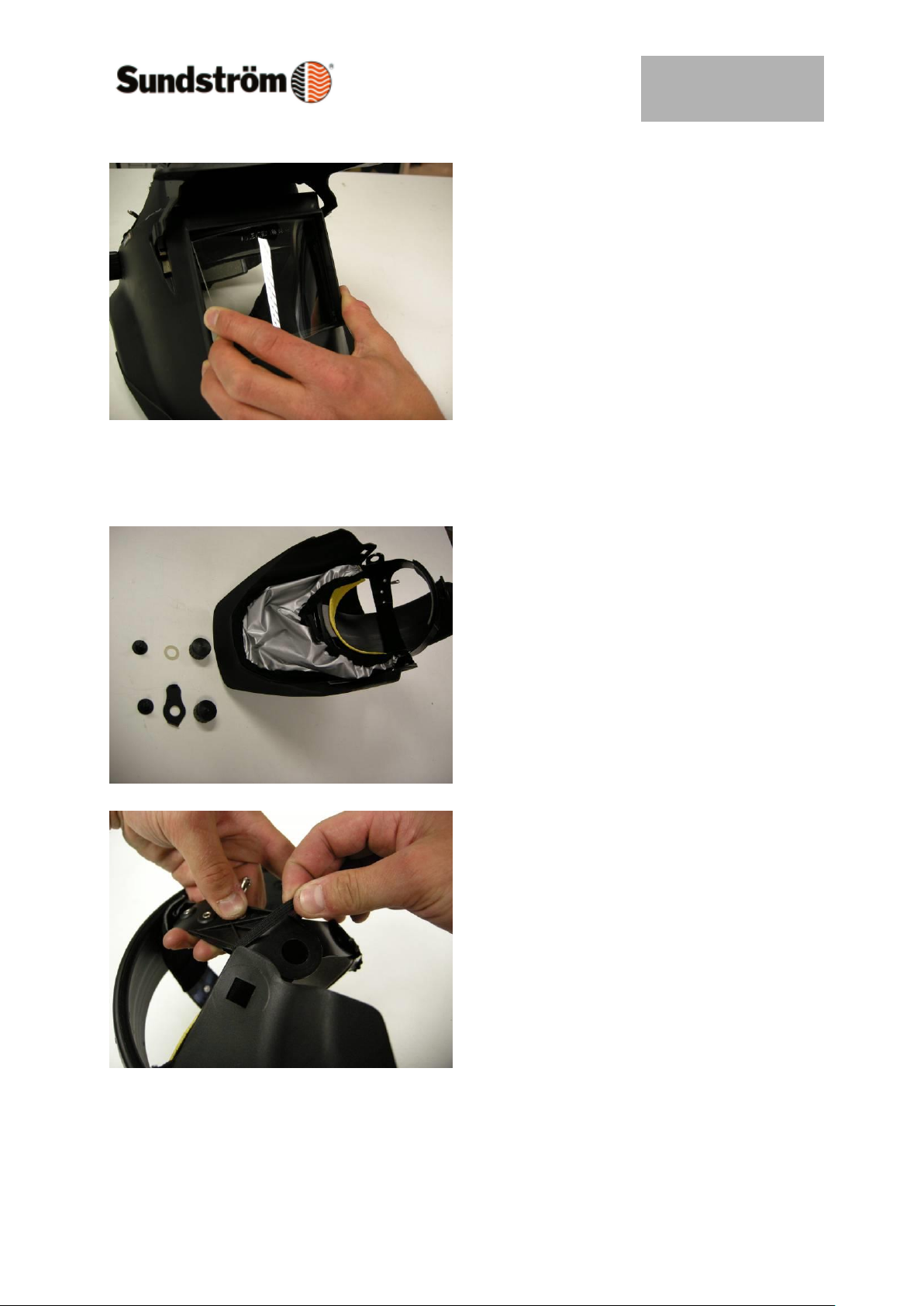
The outer protective lens is located in
front of the welding lens.
Use a blunt object to press the short side
of the protective lens so that the lens is
bowed and can be removed from its
mountings.
Page 13
Drawn up by:
2009-02-03 / RK
OI06H-4018 SR 590
Revision:
01
Reviewed:
Page:
13 of 22
Fit a new protective lens.
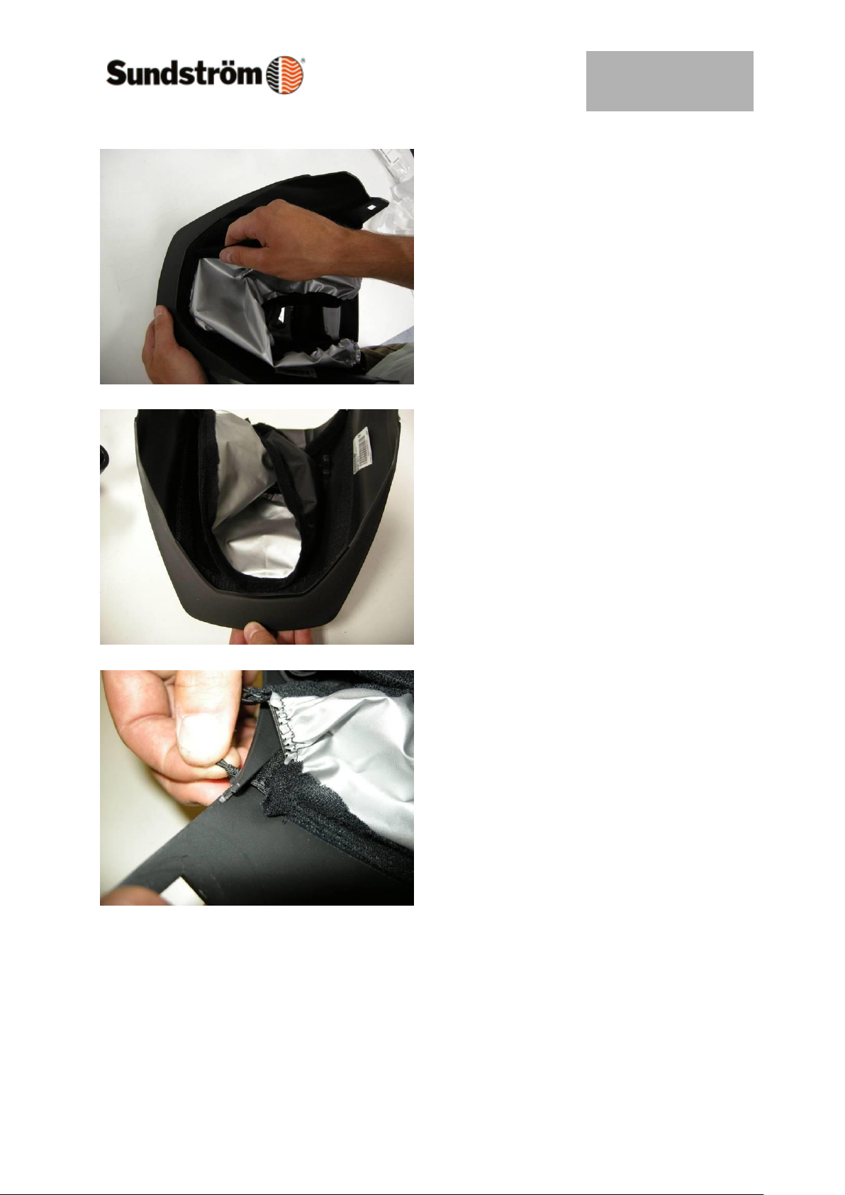
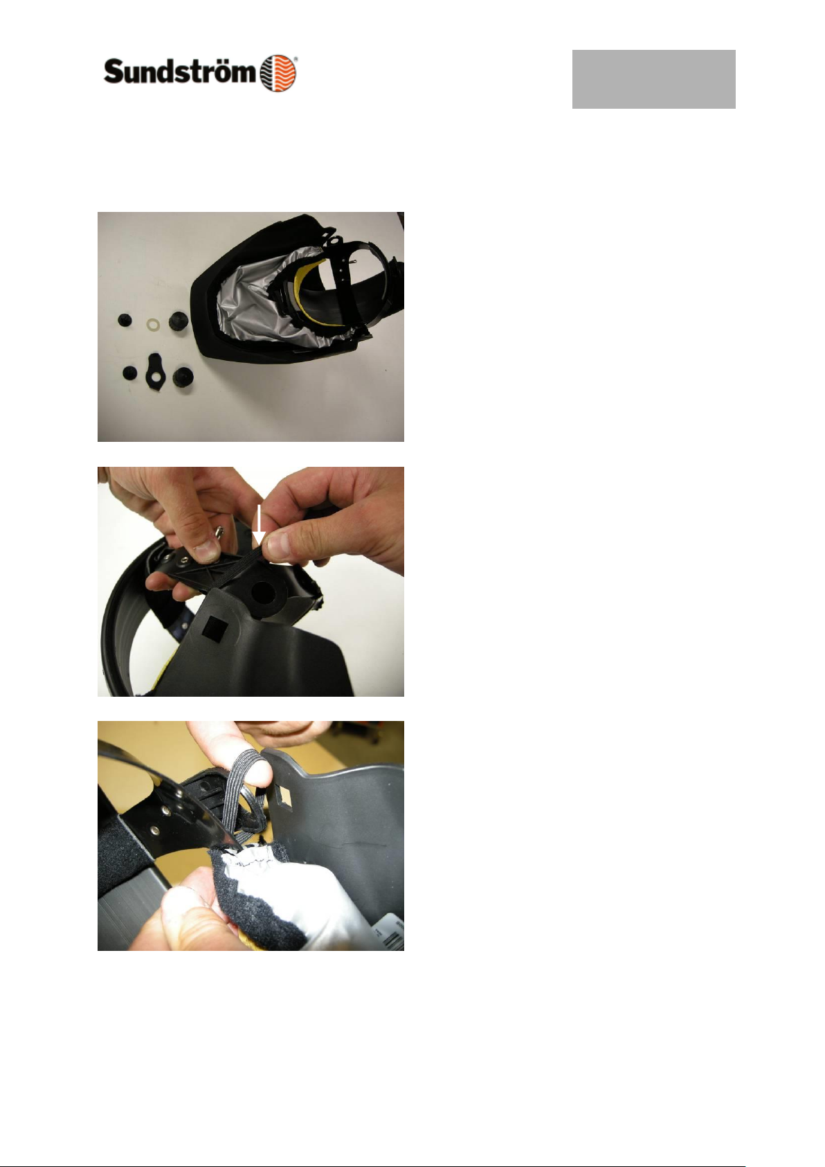
6.5 Changing the face seal
The face seal is secured to the front
piece by means of Velcro tape and four
rubber bands, two on each side.
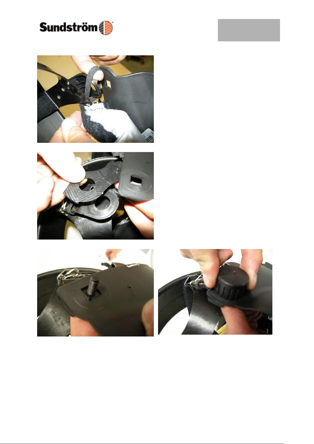
Remove the head harness by releasing
the two side knobs. Save the mounting
parts (knob/screw/washer*)
Release the rubber bands from the head
harness and from the front piece.
Page 14
Drawn up by:
2009-02-03 / RK
OI06H-4018 SR 590
Revision:
01
Reviewed:
Page:
14 of 22
Carefully pull off the face seal.
Secure the new face seal to the Velcro
tape, starting in the centre of the front
edge of the front piece.
Secure the narrow rubber band to the
slot on the front piece.
Page 15
Drawn up by:
2009-02-03 / RK
OI06H-4018 SR 590
Revision:
01
Reviewed:
Page:
15 of 22
Fit the head harness back to the front
piece, but before securing it in position,
secure the wider rubber band around the
side arms of the head harness.
Screw the head harness in position.
Make sure that the pin on the special
washer fits into the hole in the front
piece.
The washer on the right-hand side of the
shield also determines the end positions
when the front piece is raised and
lowered.
This is the reason for its design.
Page 16
Drawn up by:
2009-02-03 / RK
OI06H-4018 SR 590
Revision:
01
Reviewed:
Page:
16 of 22
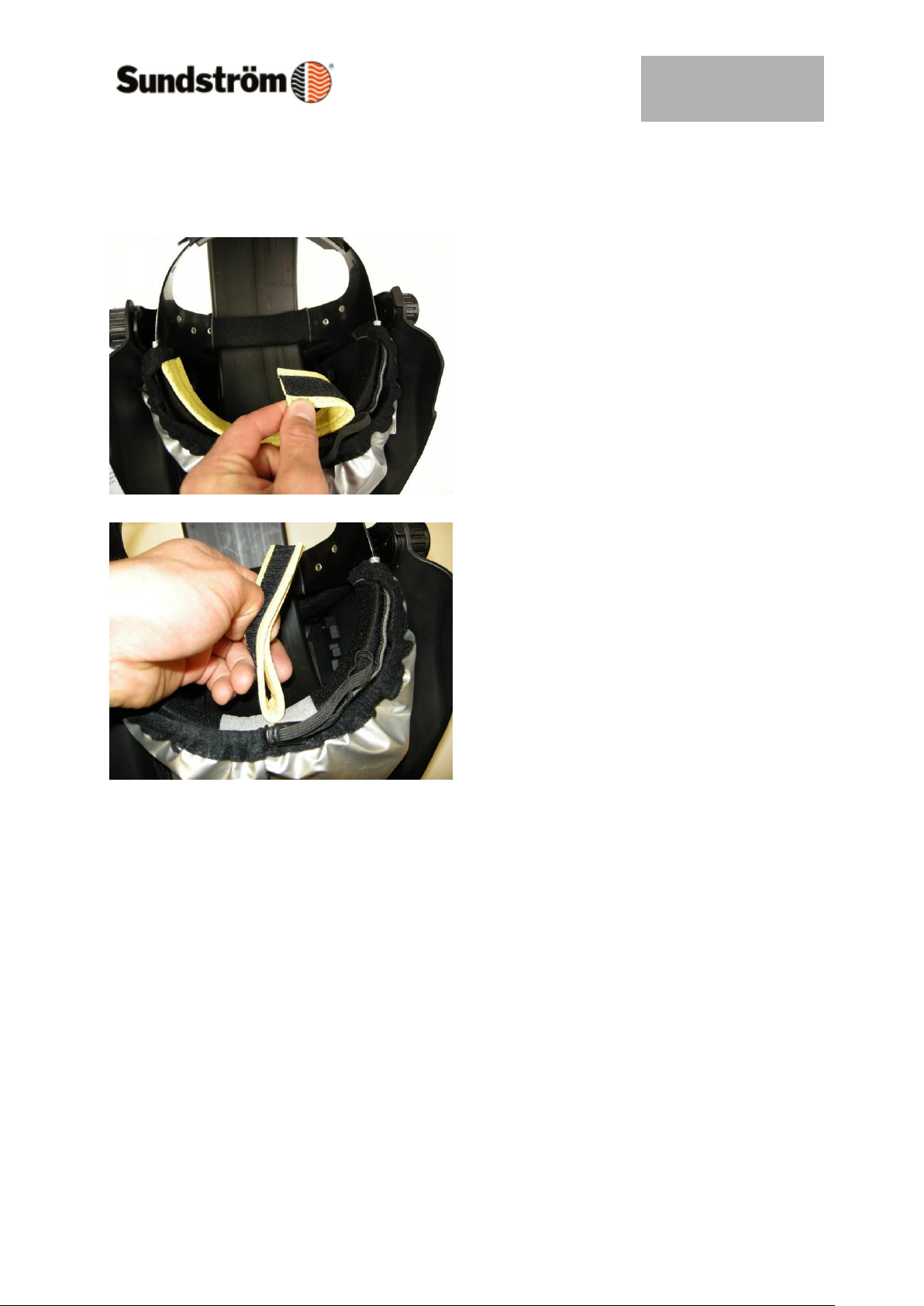
6.6 Changing the sweatband
Carefully pull the old sweatband off the
Velcro tape.
Fit the new sweatband, starting from the
centre.
Page 17
Drawn up by:
2009-02-03 / RK
OI06H-4018 SR 590
Revision:
01
Reviewed:
Page:
17 of 22
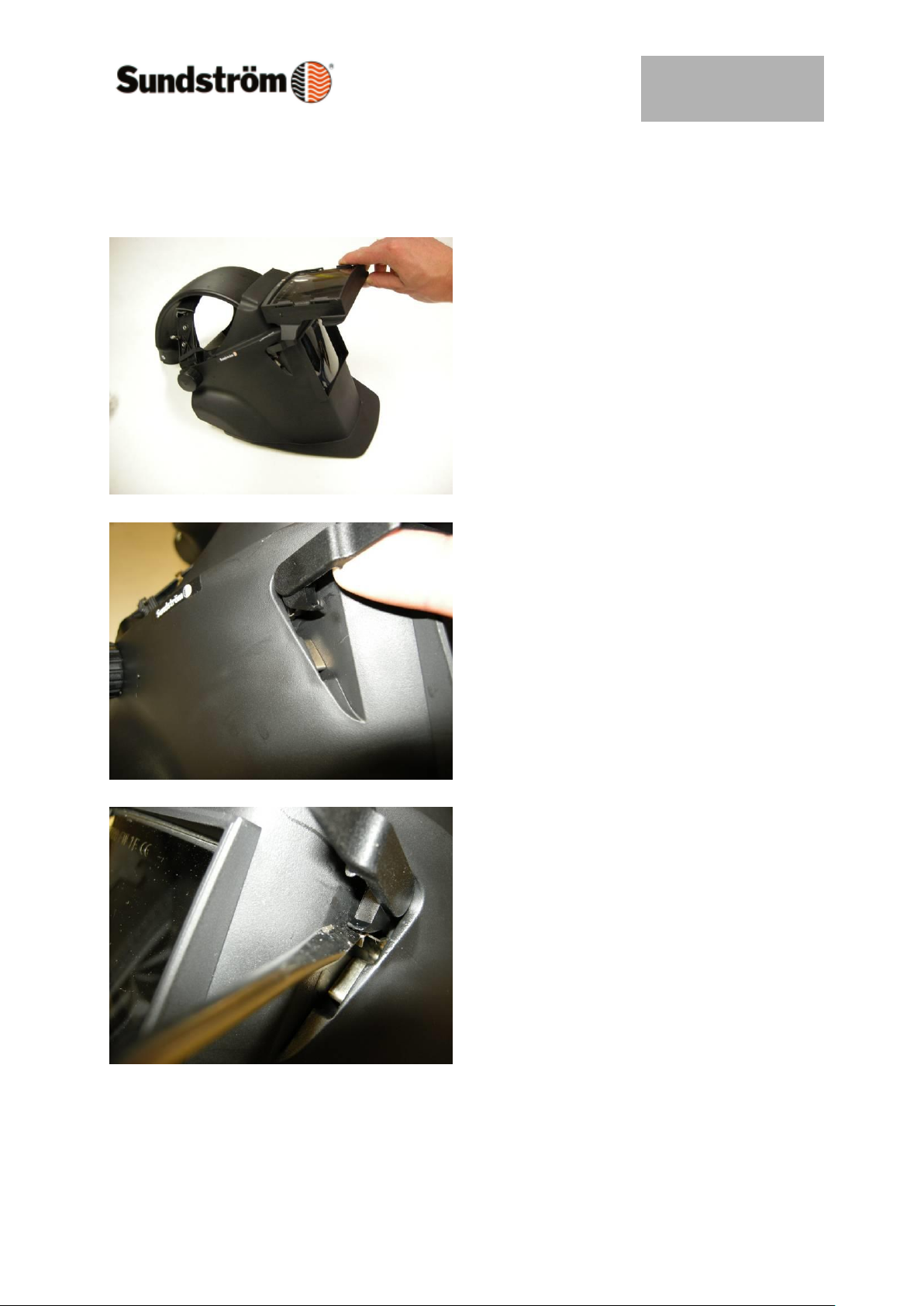
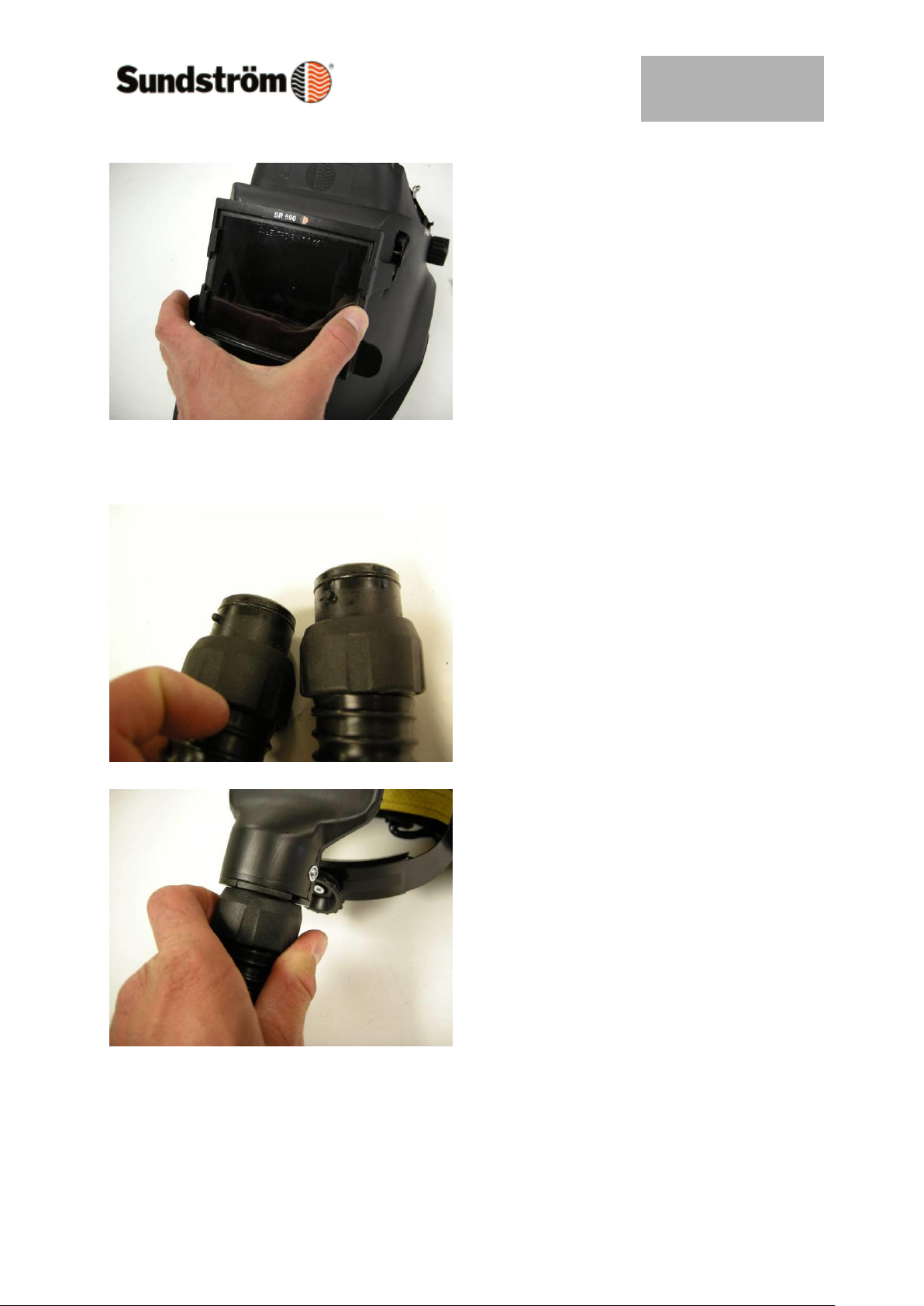
6.7 Changing the welding lens flap
Raise the flap
Press the arms of the flap out of their
mountings, one at a time. Use your
fingers or a screwdriver.
Hold the new flap at right angles to the
shield.
Insert one of the arms through the hole
in the shield, at the same time
moving away the metal spring in the
hinge of the shield, using a screwdriver.
Repeat the procedure on the other side.
Page 18
Drawn up by:
2009-02-03 / RK
OI06H-4018 SR 590
Revision:
01
Reviewed:
Page:
18 of 22
Fit the welding lens and the protective
lens.
6.8 Changing the breathing hose
Check that the O-rings of the hose are in
place.
Connect the hose and turn it clockwise
about 1/8 of a turn.
Check that the hose is firmly secured.
Page 19
Drawn up by:
2009-02-03 / RK
OI06H-4018 SR 590
Revision:
01
Reviewed:
Page:
19 of 22
6.9 Changing the head harness
Release the two side knobs. Save the
mounting parts (knob/screw/washer*)
Release the rubber bands of the face
seal from the side arms of the head
harness
Fit the new head harness, but before
screwing it in position,
secure the rubber band around the side
arms of the head
harness.
Page 20
Drawn up by:
2009-02-03 / RK
OI06H-4018 SR 590
Revision:
01
Reviewed:
Page:
20 of 22
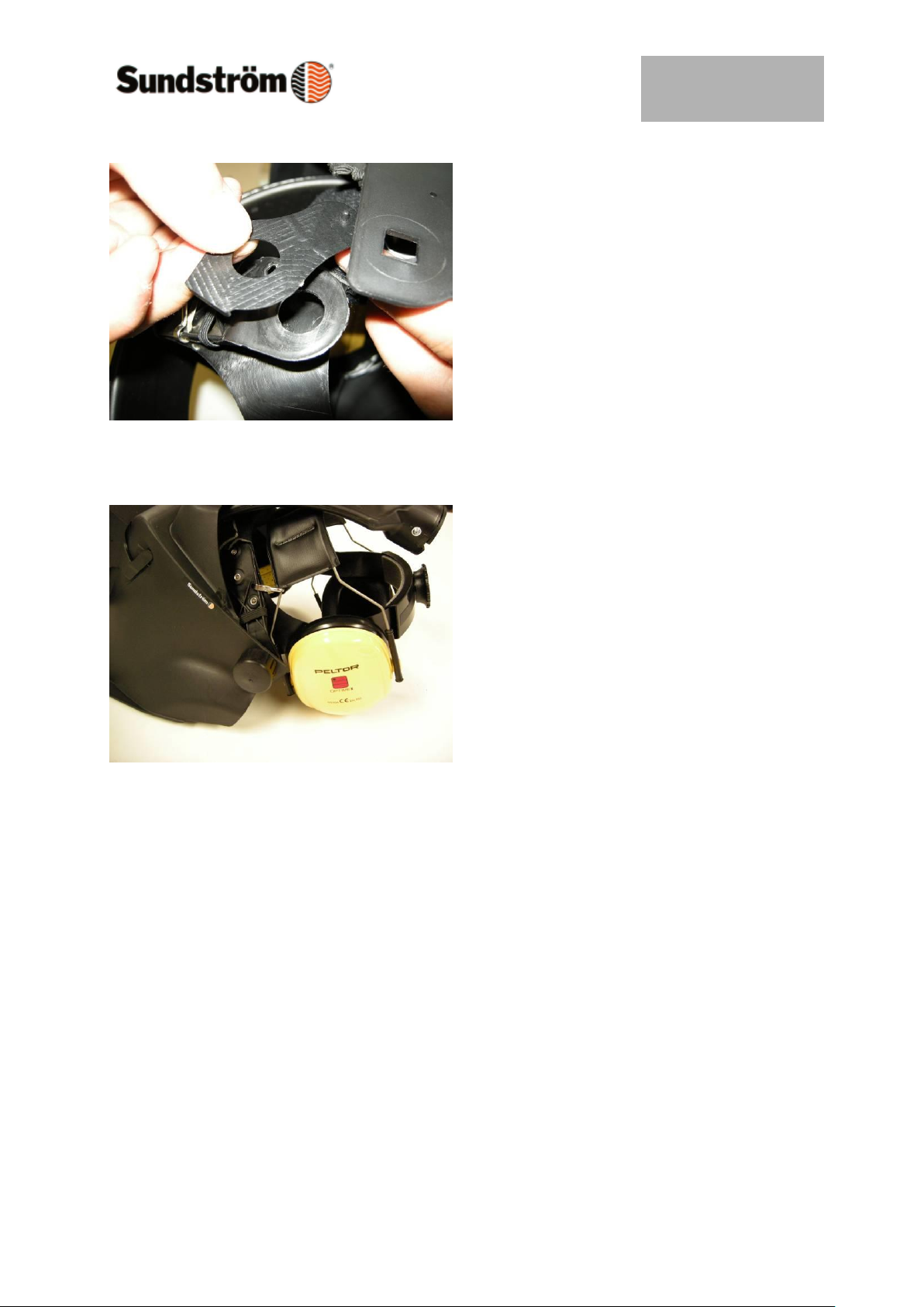
Secure the head harness. Ensure that
the pin in the special washer* fits into the
hole in the front piece.
6.10 Fitting the ear protectors
The ear protectors must be of yoke type,
e.g. Peltors Optime, H4, Alert or FM
Radio.
The ear protectors are worn on the
outside of the head harness but under
the air passage.
The front yoke of the ear protectors is
hooked onto the spring hooks on the
head harness.
Page 21
Drawn up by:
2009-02-03 / RK
OI06H-4018 SR 590
Revision:
01
Reviewed:
Page:
21 of 22
Page 22
Drawn up by:
2009-02-03 / RK
OI06H-4018 SR 590
Revision:
01
Reviewed:
Page:
22 of 22
 Loading...