

Sundrax Electronics SPSD-3-2D5D-AC, SPSD-5-2D5D-AC, SPSD-3-2D5D-DC, SPSD-5-2D5D-DC User Manual
Page 1
Version 1.03
January 17, 2017
User manual
DMX
Splitter Solid Duo
SPSD-3-2D5D-AC, SPSD-5-2D5D-AC,
SPSD-3-2D5D-DC, SPSD-5-2D5D-DC
Page 2

Table of contents
Visual appearance
Specifications
Safe operation
General information
Installation
Technical maintenance
Connection scheme
1
1
2
2
3
3
4
Page 3
1
Supported protocols DMX512, RDM
DMX data refresh rate 44 Hz
DMX input ports 1 or 2 isolated
DMX output ports 4 or 5 isolated
DMX connectors 15EDGVC terminal blocks
Mounting Surface, Truss
Setup Onboard button
Power supply
~90-250 VAC, 50/60 Hz or 12/24V
Mains Fuse 0.5 A (VAC modification)
Operating Temperature: 0°С... +60°С
IP Rating IP 44
Dimensions, mm 171(D) x 55(H) x 121(W)
Visual appearance
Specifications
4
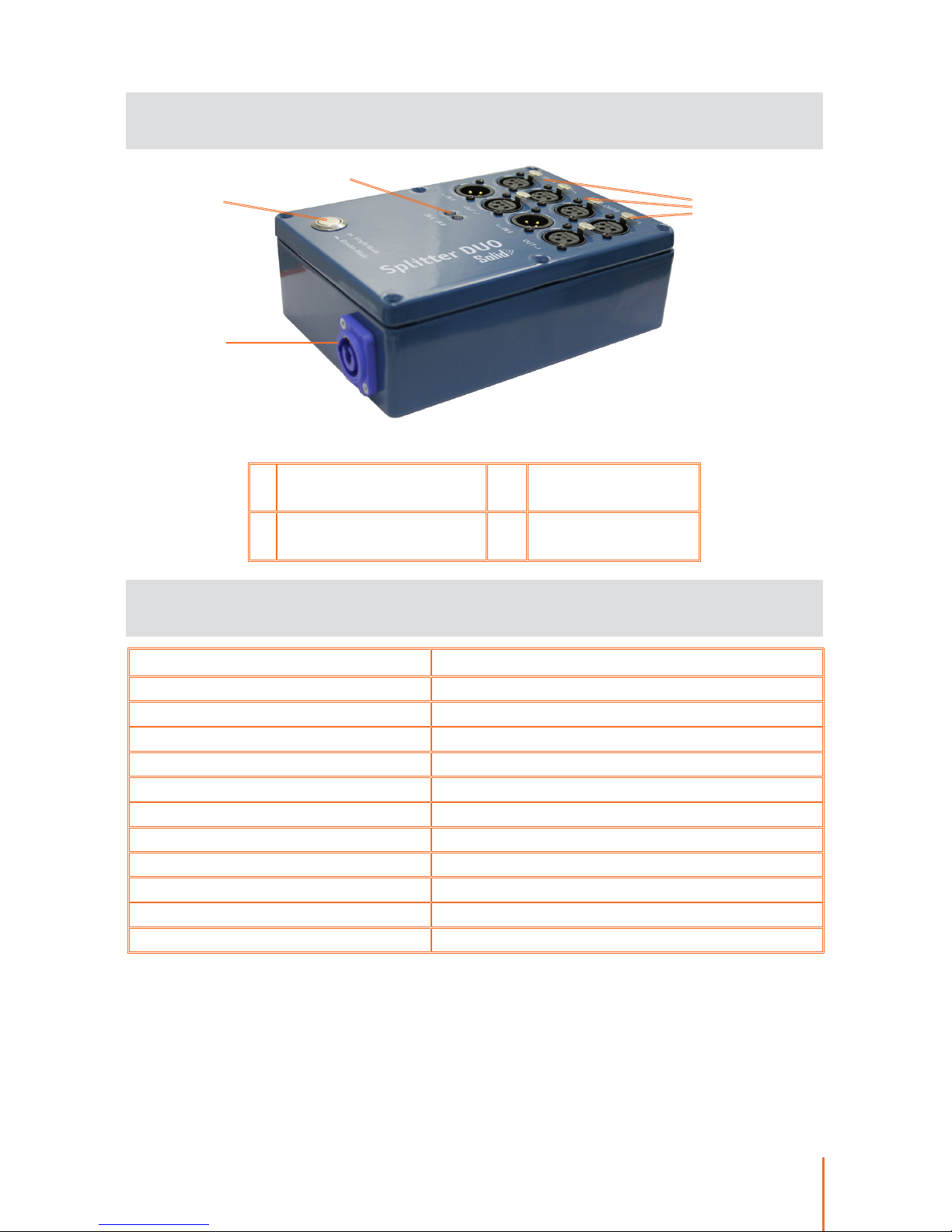
1 Mode switch button 3
DMX input and
output ports
2 LED indicators 4
Powering connector
(PowerCON)
1
3
2
Pic.1 Interfaces and connectors
Page 4
2
Safe operation
WARNING!
The device uses hazardous voltage AC 230 V
In installation, operation, preventive maintenance and repairs of
the device, the requirements of the safety rules must be followed.
To ensure safe and reliable operation of the devices, please ob-
serve the following requirements:
• Use the device only for its intended purpose;
• Do not use devices that shows signs of malfunctioning;
• Avoid strong physical impacts on the device;
• Protect devices and cables from contact with corrosive liquids.
Whenever a fault is detected in the device, please contact the
manufacturer.
General information
Splitter Solid DUO is special device with 2 DMX inputs and 4
DMX outputs that operates as a regular splitter with 1 input and 5
outputs as well as two separated 1-to-2 splitters.
All input and output channels have full galvanic isolation. Remote
Device Management (RDM) compatible. The device is suitable for
indoor use.
Key features:
• XLR connectors
• Time-tested in severe weather conditions
• Single or double input modes
Page 5

3
Installation
Before mounting and power up, it is necessary to verify protec-
tive earthing and cable connections.
Technical maintenance
Maintenance the device, search and troubleshooting should be
performed by service personnel. The device should be free from
dirt, dents, connecting cables and wires must be intact and securely
fastened.
1. Ensure the device has no damage due to transportation.
2. Install the unit onto the truss or surface. Connect the power
cable plug to a power outlet PowerCON.
3. For single-channel mode connect cable to input port «IN» (IN
A or IN B). If the input signal is present, the appropriate port indicator is green. If there is no signal, the indicator is red.
4. For dual-channel mode connect two cables to input ports
«IN» (IN A and IN B). If the input signal is present, the appropriate
port indicator is green. If there is no signal, the indicator is red.
5. Connect the desired number of output lines to the connectors
«OUT».
6. The device is ready for use.
Page 6
4
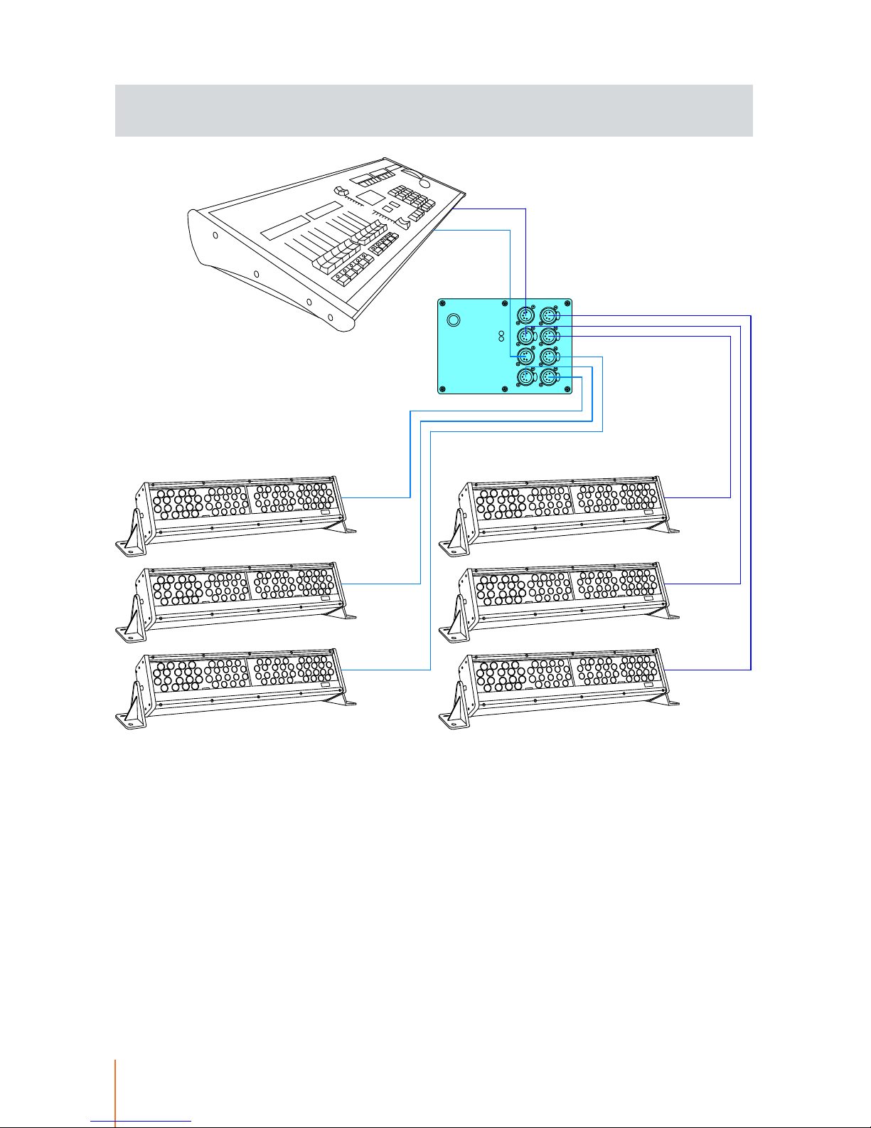
Connection scheme
IN/IN A
OUT/OUT B
OUT
IN/IN B
OUT/OUT B
OUT/OUT A
OUT/OUT A
OUT
Page 7

Please send all your warranty-related questions to
All Sundrax products are covered by a 36 months warranty.
Page 8
Sundrax Electronics,
6008, First Central 200
2 Lakeside Drive, Park Royal, London
NW10 7FQ United Kingdom
+ 44 (0) 208 991 33 19
[email protected]
www.sundrax.com
 Loading...