

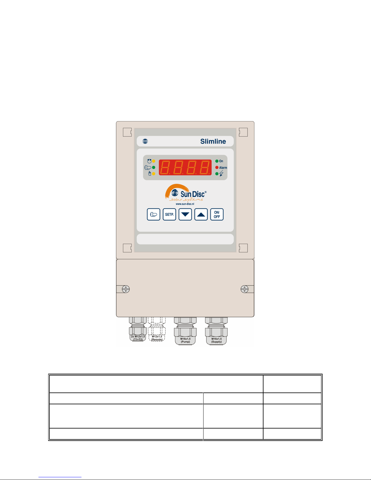
Description : Slimline, thermostat for swimming pool heating.
Wall mounting, terminals below.
Doc. no.: 081215
Type: INSTALLATION INSTRUCTIONS Number of pages: 10 Version: V1.2
File: Do081215 Slimline v1.2 EN.wpd
Software: MC385 SunDisc Slimline Version:
V2.05
By: HN Date: 31-10-2011
VDH Products BV - Roden - Holland Initials: File: Doc'07
SunDisc® Solar Systems BV
Slimline
wall mounting
Installation instructions/user manual

Installation instructions Document no. : 081215 Version : V1.2
Slimline Client : SunDisc® Solar Systems BV Page : 2 of 10
Utmost care has been taken to ensure the soundness and accuracy of the information contained in this document. VDH
Products BV will not accept any form of liability for any errors or inaccuracies and it reserves the right to amend the
contents without prior notice.
Contents
1. Technical specifications ........................................................3
2. Functional specifications .......................................................4
2.1 Working action ..........................................................4
2.2 Installation. .............................................................4
3. Operation ...................................................................5
3.1 Control elements. ........................................................5
3.2 Switching the controller on/off. ..............................................5
3.3 Viewing the temperatures. .................................................5
3.4 Viewing and/or changing the setpoint (= maximum set pool temperature). ...........5
3.5 Operating the pump control. ...............................................6
4. Programming internal settings ...................................................7
4.1 Parameter table. ........................................................7
5. Operating principle ............................................................8
6. Sensor calibration ............................................................8
7. Alarms .....................................................................9
8. Dimensions .................................................................9
9. Connections diagram .........................................................10
Installation instructions Document no. : 081215 Version : V1.2
Slimline Client : SunDisc® Solar Systems BV Page : 3 of 10
1. Technical specifications
General
Type : Slimline (MC 385)
Housing : Grey plastic
Connections : Terminals underneath
Material : ABS
Dimensions : 131 x 185 x 92,5 mm (whd)
Front : Polycarbonate
Range : 0/+100°C per 0,1°C
Power supply : 230 Vac; 50/60 Hz (-10/+5%).
Consumption : 9 VA (Electronics, so excluding pump capacity)
Internal fuse : Glass fuse 5 x 20 mm, 315mAT (slow) for electronics (excl. pump)
Operating temperature : -20/+50°C
Store temperature : -20/+60°C
Operating rel. humidity : 10/+90 % RH non condensing
Accuracy : ± 0,5 % van het bereik
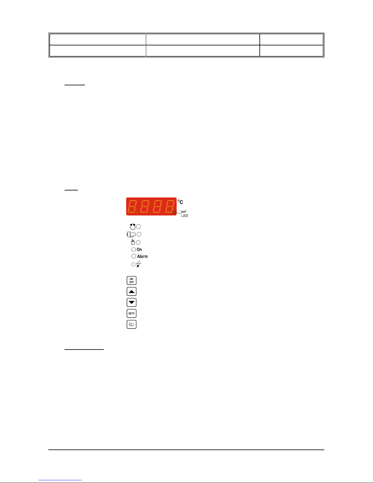
Front
Display : 4-digit digital display for temperature readout
LED's : = LED pump mode automatic
= LED pump active
= LED pump mode manual
= LED controller on
= LED alarm
= LED power supply on controller indication
Buttons : = Controller on/off button
= Up button
= Down button
= Setpoint button
= Pump mode button
In- and Outputs
Sensors : T1 Pool sensor (SM811-1) On terminal 1(bn), 3(wh) and shield on PE
T2 Collector sensor (SM 811-2) On terminal 2(bn), 3(wh) and shield on PE
Remote Display : RS485-Network 4-wireshielded cable min. 0,5mm2, max. length 1KM
Wire colors: Green on terminal 7(0V) , Brown on terminal 8(Line-A),
White on terminal 9(Line-B) and shield (gn/ye) on PE
Ext.supply: 12Vdc min. 500mA external connected
Yellow on +12V and Green on 0V (-)
SunDisc® Pump : Pump 230Vac, max. 1,5KW On terminal P1(L), P2(N) and shield on PE
Power supply : 230Vac 50/60Hz On terminal L(ive), N(eutral) and earth on PE

Installation instructions Document no. : 081215 Version : V1.2
Slimline Client : SunDisc® Solar Systems BV Page : 4 of 10
2. Functional specifications
2.1 Working action
The Slimline is a complete SunDisc® Pump Controller for heating swimming pools by means of
solar energy. The controller measures the swimming pool temperature and the collector
temperature. As soon as the collector temperature is suitable to heat the swimming the
controller starts the SunDisc® Pump to circulate the heated water.
As the pump is started on bases of the delta temperature (delta-T) than it will be active for at
least 3 minutes.
The controller checks also every 24 hours, from the time that the power supply has been
connected, if the pump has been active in this period of 24 hours.
Is this not the case than the pump will be activated to prevent long water stagnation in the
ducts. The duration of the pump circulation can be adjusted in the internal parameter P50.
If one of the temperature sensors is defective than this is been indicated by an error code in the
display.
Optionally a SunDisc® Remote Display can by connected to the controller. On this Remote
Display the pool temperature is shown and the status of the SunDisc® pump.
2.2 Installation.
On the connection diagram for the Slimline specifies how the power supply, the pump, the
sensors and an optional Remote Display have to be connected.
Make sure that the controller can be disconnected from the power supply, by a maintenance
switch or by connecting the power supply of the controller by a cable with a plug for an wall
outlet.
Use ferrules preferably not soldered on the cable ends. Think of the right wire diameters.
Connect the cable shielding of cables only on one side to the PE (= earth)!
For the shielding of the temperature sensors use the PE terminal between terminals 2 and 3.
The RS485-network is shielded on terminal PE between terminals 4 and 7. The pump cable and
power supply cable shield is connected on terminal PE between terminal P2 and terminal N.
The power supply should be sufficient fused for the pump and controller.
If the shield of a cable is laid on both sides to the earth, huge currents can be inducted which
can cause damage. If indeed the shield on both sides of the cable is connected to earth, a
compensation wire between these two ground points must be made with a minimum wire
diameter of 4mm2.
Never place the sensor and network cables in the same cable duct as the heavy current cables.
This causes failures and may eventually damage the controller.

Installation instructions Document no. : 081215 Version : V1.2
Slimline Client : SunDisc® Solar Systems BV Page : 5 of 10
3. Operation
As long as the power supply is connected to the controller the LED power on controller is lit.
After activating the controller it will show, within several seconds, the measured pool
temperature (Sensor-1) in the display.
3.1 Control elements.
The Slimline can be operated via 5 buttons on the front panel. These buttons are:
ON/OFF - To switch the controller on/off, indicated by the On LED.
UP - To increase the set value / readout the collector temperature.
DOWN - To decrease the set value / readout the delta temperature.
SETP. - To view / change the set value / reset the alarm.
PUMP - Pomp-mode selection button.
3.2 Switching the controller on/off.
The controller is switched on/off by pressing the ON/OFF button. When the controller is on
the ‘On’ LED lights up at the right-hand top of the display and the measured pool
temperature (Sensor-1) appears in the display.
3.3 Viewing the temperatures.
The pool temperature of sensor-1 is normally shown in the display.
Sun collector temperature:
Press the UP button. The measured temperature of sensor-2 (sun collector
temperature) will now be shown on the display for approximately 1 minute.
Delta temperature:
By pressing the DOWN button the delta temperature (= temperature difference
between the sun collector temperature and the pool temperature) appears in the
display for approximately 1 minute.
By pressing any key the pool temperature of sensor-1 (= normal display mode) will reappear
immediately in the display.
3.4 Viewing and/or changing the setpoint (= maximum set pool temperature).
When the SETP. button is pressed, the setpoint (maximum set pool temperature) is shown in
the display. The ‘set’ LED will also starting flashing.
Release the SETP. button.
The setpoint can now be changed by now pressing the SETP. button simultaneously with the
UP or DOWN button. A few seconds after the SETP. has been released, the setpoint
disappears and the measured temperature is visible again. The new setting will be saved.
The standard setpoint setting is 32C and is adjustable between 0C to 32C. The limits can
be modified by the dealer by means of internal parameters.

Installation instructions Document no. : 081215 Version : V1.2
Slimline Client : SunDisc® Solar Systems BV Page : 6 of 10
3.5 Operating the pump control.
The PUMP button is used for switching between pump modi.
The following pump modes are possible;
- Pump manually OFF, the LED flashes and the pump is switched off continuously.
- Pump manually ON, the LED is on and the pump is switched on continuously.
- Pump in automatic mode, the LED is on and the pump is switched on if there is a
positieve yield or during rinsing (if the pump has not been running for 24 hours).
The pump set mode is stored.
After power failure to the controller is always the last chosen mode pump.
After switching on the controller via the ON/OFF button to the controller in manual mode off.

Installation instructions Document no. : 081215 Version : V1.2
Slimline Client : SunDisc® Solar Systems BV Page : 7 of 10
4. Programming internal settings
In addition to the setpoint adjustment, there are also a number of internal settings such as the
differences, sensor offsets, setpoint range and pump settings.
These internal parameters may only be changed by SunDisc® or the SunDisc® Dealer in order to
guarantee the proper operation of the system. Only a few of these settings can be changed by the
user.
Holding down the DOWN button longer than 10 seconds will give access to the 'internal programming
menu'. For access to anything other than the user parameters, the access code first has to be entered.
This can be done by pressing the PUMP button. A digit appears at the position that can be changed,
the other positions contain a hyphen. Enter the desired digit via the UP and DOWN buttons. After the
SETP. button has been pressed, the next digit can be entered. The parameter menu will be accessible
when all digits have been correctly entered. Once entered correctly, the code will remain active for five
minutes after leaving the parameter menu.
Once in the parameter menu, three horizontal segments will flash in the left-hand display and the
parameter number will appear behind these. The desired parameter can now be selected (see
parameter table) via the UP and DOWN buttons.
When the desired parameter has been selected, the parameter value can be read by pressing the
SETP. button. To change the value, the SETP. button must be pressed simultaneously with the UP
and/or DOWN button.
If, after 20 seconds, no button is pressed, the Sundisc® Slimline will return to its normal operating
mode.
4.1 Parameter table.
PARAMETER
PARAMETER DESCRIPTION RANGE UNIT U D S DEFAULT
VALUE
01
02
03
Offset temperature sensor-1 (Pool)
Offset temperature sensor-2 (Collector)
Alarm delay E2, at measured value
below 0C
-15.0..+15.0
-15.0..+15.0
0..99
C
C
hours
N
N
Y
Y
Y
Y
Y
Y
Y
Y
0.0
0.0
0
10
11
Delta temperature heating setting
Differential heating setting
0.0..+10.0
0.1..+10.0
C
C
NNNNY
Y
-
-
20
21
Minimum adjustable setpoint
Maximum adjustable setpoint
0.0..100.0
0.0..100.0
C
C
NNYYY
Y
0.0
32.0
30 Readout in hole degrees 0=no, 1=yes 0..1 - Y Y Y 0
50 Length of time rinsing 1..60 minutes N Y Y 15
60 password 1(installer) 0000..9999 - N N Y 97
98
99
Software version *
Serial number *
Production date *
-
-
-
--
-
year/week
Y
Y
Y
Y
Y
Y
Y
Y
Y
-
-
-
U= User, D=Dealer (Installer), S=SunDisc® employee,
N=not authorised to read and/or change, Y=yes authorised to readout and/or change,
*) = Read only, can not be changed.

Installation instructions Document no. : 081215 Version : V1.2
Slimline Client : SunDisc® Solar Systems BV Page : 8 of 10
5. Operating principle
6. Sensor calibration
The temperature sensors for the pool and collector are calibrated ex factory and the deviation is
specified on a label on each individual temperature sensor. To put to use, both sensor deviations only
have to be set on the regulator by the Dealer if this has not already been done by SunDisc®.
The offset for the collector sensor (T1) must be corrected under parameter 01.
The offset for the collector sensor (T2) must be corrected under parameter 02.
If, for example, the label on the pool temperature sensor specifies the value 0.9, then this means that
this temperature indicates 0.9C too low in relation to the gauge temperature of 22C. The value that
then has to be entered under parameter 01 is 0.9 (positive). If the value on the label reads +2.0, then
the value of -2.0 has to be entered under the relevant parameter.
Example: If a temperature sensor has to be replaced by a new sensor then the Dealer or SunDisc
®
employee has to enter the specified deviation (e.g. -0.5C) as a negative value
(-(-0.5C))=+0.5C in the corresponding offset temperature sensor parameter (02 for the
collector and 01 for the pool sensor), irrespective of the value that was already there.
N.B. 90% of the sensor calibrations are performed by SunDisc®. De a l ers should only perfo r m
calibrations if they have regulators in stock and a different cable length supplied by SunDisc®.

Installation instructions Document no. : 081215 Version : V1.2
Slimline Client : SunDisc® Solar Systems BV Page : 9 of 10
7. Alarms
Error messages.
The following error messages may appear in the Slimline display:
Code Alarm Action
E1 Pool temperature
sensor defect
The pump is turned off in automatic pump operation mode, only
manual pump operation is still possible.
E2 Collector temperature
sensor defect or
longer than parm. 03
hours below 0C
The pump is turned off in automatic pump operation mode, only
manual pump operation is still possible.
Solution for E2: - Adjust Alarm delay time of internal parameter P03.
Solution for E1 and/or E2: - Check that the relevant sensor is properly connected.
- Check the relevant sensor (1000 at 25C).
- Replace the relevant sensor.
When error messages E1 and E2 occur, the alarm LED also flashes.
The alarm LED also flashes when the pump is operating in manual mode.
Reset alarm: The alarm can be reset via the SETP. button.
8. Dimensions
Housing dimensions

Installation instructions Document no. : 081215 Version : V1.2
Slimline Client : SunDisc® Solar Systems BV Page : 10 of 10
9. Connections diagram
Connections of the SLIMLINE wall mounting model drawing 072421w6
-.-.-.-.-.-.-.-.-.-
 Loading...