

Sundez SDWW-100, SDWW-160-S, SDWW-260-S, SDWW-320-S, SDWW-500-S Installation Instructions Manual
...
SUNDEZ
Ground source Heat Pump
Heating/Cooling Series
(Heating only Series)
Installation&Instruction Manual
(Brine/water)

- 1 -
Content
Ⅰ
.SUNDEZ ground source heat pump introduction
1. Characteristics.....................................................................................2
2. Model number nomenclature..............................................................3
3. Performance parameter table...............................................................4
4. Dimension and conformation.............................................................5
5. Electrical diagram................................................................................8
Ⅱ. Installation..............................................................................................11
1. Transport and position......................................................................11
2. Pipeline installation system notice....................................................12
3. Installation of the heat source system.............................................12
4. Installation of the heat consumer system........................................13
5. Electrical connection.........................................................................14
6. Commissioning..................................................................................15
7. Maintenance and cleaning...............................................................16
8. Water quality standards...................................................................16
9. Using monoethylene glycol..............................................................18
Ⅲ. Operation of controller..........................................................................19
1. User interface.....................................................................................19
2. Operation...........................................................................................19
3. Usual malfunctions............................................................................24
Ⅳ
.Maintenance information.........................................................................26
Ⅴ
.System planning.....................................................................................27
1. Basic knowledge...............................................................................28
2. System planning................................................................................30
INSTAL LATION & INS TRUCTIO N MA NUAL

- 2 -
Ⅰ.Introduction on SUNDEZ ground source heat pump
1. Characteristics
●
●
High quality construction
Quiet operation
Sundez ground source heat pump is a heating system designed for operation as
brine/water or water/water heat pump. The heat pump extracts energy from the heat
source medium i.e. brine at a low temperature level. This extracted energy is then
transferred to the heating water at a higher level, enriched with the energy
transferred by the compressor. The underground heat can be transferred through
the horizontal or vertical underground loop system. The heating water can be heated
up to a flow temperature of 55 .℃
Cabinet--Standard unit fabrication consists of heavy gage galvanized sheet metal
cabinet construction that provides maximum strength. All exterior sheet metal
surfaces are powder-coated for maximum corrosion protection to ensure resilience
for long term vitality. Compact, stackable cabinets are designed to minimize
installation space.
Compressor--Standard high-efficiency scroll compressor design for all units.
Compressor isolating springs are specially selected for each compressor size.
Refrigerant/water circuit--Units have a sealed refrigerant circuit including scroll
compressor(S). Refrigerant circuits are provided with a standard thermostatic
expansion valve(TEV) for higher accuracy and performance. The condenser and
evaporator are brazed stainless steel SUS316# plate heat exchangers with the
highest heat exchanging efficiency, outstanding ability against high pressure and
lower water quality.
The whole unit is designed for quiet operation. Compressor isolating springs are
specially selected for each compressor size. The floating design of the compressor
support with rubber isolators which completely separate the compressor from the
cabinet, to minimize vibrations to the unit structure.
●
Built-in Hydraulic module, easy installation(Optional)
Hydraulic module(flow switch, expansion tank, water pumps, 3 way solenoid valve is
built-in.
INSTAL LATION & INS TRUCTIO N MA NUAL

- 3 -
2. Model Number Nomenclature
SD WW - 160 - S
100: 10.6KW
160: 16.6KW
260: 26.6KW
Manufacturer:
Power Supply:
S: 380V/3ph/50Hz
Omit: 220V/1ph/50Hz
Type:
Heating capacity:
WW: ground source
(water to water)
SD - SUNDEZ
INSTAL LATION & INS TRUCTIO N MA NUAL
- 4 -
3
. Performance parameter table
INSTAL LATION & INS TRUCTIO N MA NUAL
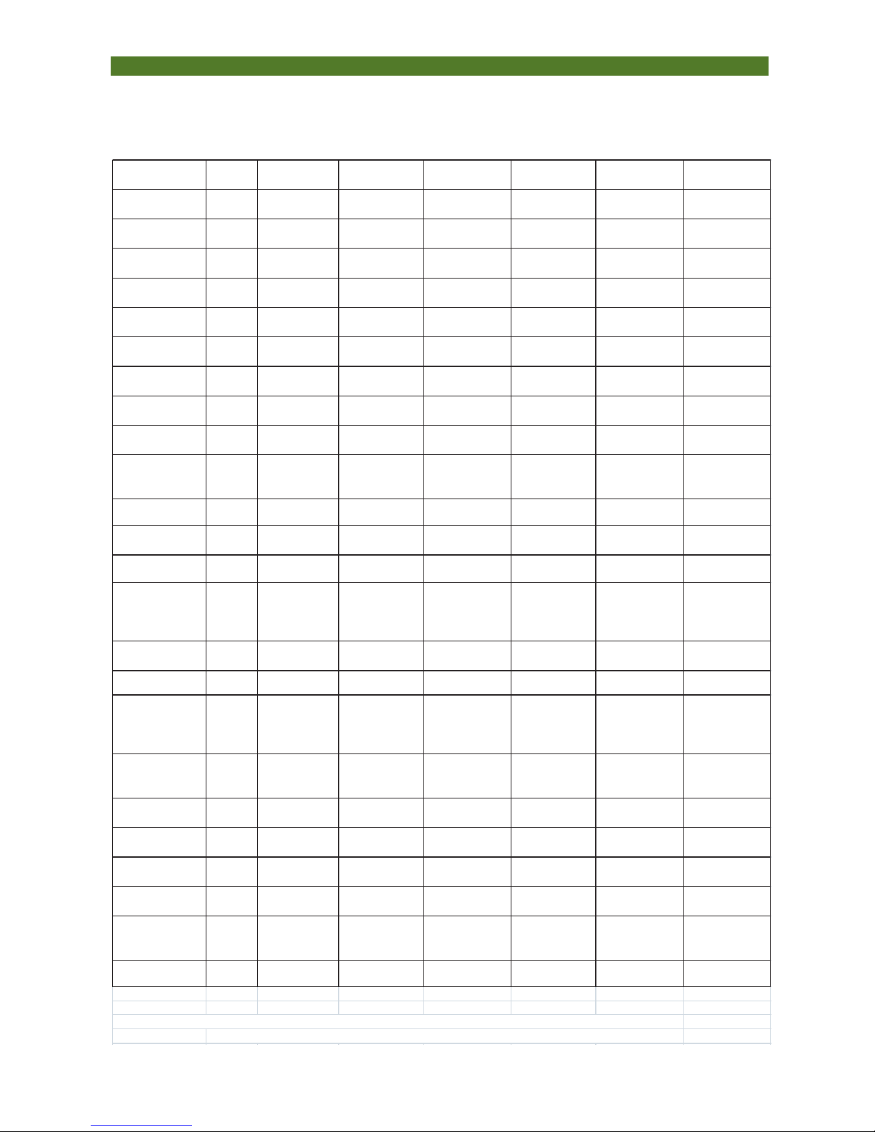
Model SDWW-100 SDWW-160-S SDWW-260-S SDWW-320-S SDWW-500-S SDWW-600-S
Power Supply V/ph/Hz 220~240/1/50 380~400/3/50 380~400/3/50 380~400/3/50 380~400/3/50 380~400/3/50
Heating Capacity
(W7/W35) KW 10.6 16.6 26.6 33.2 53.2 62.4
Heating Power
Input (W7/W35) KW 2.9 4 5.9 7.9 12 14.3
Heating Capacity
(W7/W45) KW 10.2 16 25.6 32 51 61
Heating Power
Input (W7/W45) KW 3.3 4.5 6.7 8.8 13.4 16
Cooling Capacity
(W25/W7) KW 8.1 13.8 21 27.6 42 50
Cooling Power
Input (W25/W7) KW 2.7 3.6 5.57 7 11.4 13
Water Source
Flow Ton/hour 1.4 2.4 3.8 5 7.6 10
Air Condition
Water Flow Ton/hour 1.7 2.7 4.4 5.5 8.8 11
Air Condition
Water Pressure
Drop KPa 10 10 10 15 15 15
Compressor
Style Scroll Scroll Scroll Scroll Scroll Scroll
Compressor
Quantity pc 1 1 1 1 2 2
Refrigerant R410A R410A R410A R410A R410A R410A
Air
condition/Water
Source Pipe
Connection 1-1/4"F 1-1/4"F 1-1/2"F 1-1/2"F 2"F 2"F
Recommended
Buffer Tank L 200 200 200 200 300 300
Noise Level dBA 32 34 38 40 43 45
Water Source
Inlet Water
Temp.Range(He
ating) ℃ -5 to +25 -5 to +25 -5 to +25 -5 to +25 -5 to +25 -5 to +25
Maximum Hot
Water Outlet
Temp.(Heating) ℃ 55 55 55 55 55 55
Cooling Start
Current A 65 35 55 35 55 64
Heating Start
Current A 68 41 60 41 60 69.5
Cooling Running
Current A 13 6 10.1 14.6 20.2 22.8
Heating Running
Current A 13.4 7.7 12.1 15.7 24.2 27.4
Net
Dimension(Dept
h*Width*Heigh) mm 690*620*1350 690*620*1350 690*620*1350 690*620*1350 1150*824*1204 1150*824*1204
Net Weight kg 100 130 250 280 330 350
Test condition: Cooling: W25/W7: Ground Source inlet Temp. 25℃, air condition water outlet 7℃.
Heating: W7/W35: Ground Source inlet Temp. 7℃, air condition water outlet 35℃
- 5 -
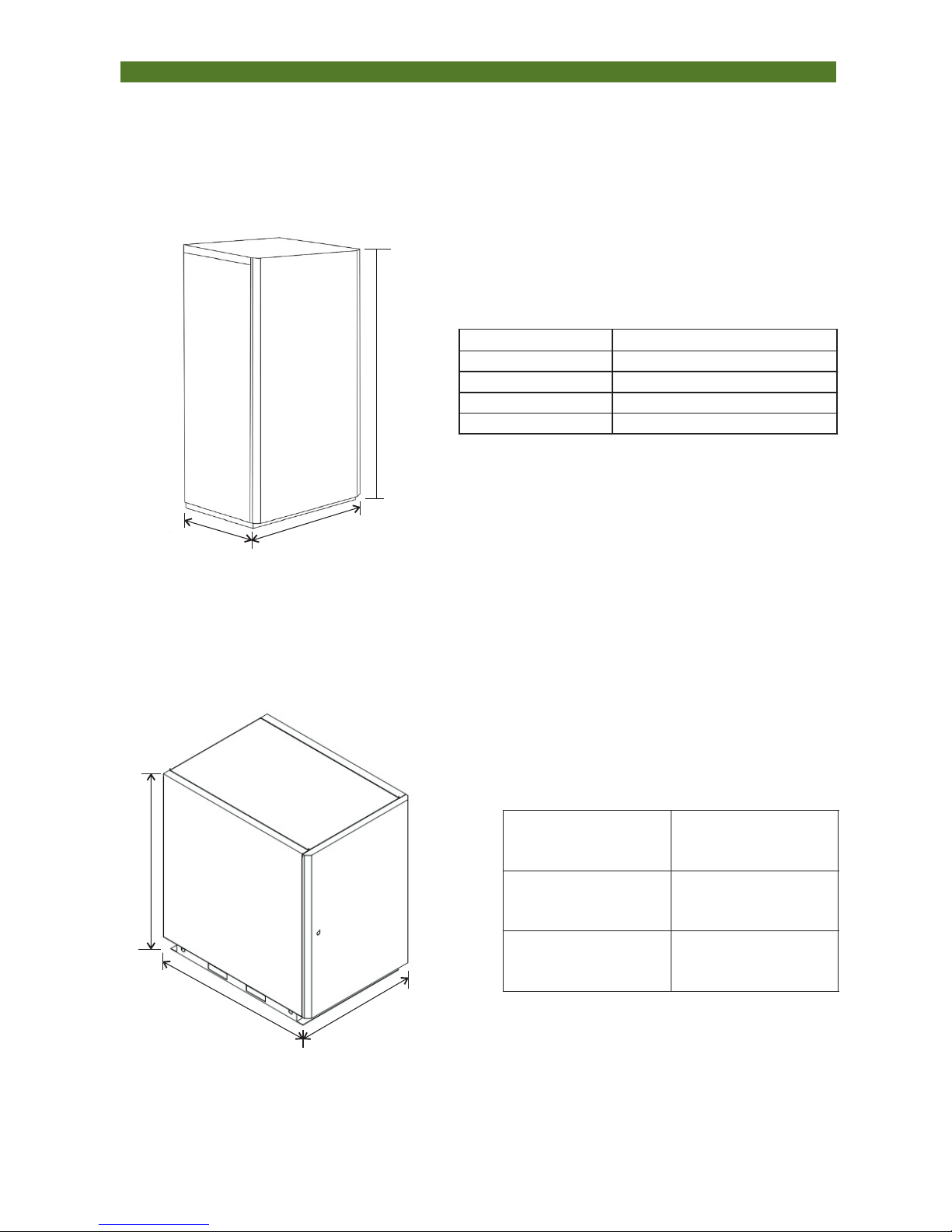
4. Dimension and Conformation
Outer Case Dimension
Left-front View
D
W
H
INSTAL LATION & INS TRUCTIO N MA NUAL
Model Dimension/D*W*H (mm)
SDWW-100-WR 703×611×1340
SDWW-160-SWR 703×611×1340
SDWW-260-SWR 703×611×1340
SDWW-320-SWR 703×611×1340
D
W
Model
Dimension/D*W*
H(mm)
SDWW-500-S
1150X824X1204
SDWW-600-S
1150X824X1204
H
- 6 -
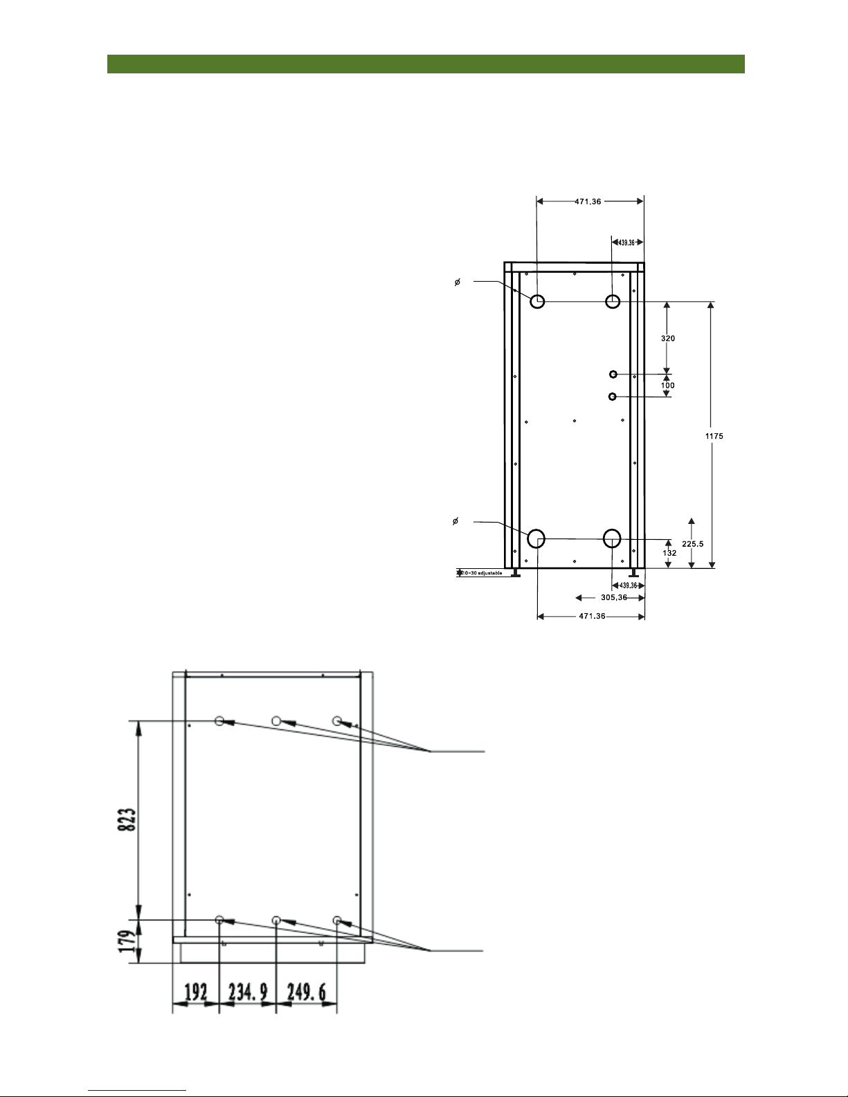
INSTAL LATION & INS TRUCTIO N MA NUAL
70
46
Back View
Model: SDWW-100
SDWW-160-S
SDWW-260-S
SDWW-320-S
Model: SDWW-500-S
SDWW-600-S
Ground source
Ground source
Hot Water
Hot Water
Air Condition
Air Condition
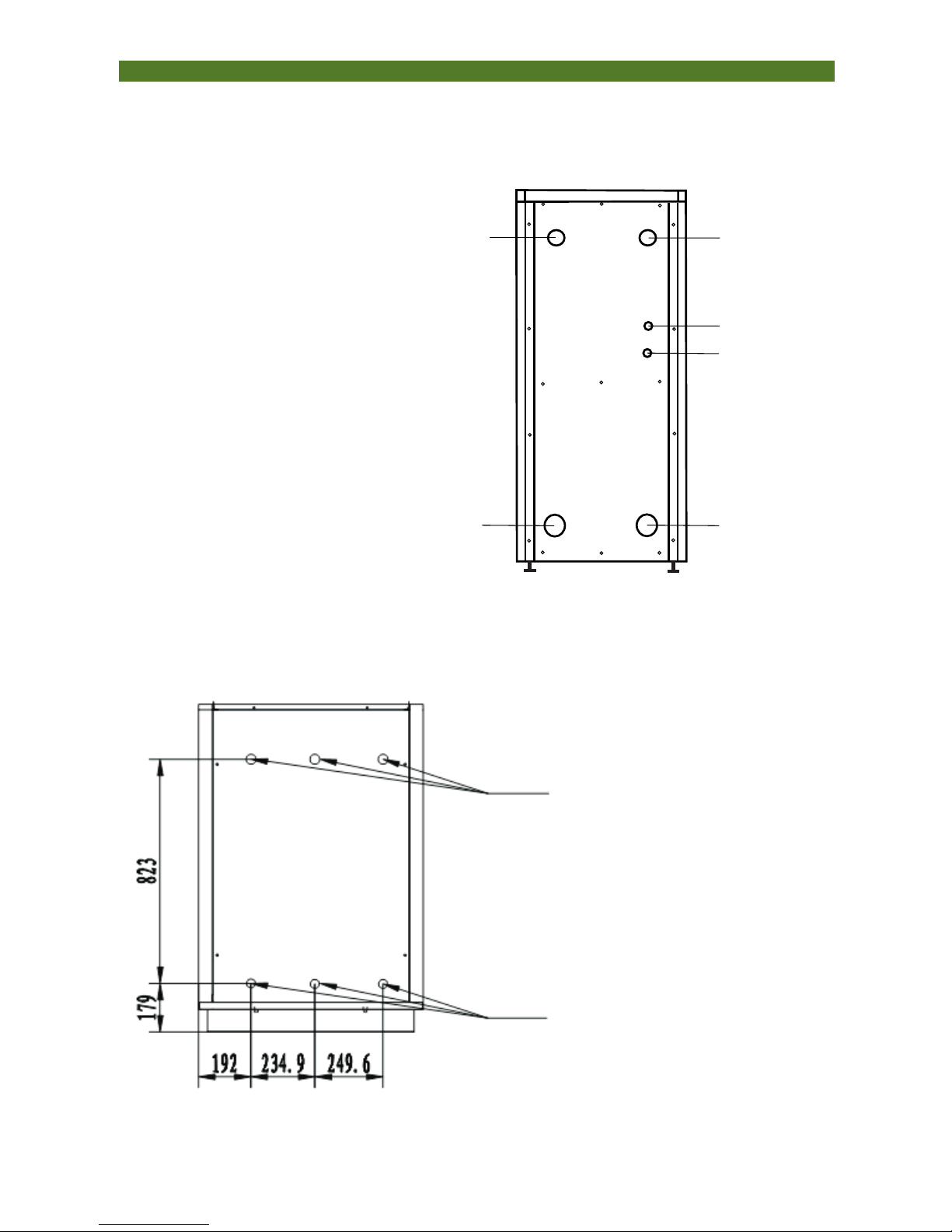
- 7 -
INSTAL LATION & INS TRUCTION MA NUAL
Air Con .wat er outl et
DN25 fe male
Air Con .wat er inle t
DN25 fe male
Groun d sourc e
outle t
Groun d sourc e in let
For wir e contr oller
For pow er cabl e
DN25 fe male
DN25 fe male
Specification of Water Connections
Model: SDWW-100
SDWW-160-S
SDWW-260-S
SDWW-320-S
Ground source
Ground source
Hot Water
Hot Water
Air Condition
Air Condition
Water Outlet
Water Inlet
Model: SDWW-500-S
SDWW-600-S
- 8 -
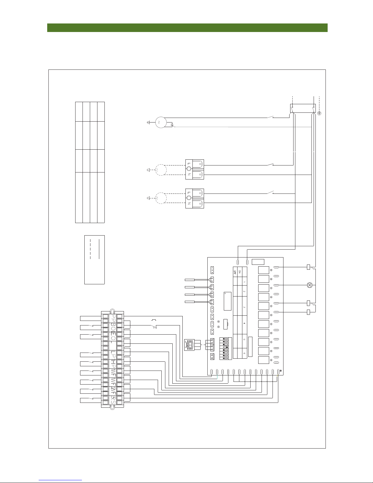
5.Electrical Diagram
INSTAL LATION & INS TRUCTIO N MA NUAL
Model: SDWW-100
CD0643MB
CONTROLLER MODEL:
AD1AD2AD3AD4AD5
12V
GND
RD
TD
5687342
ON
1
DI1
B
A
TD
RD
GND
12V
DO11
220V/50HZ)
COMP.
MCU
M
KA2
KM1
*A2
*A1 *A1
*A2
L
N
FUSE
AC220V/5A
DO10DO9 DO7DO8 DO4DO3DO5DO6 DO1DO2
DI2
DI4
DI3
DI7
DI8
DI6
DI5
DI10
DI9
DI11
DI12
RS485
AD6AD7AD8
LED1LED2
JTPG
N N N
N
L
COM
TB1
FUNCTION SET:
L
N
SIGN EXPLANATION:
KM
KA1
WIRE
CONTROLLER
MF
1/2
L
no
com
KA2
KA1-2
KA1
*A1
*A2
KM
A2
A1
no
com
MF
1/2
S
R
C
*96
COM
FR1
*95
17
TB1
YLW
TB2
TB2
GROUND
SOURCE
PUMP
AIR
CONDITION
PUMP
RED
BLU RED
BLU
BLK
RED
WHI
BLU
COMP.1
4 way valve
ground source
pump
air condition
pump
BLU
BLU
BLU BLU
BLU
YLW
COMMON
TERMINAL
RED
BLU
DIP
double
system
single
system
all heat
recovery
part heat
recovery
electric heater
valid
electric heater
invalid
DHW valid
DHW invalid
single
speed fan
commissioning
normal work
double
speed fan
YLW
YLW
YLW
YLW YLW YLW
YLW
YLW YLW
3 PHASE PROTECTION
COMP. OVERLOAD
ELECTRIC HEATER OVERLOAD
LOW PRESSURE SWITCH
HIGH PRESSURE SWITCH
DHW FLOW SWITCH
GROUND SOURCE FLOW SWITCH
AIR CONDITION FLOW SWITCH
FAN INTERLOCK
FACTORY WIRE
USER WIRE
AIR CONSITION INLET WATER TEMP.
AIR CONSITION OUTLET WATER TEMP.
GROUND SOURCE INLET WATER TEMP.
GROUND SOURCE OUTLET WATER TEMP.
SIGN
EXPLANATION
SIGN
EXPLANATION
CONTACTOR
TERMINAL
BOARD 1
RELAY
TERMINAL BOARD 2
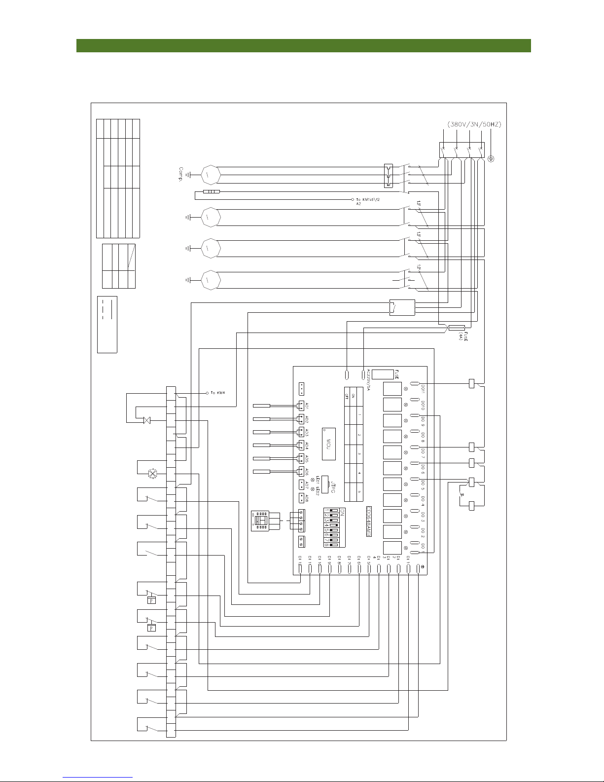
INSTAL LATION & INS TRUCTION MA NUAL
Model: SDWW-160-S
SDWW-260-S
SDWW-320-S
- 9 -
KM2
M
Ground
source
pump
Controller model:
Ground source inlet temp.
air con. inlet temp.
FR1
*22*2 *4 *6
KM1
*21*1 *3 *5
12V
GND
RD
TD
TVR
Common
terminal
B
A
TD
RD
GND
12V
phase protector
Comp. heat cable
contactor
heat relay
CCH
M
L1 L2 L3
COM ON
Explanation on signs:
Sign Explanation
KM1-4
FR1-2
TVR
CCH
fuse
FUSE
TB
terminal block
KM2
KM3
KM1
*A2
*A1 *A1
*A2 *A2
*A1
KM4
M
DHW pump
L
N
RS485
*2
*7
KT
*A2
*A1
*8 *6
KM4
N N N N N
L
N
L
1 2 3 4 5
COM
6
7
8
9
10
11
12
14
15
14
COM
*2 *4 *6
*1 *3 *5
*2 *4 *6
*1 *3 *5
*2 *4 *6
*1 *3 *5
Yellow
Green
Red
Blue
A
QF
QF
breaker
Normal operation
mode
Debug mode
DHW disabled
heat pump
DHW enabled
Electricheater
Grade1 en abled
Cooling only
DIP switch
Function setting:
KT
time relay
KT
L1
L2
L3
N
21
Green
Brown
Blue
Red Brown Yellow
white
Yellow
Brown
Green
Yellow
Blue
Red
V
U W
Model
Sign
A(mm2)
Model table:
Wire diameter(see the model table)
A
Wire
controller
11 1312107 9863 54212 113118 10974 65321
DHW Inlet temp.
2 way valve
-A2
13
Orange
fault output
Brown
Brown
Brown
Yellow
Orange
Green
Yellow
Red
Yellow
Red
Yellow
Pressure switch-Low
Pressure switch-High
DHW flow switch
air Con. flow switch
ground source flow
switch
indoor interlock switch
Sign
Explanation
User wiring
Factory wiring
Explanation:
1."*#" is the electric components number.
Please do not mix with wire number.
2. Wire diameter not marked is 0.75 2.
KM3
Air Con.
Pump
M
4 way valve
Electricheater
Grade 1 disabled
Electricheater
Grade2 en abled
Electricheater
Grade 2 disabled
air con. outlet temp.
Ground source outlet temp.
DHW outlet temp.
thermostati switch
Air Con. auxilary heater
overload
anti-freeze switch
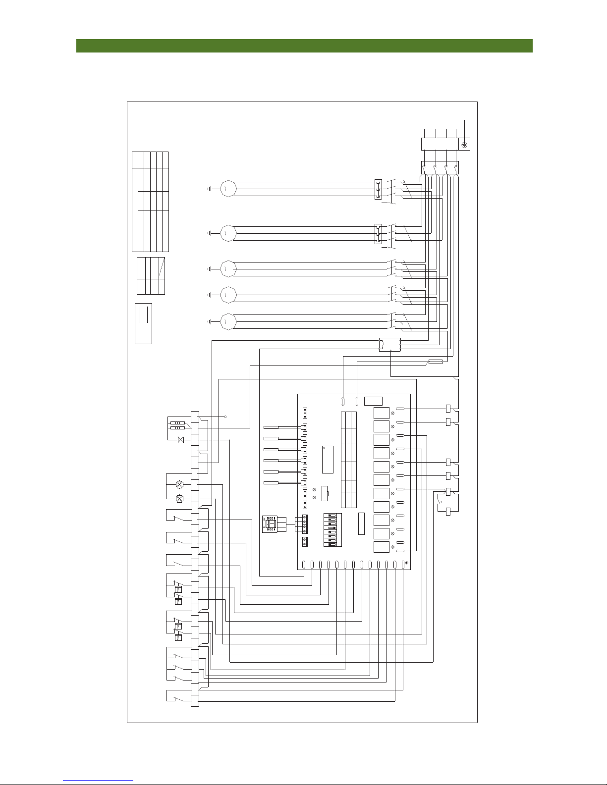
INSTAL LATION & INS TRUCTION MA NUAL
Model: SDWW-500-S
KM4
Air Con.
pump
M
KM3
M
Ground
source
pump
CD0648AMB
Controller No.:
AD1AD2AD3AD4AD5
air con. inlet temp
FR1
*22*2 *4 *6
KM2
*21*1 *3 *5
12V
GND
RD
TD
5687342
ON
1
TVR
DI1
common
terminal
BA
TD
RD
GND
12V
DO11
(380V/3N/50HZ)
phase protector
Comp. heater cable
contactor
heat relay
MCU
M
L1 L2 L3
P1 P2
explanation on signs:
sign
explanation
KM1-5
FR1-2
TVR
CCH
fuse
FUSE
Factorywiring
explanationsign
TB
terminal block
KM3
KM4KM1
*A2
*A1
(4A)
FUSE
*A1
*A2 *A2
*A1
KM5
M
DHW pump
L
N
FUSE
AC220V/5A
DO10DO9 DO7DO8 DO4DO3DO5DO6 DO1DO2
DI2
DI4
DI3
DI7
DI8
DI6
DI5
DI10
DI9
DI11
DI12
RS485
AD6AD7AD8
LED1LED2
JTPG
*14
13
KT
*A2
*A1
9 5
KM5
N N N N N
L
N
L
1 2 3 4 5
COM67
8
9
10
11
12
14
15
Explanation:
1,"*#"is the electric components number.
Please do not mix with wire number.
2,Wire diameter not marked is 0.752
COM
*2 *4 *6
*1 *3 *5
*2 *4 *6
*1 *3 *5
*2 *4 *6
*1 *3 *5
A 1.02 1.02 1.02
QF
QF
breaker
Debugmode
heat pump
DHWenabl ed
Elect ri c heater
Gr ade1enabl ed
5432
cooli ng only
1
OFF
ON
DIP swi t ch
Functi onSett i ng:
KT
time relay
KT
L1
L2
L3
N
red
brown
bl ue
red red
bl ack
yel low
bl ue
red
V
U W
Model
Sign
A(mm2)
Model table:
Wire diameter(see the model table)
A
wire
controller
11 1312107 9863 54212 113118 10974 65321
4 way valve 1
2 way valve
接KM5-A2
13
FR1
*22*2 *4 *6
KM1
*21*1 *3 *5
COMP.1
CCH
M
A
V
U W
*A2
*A1
N
KM2
16
17
red
red
bl ack
whi t e
CCH
N0
N
R
S
T
N
TB
red
red
red
yel low
yel low
yel low
yel low
yel low
yel low
yel low
yel low
yel low
yel low
red
bl ackwhit e
red
bl ackwhit e
red
bl ackwhit e
red
bl ackwhit e
Elect ri c heater
Gr ade1enabl ed
Elect ri c heater
Gr ade1enabl ed
Elect ri c heater
Gr ade1enabl ed
DHWenabl ed
Normal operati on
mode
COMP.2
air con. outlet temp
ground sourceinlettemp
ground sourceoutlet temp
DHW inlet temp
DHW outlet temp
fault output
4 way valve 2
thermostatiswitch
air con. auxiliary
heater overload
anti-freezeswitch
pressure switch-low 1
pressure switch-high 1
pressure switch-low 2
pressure switch-high 2
DHW flow switch
air con. flowswitch
ground source flow
switch
indoor interlock switch
User wiring
- 10 -
SDWW-600-S
 Loading...