

Page 1

SMT6035
User Manual
Version 2.2
User Manual - Version 2.2, 04/01/07; © Sundance Italia S.R.L.
Page 2

Version 2.2 Page 2 of 39 SMT6035 User Manual
1 Revision history
Date Comments Engineer Version
08/05/04 First rev FA 1.0
08/07/04 Minor fixes FA 2.0
26/08/05 Minor fixes FA 2.1
04/01/07 Typos fixed.
Added reference to
README.pdf
instructions file.
GM 2.2
User Manual - Version 2.2, 04/01/07; © Sundance Italia S.R.L.
Page 3

Version 2.2 Page 3 of 39 SMT6035 User Manual
2 Table of Contents
1 Revision history .............................................................................................................................. 2
2 Table of Contents ........................................................................................................................... 3
List of abbreviations................................................................................................................................. 6
3 List of figures................................................................................................................................... 6
4 Introduction ..................................................................................................................................... 7
5 Conventions.................................................................................................................................... 8
6 Prerequisites................................................................................................................................... 8
7 Software Installation and Setup...................................................................................................... 9
8 Hardware overview ......................................................................................................................... 9
8.1 Comport.................................................................................................................................. 9
8.2 The CPLD............................................................................................................................. 10
8.3 State of the IIOF lines .......................................................................................................... 10
8.4 The PCI bridge chip .............................................................................................................10
9 Software design ............................................................................................................................ 11
9.1 Interface mechanism............................................................................................................ 11
10 Functions exported by libsmtdrv.so ..............................................................................................11
10.1 SmtOpen .............................................................................................................................. 11
10.2 SmtGetBoardCount.............................................................................................................. 12
10.3 SmtOpenBoard ....................................................................................................................12
10.4 SmtCloseBoard .................................................................................................................... 12
10.5 SmtGetBoardIndex............................................................................................................... 13
10.6 SmtGetBoardInfo .................................................................................................................13
10.7 SmtGetError ......................................................................................................................... 14
10.8 SmtGetDLLVer..................................................................................................................... 14
10.9 SmtGetPluginVersion........................................................................................................... 15
11 Functional description................................................................................................................... 16
12 Host comport................................................................................................................................. 16
12.1 CpRead ................................................................................................................................ 16
12.2 CpWrite ................................................................................................................................ 17
12.3 CpCancel.............................................................................................................................. 17
13 Downloading files.......................................................................................................................... 17
13.1 BinaryLoad ........................................................................................................................... 17
13.2 CoffLoad............................................................................................................................... 18
14 Mailboxes...................................................................................................................................... 18
14.1 MbWrite................................................................................................................................ 19
14.2 MbRead................................................................................................................................ 20
14.3 MbCancel ............................................................................................................................. 20
15 High speed channel ...................................................................................................................... 20
15.1 Data transfer mechanism ..................................................................................................... 20
15.2 Control words ....................................................................................................................... 22
User Manual - Version 2.2, 04/01/07; © Sundance Italia S.R.L.
Page 4

Version 2.2 Page 4 of 39 SMT6035 User Manual
15.2.1 Protocol between DSP and host ................................................................................. 23
15.2.2 DSP writing to the host................................................................................................ 23
15.2.3 DSP reading from the host .......................................................................................... 24
15.3 SRAM arguments................................................................................................................. 24
15.4 PCI memory access ............................................................................................................. 24
15.5 Handlers............................................................................................................................... 25
15.5.1 Opening a handler....................................................................................................... 25
15.5.2 Closing a handler......................................................................................................... 25
15.5.3 The default handler...................................................................................................... 26
15.5.4 Custom handlers ......................................................................................................... 26
15.5.5 Development guidelines .............................................................................................. 27
15.6 Function reference ............................................................................................................... 28
15.6.1 HscInterface ................................................................................................................ 28
15.6.2 GetIFHw ...................................................................................................................... 28
15.6.3 GetChannel ................................................................................................................. 28
15.6.4 CtrlGet .........................................................................................................................28
15.6.5 CtrlPut.......................................................................................................................... 29
15.6.6 CtrlCancel.................................................................................................................... 29
15.6.7 ArgsPut........................................................................................................................ 29
15.6.8 ArgsGet ....................................................................................................................... 30
15.6.9 SramWrite.................................................................................................................... 30
15.6.10 SramRead ................................................................................................................... 30
15.6.11 SramCancel................................................................................................................. 30
15.6.12 MemOpen.................................................................................................................... 31
15.6.13 MemClose ................................................................................................................... 31
15.6.14 MemWriteStart............................................................................................................. 31
15.6.15 MemWriteDone............................................................................................................ 32
15.6.16 MemReadStart ............................................................................................................ 32
15.6.17 MemReadDone ........................................................................................................... 32
15.6.18 MemCancel ................................................................................................................. 32
15.6.19 RecallHandlers ............................................................................................................ 33
16 Board state.................................................................................................................................... 33
16.1 ResetTIMs............................................................................................................................ 33
16.2 ResetBoard .......................................................................................................................... 33
17 Read and write carrier board registers ......................................................................................... 33
17.1 Read32................................................................................................................................. 34
17.2 Read16................................................................................................................................. 34
17.3 Read8................................................................................................................................... 34
17.4 Write32................................................................................................................................. 34
17.5 Write16................................................................................................................................. 34
17.6 Write8................................................................................................................................... 34
18 PCI bridge chip register access .................................................................................................... 35
18.1 PciRead32............................................................................................................................ 35
18.2 PciWrite32............................................................................................................................ 35
User Manual - Version 2.2, 04/01/07; © Sundance Italia S.R.L.
Page 5

Version 2.2 Page 5 of 39 SMT6035 User Manual
18.3 PciWrite16............................................................................................................................ 35
18.4 PciWrite8.............................................................................................................................. 36
18.5 PciVirtualAddr ...................................................................................................................... 36
19 DSP interrupt ................................................................................................................................ 36
19.1 DspAttatchInt........................................................................................................................ 36
20 Memory allocation......................................................................................................................... 36
20.1 MemLock.............................................................................................................................. 37
20.2 MemUnlock .......................................................................................................................... 37
21 Performance figures ..................................................................................................................... 38
22 Handling errors ............................................................................................................................. 38
22.1 Exported functions ............................................................................................................... 38
22.2 Exception mechanism .......................................................................................................... 38
User Manual - Version 2.2, 04/01/07; © Sundance Italia S.R.L.
Page 6

Version 2.2 Page 6 of 39 SMT6035 User Manual
List of abbreviations
BAR Base Address Region
COFF Common Object File Format
CPLD Complex PLDs
DMA Direct Memory Access
DSP Digital Signal Processor
HSC High Speed Channel
JTAG Joint Test Action Group
MDL Memory Descriptor List
PCI Peripheral Component Interconnect
PLD Programmable Logic Device
SMT Sundance Multiprocessor Technology Ltd.
TIM Texas Instruments Module
3 List of figures
Figure 1 - The SMT6035 interfaces to Sundance hardware ....................................... 7
Figure 2 - Overview of the hardware. ......................................................................... 9
Figure 3 - Mailboxes with the SMT6035 ................................................................... 19
Figure 4 - Overview of data transfer mechanism ...................................................... 21
User Manual - Version 2.2, 04/01/07; © Sundance Italia S.R.L.
Page 7

Version 2.2 Page 7 of 39 SMT6035 User Manual
4 Introduction
The SMT6035 SDK provides you with an easy and efficient way to access
Sundance carrier boards. It allows you to control these boards from the host as
well as to exchange data between the carrier board and the host.
The SMT6035 is ideal for customers that wish to develop their own code to
interface with Sundance hardware.
Figure 1 - The SMT6035 interfaces to Sundance hardware
Figure 1 - shows the SMT6035 as a link between your application and the
Sundance carrier boards in your system. Having a standard interface such as
the SMT6035 ensures that you need no recompilation and can link your software
when the hardware in the system changes. The SMT6035 hides the details of
the device driver, allowing you to focus on development.
The SMT6035:
• Provides host side support for 3L Diamond board services.
• Shorten development time by providing you with a ready-to-use interface to
the hardware.
• Transfer data between the carrier board and the host.
• Downloads applications to the carrier board.
• Obtains information about the carrier board.
User Manual - Version 2.2, 04/01/07; © Sundance Italia S.R.L.
Page 8

Version 2.2 Page 8 of 39 SMT6035 User Manual
• Controls the state of the carrier board.
• Gives you a basic building block for more complex systems.
• Provides you with direct access to the hardware registers of the carrier board.
• Provides you with a C++ type interface to the carrier board.
The SMT6035 currently supports the following carrier boards.
Carrier board Description Functionality
SMT300 1 TIM site Compact PCI carrier board Full support
SMT300Q 4 TIM site Compact PCI carrier board Full support
SMT310 1 TIM site PCI carrier board Full support
SMT310Q 4 TIM site PCI carrier board Full support
SMT130 PCI-104 TIM Carrier card Full support
SMT320 (Obsolete) 4 TIM site PCI carrier board Partial support
SMT327 (Obsolete) 4 TIM site Compact PCI carrier board Partial support
5 Conventions
UINT A 32 bit unsigned value (unsigned int)
DWORD 32 bit unsigned value (unsigned long)
Root TIM The TIM on site 1 of your carrier board
Root DSP The DSP on TIM site 1
6 Prerequisites
C++ is used for all software interfaces. Even if you are not familiar with C++, you
should be able to find your way by referring to the examples. They have been
compiled and tested with GCC C++ version 2.96, 3.2 and 4.1.
Debugging can be made through your preferred software (for example, with the
standard text-mode GNU GDB tool or with one of its GUI front-ends such as ddd,
kdbg or xxgdb).
User Manual - Version 2.2, 04/01/07; © Sundance Italia S.R.L.
Page 9
Version 2.2 Page 9 of 39 SMT6035 User Manual
7 Software Installation and Setup
Please refer to the README.pdf file included in the SMT6035 zip archive delivered
to you. That document includes full and detailed installation instructions, basic
system requirements and a Getting Started section about compiling the example
applications.
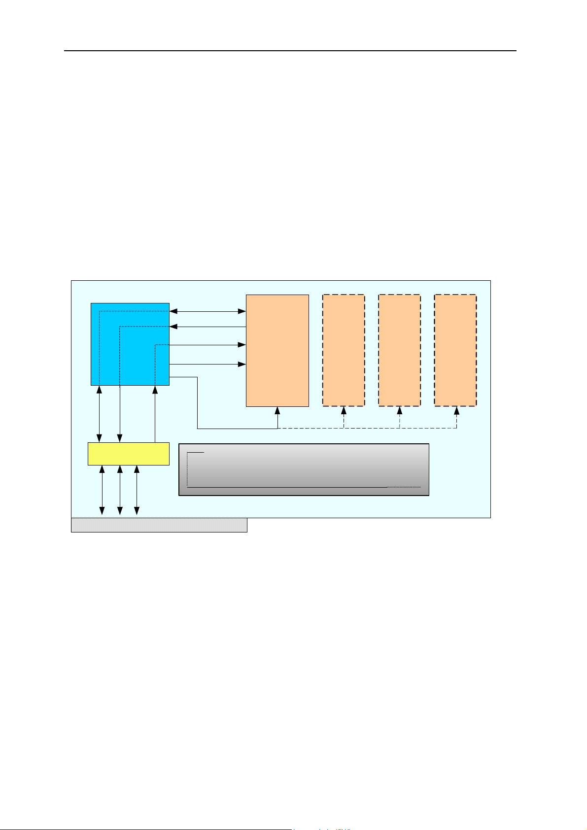
8 Hardware overview
You need to be aware of the assumptions the SMT6035 makes about hardware
resources. This section is a basic overview of the main hardware features
supported, and shows how the SMT6035 interacts with them. The carrier board
User Manual includes a more detailed description of the hardware.
CPLD (BAR 1)
Comport
IntD
PCI Bridge (BAR 0)
Comport
IntA
PCI
LINT (IIOF2)
Comport
IIOF1
IIOF2
IIOF0
Reset
The Bridge chip forms the link between the host and the DSP.
The mailbox registers are contained in the bridge chip.
TIM site 1
(Boot loader
supports
loading binary
files from
comport)
TIM site
2
TIM site
3
TIM site
4
Figure 2 - Overview of the hardware.
The figure above illustrates the main hardware concepts of a typical Sundance
carrier board.
8.1 Comport
A comport is a generic mechanism for transferring data between the
components of your system. Most TIMs have several comports that can be
used to connect to each other or to the host. These links are usually made with
FMS cables, but some boards have built-in connections that can be controlled
by carrier board registers; the User Manual for your board will describe these
User Manual - Version 2.2, 04/01/07; © Sundance Italia S.R.L.
Page 10

Version 2.2 Page 10 of 39 SMT6035 User Manual
registers in detail. The standard configuration will connect comport 3 on TIM site
1 to the host.
8.2 The CPLD
The CPLD is used to configure the carrier board. It allows you to select the
direction of signals on the carrier board, to select interrupt sources and to set
the routing of the IIOF lines. The CPLD registers are mapped onto BAR1 of the
PCI bridge chip. The carrier board User Manual includes additional information
about the CPLD.
8.3 State of the IIOF lines
The LINT (local interrupt) line on the global bus side of the PCI bridge chip can
be switched to any of the IIOF lines that go to the DSP.
The initial configuration of the IIOF lines is as follows:
Line Use or direction
IIOF0 Host to DSP
IIOF1 DSP to Host
IIOF2 Used internally by the SMT6035 to signal mailbox interrupts
to the DSP.
Table 1 - Initial state of the IIOF lines when the SMT6035 starts up.
8.4 The PCI bridge chip
The bridge chip represents the link between the host and the carrier board; it
connects the local bus on the carrier board with the PCI bus of the host.
Specific openings are provided to act like windows through which the local bus
can access data on the PCI bus.
The internal PCI bridge registers are mapped onto BAR0, allowing access by
both the local bus (DSP side) and the PCI bus (host side). Contained in the
bridge chip are the 16 x 8-bit mailbox registers (Section 14).
The bridge chip provides a local bus interrupt line (LINT) as well as a PCI bus
interrupt line (IntA). These interrupt lines allow the host side to interrupt the DSP
and vice versa.
More information about the bridge chip can be found at
http://www.quicklogic.com
.
User Manual - Version 2.2, 04/01/07; © Sundance Italia S.R.L.
Page 11

Version 2.2 Page 11 of 39 SMT6035 User Manual
9 Software design
9.1 Interface mechanism
The software implementation has a C++ style interface, which provides pointers
to the hardware.
libsmtdrv.so exports functions that gather information about the installed boards
and provide interface pointers for later use.
To use the SMT6035, you have to:
• Obtain an interface pointer to the hardware by calling SmtOpenBoard().
• Use the interface pointer to call functions related to the hardware.
Example:
IFHw *pBoard = SmtOpenBoard(0); // open the first board found
pBoard->ResetTIMs();
pBoard->BinaryLoad("MyFile.app");
10 Functions exported by libsmtdrv.so
This section describes each of the functions exported by Libsmtdrv.so. These
functions are described in the header file SmtDrv.h.
10.1 SmtOpen
Initialize the SMT6035 library. Applications must call this function before using
any other features of the library.
Prototype
SMTRet SmtOpen( void );
Return value
The function returns SMT_OK on successful completion; other return values
indicate failure. SmtGetError() can be used to translate error values into
descriptive strings.
User Manual - Version 2.2, 04/01/07; © Sundance Italia S.R.L.
Page 12

Version 2.2 Page 12 of 39 SMT6035 User Manual
10.2 SmtGetBoardCount
Returns the number of Sundance carrier boards found in the system.
Prototype
DWORD SmtGetBoardCount(void);
Return value
The number of Sundance carrier boards found in the system.
10.3 SmtOpenBoard
Obtains an interface to a Sundance carrier board.
Prototype
IFHw * SmtOpenBoard( UINT nIndex );
Parameters
nIndex The zero-based index of the carrier board. nIndex should
be in the range 0 <= nIndex < GetBoardCount().
Return value
The return value is an interface of type IFHw that can be used to access the
carrier board. Please refer to section 11 for a description of the functions
provided by this interface. NULL (0) is returned on error.
10.4 SmtCloseBoard
Closes an interface to a board. You must not use the interface pointer after
calling SmtCloseBoard().
Prototype
void SmtCloseBoard( UINT nBoard );
Parameters
nBoard The index of the board that should be closed. nIndex
should be in the range 0 <= nIndex < GetBoardCount().
User Manual - Version 2.2, 04/01/07; © Sundance Italia S.R.L.
Page 13

Version 2.2 Page 13 of 39 SMT6035 User Manual
10.5 SmtGetBoardIndex
Finds the zero based index for the board at the specified base address.
Prototype
INT SmtGetBoardIndex( UINT nBaseAddress );
Parameters
nBaseAddress The board base address. The base address is the PCI
address that the host operating system has assigned to
the carrier board.
Return value
The zero based index of the board at base address is nBaseAddress.
The function returns -1 when no board is found.
10.6 SmtGetBoardInfo
Returns information about a carrier board. For a description of the information
returned see the remarks.
Prototype
SMTRet SmtGetBoardInfo( UINT nIndex, SMTBI& info );
Parameters
nIndex The zero based index of the board.
info The structure that is to be filled with the board
information.
Return value
The function returns SMT_OK on successful completion; other return values
indicate failure. SmtGetError() can be used to translate error values into
descriptive strings.
Remarks
The information is stored in the SMTBI structure described below:
struct SMTBI {
SMTBoardType Type;
char cszType[32];
UINT nBase;
UINT nRange;
SMTHWStatus HwStatus;
SMTLock LockStatus;
User Manual - Version 2.2, 04/01/07; © Sundance Italia S.R.L.
Page 14

Version 2.2 Page 14 of 39 SMT6035 User Manual
SMTOpen OpenRes;
};
The information returned is summarized in the table below:
Field Description
Type Specifies the type of carrier board.
cszType String description of the type of carrier board. For
example “SMT310Q”
nBase The PCI base address that the host operating system
has assigned to this carrier board.
nRange The number of bytes from the base address that has
been assigned to this carrier board.
HwStatus The hardware status of the carrier board. Valid values
are SMT_On and SMT_Off.
LockStatus If the carrier board could be opened successfully, this
value will be SMT_LOCK_OK.
OpenRes If the software was initialized correctly, this value will be
SMT_OPEN_OK.
10.7 SmtGetError
Returns a string description of the error value.
Prototype:
const char * SmtGetError( SMTRet Error );
Parameters:
Error The error value.
Return value:
A textual translation of the error value.
10.8 SmtGetDLLVer
Returns the version information for libsmtdrv.so.
Prototype:
Parameters:
SMTRet SmtGetDLLVer( UINT &nMaj, UINT &nMin );
nMaj Receives the major version number.
User Manual - Version 2.2, 04/01/07; © Sundance Italia S.R.L.
Page 15

Version 2.2 Page 15 of 39 SMT6035 User Manual
NMin Receives the minor version number.
Return value:
The function returns SMT_OK on successful completion; other return values
indicate failure. SmtGetError() can be used to translate error values into
descriptive strings.
10.9 SmtGetPluginVersion
Returns version information for the kernel mode plug-in.
Prototype:
void SmtGetPluginVersion( UINT &nMaj, UINT &nMin );
Parameters:
nMaj Receives the major version number.
NMin Receives the minor version number.
User Manual - Version 2.2, 04/01/07; © Sundance Italia S.R.L.
Page 16

Version 2.2 Page 16 of 39 SMT6035 User Manual
11 Functional description
Once the interface to the hardware has been obtained by calling
SmtOpenBoard(), it allows you to access the following features available on
various Sundance carrier boards.
Functionality SMT320-327 SMT300-310-310Q
Comport access Supported Supported
Downloading files Supported Supported
Mailboxes Not supported Supported
High speed channel Not supported Supported
Board state Supported Supported
Read and write carrier board registers Supported Supported
PCI bridge chip register access Supported Supported
DSP Interrupt Supported Supported
Table 2 - Supported functionality for Sundance carrier boards
12 Host comport
The simplest and most general I/O mechanism that can be used to communicate
between the host and the Root DSP is the host comport.
It is a sequential, bi-directional link that gives typical transfer speeds of up to
2MB/s. It is also used for loading programs into the DSP. Please refer to the user
manual of your TIM for more information about the supported file formats.
Blocking functions are used to transfer data over this link: they do not return until
the transfer has completed. To force completion of pending read or write
operations, throw an exception of type SMTExc using CpCancel().
12.1 CpRead
Reads data from the comport.
Prototype:
Parameters:
void IFHw::CpRead( void *pBuf, UINT nBytes )
pBuf Pointer to a buffer receiving the data read from the
comport.
User Manual - Version 2.2, 04/01/07; © Sundance Italia S.R.L.
Page 17

Version 2.2 Page 17 of 39 SMT6035 User Manual
nBytes The number of bytes read from the comport.
12.2 CpWrite
Writes data to the comport.
Prototype:
void IFHw::CpWrite( const void *pData, UINT nBytes )
Parameters:
pData Pointer to the buffer containing the data to write to the
comport.
nBytes The number of bytes to be written.
12.3 CpCancel
Cancels any pending comport operation. Pending operations are those that
have been started but still haven’t reached completion. For example, suppose
that a thread is calling CpRead() and is waiting for the DSP to write some data.
Now, if some other thread calls CpCancel(), an exception will be raised in the
thread that started the read operation. The exception will be of type SMTExc.
Prototype:
void IFHw::CpCancel( void )
13 Downloading files
The host comport is the standard route for loading programs into your DSP.
Each TIM in your system will load a “bootloader” from its flash ROM when it
comes out of reset. This bootloader performs various housekeeping operations to
initialise the TIM and then waits until data arrives on any of its comports. The first
comport to become active is selected and the data it provides is loaded into the
DSP and executed. The host comport only gives you access to the Root TIM of
your DSP board. You can load any other TIMs in your system indirectly via the
root with explicit code. This is done automatically if you are loading a 3L Diamond
application.
13.1 BinaryLoad
The contents of the specified file will be sent down the host link unchanged, one
32-bit word at a time. Each 32-bit word is constructed from four bytes in the file,
the least significant byte coming first. This function is most commonly used to
load Diamond .app files that contain information allowing all processors in a
network to be loaded. It is important that the file you specify to be a multiple of 4
User Manual - Version 2.2, 04/01/07; © Sundance Italia S.R.L.
Page 18

Version 2.2 Page 18 of 39 SMT6035 User Manual
bytes in size. If this is not the case, the function will round the size down to the
nearest four bytes, and remaining bytes will not be sent to the DSP.
Prototype:
void IFHw::BinaryLoad( const char *pcszFilename, PrgssInd
*pProgress = 0 )
Parameters:
pcszFilename The filename of the binary file to download to the Root
DSP.
pProgress Pointer to a structure that will obtain progress reports
during the download. If this value is zero, no progress is
reported.
13.2 CoffLoad
Loads a COFF file to the Root DSP.
Prototype
void IFHw::CoffLoad( const char *pcszFilename,
TIM_TYPE Tim=TIM_UNKNOWN,
PrgssInd *pProgress = 0 )
Parameters
pcszFilename The filename of the COFF file to be downloaded into the
Root DSP.
Tim The type of TIM.
pProgress Optional pointer to a progress indication object.
14 Mailboxes
The mailboxes provided by the PCI bridge chip allow the host and the Root DSP
to send signals to each other.
Note that mailboxes are intended as a signalling mechanism and not as a way of
passing large amounts of data.
The V3 bridge chip provides 16 x 8-bit mailboxes, which are combined to form
two independent 32-bit, bi-directional mailboxes numbered 0 and 1.
User Manual - Version 2.2, 04/01/07; © Sundance Italia S.R.L.
Page 19

Version 2.2 Page 19 of 39 SMT6035 User Manual
SMT6025
Mailbox 0
Mailbox 1
PCI Bridge chip registers
Mb
Mb
MB1
Mb5
Mb9
10
Mb
14
13
Mb3
Mb7
Mb
11
Mb
15
MB2
Mb6
MB0
Mb4
Mb8
Mb
12
Figure 3 - Mailboxes with the SMT6035
IMPORTANT: Mailbox 1 is used internally by the HSC, leaving only Mailbox 0
available to user applications. See the HSC section 15.
The V3 bridge chip uses interrupts to notify both the PCI and the local bus side of
mailbox activity. The SMT6035 configures these interrupts to provide blocking
mailbox read and write functions on the host. These functions will block until the
DSP performs the required action. When the host side writes to a mailbox, the
write function will block (wait) until the DSP side had read the mailbox value.
Similarly when the host reads a mailbox, the function will block until the DSP
writes a mailbox value.
The host CPU usage is virtually zero during function blocking, as the blocking
behaviour of the mailbox functions is achieved by the use of interrupts.
Although you are free to develop your own mailbox code on the DSP side, we
recommend you to use 3L Diamond
©
on the DSP side, as it provides built-in
support for the mailboxes.
14.1 MbWrite
Writes a value to a mailbox.
Prototype
void IFHw::MbWrite( UINT nBox, DWORD dwValue )
Parameters
nBox The target mailbox. Must be zero.
dwValue The value to write to the mailbox.
User Manual - Version 2.2, 04/01/07; © Sundance Italia S.R.L.
Page 20

Version 2.2 Page 20 of 39 SMT6035 User Manual
14.2 MbRead
Read a value from a mailbox.
Prototype
DWORD IFHw::MbRead( UINT nBox )
Parameters
nBox The target mailbox. Must be zero.
14.3 MbCancel
Cancels a pending mailbox operation. The thread waiting on a pending mailbox
operation will throw an exception of the type SMTExc when MbCancel() is
called.
Prototype
void IFHw::MbCancel( UINT nBox )
Parameters
nBox The target mailbox. Must be zero.
15 High speed channel
The SMT6035 provides 8 “High Speed Channels”. A High-speed channel is a
powerful and simple way to communicate data between the host and the root
DSP.
15.1 Data transfer mechanism
The root DSP performs all transfers associated with the High-speed channel,
using the “Global bus” on the root TIM to access resources on the carrier board.
For more information about the global bus, please refer to the general firmware
description document. The root DSP sets up the required DMA operations to
execute the transfers associated with the HSC.
Figure 4 shows the root DSP as having access to the SRAM on the carrier
board as well as the to PCI bridge chip. By setting up registers in the PCI bridge
chip, the root DSP can gain access to the PCI memory space.
User Manual - Version 2.2, 04/01/07; © Sundance Italia S.R.L.
Page 21

Version 2.2 Page 21 of 39 SMT6035 User Manual
Host system
Host PCI memory space
Your application running on
host system
Carrier board
PCI Bridge
chip
SRAM
Local bus
Global bus
DSP DMA
engine
Root TIM
Figure 4 - Overview of data transfer mechanism
The SRAM on the carrier board is divided into 8 same-size sections, each
representing a high-speed channel. Each section contains:
• The memory descriptor list for any PCI memory associated with this
channel.
• Arguments (parameters) associated with this channel. Used as a shared
memory region between the host and the root DSP.
Note - The host application can gain access to the SRAM on the carrier board,
because the SRAM is mapped into the virtual memory space of the host
application. This is taken care of by the PCI bridge chip.
On the DSP side, 3L Diamond
©
provides built-in support for the HSC.
There are three mechanisms used to transfer data between the host and the
root DSP.
• Control words.
• SRAM arguments.
• PCI memory access.
User Manual - Version 2.2, 04/01/07; © Sundance Italia S.R.L.
Page 22

Version 2.2 Page 22 of 39 SMT6035 User Manual
15.2 Control words
Control words form the basis of the HSC operation, and are used to
synchronize events between the host and the root DSP. The control word
mechanism employs Mailbox 1 as described in section 14.
In all data transfers between the host and the DSP, control words are used to
indicate the type of transfer as well as the data size. They ensure that both the
host and the root DSP can safely access shared memory resources.
The 32 bit value used with mailbox 1 is interpreted as a HSC_WORD.
typedef struct {
UINT32 Data :25; /* Data value */
UINT32 Fn : 4; /* Function code */
UINT32 Channel : 3; /* Channel selector */
} HSC_WORD;
It contains the following information:
• Data field
• Function (command).
• Channel number.
The function value specifies which function will be performed; it may also
contain status or return values. There are a total of 16 possible functions, with
the following 10 functions defined by default:
Value Define Description
0 HSC_OK OK reply
1 HSC_Error Error reply
2 HSC_OpenHandler Host opens a handler
3 HSC_CloseHandler Host closes a handler
4 HSC_SramToHost DSP writes SRAM argument area
5 HSC_HostToSram DSP reads SRAM argument area
6 HSC_OpenPci Host sets up PCI memory
7 HSC_ClosePci Host releases PCI memory
8 HSC_PciToHost DSP write PCI memory space
9 HSC_HostToPci DSP read PCI memory space
User Manual - Version 2.2, 04/01/07; © Sundance Italia S.R.L.
Page 23

Version 2.2 Page 23 of 39 SMT6035 User Manual
You are free to define your own functions in the range 10 – 15. Please refer to
the custom handler section 15.5.4. If this range is insufficient for your
application, you can always pass arguments in the SRAM arguments area to
distinguish your functions.
15.2.1 Protocol between DSP and host
The DSP is always in charge of transfers. This means that the following
protocol must be maintained between the host and the DSP.
The DSP
• Sends a control word to the host.
• Waits for a reply.
The Host
• Waits for a control word from the DSP.
• Performs some action.
• Sends a reply back to the DSP.
The control words are used to synchronize access to memory regions.
They also convey status and error control values. This basic signalling
mechanism is used for both the SRAM and the PCI-type memory
accesses, but can be enhanced to create your own custom protocols.
15.2.2 DSP writing to the host
Before the DSP transfers data to the host, it places the data in the
appropriate memory (PCI or SRAM) and then sends a control word to
the DSP indicating to the host that the data is available. When the host
has replied, the DSP can be sure that the host has processed the data.
Host DSP Section
Waits for control word Writes to shared memory (PCI
Sends control word to host
Receives control word Waits for host reply Sect 15.6.14
or SRAM)
Processes data
Sends reply to DSP Sect 15.6.15
Write operation complete
User Manual - Version 2.2, 04/01/07; © Sundance Italia S.R.L.
Page 24

Version 2.2 Page 24 of 39 SMT6035 User Manual
15.2.3 DSP reading from the host
Before the DSP reads data from the host, it writes a control word to the
host indicating it. The host reads this command from the DSP, places
the data in the appropriate memory and replies to the DSP when it has
done so.
Host DSP Section
Waits for control word Sends control word to host
Receives control word Waits for host’s reply Sect 15.6.16
Prepares shared memory
(PCI or SRAM)
Sends reply to DSP Sect 15.6.17
Read operation complete
15.3 SRAM arguments
The SRAM acts as a shared memory buffer between the DSP and the host. For
each channel an area of the SRAM is reserved for communicating data. This
area is called the argument space, and is limited to 64 Kbytes per channel.
The SMT6035 provides utility functions that allow the host to access the
parameter area for each channel. Similarly, on the DSP side, 3L Diamond
utility functions with which you can access the SRAM argument areas.
15.4 PCI memory access
In case of PCI memory access, the DSP can use the host PCI memory space
via the PCI bridge chip. The host memory has to be locked before the DSP will
be able to safely gain access this memory. The host operating system must not
page to disk any locked memory, and must ensure that the memory remains at
a fixed location.
©
has
With the SMT6035, the PCI memory will be automatically locked when you
define a virtual channel. During this stage, a memory descriptor list (MDL) for
the locked down memory will be copied into the SRAM for later use by the DSP.
It is possible to lock a contiguous memory region. However, this memory region
has to be provided from the non-paged system memory pool, and this is a
scarce system resource. It is not advisable to lock large amounts of contiguous
memory on the host, as this will seriously degrade system performance and
may make the host system unstable.
Using a high-speed channel (HSC), it is possible to transfer blocks of up to
16MB of data at a time between the host and the root DSP. Typical transfer
User Manual - Version 2.2, 04/01/07; © Sundance Italia S.R.L.
Page 25

Version 2.2 Page 25 of 39 SMT6035 User Manual
speeds of 40MB/s may be achieved although actual performance may vary from
system to system.
15.5 Handlers
The handler mechanism allows you to create custom host-side software that
interacts with the DSP, under DSP control. You may wish to create a handler
that interacts with the user on the host system by displaying a dialog box, or to
display data to the user in some custom format. Perhaps you might want to
obtain data from the host system for processing by the DSP. In all these cases,
a handler might be just what you need.
A handler takes the form of a DLL, which can be loaded on request from the
DSP. This allows the DSP to set up the host-side software to perform actions on
its behalf.
Creating a custom handler is not mandatory, because there is a default handler
that provides basic functionality.
15.5.1 Opening a handler
Before the DSP can open a handler on the host, it writes the details of
the handler in the SRAM argument block for the relevant channel. It
then sends a HSC_OpenHandler control word to the host. The format
of the data block required in the SRAM is described by the following
structure, which can be found in smthsc.h.
typedef struct {
int Code;
int Arg;
char Dll[128]; /* name of handler dll,
} HSC_Param_OpenHandler;
The DSP is free to specify values for Code and Arg. These values can
be interpreted by the HandlerEntry() function to select between multiple
possible handlers. Anyway, the designer can find his own uses for
these values.
15.5.2 Closing a handler
Once the DSP has finished using a handler, it should send a
HSC_CloseHandler control word to the host. This will cause the host to
unload the handler, and revert back to the default handler.
including .DLL */
User Manual - Version 2.2, 04/01/07; © Sundance Italia S.R.L.
Page 26

Version 2.2 Page 26 of 39 SMT6035 User Manual
15.5.3 The default handler
When no handler is specified for a channel, the default handler will be in
use. It performs the basic functions on the host side associated with a
HSC.
The HSC object exposes a number of functions used with the default
handler. They are listed in the table below.
Function Purpose Section
SramWrite To write data to the SRAM argument
SramRead To read data from the SRAM
SramCancel To cancel a pending SRAM read or
MemWriteStart To start a PCI write operation. 15.6.14
MemWriteDone To complete a PCI write operation. 15.6.15
MemReadStart To start a PCI read operation. 15.6.16
MemReadDone To complete a PCI read operation. 15.6.17
If you specify your own handler, then probably the functionality provided
by the functions listed above will be somehow incorporated into the
custom behaviour of your handler. While a custom handler is in effect,
the functions above will no longer work. The default handler will be
reinstated when a custom handler is closed, or when the DSP is reset
using the SMT6035.
15.5.4 Custom handlers
15.6.9
area.
15.6.10
arguments area
15.6.11
write operation.
It is possible to create your own handler for user specific requirements.
Please refer to the SmtHscFile library installed with the SMT6035 for an
example of a custom handler. This handler allows the DSP to access
files on the host system by performing the host side functions on behalf
of the DSP.
A handler DLL must export the following function. This function will be
called by the libsmtdrv.so when the DSP specifies this handler.
extern "C" __declspec(dllexport)
int HandlerEntry( HSC *pHsc,
int Code,
int Arg,
HANDLE hCancel );
where:
User Manual - Version 2.2, 04/01/07; © Sundance Italia S.R.L.
Page 27

Version 2.2 Page 27 of 39 SMT6035 User Manual
pHsc Is a pointer to the HSC object.
Code Is a value specified by the DSP.
Arg Is a value specified by the DSP.
hCancel Is an event that can be set at any time to signal
the handler to terminate.
The handler function needs to process control words from the DSP, and
will always take the following form:
Try {
Control = GetControlFromDSP().
If(control == HSC_CloseHanlder )
{
Cleanup
Return HSC_HANDLER_OK;
}
Process the control word.
Send reply back to DSP
}
catch( SMTExc &e)
{
cleanup
throw e
}
15.5.5 Development guidelines
An exception mechanism is used to implement the handler code.
A handler can throw an exception of type SMTExc at any time. If your
handler has any cleanup to do, you need to catch this type of exception
and perform any cleanup necessary.
Along with the other parameters passed into the HandlerEntry()
function, a handle value of an event is passed to indicate to the handler
that it needs to terminate. Whenever you wait for an event in the
handler, you need to also wait for this cancellation handle. If this
cancellation event gets signalled, the handler needs to return
immediately with the value HSC_HANDLER_CANCEL.
Your handler code may look like this:
HANDLE h[] = {hCancel,hMyEvent};
DWORD dw = WaitForMultipleObjects( 2, h, FALSE,INFINITE);
if (dw == WAIT_OBJECT_0) return HSC_HANDLER_CANCEL;
If the handler receives a HSC_CloseHandler, it should return
HSC_HANDLER_OK.
User Manual - Version 2.2, 04/01/07; © Sundance Italia S.R.L.
Page 28

Version 2.2 Page 28 of 39 SMT6035 User Manual
15.6 Function reference
All the HSC interaction is by means of a HSC object. This object exposes all the
functions associated with a high-speed channel. You get an interface to a HSC
object by calling HscInterface().
15.6.1 HscInterface
Returns an interface to a HSC object that represents the specified highspeed channel.
Prototype:
HSC * IFHw:: HscInterface (UINT Channel)
Parameters:
Channel The number of the channel you get an interface to.
Valid channel numbers are in the range 0 to 7.
Once you have acquired the interface to the HSC object, you may call
any of the following functions on that interface.
15.6.2 GetIFHw
Obtains a pointer to the hardware interface of this HSC object.
Prototype
IFHw * HSC::GetIFHw( void )
Parameters
None
15.6.3 GetChannel
Returns the channel number for this HSC object.
Prototype
UINT HSC::GetChannel( void )
Parameters
None
15.6.4 CtrlGet
Obtains a control word from the DSP. This function will block until the
host receives a control word from the DSP.
Prototype
HSC_WORD HSC::CtrlGet( void )
User Manual - Version 2.2, 04/01/07; © Sundance Italia S.R.L.
Page 29

Version 2.2 Page 29 of 39 SMT6035 User Manual
Parameters
None
Notes:
This function will throw an exception of type SMTExc if CtrlCancel() is
called.
15.6.5 CtrlPut
Sends a control word to the DSP. This function will block until the DSP
has acquired the control word from the host.
Prototype
void HSC::CtrlPut( HSC_WORD w )
Parameters
w The HSC control word to be sent to the DSP.
Notes:
This function will throw an exception of type SMTExc if CtrlCancel() is
called.
15.6.6 CtrlCancel
Cancels any pending control words. Any thread calling CtrlPut or
CtrlGet will throw an exception of type SMTExc.
Prototype
void HSC::CtrlCancel( void )
Parameters
None
15.6.7 ArgsPut
Writes arguments (parameters) to the SRAM area for this channel.
Prototype
void HSC::ArgsPut( UINT nBytes, void *pMem )
Parameters
nBytes The size of the memory pointed to by pMem. The
maximum size allowed is 64KB.
PMem Pointer to the parameters to be copied into the
SRAM.
User Manual - Version 2.2, 04/01/07; © Sundance Italia S.R.L.
Page 30

Version 2.2 Page 30 of 39 SMT6035 User Manual
15.6.8 ArgsGet
Reads arguments (parameters) from the SRAM area for this channel.
Prototype
void HSC::ArgsGet( UINT nBytes, void *pMem )
Parameters
nBytes The size of the memory pointed to by pMem. The
maximum size allowed is 64KB.
PMem Pointer to the buffer that will receive the
parameters from the SRAM.
15.6.9 SramWrite
Writes arguments to the SRAM area of the HSC object.
Prototype
UINT HSC::SramWrite( UINT nBytes, void *pMem )
Parameters
nBytes The size of the memory pointed to by pMem.
pMem Points to the host memory to be written to the
Return value
The number bytes actually read by the DSP.
15.6.10 SramRead
Reads arguments from the SRAM area of the HSC object.
Prototype
UINT HSC:: SramRead( UINT nBytes, void *pMem )
Parameters
nBytes The size of the memory pointed to by pMem.
pMem Points to the host memory that will receive the
Return value
The number of bytes that were written by the DSP.
argument section of the SRAM for this channel.
argument section of the SRAM for this channel.
15.6.11 SramCancel
Cancels any pending SRAM read or write functions.
Prototype
User Manual - Version 2.2, 04/01/07; © Sundance Italia S.R.L.
Page 31

Version 2.2 Page 31 of 39 SMT6035 User Manual
Void HSC:: SramCancel( void )
Parameters
None
15.6.12 MemOpen
Associates a region of PCI memory space with a virtual high-speed
channel.
Prototype
Void * HSC::MemOpen( UINT Bytes, void *pMem,
bool bLocked=false)
Parameters
nChannel The number of the channel to open. Valid channel
numbers are in the range 0 to 7.
pMem Points to the host memory to be associated with
this channel.
Bytes The size of the memory pointed to by pMem.
bLocked Specifies that the memory pointed to by pMem has
already been locked, and should not be unlocked
when the channel is closed later on.
15.6.13 MemClose
Dissociates the region of PCI memory space previously associated with
the channel during the MemOpen() call. If the memory has not been
specified as locked, this function will unlock the memory.
Prototype
void HSC::MemClose( void )
Parameters
None
15.6.14 MemWriteStart
Starts a write operation to the DSP.
Prototype
UINT HSC::MemWriteStart ( void )
Parameters
None
Return value
The function returns the number of bytes the DSP is prepared to read.
User Manual - Version 2.2, 04/01/07; © Sundance Italia S.R.L.
Page 32

Version 2.2 Page 32 of 39 SMT6035 User Manual
15.6.15 MemWriteDone
Completes a write operation to the DSP.
Prototype
void HSC::MemWriteDone( UINT nBytes )
Parameters
nBytes The number of bytes written by the host.
Return value
None
15.6.16 MemReadStart
Starts a write operation to the DSP.
Prototype
UINT HSC::MemReadStart ( void )
Parameters
None
Return value
The function returns the number of bytes the DSP is prepared to write.
15.6.17 MemReadDone
Completes a read operation from the DSP.
Prototype
void HSC::MemReadDone( UINT nBytes )
Parameters
nBytes The number of bytes actually read by the host.
15.6.18 MemCancel
Cancels any pending memory read or write operation. The cancelled
thread will throw an exception of the type SMTExc.
Prototype
void HSC::MemCancel( void )
Parameters
None
User Manual - Version 2.2, 04/01/07; © Sundance Italia S.R.L.
Page 33

Version 2.2 Page 33 of 39 SMT6035 User Manual
15.6.19 RecallHandlers
During the normal procedure for closing a handler, the DSP sends a
HSC_CloseHandler control word to the host.
In some cases, the host-side software needs to unload the handler, and
to break the connection between the DSP and the handler.
Calling RecallHandlers() will signal any running handlers to terminate. It
will also put the host into a state where it will absorb all the control
words received from the DSP without doing anything with them. The
DSP will no longer be able to communicate with any handlers. This
state will last until the DSP is reset, in which case the default handler
will be reselected.
Prototype
void IFHw::RecallHandlers( void )
Parameters
None
16 Board state
You usually need to reset the TIMs on the carrier board before downloading your
application.
16.1 ResetTIMs
Resets the TIMs on the carrier board.
Prototype
void IFHw::ResetTIMs(void)
16.2 ResetBoard
Resets the carrier board. This function resets the TIMs and the JTAG controller.
Prototype
void IFHw::ResetBoard(void)
17 Read and write carrier board registers
The SMT6035 gives you access to the carrier board registers. Thus, you can
perform any low level accesses that you might require.
Please refer to the carrier board User Manual for a description of the carrier
board registers and BAR address mapping.
The register access is specified by a BAR address and offset values.
User Manual - Version 2.2, 04/01/07; © Sundance Italia S.R.L.
Page 34

Version 2.2 Page 34 of 39 SMT6035 User Manual
The number at the end of each element of the following list of functions indicates
the number of bits that will be read or written. For each function:
nBar BAR to use.
nOffset Offset into the BAR to access.
17.1 Read32
Reads 32 bits from the address specified.
Prototype
DWORD IFHw::Read32( UINT nBar, UINT nOffset )
17.2 Read16
Reads 16 bits from the address specified.
Prototype
DWORD IFHw::Read16( UINT nBar, UINT nOffset )
17.3 Read8
Reads 8 bits from the address specified.
Prototype
DWORD IFHw::Read8( UINT nBar, UINT nOffset )
17.4 Write32
Writes 32 bits to the address specified.
Prototype
void IFHw::Write32( UINT nBar, UINT nOffset, DWORD dword
17.5 Write16
Writes 16 bits to the address specified.
Prototype
void IFHw::Write16( UINT nBar, UINT nOffset, WORD word )
17.6 Write8
Writes 8 bits to the address specified.
Prototype
void IFHw::Write8( UINT nBar, UINT nOffset, BYTE byte )
User Manual - Version 2.2, 04/01/07; © Sundance Italia S.R.L.
Page 35

Version 2.2 Page 35 of 39 SMT6035 User Manual
18 PCI bridge chip register access
The Sundance carrier boards use a V3 bridge chip to interface to the PCI bus.
Certain resources, such as I/O address range, memory range and interrupts, are
assigned to the carrier board when the host boots. Information about these
resources is kept in the PCI bridge chip registers.
The PCI bridge chip registers hold, set up and control values; they implement the
mailbox registers too. Although direct access to the mailbox registers (offset
0XC0 – 0xCF) is possible, it is strongly recommended that you use the SMT6035
built-in support (see section 14). This is a consequence of the design of the
interrupt service routine used by the SMT6035.
A special bus cycle on the PCI bus is used to access the PCI registers of the
carrier board. This special bus cycle does not use any BAR mapping, therefore it
is safe to use even if the BAR addresses have not been set up.
You should not need direct access to the PCI registers for most systems. Please
make sure that you know what you are doing before accessing the PCI bridge
chip registers. Writing incorrect values to these registers will almost certainly
crash the host.
For a detailed description of the PCI bridge chip registers, please refer to the
User Manual for the bridge chip here: http://www.quicklogic.com
.
The number at the end of the following function names indicates the number of
bits being read or written.
18.1 PciRead32
Reads 32 bits from the PCI register specified.
Prototype
DWORD IFHw::PciRead32( DWORD dwReg)
18.2 PciWrite32
Writes 32 bits to the PCI register specified.
Prototype
void IFHw::PciWrite32(DWORD dwReg, DWORD dwValue )
18.3 PciWrite16
Writes 16 bits to the PCI register specified.
Prototype
void IFHw::PciWrite16( DWORD dwReg, WORD wValue )
User Manual - Version 2.2, 04/01/07; © Sundance Italia S.R.L.
Page 36

Version 2.2 Page 36 of 39 SMT6035 User Manual
18.4 PciWrite8
Writes 8 bits to the PCI register specified.
Prototype
void IFHw::PciWrite8( DWORD dwReg, BYTE cValue )
18.5 PciVirtualAddr
Returns the virtual memory address for the Base Address Region specified.
Prototype
void IFHw::PciVirtualAddr( UINT nBar, void *&pVirtAddr )
19 DSP interrupt
The DSP (C40) interrupt is a mechanism that was inherited from a previous
generation of carrier boards and is still supported in the current generation.
The DSP interrupt allows the DSP to interrupt the host.
The DSP can generate a DSP interrupt to the host by toggling the IIOF1 line.
With SMT6035, you can attach an interrupt function to this event. Unlike
mailboxes, no data is transferred with this type of interrupt.
Please refer to the examples for the DSPInt interrupt example.
19.1 DspAttatchInt
Attaches a user-specified function that is to be called when a DSP interrupt
occurs.
Prototype
void IFHw::DspAttatchInt( PFN_DSP_INT pDSPIntFunc )
Parameters
pDSPIntFunc Pointer to the function that is to be called when the DSP
interrupt occurs.
20 Memory allocation
You can make minor improvements in the performance of the HSC by using
contiguous memory. The following functions make possible to allocate such
memory.
User Manual - Version 2.2, 04/01/07; © Sundance Italia S.R.L.
Page 37

Version 2.2 Page 37 of 39 SMT6035 User Manual
20.1 MemLock
Locks a memory buffer. This function can be used to lock a contiguous or
scatter-gather type buffer. In case of a scatter-gather type buffer, the user has
to allocate the memory before calling this function.
Prototype
Void * IFHw:: MemLock( UINT nBytes, void *pBuf,
MDLEntry * pEntries, UINT &nEntCnt)
Parameters
nBytes The size of the memory. For scatter-gather memory, this
specifies the size of the memory pointed by pBuf. For
contiguous memory, this specifies the required memory
size.
pBuf For scatter gather memory, this points to the memory.
For contiguous memory, this needs to be zero.
pEntries Optional pointer to a buffer that will receive the memory
descriptor list (MDL). When this value is zero, no MDL
list is returned.
nEntCnt This is both an input and an output parameter. As an
input parameter, it indicates the number of MDL entries
that the pEntries buffer contains. When the function
returns, this variable contains the actual number of MDL
entries used to describe the memory locked.
Return value
This function returns a pointer to the locked memory, or zero on failure.
The function may fail if you are requesting the MDL list, but do not provide
enough storage for all the MDLs required to describe the locked memory.
In that case, nEntCnt will contain the number of MDL entries required to
describe the memory.
20.2 MemUnlock
Frees a contiguous region of memory that was previously allocated by a call to
MemLock().
Prototype
Parameters
void IFHw::MemUnlock( void *pMem )
pMem Pointer to the memory to unlock.
User Manual - Version 2.2, 04/01/07; © Sundance Italia S.R.L.
Page 38

Version 2.2 Page 38 of 39 SMT6035 User Manual
21 Performance figures
The table below shows typical performance figures obtained with the SMT6035.
Transfer type Read [MB/s] Write [MB/s]
HSC with contiguous memory. 46 40
HSC with Scatter/Gather memory. 40 32
Host comport 2 2
Table 3 - Typical performance figures for various transfer types
22 Handling errors
22.1 Exported functions
Most of the functions exported by libsmtdrv.so return status values. You should
always check the return values from these functions. SmtGetError() can be
used to translate the return values into text strings.
The following is an example code section to show you how to use the functions
exported by libsmtdrv.so.
// Open the library
SMTRet ret = SmtOpen();
if ( ret!=SMT_OK )
{
cout << "Could not open SmtDrv library. The error was ("
<< SmtGetError(ret)
<< ")"
<< endl;
return 0;
}
22.2 Exception mechanism
The functions accessed through the SmtOpenBoard() interface will signal errors
by throwing an exception of type SMTExc. Any of the functions provided by
IFHw may throw an exception of type SMTExc.
You have to surround your function accesses by a try-catch block as shown:
try
{
pB->ResetTIMs();
User Manual - Version 2.2, 04/01/07; © Sundance Italia S.R.L.
Page 39

Version 2.2 Page 39 of 39 SMT6035 User Manual
pB->BinaryLoad( "..\\DSP\\Dsp335.app" );
}
catch( SMTExc &e )
{
cout << "An exception occured. ("
<< e.GetError()
<< ")"
<< endl;
}
Your program will terminate with an un-handled exception dialog should you fail
to catch the exception.
User Manual - Version 2.2, 04/01/07; © Sundance Italia S.R.L.
 Loading...