

Page 1

SMT6025
User Manual
Version 2.9
User Manual (QCF42); Version 2.9, 22/02/02; © Sundance Multiprocessor Technology Ltd. 2002
Page 2

Version 2.9 Page 2 of 45 SMT6025 User Manual
1 Table of Contents
1 Table of Contents ........................................................................................................................... 2
List of abbreviations................................................................................................................................. 5
2 List of figures................................................................................................................................... 5
3 Introduction ..................................................................................................................................... 6
4 Conventions .................................................................................................................................... 7
5 Prerequisites ................................................................................................................................... 7
6 Software Installation and Setup...................................................................................................... 7
6.1 Configuring Visual Studio.......................................................................................................8
7 Design philosophy .......................................................................................................................... 9
8 Hardware overview ....................................................................................................................... 10
8.1 Comport................................................................................................................................ 10
8.2 The CPLD............................................................................................................................. 10
8.3 State of the IIOF lines .......................................................................................................... 11
8.4 The PCI bridge chip .............................................................................................................11
9 Software design ............................................................................................................................ 12
9.1 Interface mechanism............................................................................................................ 12
10 Functions exported by SmtDrv.dll................................................................................................. 12
10.1 SmtOpen .............................................................................................................................. 12
10.2 SmtGetBoardCount.............................................................................................................. 12
10.3 SmtOpenBoard ....................................................................................................................13
10.4 SmtCloseBoard .................................................................................................................... 13
10.5 SmtGetBoardIndex............................................................................................................... 13
10.6 SmtGetBoardInfo .................................................................................................................14
10.7 SmtGetError ......................................................................................................................... 15
10.8 SmtGetDLLVer..................................................................................................................... 15
10.9 SmtGetPluginVersion........................................................................................................... 15
11 Functional description................................................................................................................... 16
12 Host comport................................................................................................................................. 16
12.1 CpRead ................................................................................................................................ 16
12.2 CpWrite ................................................................................................................................ 17
12.3 CpCancel.............................................................................................................................. 17
13 Downloading files.......................................................................................................................... 17
13.1 BinaryLoad ........................................................................................................................... 17
13.2 CoffLoad............................................................................................................................... 18
14 Mailboxes...................................................................................................................................... 18
14.1 MbWrite................................................................................................................................ 19
14.2 MbRead................................................................................................................................ 20
14.3 MbCancel ............................................................................................................................. 20
15 High speed channel ...................................................................................................................... 21
15.1 Introduction .......................................................................................................................... 21
User Manual (QCF42); Version 2.9, 22/02/02; © Sundance Multiprocessor Technology Ltd. 2002
Page 3

Version 2.9 Page 3 of 45 SMT6025 User Manual
15.2 Command word....................................................................................................................22
15.3 Reply word ........................................................................................................................... 23
15.4 Associated data.................................................................................................................... 23
15.4.1 Carrier board SRAM.................................................................................................... 23
15.4.2 Host memory ............................................................................................................... 24
15.5 Channel handler................................................................................................................... 24
15.5.1 Handler not interfacing to host software...................................................................... 25
15.5.2 Handler interfacing to host software............................................................................ 25
15.5.3 Implementing a handler............................................................................................... 27
15.5.4 Opening a channel handler ......................................................................................... 28
15.5.5 Closing a handler......................................................................................................... 28
15.5.6 Development guidelines .............................................................................................. 28
15.6 The HSC object.................................................................................................................... 29
15.6.1 GetIFHw ...................................................................................................................... 29
15.6.2 GetChannel ................................................................................................................. 29
15.6.3 GetHandlerName......................................................................................................... 29
15.6.4 PciOpen....................................................................................................................... 30
15.6.5 PciClose ...................................................................................................................... 30
15.6.6 GetData ....................................................................................................................... 30
15.6.7 SetData........................................................................................................................ 31
15.6.8 ArgsPut........................................................................................................................ 31
15.6.9 ArgsGet ....................................................................................................................... 31
15.7 The default handler .............................................................................................................. 32
15.7.1 SRamPutSync ............................................................................................................. 32
15.7.2 SRamPutDone............................................................................................................. 32
15.7.3 SRamGetSync............................................................................................................. 33
15.7.4 SRamGetDone ............................................................................................................ 33
15.7.5 SramCancel................................................................................................................. 33
15.7.6 PciOpenSync............................................................................................................... 34
15.7.7 PciCloseSync .............................................................................................................. 34
15.7.8 PciPutSync .................................................................................................................. 34
15.7.9 PciPutDone.................................................................................................................. 34
15.7.10 PciGetSync.................................................................................................................. 35
15.7.11 PciGetDone ................................................................................................................. 35
15.7.12 PciCancel .................................................................................................................... 35
16 Board state.................................................................................................................................... 36
16.1 ResetTIMs............................................................................................................................ 36
16.2 ResetBoard .......................................................................................................................... 36
17 Read and write carrier board registers ......................................................................................... 36
17.1 Read32................................................................................................................................. 36
17.2 Read16................................................................................................................................. 36
17.3 Read8................................................................................................................................... 37
17.4 Write32................................................................................................................................. 37
17.5 Write16................................................................................................................................. 37
User Manual (QCF42); Version 2.9, 22/02/02; © Sundance Multiprocessor Technology Ltd. 2002
Page 4

Version 2.9 Page 4 of 45 SMT6025 User Manual
17.6 Write8................................................................................................................................... 37
18 PCI bridge chip register access .................................................................................................... 37
18.1 PciRead32............................................................................................................................ 38
18.2 PciWrite32............................................................................................................................ 38
18.3 PciWrite16............................................................................................................................ 38
18.4 PciWrite8.............................................................................................................................. 38
18.5 PciVirtualAddr ...................................................................................................................... 38
19 DSP interrupt ................................................................................................................................ 38
19.1 DspAttatchInt........................................................................................................................ 39
20 Memory allocation......................................................................................................................... 39
20.1 MemLock.............................................................................................................................. 39
20.2 MemUnlock .......................................................................................................................... 40
21 Performance figures ..................................................................................................................... 40
22 Handling errors ............................................................................................................................. 40
22.1 Exported functions ............................................................................................................... 40
22.2 Exception mechanism .......................................................................................................... 41
23 Extras............................................................................................................................................ 41
23.1 Confidence test dialog..........................................................................................................42
23.2 SMT310Q comport switching dialog .................................................................................... 43
23.3 PCI Information dialog..........................................................................................................44
User Manual (QCF42); Version 2.9, 22/02/02; © Sundance Multiprocessor Technology Ltd. 2002
Page 5

Version 2.9 Page 5 of 45 SMT6025 User Manual
List of abbreviations
BAR Base Address Region
COFF Common Object File Format
CPLD Complex PLDs
DMA Direct Memory Access
DSP Digital Signal Processor
HSC High Speed Channel
JTAG Joint Test Action Group
MDL Memory Descriptor List
PCI Peripheral Component Interconnect
PLD Programmable Logic Device
SMT Sundance Multiprocessor Technology Ltd.
TIM Texas Instruments Module
2 List of figures
Figure 1 - The SMT6025 interfaces to Sundance hardware ....................................... 6
Figure 2 - Directory structure after installing the SMT6025......................................... 8
Figure 3 - Adding the path to the include directories to the compiler options ............. 9
Figure 4 - Adding the path to the library directories to the compiler options ............. 9
Figure 5 - Overview of the hardware. ....................................................................... 10
Figure 6 - Mailboxes with the SMT6025 ................................................................... 19
Figure 7 - Standard HSC transaction........................................................................ 21
Figure 8 - Layout of the SRAM memory ................................................................... 24
Figure 9 - Operation of a handler.............................................................................. 25
Figure 10 - Confidence test dialog............................................................................ 42
Figure 11 - The SMT310Q comport switch dialog .................................................... 43
Figure 12 - The PCI information dialog..................................................................... 44
User Manual (QCF42); Version 2.9, 22/02/02; © Sundance Multiprocessor Technology Ltd. 2002
Page 6
Version 2.9 Page 6 of 45 SMT6025 User Manual
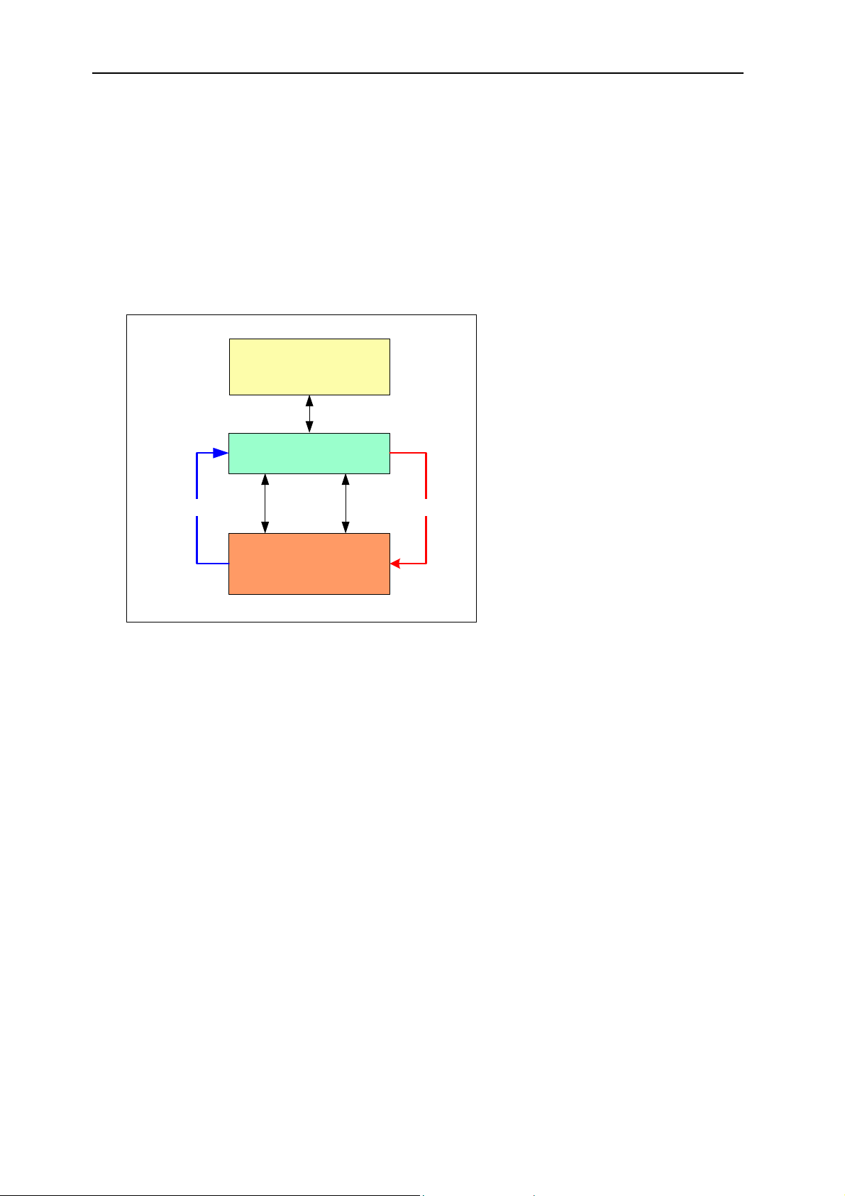
3 Introduction
The SMT6025 SDK provides you with an easy and efficient way to access
Sundance carrier boards. It allows you to control these boards from the host as
well as to exchange data between the carrier board and the host. The
SMT6025 is ideal for customers that wish to develop their own code to interface
with Sundance hardware.
Your application
SMT6025 SDK
Comport
Status
Sundance carrier board
PCI
State control
Figure 1 - The SMT6025 interfaces to Sundance hardware
Figure 1 - shows the SMT6025 forming the link between your application and the
Sundance carrier boards in your system. Having a standard interface such as
the SMT6025 ensures that you do not need to recompile and link your software
when the hardware in the system changes. The SMT6025 hides the details of
the device driver, allowing you to concentrate on the development process.
The SMT6025:
• Provides the host side support for 3L Diamond board services.
• Shorten development time by providing you with a ready-to-use interface to
the hardware.
• Transfer data between the carrier board and the host.
• Downloads applications to the carrier board.
• Obtains information about the carrier board.
• Controls the state of the carrier board.
User Manual (QCF42); Version 2.9, 22/02/02; © Sundance Multiprocessor Technology Ltd. 2002
Page 7

Version 2.9 Page 7 of 45 SMT6025 User Manual
• Gives you a basic building block for more complex systems.
• Provides you with direct access to the hardware registers of the carrier board.
• Provides you with a C++ type interface to the carrier board.
The SMT6025 currently supports the following carrier boards.
Carrier board Description Functionality
SMT300 1 TIM site Compact PCI carrier board Full support
SMT300Q 4 TIM site Compact PCI carrier board Full support
SMT310 1 TIM site PCI carrier board Full support
SMT310Q 4 TIM site PCI carrier board Full support
SMT320 (Obsolete) 4 TIM site PCI carrier board Partial support
SMT327 (Obsolete) 4 TIM site Compact PCI carrier board Partial support
4 Conventions
UINT A 32 bit unsigned value (unsigned int).
DWORD 32 bit unsigned value (unsigned long).
Root TIM The TIM on site 1 of your carrier board.
Root DSP The DSP on TIM site 1.
5 Prerequisites
C++ is used for the software interfaces. Even if you are not familiar with C++, you
should be able to find your way by referring to the samples. The samples have
been compiled and tested with Microsoft Visual Studio Version 6.0.
6 Software Installation and Setup
Insert the SMT6025 CD into your CD drive. The setup program should start
automatically; if it doesn’t you can start it yourself by opening Explorer, browsing
to the CD, and then double-clicking Setup.exe. The installation program will give
you the option of installing samples. We recommend that you become familiar
with the SMT6025 by installing and reviewing the sample code.
User Manual (QCF42); Version 2.9, 22/02/02; © Sundance Multiprocessor Technology Ltd. 2002
Page 8
Version 2.9 Page 8 of 45 SMT6025 User Manual
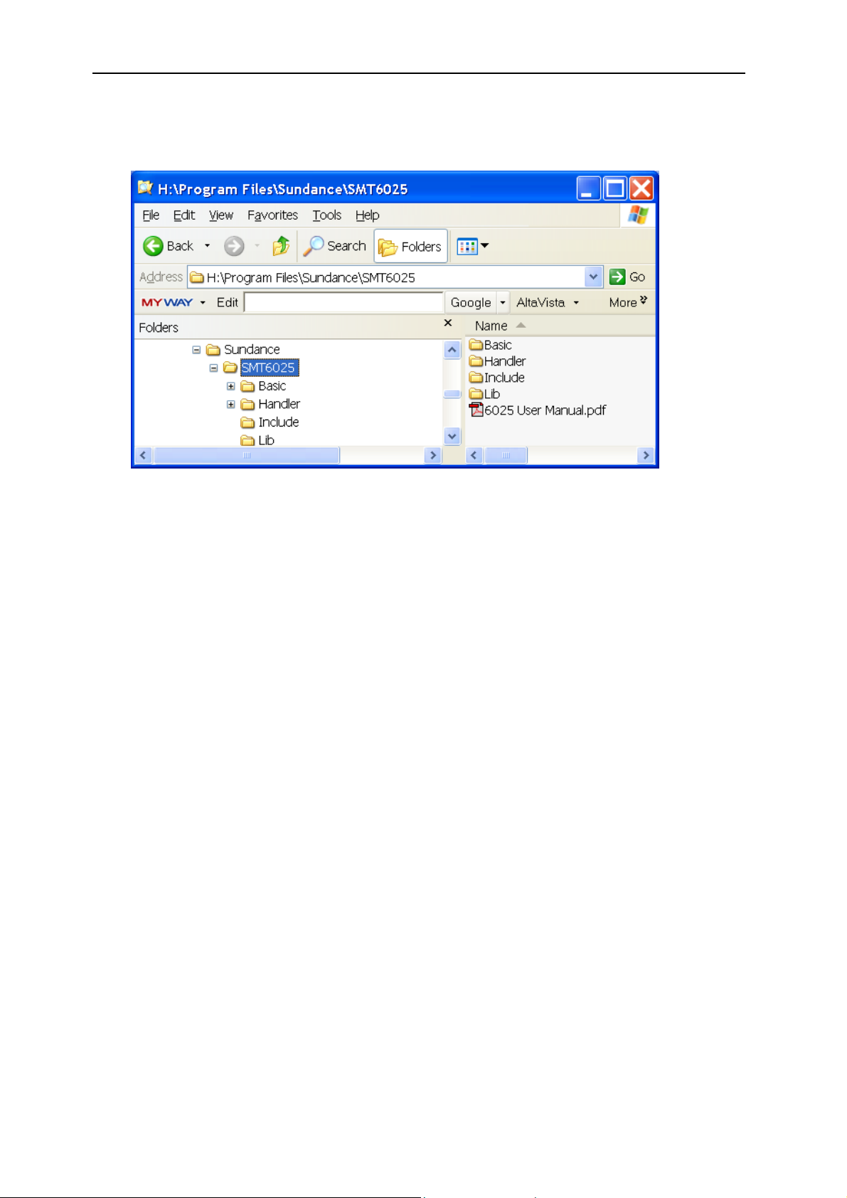
The default directory is “C:\Program Files\Sundance\SMT6025”. Installation
should give you the directory structure shown below.
Figure 2 - Directory structure after installing the SMT6025
Applications need access to smtdrv.h and smtdrv.lib. You need to arrange that
these files can be found during compilation and linking. We strongly recommend
that you do not make copies of these files, but access them from the installation
directory as follows:
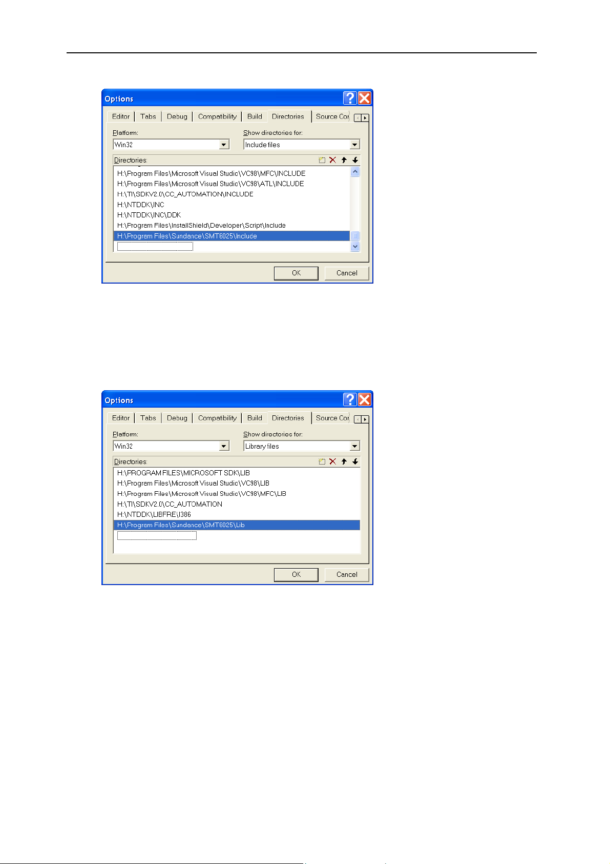
6.1 Configuring Visual Studio
The installation process configures the examples to compile and link correctly
without any user intervention. However, for your own applications, you need to
configure visual studio to add the paths to the include and lib directories to your
compiler options.
You do this as follows:
• Open Visual studio.
• Select "Tools->Options" from the menu.
• Select the “Directories” tab.
• Select “Include files” from the "Show directories for" drop down list.
• Add the path to the include directory for the SMT6025 installation to the
list of directories.
User Manual (QCF42); Version 2.9, 22/02/02; © Sundance Multiprocessor Technology Ltd. 2002
Page 9
Version 2.9 Page 9 of 45 SMT6025 User Manual
Figure 3 - Adding the path to the include directories to the compiler options
• Next select “Library files” from the "Show directories for" drop down list.
• Add the path to the library files for the SMT6025 to the to the list of
directories.
Figure 4 - Adding the path to the library directories to the compiler options
7 Design philosophy
The design of the SMT6025 allows developers to:
• Obtain a simple interface for controlling the host comport, Mailboxes, High
Speed Channel, and DSP interrupts.
• Access the low-level functionality of the hardware.
User Manual (QCF42); Version 2.9, 22/02/02; © Sundance Multiprocessor Technology Ltd. 2002
Page 10
Version 2.9 Page 10 of 45 SMT6025 User Manual
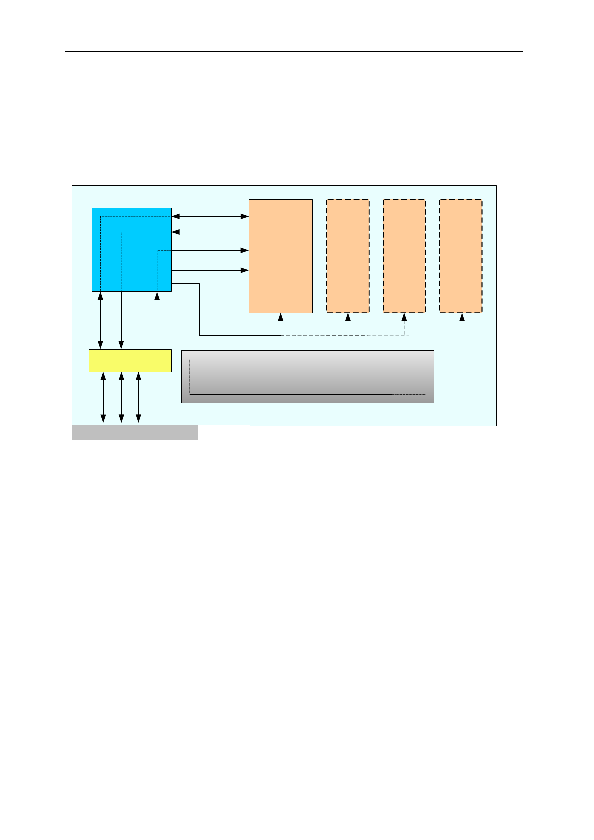
8 Hardware overview
You need to be aware of the assumptions the SMT6025 makes about hardware
resources. This section provides a basic overview of the main hardware features
and shows how the SMT6025 interacts with them. The carrier board’s User
Manual contains a more detailed description of the hardware.
CPLD (BAR 1)
Comport
IntD
PCI Bridge (BAR 0)
Comport
IntA
PCI
LINT (IIOF2)
Comport
IIOF1
IIOF2
IIOF0
Reset
The Bridge chip forms the link between the host and the DSP.
The mailbox registers are contained in the bridge chip.
TIM site 1
(Boot loader
supports
loading binary
files from
comport)
TIM site
2
TIM site
3
TIM site
4
Figure 5 - Overview of the hardware.
The figure above illustrates the main hardware concepts of a typical Sundance
carrier board.
8.1 Comport
A comport is a general mechanism for transferring data between components of
your system. Most TIM modules have several comports that can connect to
other TIMs or the host. These connections are usually made with FMS cables,
but some boards have built-in connections that can be controlled by carrier
board registers; the User Manual for your board will describe these registers in
detail. The standard board configuration will connect comport 3 on TIM site 1 to
the host.
8.2 The CPLD
The CPLD is used to configure the carrier board. It allows you to select the
direction of signals on the carrier board, select interrupt sources and set the
routing of the IIOF lines. The CPLD registers are mapped in BAR1 of the PCI
User Manual (QCF42); Version 2.9, 22/02/02; © Sundance Multiprocessor Technology Ltd. 2002
Page 11

Version 2.9 Page 11 of 45 SMT6025 User Manual
bridge chip. The carrier board’s User Manual gives more information about the
CPLD.
8.3 State of the IIOF lines
The LINT (local interrupt) line on the global bus side of the PCI bridge chip can
be switched to any of the IIOF lines that go to the DSP.
The initial configurations of the IIOF lines are as follows:
Line Use or direction
IIOF0 Host to DSP
IIOF1 DSP to Host
IIOF2 Used internally by the SMT6025 to signal mailbox interrupts
to the DSP.
Table 1 - Initial state of the IIOF lines when the SMT6025 starts up.
8.4 The PCI bridge chip
The bridge chip forms the link between the host and the carrier board. It
connects the local bus on the carrier board with the PCI bus of the host and
provides apertures that allow the local bus access to the PCI bus. These
apertures act like windows through which the local bus can access data on the
PCI bus.
The internal PCI bridge registers are mapped in BAR0, allowing access by both
the local bus (DSP side) and the PCI bus (host side). Contained in the bridge
chip are the 16 x 8-bit mailbox registers (Section 14).
The bridge chip provides a local bus interrupt line (LINT) as well as a PCI bus
interrupt line (IntA). These interrupt lines allow both the host and the DSP to
interrupt each other.
More information about the bridge chip can be found at
http://www.quicklogic.com
.
User Manual (QCF42); Version 2.9, 22/02/02; © Sundance Multiprocessor Technology Ltd. 2002
Page 12

Version 2.9 Page 12 of 45 SMT6025 User Manual
9 Software design
9.1 Interface mechanism
The design makes use of a C++ style interface pointer to the hardware.
SmtDrv.dll exports functions that gather information about the installed boards
and provide an interface pointer for later use.
To use the SMT6025, you need to:
• Obtain an interface pointer to the hardware by calling SmtOpenBoard().
• Use the interface pointer to call functions related to the hardware.
Example:
IFHw *pBoard = SmtOpenBoard(0); // open the first board found
pBoard->ResetTIMs();
pBoard->BinaryLoad("MyFile.app");
10 Functions exported by SmtDrv.dll
This section describes each of the functions exported by SmtDrv.dll. These
functions are described in the header file SmtDrv.h.
10.1 SmtOpen
Initialise the SMT6025 library. Applications must call this function before using
any other features of the library.
Prototype
SMTRet SmtOpen( void );
Return value
The function returns SMT_OK on successful completion; other return values
indicate failure. SmtGetError() can be used to translate error values into
descriptive strings.
10.2 SmtGetBoardCount
Return the number of Sundance carrier boards found in the system.
Prototype
Return value
DWORD SmtGetBoardCount(void);
The number of Sundance carrier boards found in the system.
User Manual (QCF42); Version 2.9, 22/02/02; © Sundance Multiprocessor Technology Ltd. 2002
Page 13

Version 2.9 Page 13 of 45 SMT6025 User Manual
10.3 SmtOpenBoard
Obtain an interface to a Sundance carrier board.
Prototype
IFHw * SmtOpenBoard( UINT nIndex );
Parameters
nIndex The zero based index of the carrier board. nIndex should
be in the range 0 <= nIndex < GetBoardCount().
Return value
The return value is an interface of type IFHw that can be used to access the
carrier board. Refer to section 11 for a description of the functions provided
by this interface. NULL (0) is returned on error.
10.4 SmtCloseBoard
Close an interface to a board. You should not use the interface pointer any
more after calling SmtCloseBoard().
Prototype
void SmtCloseBoard( UINT nBoard );
Parameters
nBoard The index of the board that should be closed. nIndex
should be in the range 0 <= nIndex < GetBoardCount().
10.5 SmtGetBoardIndex
Find the zero based index for the board at the specified base address.
Prototype
INT SmtGetBoardIndex( UINT nBaseAddress );
Parameters
nBaseAddress The board base address. The base address is the PCI
address that the host operating system has assigned to
the carrier board.
Return value
The zero based index of the board at base address nBaseAddress.
The function returns –1 when no board is found.
User Manual (QCF42); Version 2.9, 22/02/02; © Sundance Multiprocessor Technology Ltd. 2002
Page 14

Version 2.9 Page 14 of 45 SMT6025 User Manual
10.6 SmtGetBoardInfo
Return information about a carrier board. For a description of the information
returned see the remarks.
Prototype
SMTRet SmtGetBoardInfo( UINT nIndex, SMTBI& info );
Parameters
nIndex The zero based index of the board.
info The structure that is to be filled in with the board
information.
Return value
The function returns SMT_OK on successful completion; other return values
indicate failure. SmtGetError() can be used to translate error values into
descriptive strings.
Remarks
The information is returned in the SMTBI structure described below:
struct SMTBI {
SMTBoardType Type;
char cszType[32];
UINT nBase;
UINT nRange;
SMTHWStatus HwStatus;
SMTLock LockStatus;
SMTOpen OpenRes;
};
The information returned is summarized in the table below:
Field Description
Type Specify the type of carrier board.
cszType String description of the type of carrier board. For example
“SMT310Q”
nBase The PCI base address that the host operating system has assigned
to this carrier board.
nRange The number of bytes from the base address that has been assigned
to this carrier board.
HwStatus The hardware status of the carrier board. Valid values are SMT_On
and SMT_Off.
LockStatus If the carrier board could be opened successfully, this value will be
SMT_LOCK_OK.
User Manual (QCF42); Version 2.9, 22/02/02; © Sundance Multiprocessor Technology Ltd. 2002
Page 15

Version 2.9 Page 15 of 45 SMT6025 User Manual
OpenRes If the software was initialised correctly, this value will be
SMT_OPEN_OK.
10.7 SmtGetError
Return a string description the error value.
Prototype:
const char * SmtGetError( SMTRet Error );
Parameters:
Error The error value.
Return value:
A textual translation of the error value.
10.8 SmtGetDLLVer
Return the version information for SmtDrv.dll.
Prototype:
SMTRet SmtGetDLLVer( UINT &nMaj, UINT &nMin );
Parameters:
nMaj Receives the major version number.
NMin Receives the minor version number.
Return value:
The function returns SMT_OK on successful completion; other return values
indicate failure. SmtGetError() can be used to translate error values into
descriptive strings.
10.9 SmtGetPluginVersion
Return version information for the kernel mode plug-in.
Prototype:
void SmtGetPluginVersion( UINT &nMaj, UINT &nMin );
Parameters:
nMaj Receives the major version number.
NMin Receives the minor version number.
User Manual (QCF42); Version 2.9, 22/02/02; © Sundance Multiprocessor Technology Ltd. 2002
Page 16

Version 2.9 Page 16 of 45 SMT6025 User Manual
11 Functional description
Once an interface to the hardware has been obtained by calling
SmtOpenBoard(), the interface allows you to access the following features
available on various Sundance carrier boards.
Functionality SMT320-327 SMT300-310-310Q
Comport access Supported Supported
Downloading files Supported Supported
Mailboxes Not supported Supported
High speed channel Not supported Supported
Board state Supported Supported
Read and write carrier board registers Supported Supported
PCI bridge chip register access Supported Supported
DSP Interrupt Supported Supported
Table 2 - Supported functionality for Sundance carrier boards
12 Host comport
The simplest and most general I/O mechanism that can be used to communicate
between the host and the Root DSP is the host comport.
It is a sequential, bi-directional link that gives typical transfer speeds of up to
2MB/s. It is also used for loading programs into the DSP. Refer to the user
manual of your TIM for information about the supported file formats.
The functions used to transfer data over this link are blocking. This means that
they do not return until the transfer has completed. To force pending read or
write operation to complete by throwing an exception of the type SMTExc, use
CpCancel().
12.1 CpRead
Read data from the comport.
Prototype:
Parameters:
void IFHw::CpRead( void *pBuf, UINT nBytes )
pBuf Pointer to a buffer to receive the data read from the
comport.
User Manual (QCF42); Version 2.9, 22/02/02; © Sundance Multiprocessor Technology Ltd. 2002
Page 17

Version 2.9 Page 17 of 45 SMT6025 User Manual
nBytes The number of bytes to read from the comport.
12.2 CpWrite
Write data to the comport.
Prototype:
void IFHw::CpWrite( const void *pData, UINT nBytes )
Parameters:
pData Pointer to the buffer that contains the data to write to the
comport.
nBytes The number of bytes to write.
12.3 CpCancel
Cancel any pending comport operations. Pending operations are comport
operations that have been started but have not yet completed. For example:
Assume a thread is calling CpRead() and is waiting for the DSP to write some
data. Now assume that some other thread calls CpCancel(). In this case an
exception will be raised in the thread that started the operation CpRead()
operation. The exception will be of the type SMTExc.
Prototype:
void IFHw::CpCancel( void )
13 Downloading files
The host comport is the standard route for loading programs into your DSP
network.
Each TIM in your system will load a “bootloader” from its flash ROM when it
comes out of reset. This bootloader performs various housekeeping operations to
initialise the TIM and then waits until data arrives on any of it’s comports. The first
comport to become active is selected and the data it provides are loaded into the
DSP and executed. The host comport only gives you access to the Root TIM of
your DSP board. You must load any other TIMs in your system indirectly via the
root with explicit code. This is done automatically if you are loading a 3L Diamond
application.
13.1 BinaryLoad
The contents of the specified file will be sent down the host link unchanged, one
32-bit word at a time. Each 32-bit word is constructed from four bytes in the file,
the least significant byte coming first. This function is most commonly used to
load Diamond .app files that contain information allowing all processors in a
User Manual (QCF42); Version 2.9, 22/02/02; © Sundance Multiprocessor Technology Ltd. 2002
Page 18

Version 2.9 Page 18 of 45 SMT6025 User Manual
network to be loaded. It is important that the file you specify be a multiple of 4
bytes in size. If this is not the case, the function will round the size down to the
nearest four bytes, and remaining bytes will not be sent to the DSP.
Prototype:
void IFHw::BinaryLoad( const char *pcszFilename, PrgssInd
*pProgress = 0 )
Parameters:
pcszFilename The filename of the binary file to download to the Root
DSP.
pProgress Pointer to a structure that will obtain progress reports
during the download. If this value is zero, no progress is
reported.
13.2 CoffLoad
Load a COFF file to the Root DSP.
Prototype
void IFHw::CoffLoad( const char *pcszFilename,
const char *timtype,
PrgssInd *pProgress = 0 )
Parameters
pcszFilename The filename of the COFF file to be downloaded into the
Root DSP.
timtype The type of TIM as define in the file - Sundance.tim.
pProgress Optional pointer to a progress indication object.
14 Mailboxes
The mailboxes provided by the PCI bridge chip allow the host and the Root DSP
to signal each other with information.
Note that mailboxes are intended as a signalling mechanism and not as a way of
passing large amounts of data.
The V3 bridge chip provides 16 x 8-bit mailboxes. These mailboxes are
combined to form two independent 32-bit, bi-directional mailboxes. These
mailboxes are numbered 0 and 1.
User Manual (QCF42); Version 2.9, 22/02/02; © Sundance Multiprocessor Technology Ltd. 2002
Page 19

Version 2.9 Page 19 of 45 SMT6025 User Manual
SMT6025
Mailbox 0
Mailbox 1
PCI Bridge chip registers
Mb
Mb
MB1
Mb5
Mb9
10
Mb
14
13
Mb3
Mb7
Mb
11
Mb
15
MB2
Mb6
MB0
Mb4
Mb8
Mb
12
Figure 6 - Mailboxes with the SMT6025
IMPORTANT: Mailbox 1 is used internally by the HSC, leaving only Mailbox 0
available to user applications. See the HSC section 15.
The V3 bridge chip uses interrupts to notify both the PCI and the local bus side of
mailbox activity. The SMT6025 configures these interrupts to provide blocking
mailbox read and write functions on the host. These functions will block until the
DSP performs the required action. When the host side writes to a mailbox, the
write function will block (wait) until the DSP side had read the mailbox value.
Similarly when the host reads a mailbox, the function will block until the DSP
writes a mailbox value.
The host CPU usage is virtually zero during function blocking, as the blocking
behaviour of the mailbox functions is achieved by the use of interrupts.
Although you are free to develop your own mailbox code on the DSP side, we
recommend you use 3L Diamond © on the DSP side, as it provides built-in
support for the mailboxes.
14.1 MbWrite
Write a value to a mailbox.
Prototype
void IFHw::MbWrite( UINT nBox, DWORD dwValue )
Parameters
nBox The target mailbox. Must be zero.
dwValue The value to write to the mailbox.
User Manual (QCF42); Version 2.9, 22/02/02; © Sundance Multiprocessor Technology Ltd. 2002
Page 20

Version 2.9 Page 20 of 45 SMT6025 User Manual
14.2 MbRead
Read a value from a mailbox.
Prototype
DWORD IFHw::MbRead( UINT nBox )
Parameters
nBox The target mailbox. Must be zero.
14.3 MbCancel
Cancel a pending mailbox operation. The thread waiting on a pending mailbox
operation will throw an exception of the type SMTExc when MbCancel() is
called.
Prototype
void IFHw::MbCancel( UINT nBox )
Parameters
nBox The target mailbox. Must be zero.
User Manual (QCF42); Version 2.9, 22/02/02; © Sundance Multiprocessor Technology Ltd. 2002
Page 21

Version 2.9 Page 21 of 45 SMT6025 User Manual
15 High speed channel
A High-speed channel (HSC) is a powerful and simple way for the host and root
DSP to communicate. The SMT6025 provides 8 “High Speed Channels”.
15.1 Introduction
Communication across the HSC is always initiated by the DSP. The DSP
sends a control word, along with any associated data, to the host’s channel
handler, which performs some resulting action and replies with a reply word and
associated data. This is shown in the following diagram.
DSPHOST
Send associated data
Read command word
Read associated data
Perform required
operation
Write associated data
Write reply word
Channel handler
Send command word
TIME
Read reply word
Read associated data
Figure 7 - Standard HSC transaction
Each of the 8 HSC channels has an associated channel handler on the host.
The channel handler is responsible for acting on behalf of the DSP as shown in
Figure 7. There is a standard handler associated with each channel by default,
but the DSP can replace this with a user-defined handler.
User Manual (QCF42); Version 2.9, 22/02/02; © Sundance Multiprocessor Technology Ltd. 2002
Page 22

Version 2.9 Page 22 of 45 SMT6025 User Manual
15.2 Command word
A command word is a 32-bit value transmitted from the DSP to the host by
means of mailbox 1 (see section 14). The value is interpreted as an
HSC_WORD containing the following fields:
typedef struct {
UINT32 Data :25; // Data value
UINT32 Fn : 4; // Function code
UINT32 Channel : 3; // Channel selector
} HSC_WORD;
• Channel
The high-speed-channel number.
• Fn
A code indicating the function the host is to perform.
Value Function Description
0..1 Reserved
2 HSC_OpenHandler Open a handler
3 HSC_CloseHandler Close the current handler
4 HSC_CloseHostApp Close the host application
5 HSC_SramToHost Take SRAM data
6 HSC_HostToSram Give SRAM data
7 HSC_OpenPci Prepare for PCI memory transfers
8 HSC_ClosePci Terminate PCI memory transfers
9 HSC_PciToHost Write to PCI memory
10 HSC_HostToPci Read from PCI memory
11 HSC_UserDefined Perform user-defined function
11..15 Reserved
• Data field
A 25 bit unsigned value specific to the selected function.
User Manual (QCF42); Version 2.9, 22/02/02; © Sundance Multiprocessor Technology Ltd. 2002
Page 23

Version 2.9 Page 23 of 45 SMT6025 User Manual
15.3 Reply word
A reply word is a 32-bit value transmitted from the host to the DSP using
mailbox 1 (see section 14). The value is interpreted as an
HSC_WORD
containing the following fields:
typedef struct {
UINT32 Data :25; // Data value
UINT32 Fn : 4; // Function code
UINT32 Channel : 3; // Channel selector
} HSC_WORD;
• Channel
The number of the high-speed-channel to be used.
• Fn
A code indicating the host’s response to the original command.
Value Function Description
0 HSC_OK OK reply
1 HSC_Error Error reply
2..15 Reserved
• Data field
A 25 bit unsigned value containing optional error information.
15.4 Associated data
Some of the commands sent to the host have associated data that need to be
passed to the host. Similarly, the reply from the host may also include
associated data. This data is transmitted using either the carrier board’s SRAM
or the host memory.
15.4.1 Carrier board SRAM
Each HSC has an associated region of 64KB in the carrier board’s
SRAM, the argument area, to be used for transmitting associated data.
The DSP can read and write this memory using the global bus. The
carrier board’s SRAM is directly accessible in the host address space.
The
SMT6025 provides utility functions that allow the host to access the
argument area for each channel. Similarly, on the DSP side,
Diamond ©
provides utility functions with which you can access the
SRAM argument area.
3L
User Manual (QCF42); Version 2.9, 22/02/02; © Sundance Multiprocessor Technology Ltd. 2002
Page 24

Version 2.9 Page 24 of 45 SMT6025 User Manual
15.4.2 Host memory
The host can lock down a region of its memory and make this available
to the DSP over the PCI bus. The host memory needs to be locked
down in order for the DSP to safely gain access this memory. The host
places Information necessary for the DSP to access this memory in a
section of the carrier board’s SRAM reserved for this purpose. This
information is known as a memory descriptor list (MDL), and each MDL
can describe an area of host memory up to 16MB in size. There is one
MDL for each HSC.
The host operating system will not page to disk any locked down
memory, and will ensure that the memory remains at a fixed physical
location.
SRAM memory
Channel 0 MDL
Channel 1 MDL
64KB Area for
MDL
64KB SRAM
argument area
Channel 2 MDL
Channel 3 MDL
Channel 4 MDL
Channel 5 MDL
Channel 6 MDL
Channel 7 MDL
Figure 8 - Layout of the SRAM memory
Byte offset
0x00000
0x20000
0x40000
0x60000
0x80000
0xA0000
0xC0000
0xE0000
15.5 Channel handler
A channel handler is software that runs on the host and performs actions on
behalf of the DSP. Figure 9 describes the operation of a handler.
User Manual (QCF42); Version 2.9, 22/02/02; © Sundance Multiprocessor Technology Ltd. 2002
Page 25

Version 2.9 Page 25 of 45 SMT6025 User Manual
The DSP loads a handler by sending a command word to the host. Once the
handler is loaded, the DSP communicates directly with the handler.
Host application
(.exe)
Host
application
Host side handler (.dll)
Interface with
the DSP side
in some way
Receive
command
word
Perform
some action
Replay to
DSP
DSP application
(.app)
Send
command
Read reply
DSP sideHost side
Figure 9 - Operation of a handler
When the handler receives the DSP’s command word, it performs some action.
This action may or may not involve the host side software.
15.5.1 Handler not interfacing to host software
If the host side code is not involved in the handler, then the handler
performs actions on behalf of the DSP as and when told to do so by the
DSP. These actions occur without the knowledge of the host side
software. An example of this would be the HSCFile library where the
handler (a simple file system) simply performs actions on behalf of the
DSP.
15.5.2 Handler interfacing to host software
In some situations the host application may want to have an interface to
the loaded handler. In this case, the host and the DSP both share the
handler, and the host may wait for the DSP to perform some action to
establish synchronisation. An example of such a handler is the default
handler that is in operation if the DSP does not specifically load a
handler.
User Manual (QCF42); Version 2.9, 22/02/02; © Sundance Multiprocessor Technology Ltd. 2002
Page 26

Version 2.9 Page 26 of 45 SMT6025 User Manual
A number of functions allow the host application to interface with the
channel handler.
15.5.2.1 GetHandler
Obtain an interface to the currently active handler on a channel.
Prototype
HSCHndl * IFHw::GetHandler (UINT Channel)
Parameters
nChannel The channel for which to get the handler.
15.5.2.2 WaitHandler
Wait for the DSP to load a handler on the channel specified and then
obtain an interface to the handler.
Prototype
HSCHndl * IFHw:: WaitHandler (UINT Channel)
Parameters
nChannel The channel for which to get the handler.
15.5.2.3 WaitAnyHandler
Wait for the DSP to load a handler on any channel and then obtain
an interface to the loaded handler.
Prototype
HSCHndl * IFHw::WaitAnyHandler (void)
Parameters
None
15.5.2.4 WaitCloseApp
Wait for the DSP to send a HSC_CloseHostApp command to the
host. This command indicates that the host application should
terminate.
Prototype
void IFHw::WaitCloseApp (void)
Parameters
None
User Manual (QCF42); Version 2.9, 22/02/02; © Sundance Multiprocessor Technology Ltd. 2002
Page 27

Version 2.9 Page 27 of 45 SMT6025 User Manual
15.5.2.5 RecallHandlers
Recall any loaded handlers and puts the host into a state where it will
read commands from the DSP but do not perform any action. This is
useful if the host side software wants to disconnect the DSP and the
handler. The DSP will no longer be able to communicate with any
handlers. This state will remain in operation until the DSP is reset, in
which case the default handler will be reselected.
Prototype
void IFHw:: RecallHandlers (void)
Parameters
None
15.5.3 Implementing a handler
The handler takes the form of a DLL. Development is done with
Microsoft Visual Studio 6.0. A handler DLL must export the following
function:
extern "C" __declspec(dllexport) HSCHndl* OpenHandler(HSC
*pHsc, int Code, int Arg);
where
pHsc Is a pointer to the HSC object.
Code Is a value specified by the DSP.
Arg Is a value specified by the DSP.
extern "C" __declspec(dllexport) void
CloseHandler(HSCHndl *p )
where
p Is a pointer to the currenlty open handler.
To implement a handler, derive the handler class from
HSCHndl and
implement the following virtual functions.
struct HSCHndl {
virtual ~HSCHndl() {};
virtual int InitHandler (HSC *pHsc) = 0;
virtual int OnPciToHost (HSC *pHsc, HANDLE hCancel) = 0;
virtual int OnHostToPci (HSC *pHsc, HANDLE hCancel) = 0;
virtual int OnOpenPci (HSC *pHsc, HANDLE hCancel) = 0;
virtual int OnClosePci (HSC *pHsc, HANDLE hCancel) = 0;
virtual int OnSramToHost (HSC *pHsc, HANDLE hCancel) = 0;
virtual int OnHostToSram (HSC *pHsc, HANDLE hCancel) = 0;
virtual int OnUserDefined (HSC *pHsc, HANDLE hCancel) = 0;
};
User Manual (QCF42); Version 2.9, 22/02/02; © Sundance Multiprocessor Technology Ltd. 2002
Page 28

Version 2.9 Page 28 of 45 SMT6025 User Manual
Each virtual function shown above corresponds to a command word
from the DSP. The mapping is shown in the table.
Function Called when:
OnPciToHost When the DSP sends a HSC_PciToHost command.
OnHostToPci When the DSP sends a HSC_HostToPci command.
OnOpenPci When the DSP sends a HSC_OpenPci command.
OnClosePci When the DSP sends a HSC_ClosePci command.
OnSramToHost When the DSP sends a HSC_SramToHost command.
OnHostToSram When the DSP sends a HSC_HostToSram command.
OnUserDefined When the DSP sends a HSC_UserDefined command.
15.5.4 Opening a channel handler
When the DSP wishes to open a handler on the host, the DSP writes
the details of the handler in the SRAM argument area for the relevant
channel. It then sends a
The format of the data block required in the SRAM is described by the
following structure, which can be found in smthsc.h.
typedef struct {
int Code;
int Arg;
char Dll[128]; /* name of handler dll,
} HSC_Param_OpenHandler;
The DSP is free to specify values for Code and Arg. These values
might be interpreted on the host by the OpenHandler() function. The
design of these values is completely up to the designer.
15.5.5 Closing a handler
Once the DSP has finished using a handler, it sends a
HSC_CloseHandler command word to the host. This will make the
host unload the handler, and revert back to the default handler.
HSC_OpenHandler command to the host.
including .DLL */
15.5.6 Development guidelines
For each of the virtual functions described by the HSCHndl class, takes
a cancel event handle as a parameter. When these functions return,
they should return one of the following values:
HSC_HANDLER_OK
User Manual (QCF42); Version 2.9, 22/02/02; © Sundance Multiprocessor Technology Ltd. 2002
Page 29

Version 2.9 Page 29 of 45 SMT6025 User Manual
HSC_HANDLER_ERROR
HSC_HANDLER_CANCEL
.
The cancel event is used to indicate to the handler that it needs to
terminate. Whenever you wait for an event in the handler code, you
need to also wait for this cancel event. If the cancel event becomes
signalled, the handler needs to return immediately with the value
HSC_HANDLER_CANCEL.
Your handler code may look like this:
HANDLE h[] = {hCancel,hMyEvent};
DWORD dw = WaitForMultipleObjects( 2, h, FALSE,INFINITE);
if (dw == WAIT_OBJECT_0)
return HSC_HANDLER_CANCEL;
return HSC_HANDLER_OK;
15.6 The HSC object
The channel handler communicates with the DSP by means of an interface to a
HSC object. This object exposes the required high-speed-channel functionality.
15.6.1 GetIFHw
Obtain a pointer to the hardware interface of which this HSC object is
part.
Prototype
IFHw * HSC::GetIFHw( void )
Parameters
None
15.6.2 GetChannel
Return the channel number for this HSC object.
Prototype
UINT HSC::GetChannel( void )
Parameters
None
15.6.3 GetHandlerName
Get the name of the channel handler in operation.
User Manual (QCF42); Version 2.9, 22/02/02; © Sundance Multiprocessor Technology Ltd. 2002
Page 30

Version 2.9 Page 30 of 45 SMT6025 User Manual
Prototype
const char * HSC::GetHandlerName (void)
Parameters
None
15.6.4 PciOpen
Associate a region of host PCI memory space with a high-speed
channel.
Prototype
Void * HSC::PciOpen( UINT Bytes, void *pMem,
bool bLocked=false)
Parameters
Bytes The size of the memory pointed to by pMem.
pMem Points to the host memory that is to be associated
with this channel.
bLocked Specifies that the memory pointed to by pMem has
already been locked, and should not be unlocked
when the channel is closed later on.
15.6.5 PciClose
Disassociate the region of host PCI memory space previously
associated with this channel during the PciOpen() call. If the memory
has not been specified as locked, this function will unlock the memory.
Prototype
void HSC::PciClose( void )
Parameters
None
15.6.6 GetData
Return the data field value for the current DSP command word.
Prototype
UINT HSC::GetData (void)
Parameters
None
User Manual (QCF42); Version 2.9, 22/02/02; © Sundance Multiprocessor Technology Ltd. 2002
Page 31

Version 2.9 Page 31 of 45 SMT6025 User Manual
15.6.7 SetData
Set the data field value for the current reply word.
Prototype
void HSC::SetData (UINT n)
Parameters
n The data field value that is to be returned to the
DSP.
15.6.8 ArgsPut
Write data to the SRAM argument area for this high-speed-channel.
Prototype
void HSC::ArgsPut (UINT nBytes, void *pMem)
Parameters
nBytes Data size in bytes. The maximum size allowed is
64 KB
pMem Buffer to write.
Notes:
None
15.6.9 ArgsGet
Read arguments from the SRAM argument area for this high-speedchannel.
Prototype
void HSC::ArgsGet (UINT nBytes, void *pMem)
Parameters
nBytes Size of the buffer pointed to by pMem. The
pMem Pointer to the buffer that will receive the
Notes:
None
maximum size allowed is 64 KB
parameters from the SRAM..
User Manual (QCF42); Version 2.9, 22/02/02; © Sundance Multiprocessor Technology Ltd. 2002
Page 32

Version 2.9 Page 32 of 45 SMT6025 User Manual
15.7 The default handler
When no channel handler is specified, the default handler will be in operation.
This handler provides the basic functionality on the host side associated with a
HSC.
The default handler is defined by the
HscDflt structure (See HscDflt.h), and
provides a number of functions that are listed in the table below.
Function Purpose
SramPutSync Initiate a SRAM put operation. SRamPutDone Complete a SRAM put operation. SramGetSync Initiate a SRAM get operation. SramGetDone Complete a SRAM get operation. SramCancel Cancel a pending SRAM put or get operation. PciOpenSync Associate host memory with a HSC. PciCloseSync Dissociates host memory. PciPutSync Initiate a PCI put operation. PciPutDone Complete a PCI put operation. PciGetSync Initiate a PCI get operation. PciGetDone Complete a PCI get operation. PciCancel Cancel a pending PCI put or get.
15.7.1 SRamPutSync
Initiate a write to the SRAM arguments area of this HSC object.
Prototype
UINT HscDflt::SramPutSync (void)
Parameters
None
Return value
The number bytes actually asked for by the DSP.
15.7.2 SRamPutDone
Perform a write to the SRAM arguments area of this HSC object.
Prototype
void HscDflt::SramPutDone (UINT nBytes, void *pMem)
User Manual (QCF42); Version 2.9, 22/02/02; © Sundance Multiprocessor Technology Ltd. 2002
Page 33

Version 2.9 Page 33 of 45 SMT6025 User Manual
Parameters
nBytes The number of bytes to write to the SRAM
argument area.
pMem Points to buffer to be written to the SRAM
argument area.
Return value
None
15.7.3 SRamGetSync
Initiate a read from the SRAM arguments area of this HSC object.
Prototype
UINT HscDflt::SramGetSync (void)
Parameters
None
Return value
The number bytes actually offered for by the DSP.
15.7.4 SRamGetDone
Perform a read from the SRAM arguments area of this HSC object.
Prototype
void HscDflt::SramGetDone (UINT nBytes, void *pMem)
Parameters
nBytes The number of bytes to read from the SRAM
pMem Points to buffer to receive the SRAM argument
Return value
None
15.7.5 SramCancel
Cancel any pending SRAM put or get operations.
argument area.
data.
Prototype
Void HscDflt::SramCancel( void )
Parameters
None
User Manual (QCF42); Version 2.9, 22/02/02; © Sundance Multiprocessor Technology Ltd. 2002
Page 34

Version 2.9 Page 34 of 45 SMT6025 User Manual
15.7.6 PciOpenSync
This function locks and associates the memory specified with the HSC
object. This function blocks until the DSP sends a
HSC_OpenPci
command to the host.
Prototype
void * HscDflt::PciOpenSync (UINT Bytes, void *pMem,
bool bLocked=false)
Parameters
nBytes The size of the memory pointed to by pMem.
pMem Points to the host memory that is to be associated
with this channel.
bLocked Specifies that the memory pointed to by pMem has
already been locked, and should not be unlocked
when the channel is closed later on.
15.7.7 PciCloseSync
This function disassociates the host memory previously associated by
calling PciOpenSync(). This function blocks until the DSP sends a
HSC_ClosePci command to the host. This is used to synchronise the
controlled shutdown of the host side program.
Prototype
void HscDflt::PciCloseSync (void)
Parameters
None
15.7.8 PciPutSync
Initiate a write to the PCI memory for this high-speed-channel.
Prototype
UINT HscDflt::PciPutSync (void)
Parameters
None
Return value
15.7.9 PciPutDone
Complete a write to PCI memory operation for this HSC object.
Prototype
User Manual (QCF42); Version 2.9, 22/02/02; © Sundance Multiprocessor Technology Ltd. 2002
The number bytes actually asked for by the DSP.
Page 35

Version 2.9 Page 35 of 45 SMT6025 User Manual
void HscDflt::PciPutDone (UINT nBytes)
Parameters
nBytes The number of bytes that was actually transferred
to the PCI memory.
Return value
None
15.7.10 PciGetSync
Initiate a read from the PCI memory for this high-speed-channel.
Prototype
UINT HscDflt::PciGetSync (void)
Parameters
None
Return value
The number bytes actually offered by the DSP.
15.7.11 PciGetDone
Complete a read from the PCI memory operation for this HSC object.
Prototype
void HscDflt::PciGetDone (UINT nBytes)
Parameters
nBytes The number of bytes that was actually taken from
Return value
None
15.7.12 PciCancel
Cancel any pending memory read or write function. The thread that is
cancelled will throw an exception of the type SMTExc.
the PCI memory.
Prototype
void HscDflt::PciCancel( void )
Parameters
None
User Manual (QCF42); Version 2.9, 22/02/02; © Sundance Multiprocessor Technology Ltd. 2002
Page 36

Version 2.9 Page 36 of 45 SMT6025 User Manual
16 Board state
You usually need to reset the TIMs on the carrier board before downloading your
application.
16.1 ResetTIMs
Reset the TIMs on the carrier board.
Prototype
void IFHw::ResetTIMs(void)
16.2 ResetBoard
Reset the carrier board. This function resets the TIMs and the JTAG controller.
Prototype
void IFHw::ResetBoard(void)
17 Read and write carrier board registers
The SMT6025 gives you access to the carrier board’s registers to enable you to
perform any low level accesses that you might require.
Refer to the carrier board’s user manual for a description of the carrier board
registers and BAR address mapping.
The register access is specified by a BAR address and offset values.
For the following functions, the number at the end of the function name indicates
the number of bits that are to be read or written. For each function:
nBar BAR to use.
nOffset Offset into the BAR to access.
17.1 Read32
Read 32 bits from the address specified.
Prototype
DWORD IFHw::Read32( UINT nBar, UINT nOffset )
17.2 Read16
Read 16 bits from the address specified.
Prototype
DWORD IFHw::Read16( UINT nBar, UINT nOffset )
User Manual (QCF42); Version 2.9, 22/02/02; © Sundance Multiprocessor Technology Ltd. 2002
Page 37

Version 2.9 Page 37 of 45 SMT6025 User Manual
17.3 Read8
Read 8 bits from the address specified.
Prototype
DWORD IFHw::Read8( UINT nBar, UINT nOffset )
17.4 Write32
Write 32 bits to the address specified.
Prototype
void IFHw::Write32( UINT nBar, UINT nOffset, DWORD dword
17.5 Write16
Write 16 bits to the address specified.
Prototype
void IFHw::Write16( UINT nBar, UINT nOffset, WORD word )
17.6 Write8
Write 8 bits to the address specified.
Prototype
void IFHw::Write8( UINT nBar, UINT nOffset, BYTE byte )
18 PCI bridge chip register access
The Sundance carrier boards use a V3 bridge chip to interface to the PCI bus.
Certain resources are assigned to the carrier board when the host boots. These
resources include I/O address range, memory range and interrupt resources.
Information about these resources is kept in the PCI bridge chip registers.
The PCI bridge chip registers hold setup and control values and implement the
mailbox registers. Although direct access to the mailbox registers (offset 0XC0 –
0xCF) is possible, it is strongly recommended that you use the
in support (see section 14). This is a consequence of the design of the interrupt
service routine used by the
SMT6025.
A special bus cycle on the PCI bus is used to access the PCI registers of the
carrier board. This special bus cycle does not make use of the BAR mapping,
and is therefore safe to use even if the BAR addresses have not been set up.
SMT6025’s built-
You should not need direct access to the PCI registers for most systems. Please
make sure that you know what you are doing before accessing the PCI bridge
chip registers. Writing incorrect values to these registers will almost certainly
crash the host.
User Manual (QCF42); Version 2.9, 22/02/02; © Sundance Multiprocessor Technology Ltd. 2002
Page 38

Version 2.9 Page 38 of 45 SMT6025 User Manual
For a detailed description of the PCI bridge chip registers, refer to the user
manual for the bridge chip. http://www.quicklogic.com
.
The number at the end of the following function names indicates the number of
bits being read or written.
18.1 PciRead32
Read 32 bits from the PCI register specified.
Prototype
DWORD IFHw::PciRead32( DWORD dwReg)
18.2 PciWrite32
Write 32 bits to the PCI register specified.
Prototype
void IFHw::PciWrite32(DWORD dwReg, DWORD dwValue )
18.3 PciWrite16
Write 16 bits to the PCI register specified.
Prototype
void IFHw::PciWrite16( DWORD dwReg, WORD wValue )
18.4 PciWrite8
Write 8 bits to the PCI register specified.
Prototype
void IFHw::PciWrite8( DWORD dwReg, BYTE cValue )
18.5 PciVirtualAddr
Return the virtual memory address for the Base Address Region specified.
Prototype
void IFHw::PciVirtualAddr( UINT nBar, void *&pVirtAddr )
19 DSP interrupt
The DSP (C40) interrupt is a mechanism that was inherited from a previous
generation of carrier boards and is still supported in the current generation. The
DSP interrupt allows the DSP to interrupt the host.
The DSP can generate a DSP interrupt to the host by toggling the IIOF1 line.
User Manual (QCF42); Version 2.9, 22/02/02; © Sundance Multiprocessor Technology Ltd. 2002
Page 39

Version 2.9 Page 39 of 45 SMT6025 User Manual
The SMT6025 allows you to attach an interrupt function to this event. Unlike
mailboxes, no data is transferred with this type of interrupt.
Refer to the samples for the DSPInt interrupt sample.
19.1 DspAttatchInt
Attach a user-specified function that is to be called when a DSP interrupt
occurs.
Prototype
void IFHw::DspAttatchInt( PFN_DSP_INT pDSPIntFunc )
Parameters
pDSPIntFunc
Pointer to the function that is to be called when the DSP
interrupt occurs.
20 Memory allocation
You can make minor improvements in the performance of the HSC by using
contiguous memory. The following functions allow you to allocate such memory.
20.1 MemLock
Lock down a memory buffer. The function can be used to lock down a
contiguous or scatter-gather type buffer. In the case of a scatter-gather type
buffer, the user has to allocate the memory before calling this function.
Prototype
Void * IFHw:: MemLock( UINT nBytes, void *pBuf,
MDLEntry * pEntries, UINT &nEntCnt)
Parameters
nBytes
The size of the memory. For scatter-gather memory, this
specifies the size of the memory pointer to by pBuf. For
contiguous memory, this specifies the required memory
size.
pBuf
For scatter gather memory, this points to the memory.
For contiguous memory, this needs to be zero.
pEntries Optional pointer to a buffer to receive the memory
descriptor list (MDL). When this value is zero, no MDL
list is returned .
nEntCnt This is both an input and an output parameter. As an
input parameter, this indicate the number of MDL entries
that pEntries buffer contains. When the function returns,
User Manual (QCF42); Version 2.9, 22/02/02; © Sundance Multiprocessor Technology Ltd. 2002
Page 40

Version 2.9 Page 40 of 45 SMT6025 User Manual
the variable contains the actual number of MDL entries
used to describe the memory locked.
Return value
The function returns a pointer to the locked down memory, or zero on
failure. The function may fail if you are requesting the MDL list, but do not
provide enough storage for all the MDLs required to describe the locked
down memory. In this case, nEntCnt will contain the number of MDL entries
required to describe the memory.
20.2 MemUnlock
Free a contiguous region of memory that was previously allocated by a call to
MemLock().
Prototype
void IFHw::MemUnlock( void *pMem )
Parameters
pMem
Pointer to the memory to unlock.
21 Performance figures
The table below shows typical performance figures obtained with the SMT6025.
Transfer type Read [MB/s] Write [MB/s]
HSC with contiguous memory. 46 40
HSC with Scatter/Gather memory. 40 32
Host comport 2 2
Table 3 - Typical performance figures for various transfer types
22 Handling errors
22.1 Exported functions
Most of the functions exported by SmtDrv.dll return status values. You should
always check the return values from these functions. SmtGetError() can be
used to translate the return values into text strings.
The following is a sample segment to show how to use the functions exported
by SmtDrv.dll.
User Manual (QCF42); Version 2.9, 22/02/02; © Sundance Multiprocessor Technology Ltd. 2002
Page 41

Version 2.9 Page 41 of 45 SMT6025 User Manual
// Open the library
SMTRet ret = SmtOpen();
if ( ret!=SMT_OK )
{
cout << "Could not open SmtDrv library. The error was ("
<< SmtGetError(ret)
<< ")"
<< endl;
return 0;
}
22.2 Exception mechanism
The functions accessed through the SmtOpenBoard() interface will signal errors
by throwing an exception of type SMTExc. Any of the functions provided by
IFHw may throw an exception of type SMTExc.
You need to surround your function accesses by a try-catch block as shown:
try
{
pB->ResetTIMs();
pB->BinaryLoad( "..\\DSP\\Dsp335.app" );
}
catch( SMTExc &e )
{
cout << "An exception occured. ("
<< e.GetError()
<< ")"
<< endl;
}
Your program will be terminated with an un-handled exception dialog should
you fail to catch the exception.
23 Extras
A separate DLL (SmtUI.dll) supplies common user interface functionality. This
DLL contains the most often used, general-purpose dialogs and can make life
easier for developers.
To use SmtUI.dll you need to include SmtUI.h in your source and then link to
SmtUI.lib. See the sample for more detail.
To obtain an interface to the SmtUI DLL, you call Smt_UIOpen().
User Manual (QCF42); Version 2.9, 22/02/02; © Sundance Multiprocessor Technology Ltd. 2002
Page 42
Version 2.9 Page 42 of 45 SMT6025 User Manual
Example:
IF_UI * p = Smt_UIOpen();
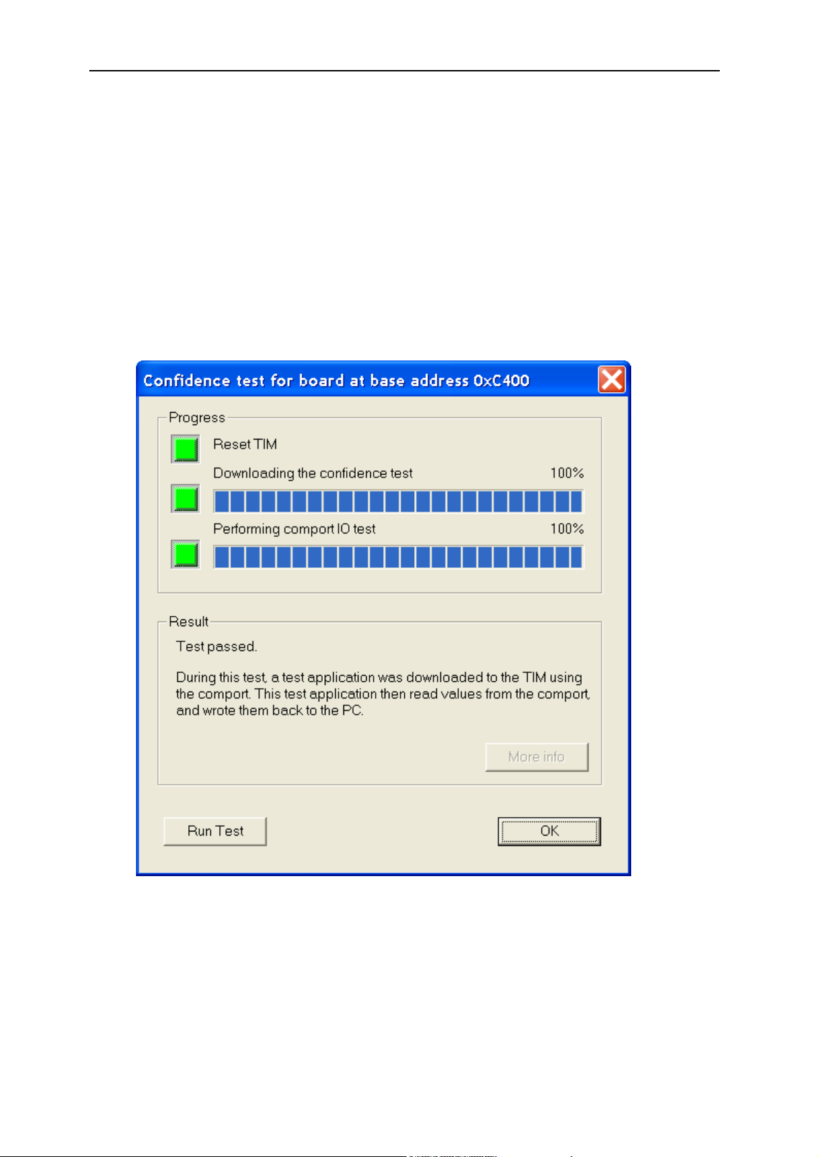
23.1 Confidence test dialog
The confidence test dialog is the same dialog that is found in the
SmtBoardInfo.exe application. You may want to allow access to this dialog at
some point in your application to allow users to check that the hardware is
functioning properly.
Figure 10 - Confidence test dialog
To display this dialog:
#include “SmtUI.h”
User Manual (QCF42); Version 2.9, 22/02/02; © Sundance Multiprocessor Technology Ltd. 2002
Page 43

Version 2.9 Page 43 of 45 SMT6025 User Manual
#include “SmtDrv.h”
IFHw *pHw = SmtOpenBoard(0);
IF_UI * p = Smt_UIOpen();
p->SmtConfidenceTest( pHw );
23.2 SMT310Q comport switching dialog
It is possible to configure the comport connections between TIM sites on an
SMT310Q by writing a value to the on-board registers. See the SMT310Q User
Manual for more information. The dialog shown below allows users to set the
comport switches.
The comport switch register is volatile and need to be set each time the board is
powered up. The “Restore switch settings automatically” setting indicates that
any application making use of SmtDrv.dll (
SMT6025) will automatically set the
comport switches back to their previous values each time it runs.
Figure 11 - The SMT310Q comport switch dialog
User Manual (QCF42); Version 2.9, 22/02/02; © Sundance Multiprocessor Technology Ltd. 2002
Page 44

Version 2.9 Page 44 of 45 SMT6025 User Manual
To display this dialog:
#include “SmtUI.h”
#include “SmtDrv.h”
IFHw *pHw = SmtOpenBoard(0);
IF_UI * p = Smt_UIOpen();
p->ShowComportSwitch( pHw );
23.3 PCI Information dialog
This dialog displays the PCI devices found in the system and, for each of the
devices, the hardware resources associated with that device.
Figure 12 - The PCI information dialog
To display this dialog:
User Manual (QCF42); Version 2.9, 22/02/02; © Sundance Multiprocessor Technology Ltd. 2002
Page 45

Version 2.9 Page 45 of 45 SMT6025 User Manual
#include “SmtUI.h”
#include “SmtDrv.h”
IF_UI * p = Smt_UIOpen();
p-> SmtShowPCIInfo();
User Manual (QCF42); Version 2.9, 22/02/02; © Sundance Multiprocessor Technology Ltd. 2002
 Loading...