

Page 1

SMT6012
User Manual Version 4.6
User Manual (QCF42); Version 4.6, 26/06/02; © Sundance Multiprocessor Technology Ltd. 2002
Page 2

Version 4.6 Page 2 of 22 SMT6012 User Manual
Table of Contents
List of abbreviations................................................................................................................................................ 3
1 List of figures ................................................................................................................................................ 4
2 Introduction ................................................................................................................................................... 5
3 System requirements ..................................................................................................................................... 6
3.1 Software ................................................................................................................................. 6
3.2 Hardware................................................................................................................................ 6
4 Debug configurations .................................................................................................................................... 7
5 Software Installation and Setup..................................................................................................................... 8
5.1 Driver directory structure........................................................................................................ 8
5.2 Determining the I/O address of your carrier board ................................................................ 8
5.3 Setting up code composer studio version 2.x ........................................................................ 8
5.4 Setting up Code Composer Studio version 1.2.................................................................... 14
5.5 Setting up Code Composer Studio version 1.0.................................................................... 17
5.6 Setting up Code Composer version 4.3 ............................................................................... 18
6 Master/Slave configuration.......................................................................................................................... 19
7 Problematic configurations.......................................................................................................................... 20
7.1 Using C4x type processors with Code Composer Studio .................................................... 20
7.2 Code Composer Studio setup for mixed C62-C67 configuration......................................... 21
7.3 Code Composer Studio Setup for multiple carrier boards ................................................... 21
7.4 Mixed C4x/C6x Configuration .............................................................................................. 21
7.5 Using a C6x to program a C4x (Hex Loader)....................................................................... 22
8 Trouble Shooting......................................................................................................................................... 22
8.1 Using Code Composer and Code Composer Studio: .......................................................... 22
9 Known Issues .............................................................................................................................................. 22
9.1 Code Composer Studio........................................................................................................ 22
9.1.1 Exit ...................................................................................................... 22
User Manual (QCF42); Version 4.6, 26/06/02; © Sundance Multiprocessor Technology Ltd. 2002
Page 3
Version 4.6 Page 3 of 22 SMT6012 User Manual
List of abbreviations
CC Code Composer
CCS Code Composer Studio
cPCI Compact PCI
DSP Digital signal processor
EPK Emulation porting kit
PCI Peripheral Component Interconnect
SMT Sundance Multiprocessor Technology Ltd.
TIM Texas Instruments Module
User Manual (QCF42); Version 4.6, 26/06/02; © Sundance Multiprocessor Technology Ltd. 2002
Page 4

Version 4.6 Page 4 of 22 SMT6012 User Manual
1 List of figures
Figure 1 - JTAG Chain................................................................................................ 7
Figure 2 - Directory structure of CC and CCS drivers................................................. 8
Figure 3 - Selecting the standard XDS driver ............................................................. 9
Figure 4 - Specifying the driver configuration file...................................................... 10
Figure 5 - Setting the I/O Port address. .................................................................... 11
Figure 6 - Specifying the processors ........................................................................ 12
Figure 7 - Specifying the GEL file ............................................................................. 13
Figure 8 - Multiple independent boards .................................................................... 14
Figure 9 - Selecting the standard XDS driver ........................................................... 14
Figure 10 - Setting the I/O Port address to 0xE........................................................ 15
Figure 11 - Specifying the processors ...................................................................... 16
Figure 12 - Master/Slave configuration..................................................................... 19
Figure 13 - CCS setup for the sample configuration................................................. 20
Figure 14 - Example setup for mixed C4x and C6x processors................................ 21
Figure 15 - Using a C6x and a C4x processor on the same carrier board................ 21
User Manual (QCF42); Version 4.6, 26/06/02; © Sundance Multiprocessor Technology Ltd. 2002
Page 5
2 Introduction
The SMT6012 provides the drivers required to use Code Composer (CC) and Code
Composer Studio (CCS) with the following Sundance Multiprocessor Technology
range of carrier boards:
Texas Instruments software, if purchased through Sundance, will include the
SMT6012.
Sundance carrier board Description
SMT300 Single TIM cPCI carrier board
SMT300Q 4 TIM cPCI carrier board
SMT310 Single TIM PCI carrier board
SMT310Q 4 TIM PCI carrier board
SMT320 (Obsolete) 4 TIM PCI carrier board
SMT327 (Obsolete) 4 TIM cPCI carrier board
Table 1 - Sundance hardware supported by the SMT6012
The SMT300, SMT300Q, SMT310 and SMT310Q carrier boards all use the driver for
the SMT310. Similarly, the SMT320 and SMT327 both use the driver for the
SMT320. For the remainder of this document, SMT310 will refer to the SMT300,
SMT300Q, SMT310 and the SMT310Q. The SMT320 will refer to the SMT320 and
the SMT327.
If you are using a SMT320, check to make sure which version of the SMT320 you are
using. The version number of a SMT320 is written on the PCB, near the blue handle
and next to the serial number (ADC4-xxxx).
This document describes how to select a CC or CCS driver based on:
• The carrier board you use.
• The version of CC or CCS.
• On-board or off-board debugging requirement.
User Manual (QCF42); Version 4.6, 26/06/02; © Sundance Multiprocessor Technology Ltd. 2002
Page 6
Version 4.6 Page 6 of 22 SMT6012 User Manual
You need to have at least the following version of CC or CCS installed.
Processor type CC or CCS version required
C4x CC version 4.3
C6x CCS version 1.0 or higher (The FULL VERSION, not the
limited version supplied with an evaluation board).
3 System requirements
3.1 Software
• The PC Operating System must be Windows 9x / NT 4.0 / Windows 2000 or
above.
• On a Windows NT / Windows 2000/ XP system, you must be logged in as a
user with administrative rights.
3.2 Hardware
• The PC must supply 3.3V on the PCI bus. If you are not sure, please check
the voltage between a mounting hole of your carrier card And a Ground from
a PC power cable. Only a few C4x TIMs do not require 3.3V.
• Ensure that the bolt makes contact with the metal ring of the mounting hole.
See the user manual of your carrier board for the details.
User Manual (QCF42); Version 4.6, 26/06/02; © Sundance Multiprocessor Technology Ltd. 2002
Page 7
Version 4.6 Page 7 of 22 SMT6012 User Manual
4 Debug configurations
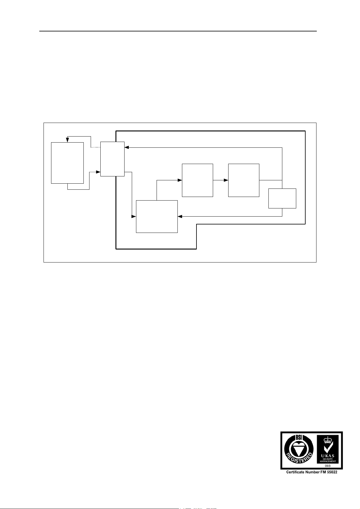
The Sundance carrier board includes a JTAG controller chip. This chip enables the
various processor elements on the carrier board to communicate information
between each other.
CC and CCS uses the JTAG chain to debug processors. The JTAG chain
interconnects hardware elements as shown in Figure 1 - JTAG Chain.
TDI
External
JTAG chain
TDO
Off-board
JTAG
connector
TDO
TDI
TDO
JTAG Controller
TDI Off-
board
TDI On-
board
TDI TDITDO TDO
DSP 1 DSP 2
On-board
JTAG
connectors
Sundance Carrier Board
Figure 1 - JTAG Chain
On-board and off-board debugging refers to the way the JTAG chain is used.
For on-board debugging the JTAG chain is local to the carrier board. The JTAG
controller selects the input from the “TDI On-board” pin. This effectively disables
the external JTAG chain.
For Off-board debugging, the JTAG controller chip selects its input from the
external connector. This implies that the JTAG chain now includes the external
JTAG chain. This configuration is useful when you want to debug external
hardware using the carrier board as a master.
If you are connecting the carrier board to other carrier boards located in the same
system, you can use the on-board JTAG connector to make their JTAG paths part
of the JTAG chain of the master carrier board.
Please refer to the user manual of the carrier board that you are using for the
details on how to connect the carrier board with an external JTAG chain.
CCS detects the carrier board with the highest I/O address first. On each of the
carrier boards, the processor in TIM site 1 is detected first and then the processor
on TIM site 2 etc.
User Manual (QCF42); Version 4.6, 26/06/02; © Sundance Multiprocessor Technology Ltd. 2002
Page 8
Version 4.6 Page 8 of 22 SMT6012 User Manual
5 Software Installation and Setup
Insert the SMT6012 CD into your CD drive. If the setup program does not start
automatically, then open explorer, browse to the CD and run Setup.exe.
5.1 Driver directory structure
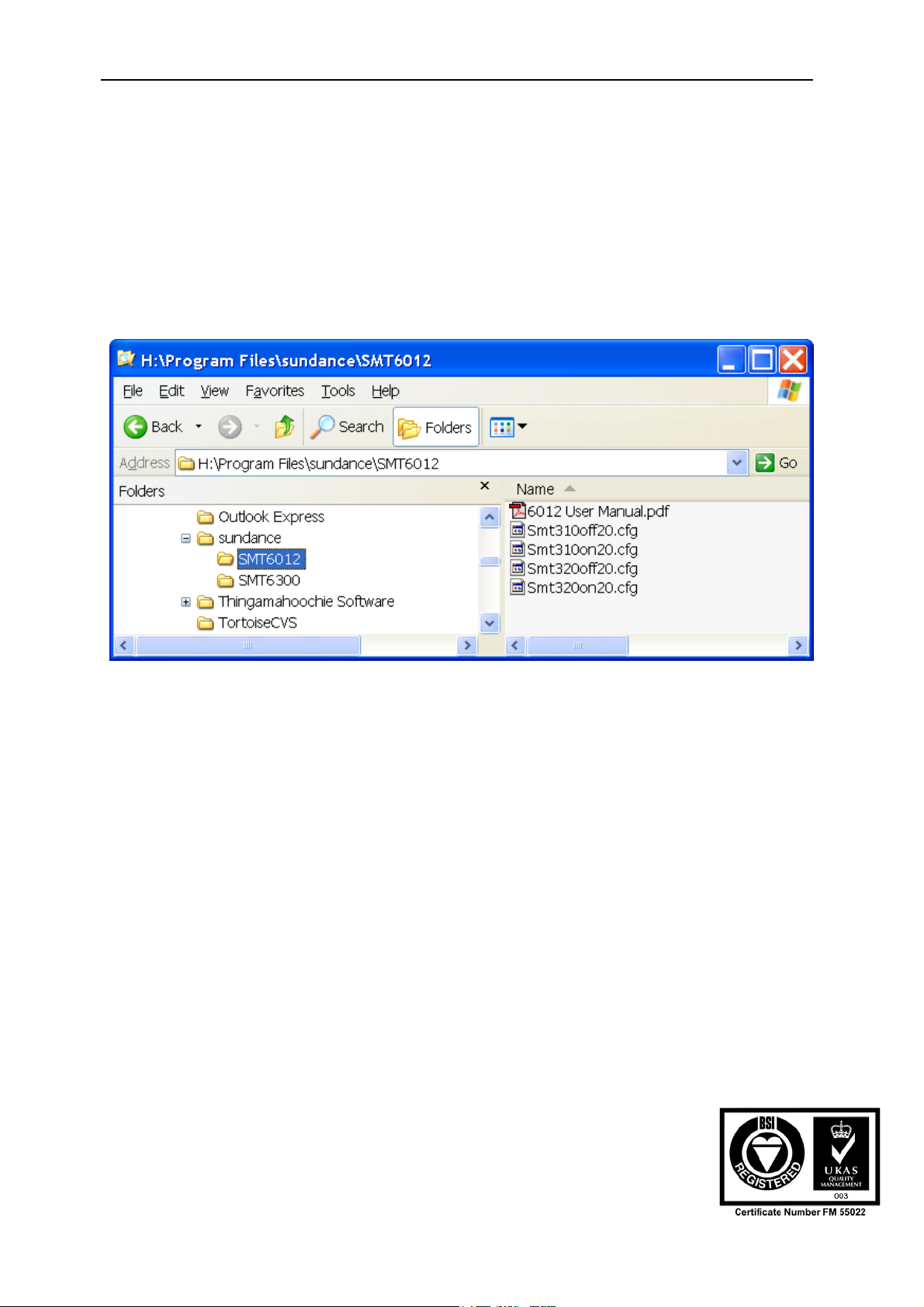
The CC and CCS drivers are installed to your PC under the “..\System32” directory.
During the setup of CC or CCS, you will need to refer to these drivers. For CCS
version 2.x the .cfg files needed to set up CCS are installed as shown in the figure.
Figure 2 - Directory structure of CC and CCS drivers
5.2 Determining the I/O address of your carrier board
After installing the SMT6012 software, you will need to find the base I/O address of
the Sundance carrier board. This address is required to set-up CC or CCS. You can
use the SMTBoardInfo.exe application that is supplied along with the SMT6300
software.
5.3 Setting up code composer studio version 2.x
• Run the Code Composer Setup program. Select the “Install a device driver”
link on the right hand side window. Browse to the driver’s directory under your
CCS directory. This is normally “C:\ti\drivers”. Next select the relevant XDS
driver file. The driver file you select will depend on the specifics of the DSP
you have. (For C62 and C67 type processors, this is typically the
“tixds6000.drv” and for C64 processors it is typically "tixds6400.drv".) Refer
to the TI documentation for which driver to use. Note that the
User Manual (QCF42); Version 4.6, 26/06/02; © Sundance Multiprocessor Technology Ltd. 2002
Page 9

Version 4.6 Page 9 of 22 SMT6012 User Manual
driver you should use may depend on the silicon rev of the processor you are
using.
• Note: For illustrative purposes only, we are using the "tixds6000.drv" file.
Figure 3 - Selecting the standard XDS driver
• In the “Device driver properties” window, click OK.
• In the “Available Boards/ Simulator types” window, double-click the relevant
driver file.
User Manual (QCF42); Version 4.6, 26/06/02; © Sundance Multiprocessor Technology Ltd. 2002
Page 10
Version 4.6 Page 10 of 22 SMT6012 User Manual
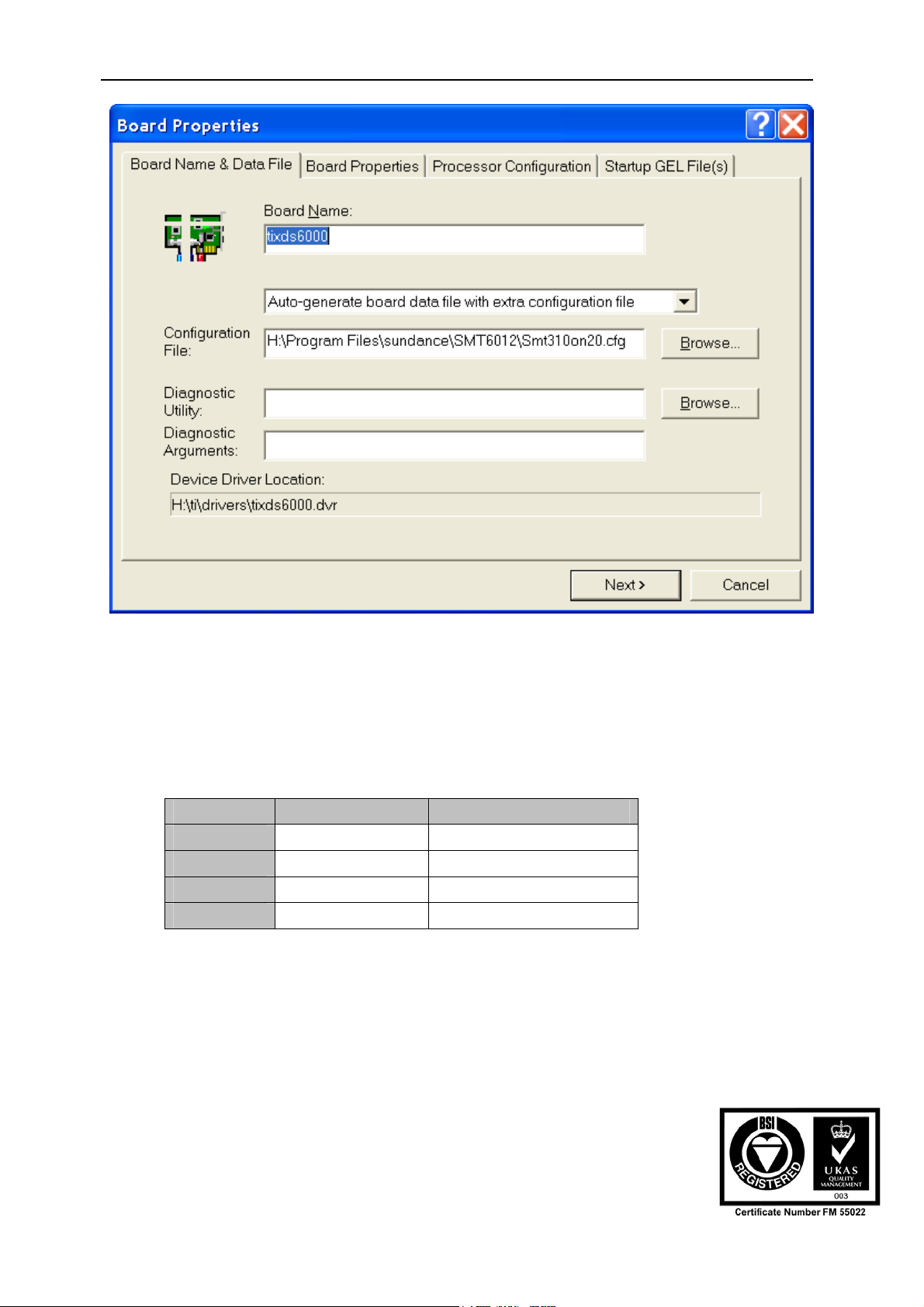
Figure 4 - Specifying the driver configuration file
• Select the “Auto-generate board data file with extra configuration file”. Select
“Browse” to browse to the directory where the SMT6012 is installed. This is
normally “C:\Program Files\Sundance\SMT6012”. Refer to the table below for
the relevant configuration file for your board. Click “Next”.
Board On-board Off-board
SMT310
SMT310Q
SMT320-V4
SMT320-V3
Table 2 – CCS 2.0 driver configuration file selection
SMT310On20.cfg SMT310Off20.cfg
SMT310On20.cfg SMT310On20.cfg
SMT320On20.cfg SMT320Off20.cfg
SMT320On20.cfg SMT320Off20.cfg
User Manual (QCF42); Version 4.6, 26/06/02; © Sundance Multiprocessor Technology Ltd. 2002
Page 11

Version 4.6 Page 11 of 22 SMT6012 User Manual
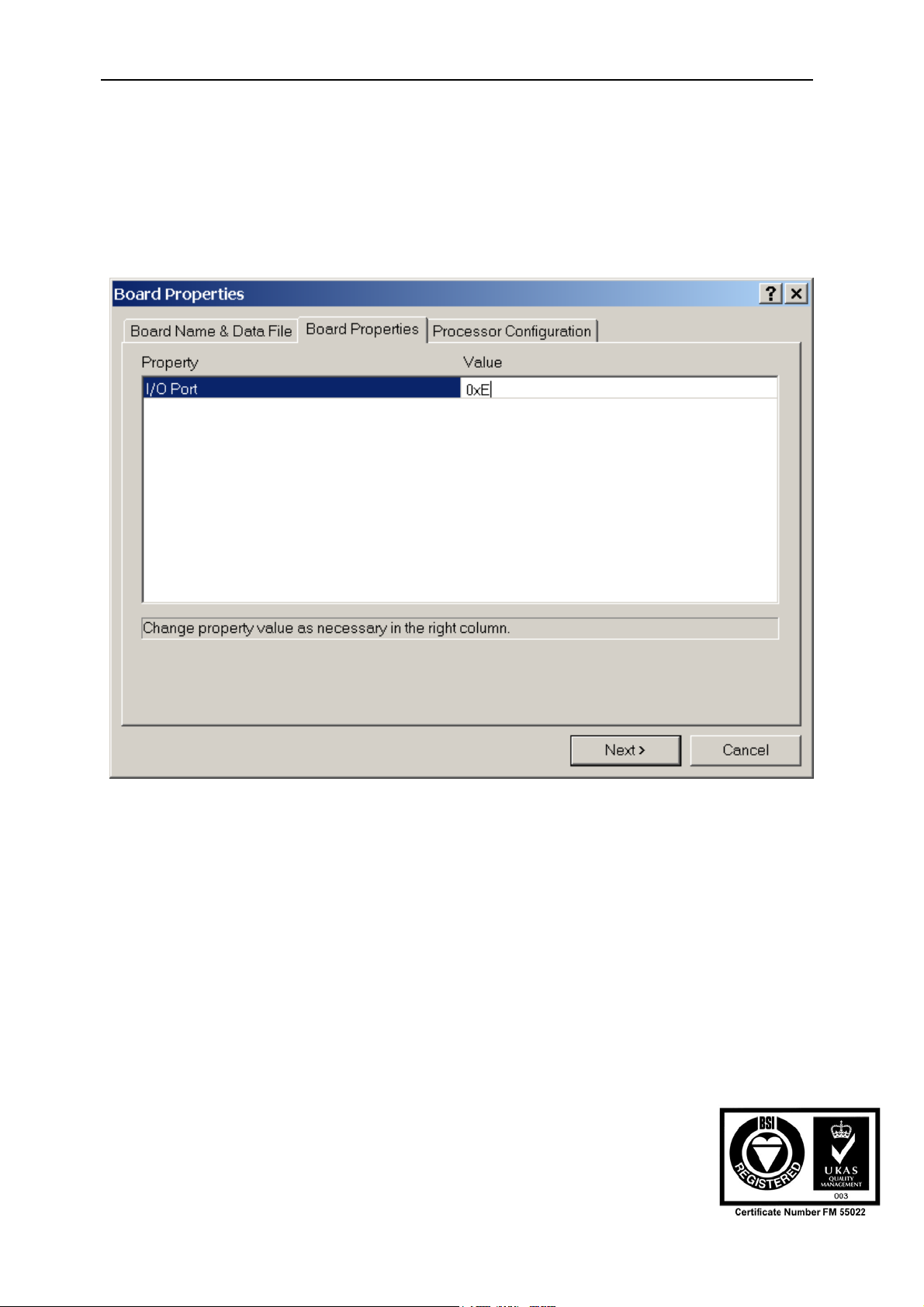
Figure 5 - Setting the I/O Port address.
• Now change “Value” to the I/O Port address that can be determined with the
SMTBoardInfo.exe application. Click “Next”.
User Manual (QCF42); Version 4.6, 26/06/02; © Sundance Multiprocessor Technology Ltd. 2002
Page 12
Version 4.6 Page 12 of 22 SMT6012 User Manual
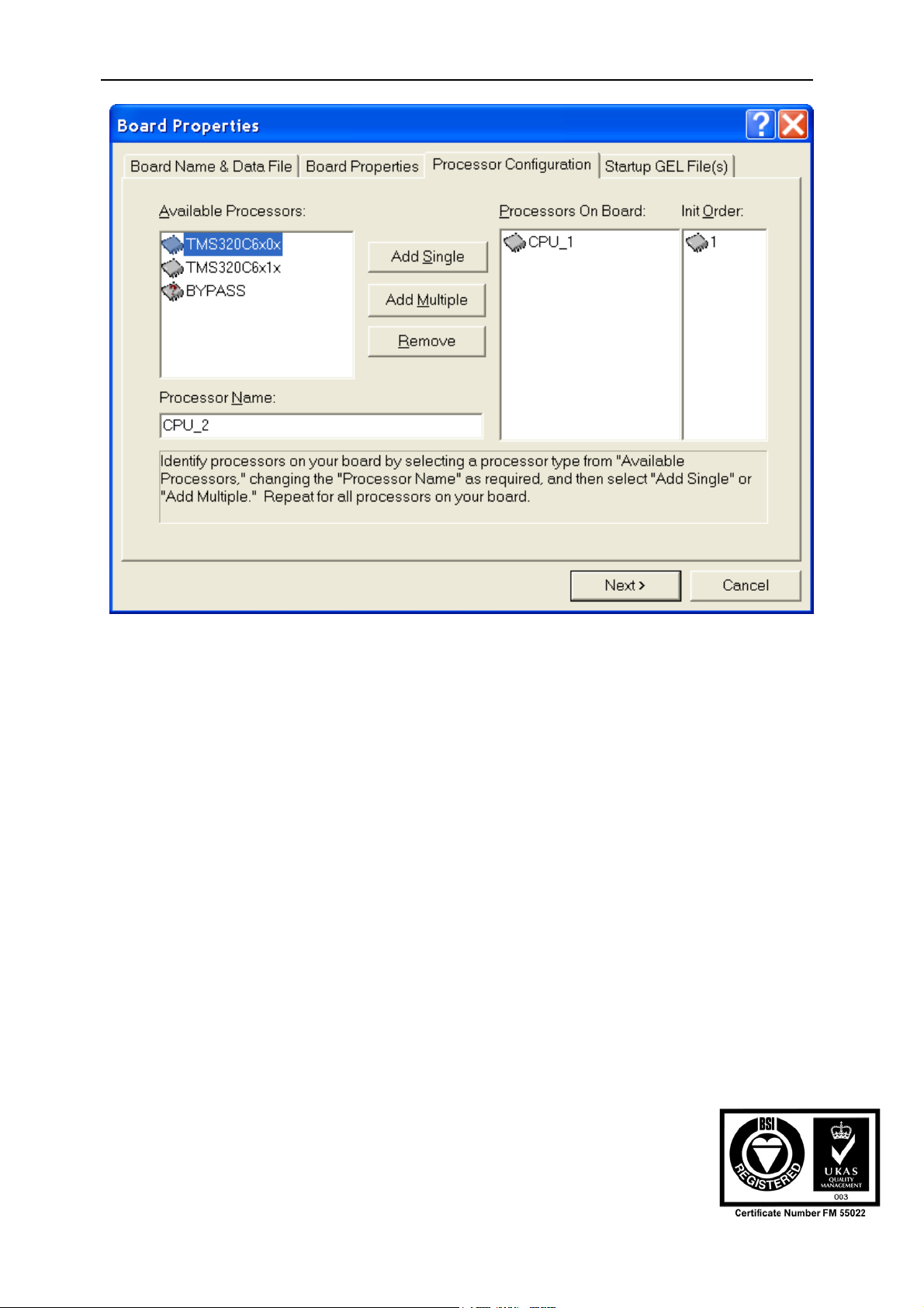
Figure 6 - Specifying the processors
• Select the processors that you have on your carrier board. If you have any
C4x processors, they need to be specified as “Bypass” with “Number of bits in
the instruction register” set to 8.
• Click “Next”
User Manual (QCF42); Version 4.6, 26/06/02; © Sundance Multiprocessor Technology Ltd. 2002
Page 13

Version 4.6 Page 13 of 22 SMT6012 User Manual
Figure 7 - Specifying the GEL file
• If you are using a GEL file, you can specify it at this stage.
• Click on “Finish”
• Save and exit the CCS 2.x setup program.
• You are now ready to run CCS 2.x
Note that If you are using multiple independent boards (i.e. boards that are not
connected via the JTAG chain) you should have a board entry for each of the boards.
This is not possible in CCS 1.2 to specify 2 independent boards, and you will have to
use CCS 2.x to accomplish this.
You can add more carrier boards to the system by repeating the procedure outlined
above. For each board you add, specify a unique board name.
The figure below shows the configuration for CCS 2.x for multiple independent
boards.
User Manual (QCF42); Version 4.6, 26/06/02; © Sundance Multiprocessor Technology Ltd. 2002
Page 14

Version 4.6 Page 14 of 22 SMT6012 User Manual
Figure 8 - Multiple independent boards
5.4 Setting up Code Composer Studio version 1.2
• Run the Code Composer Setup program. Select the “Install a device driver”
link on the right hand side window. Browse to the drivers directory under your
Code Composer directory and for the C62 and C67 type processors, select
the “tixds6000.drv” file as shown in Figure 9. This is typically “C:\ti\drivers”.
Figure 9 - Selecting the standard XDS driver
• In the “Device driver properties” window, click OK.
User Manual (QCF42); Version 4.6, 26/06/02; © Sundance Multiprocessor Technology Ltd. 2002
Page 15
Version 4.6 Page 15 of 22 SMT6012 User Manual
• In the “Available Boards/ Simulator types” window, double-click the “tixds6000”
driver.
• Click “Next”
Figure 10 - Setting the I/O Port address to 0xE
• Now change “Value” to 0xE as shown above, and click “Next”.
User Manual (QCF42); Version 4.6, 26/06/02; © Sundance Multiprocessor Technology Ltd. 2002
Page 16

Version 4.6 Page 16 of 22 SMT6012 User Manual
Figure 11 - Specifying the processors
• Select the processors that you have on your carrier board. If you have any
C4x processors, they need to be specified as “Bypass” with “Number of bits in
the instruction register” set to 8.
• Click on “Finish”
• Save and exit the CCS 1.2 setup program.
For Windows NT4/2000
• Add the following lines to your Windows NT environment. To do this, right
click on “My Computer” on the desktop, and select properties. Go to the
advanced tab and select “Environment variables”.
UNIFY_PODDRVR_E DLLNAME
UNIFY_PODPORT_E ADDRESS
User Manual (QCF42); Version 4.6, 26/06/02; © Sundance Multiprocessor Technology Ltd. 2002
Page 17

Version 4.6 Page 17 of 22 SMT6012 User Manual
For Windows 95/98
• Add the following entries in your “Autoexec.bat” file.
SET UNIFY_PODDRVR_E = DLLNAME
SET UNIFY_PODPORT_E = ADDRESS
• Where DLLNAME is the driver DLL name as described in the table below. For
example, SMT310On12.DLL. ADDRESS is the I/O base address returned by
the SMTBoardInfo.exe program. For example “0x2000”
Board On-board Off-board
SMT310
SMT310Q
SMT320-V4
SMT320-V3
SMT310On12.dll SMT310Off12.dll
SMT310On12.dll SMT310On12.dll
SMT320On12.dll SMT320Off12.dll
SMT320On12.dll SMT320Off12.dll
Table 3 - CCS1.2 Driver selection
• You are now ready to run CCS 1.2.
• Note: It is not possible to configure CCS 1.2 to use two or more independent
carrier boards. If this is your requirement, then use CCS 2.0.
5.5 Setting up Code Composer Studio version 1.0
• Open CCS Setup.
• Click on "Install Device Driver" and Browse to the directory where the
SMT6012 is installed. Refer to the table below to select the relevant driver file
for your board.
Board On-board Off-board
SMT310
SMT310Q
SMT320-V4
SMT320-V3
SMT310C6xOn.drv SMT310C6xOff.drv
SMT310C6xOn.drv SMT310C6xOn.drv
SMT320C6xOff.drv SMT320C6xOn.drv
SMT320C6xOn.drv SMT320C6xOff.drv
Table 4 - CCS1 Driver selection
User Manual (QCF42); Version 4.6, 26/06/02; © Sundance Multiprocessor Technology Ltd. 2002
Page 18

Version 4.6 Page 18 of 22 SMT6012 User Manual
• The selected driver should now be displayed in the "Available Board/Simulator
Types" panel. Click and drag it into the "System Configuration" panel. This
triggers the "Board Properties" window to come up.
• Click on Next. Enter the I/O Port value for your Sundance carrier board. (As
obtained using the SMTBoardInfo.exe application). Click Next.
• You now must enter the number of processors plugged into the Sundance
carrier board as well as any devices to bypass (if there are any). Once done
click Finish.
• Code Composer Studio is now ready to use. Save and exit the setup.
5.6 Setting up Code Composer version 4.3
• Select the relevant CC driver files from the driver directory as described in the
table below and copy them into the CC directory.
Board On-board - C4x Off-board – C4x On-board - C62 Off-board – C62
SMT310
SMT310Q
SMT320-V4
SMT320-V3
Table 5 – CC 4.3 Driver selection
SMT310C4xOn.dll SMT310C4xOff.dll Not supported Not supported
Not supported Not supported Not supported Not supported
SMT320C4xOn.dll SMT320C4xOff.dll SMT320C62Off.dll SMT320C62On.dll
SMT320C4xOn.dll SMT320C4xOff.dll SMT320C62On.dll SMT320C62Off.dll
• Open CC Set-up.
• In the General Tab, click "Add Driver" and select the relevant driver file.
• Still in the General Tab, enter the I/O Port address for your Sundance carrier
board as obtained using the SMTBoardInfo.exe application.
• Next click the "Multi-processor" tab. Declare each C4x processor by entering a
suitable unique processor name, for instance, 'p1', (Take care not to use any
capital letters in the name), then click "Insert". This adds the processor in the
Processor List.
• Click OK twice to exit CC Setup.
• CC is now ready to use.
User Manual (QCF42); Version 4.6, 26/06/02; © Sundance Multiprocessor Technology Ltd. 2002
Page 19

Version 4.6 Page 19 of 22 SMT6012 User Manual
6 Master/Slave configuration
It is possible to use a carrier board as a master board that is used to debug a slave
board in a remote system. In this case the slave boards have to be part of the JTAG
chain of the master board. The figure below shows such a configuration. Each
processor on the slave boards has to be specified in the CCS setup. Ensure that
CCS is set up to point to the master carrier board.
Remote systemDebugging host system
First slave board
Master carrier board
Processor 1
Processor 2
Processor N
External
JTAG
chain
Processor 1
Processor 2
Second slave board
Processor 1
Processor 2
Processor 3
Figure 12 - Master/Slave configuration
The figure below shows the CCS setup for the sample configuration shown above.
User Manual (QCF42); Version 4.6, 26/06/02; © Sundance Multiprocessor Technology Ltd. 2002
Page 20

Version 4.6 Page 20 of 22 SMT6012 User Manual
Figure 13 - CCS setup for the sample configuration
7 Problematic configurations
7.1 Using C4x type processors with Code Composer Studio
CCS does not support the C4X range of processors. If you are using C4x type
processors, then you need to declare them as “Bypass” processors in the CCS
setup. The “Number of bits in the instruction register” must be set to 8. This will
cause CCS to know about the processors in the JTAG chain.
Sundance’s non-DSP module must not be set, neither as CPU nor as Bypass as they
don’t have any scan path, i.e., TDI is routed directly to TDO. This means that they
won’t appear in the System Configuration window.
However, if the non-DSP module has a scan path, then it must be added as a
bypassed module with a “Number of bits in the instruction register” set as specified in
its User Manual.
For further information about how to bypass devices that are not recognized by your
CCS driver, please refer to the help.
Example:
The user has a SMT320 with a C6x TIM in site 0 (root), a C6x TIM in site 1, a C4x
TIM in site 2 and a non-DSP TIM (from Sundance) in site 3.
The setting for CCS 2.0 should look like this:
User Manual (QCF42); Version 4.6, 26/06/02; © Sundance Multiprocessor Technology Ltd. 2002
Page 21

Version 4.6 Page 21 of 22 SMT6012 User Manual
Figure 14 - Example setup for mixed C4x and C6x processors
7.2 Code Composer Studio setup for mixed C62-C67 configuration
CCS version 2.0 allows the use of mixed C62 and C67 processors. If this is your
requirement, we recommend you to update to CCS version 2.0.
7.3 Code Composer Studio Setup for multiple carrier boards
If you have more than one Sundance carrier board in your system, that you
would like to use independently, you will need to setup CCS version 2.0 or
later.
7.4 Mixed C4x/C6x Configuration
The C4x module must be bypassed with "number of bits in the instruction register"
set to 8. This is what CCS Setup should look like:
Figure 15 - Using a C6x and a C4x processor on the same carrier board
User Manual (QCF42); Version 4.6, 26/06/02; © Sundance Multiprocessor Technology Ltd. 2002
Page 22

Version 4.6 Page 22 of 22 SMT6012 User Manual
7.5 Using a C6x to program a C4x (Hex Loader)
It is possible to boot a C4x using a C6x processor. For an example of this, please
contact support@sundance.com.
8 Trouble Shooting
8.1 Using Code Composer and Code Composer Studio:
• If there is an error during compilation, it could means that T.I. Compiler/linker
and environment settings are not configured properly. Please refer to T.I.
documentation.
If Code Composer doesn’t open it may be because:
• Code Composer was not setup properly. Check the I/O port address and the
driver used are correct.
• Sundance hardware was not installed properly. Check that the board is
plugged properly and that it is supplied with 3.3V if required (bolt must make
contact with the mounting hole ring).
• Ensure you are using the CCS driver.
9 Known Issues
9.1 Code Composer Studio
9.1.1 Exit
When exiting CCS, always ensure that the CPU is running free. To do this, click
DebugÆRun Free before closing your CCS session.
Failure to this will result in the DSP being halted, which would cause the DSP to stop
responding to other applications. If you now reset the TIM module, the DSP will not
load the boot loader.
To recover from the condition described above, open CCS again, and select Debug>Run Free from the menu.
User Manual (QCF42); Version 4.6, 26/06/02; © Sundance Multiprocessor Technology Ltd. 2002
 Loading...