

Page 1
Unit / Module Name:
Dual channel 14-bit DAC – 840 MSPS
Unit / Module Number:
Used On:
Document Issue:
Date:
SMT381
SMT338-VP, SMT320, SMT310Q, SMT327, SMT300Q
1.6.0
23/09/2004
CONFIDENTIAL
Approvals Date
Managing Director
Software Manager
Design Engineer
Sundance Multiprocessor Technology Ltd, Chiltern House, Waterside, Chesham, Bucks. HP5 1PS.
This documents is the property of Sundance and may not be copied nor communicated to a third party
without the written permission of Sundance. © Sundance Multiprocessor Technology Limited 1999
Page 2
Revision History
01/06/04
28/06/04
15/07/04
16/07/04
11/08/04
20/09/04
23/09/04
Changes Made Issue Initials
First release 1.0.0 LPS
Updated analog output circuit and PCB placement 1.1.0 LPS
General Updated to Document 1.2.0 LPS
Updated ext clock input description and updated part
1.3.0 LPS
descriptions
Added figure indicating test points on SMT381 1.4.0 LPS
General Updates to Document 1.5.0 MRV
Added waveform performance specifications 1.6.0 MRV
Page 3
List of Abbreviations
Abbreviation Explanation
ATP Acceptance Test Procedure
BCD Binary Coded Decimal
BER Bit Error Rate
BOM Bill Of Materials
CDR Clock and Data Recovery
CPCI Compact PCI
DAC Digital to Analog Converter
DDR Double Data Rate
DLL Delay Lock Loop
DSP Digital Signal Processor
FPGA Field Programmable Gate Array
GSPS Giga Sample Per Second
LSB Least Significant Bit
LVDS Low Voltage Differential Signalling
LVPECL Low Voltage Positive ECL
MSB Most Significant Bit
NA Not Applicable
PC Personal Computer
PCB Printed Circuit Board
PCI Peripheral Component Interconnect
POR Power On Reset
RSL Rocket Serial Link
RSLCC Rocket Serial Link Communications Channel
SDRAM Synchronous Dynamic Random Access Memory
SHB Sundance High-speed Bus
SI Serial Interface
SMT Sundance Multiprocessor Technology
SPI Serial Peripheral Interface
TBD To Be Determined
TI Texas Instruments
VCO Voltage Controlled Oscillator
Page 4

Table of Contents
1 Introduction...........................................................................................................10
1.1 Overview ........................................................................................................10
1.2 Module Features.............................................................................................10
1.3 Possible Applications......................................................................................10
1.4 Related Documents........................................................................................11
2 Functional Description...........................................................................................12
2.1 Module Overview............................................................................................12
2.2 Communication Ports (ComPorts) ..................................................................13
2.3 Sundance High-Speed Bus (SHB)..................................................................13
2.4 Main Analogue characteristics........................................................................14
2.5 Data stream description..................................................................................14
2.5.1 Description of internal FPGA blocks ............................................................15
2.6 Clock Structure...............................................................................................17
2.7 Trigger Structure.............................................................................................18
2.8 Power Supply and Reset Structure.................................................................19
2.9 MSP430 Functionality.....................................................................................20
2.10 FPGA Configuration......................................................................................22
2.11 Analogue output section...............................................................................22
2.12 DAC Settings................................................................................................24
3 Description of interfaces........................................................................................24
3.1 DAC Control Interface.....................................................................................24
3.2 DAC Data Interface ........................................................................................25
3.3 Memory Interface............................................................................................25
3.4 MSP430 Interface...........................................................................................25
3.5 Serial Number ................................................................................................25
3.6 PLL Interface..................................................................................................25
3.7 Clock Synthesizer Interface............................................................................26
3.8 TIM Interface..................................................................................................26
3.9 External Trigger..............................................................................................26
3.10 Daughter card Interface................................................................................26
3.11 RSL Interface (RSL not yet available)...........................................................33
3.11.1 RSL Connector and Pinout Definition.....................................................33
3.11.2 RSL Cable Definition..............................................................................35
3.12 SHB Interface...............................................................................................35
4 Firmware Description............................................................................................39
4.1 Main States ....................................................................................................39
4.2 Configuring the FPGA.....................................................................................40
4.3 Setting up the FPGA.......................................................................................40
5 Control Register Settings......................................................................................41
5.1 Control Packet Structure.................................................................................41
5.2 Reading and Writing Registers.......................................................................42
5.3 Memory Map ..................................................................................................43
5.4 Register Descriptions......................................................................................45
Page 5

5.4.1 The Reset Register..................................................................................45
5.4.2 Firmware Version Register (Read Add 0x000) .........................................45
5.4.3 Temperature Registers (Read Add 0x020, 0x021, 0x028,0x029).............46
5.4.4 Serial Number Registers (Read Add 0x022 – 0x025 and 0x02A – 0x02D)
.........................................................................................................................46
5.4.5 DAC Clock Source Registers (Write Add 0x801)......................................47
5.4.6 Clock Synthesizer Setup Register (Write Add 0x800)...............................47
5.4.7 PLL Setup Registers (Write Add 0x802 – 0x809) .....................................48
5.4.8 DAC Setup Registers (Write Add 0x900 – 0x905)....................................48
6 PCB Layout...........................................................................................................50
6.1 SMT381 PCB View.........................................................................................50
6.2 Assembly Drawings........................................................................................51
6.3 SMT338-VP Assembly Drawings....................................................................53
6.4 SMT381 PCB View.........................................................................................54
7 General Properties................................................................................................58
7.1 FPGA Mounted on SMT338-VP......................................................................58
7.2 Design Resource Usage.................................................................................58
7.3 Power Supply.................................................................................................58
7.4 Module Dimensions........................................................................................59
7.5 FPGA/JTAG Connector..................................................................................60
8 System Setup........................................................................................................61
8.1 How to connect the SMT381 to SMT338-VP ..................................................61
9 Module Performance.............................................................................................65
9.1 Introduction.....................................................................................................65
9.2 LVDS Data interface.......................................................................................65
9.3 Waveform Memory.........................................................................................66
10 Firmware Building Blocks....................................................................................70
10.1 Introduction...................................................................................................70
10.2 Clock Synthesizer......................................................................................... 70
10.3 DAC serial setup...........................................................................................71
10.4 PLL Configuration.........................................................................................74
11 Test Points..........................................................................................................77
12 APPENDIX A – Waveform Memory Setup ..........................................................78
12.1 Introduction...................................................................................................78
10.2 System Setup...............................................................................................78
10.2 Software Setup.............................................................................................78
Page 6

Table of Tables
Table 1. Main analogue characteristics of the SMT381............................................14
Table 2. Daughter Card Interface Power Connector and Pinout...............................29
Table 3. Register Memory Map (DAC registers not yet fixed in firmware).................45
Table 4. Table of Connector Locations on SMT381. ................................................56
Table 5. Table of Component Locations on SMT381................................................57
Table 6. Virtex-II Pro IO Count.................................................................................58
Table 7. Virtex-II Pro Device Utilization Summary....................................................58
Table 8. SMT381 Power Supply Voltages................................................................59
Table 9. SMT381-VP Power Supply Voltages..........................................................59
Table 10. Internal Power Supply Voltages................................................................59
Table 11. SMT381-VP Dimensions..........................................................................60
Table 12. Clock Synthesizer Test Output.................................................................70
Table 13. Clock Synthesizer Division Setup.............................................................71
Table 14. Configuration of the DACSerialSetupReg register....................................73
Page 7

Table of Figures
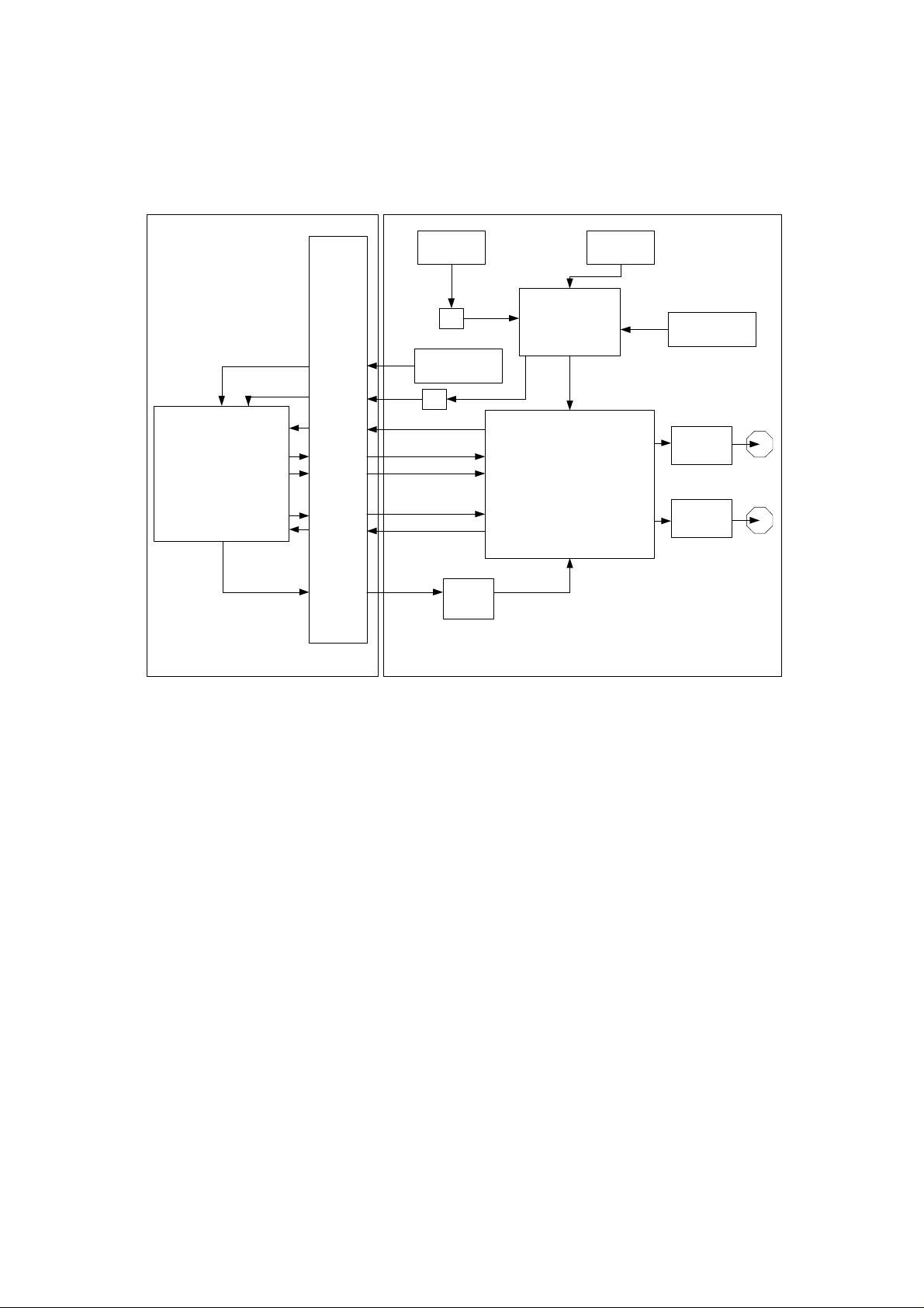
Figure 1. Functional Block diagram of SMT381........................................................12
Figure 2. Internal Data path of the SMT338-VP........................................................15
Figure 3. Clock tree of the SMT381..........................................................................17
Figure 4. Trigger structure of the SMT381 and SMT338-VP.....................................19
Figure 5. Power Generation and distribution............................................................20
Figure 6. Microcontroller State Machine...................................................................21
Figure 7. Option 1 for the SMT381 analog output stage...........................................23
Figure 8. Option 2 for the SMT381 analog output stage...........................................23
Figure 9. Combined analog output circuit.................................................................24
Figure 10. Daughter card connector interface..........................................................27
Figure 11. Daughter Card Interface: Data Signals Connector and Pinout (Bank A).30
Figure 12. Daughter Card Interface: Data Signals Connector and Pinout (Bank B).31
Figure 13. Daughter Card Interface: Data Signals Connector and Pinout (Bank C).32
Figure 14. Rocket Serial Link Interface. ...................................................................33
Figure 15. Rocket Serial Link Interface Connector and Pinout (RSL A)....................34
Figure 16. Rocket Serial Link Interface Connector and Pinout (RSL B)....................35
Figure 17. Samtec HFEM Series Data Cable...........................................................35
Figure 18. Possible SHB Configurations. .................................................................36
Figure 19. SHB Connector Configuration 1 Pinout...................................................37
Figure 20. SHB Connector Configuration 2 Pinout...................................................38
Figure 21. SMT381-VP Firmware State Diagram.....................................................39
Figure 22. Setup Packet Structure. ..........................................................................41
Figure 23. Packet Structure – Defined Commands. .................................................42
Figure 24. Control Register Read Sequence............................................................42
Figure 25. Reset Register (Write Only).....................................................................45
Figure 26. Firmware Version Register (Read Only)..................................................45
Figure 27. Temperature Registers (Read Only)........................................................46
Figure 28. Serial Number Registers (Read Only).....................................................46
Figure 29. Serial Number Registers Cont. (Read Only)............................................47
Figure 30. Clock Source Selection Table (Write Only)..............................................47
Figure 31. Clock Source Register (Write Only).........................................................47
Figure 32. Clock Synthesizer Setup Register (Write Only). ......................................47
Figure 33. PLL Setup Registers (Write Only). ..........................................................48
Figure 34. DAC Setup Registers (Write Only). .........................................................48
Figure 35. SMT 381 PCB layout - TOP. ...................................................................50
Figure 36. SMT 381 PCB layout – BOTTOM............................................................50
Figure 37. SMT381 Top Assembly Drawings. ..........................................................51
Figure 38. SMT381 Bottom Assembly Drawings......................................................51
Figure 39. Main Module Top Assembly Drawing......................................................53
Figure 40. Main Module Bottom Assembly Drawing.................................................54
Figure 41. Side view of SMT381-VP (Height)...........................................................54
Figure 42. Side view of SMT381-VP. .......................................................................55
Figure 43. Top view of SMT381-VP. ........................................................................55
Page 8

Figure 44. Connector Location on SMT381,.............................................................56
Figure 45. FPGA/JTAG connector for the SMT381-VP. ...........................................60
Figure 46. SMT381 to SMT338-VP Interconnection.................................................61
Figure 47. Components Used to Connect the SMT381 to the SMT338-VP..............62
Figure 48. Fitting of Nylon Screws and Nuts to the SMT338-VP. .............................63
Figure 49. Securing the SMT338-VP onto a Sundance Carrier................................63
Figure 50. Connecting the SMT381 to the SMT338-VP............................................64
Figure 51. Time View Captures of LVDS Interface Data...........................................65
Figure 52. Measurements of Time View Capture. ....................................................65
Figure 53. Waveform Memory - Time View Capture – 1000MHz sample frequency
(500MHz VCO Clock) – 125MHz analog output................................................66
Figure 54. Measurements of Capture – 1000MHz sample frequency (500MHz VCO
Clock) – 125MHz analog output........................................................................66
Figure 55. Waveform Memory - FFT – 1000MHz sample frequency (500MHz VCO
Clock) – 125MHz analog output – Channel A....................................................67
Figure 56. Waveform Memory - FFT – 1000MHz sample frequency (500MHz VCO
Clock) – 125MHz analog output – Channel B....................................................67
Figure 57. Waveform Memory - FFT – 1400MHz sample frequency (700MHz
Synthesizer Clock) – 175MHz analog output – Channel A................................68
Figure 58. Waveform Memory - FFT – 1400MHz sample frequency (700MHz
Synthesizer Clock) – 175MHz analog output – Channel B................................68
Figure 59. Waveform Memory - FFT – 600MHz sample frequency (300MHz VCO
Clock) – 75MHz analog output – Channel A......................................................69
Figure 60. Waveform Memory - FFT – 600MHz sample frequency (300MHz VCO
Clock) – 75MHz analog output – Channel B......................................................69
Figure 61. Clock Synthesizer Register.....................................................................70
Figure 62. Clock Synthesizer Frequency Calculation. ..............................................71
Figure 63. DAC serial write operation.......................................................................72
Figure 64. DAC serial read operation.......................................................................72
Figure 65. State machine of the DAC for the SMT381..............................................73
Figure 66. Register Setup for PLL............................................................................74
Figure 67. PLL Configuration Sequence...................................................................75
Figure 68. State Machine Driving the PLL Serial Interface. ......................................76
Figure 69. Test point locations on the SMT381........................................................ 77
Figure 70. Test Program Main Menu........................................................................ 78
Figure 71. SMT338-VP Sub-Menu...........................................................................79
Figure 72. SMT381 Sub-Menu.................................................................................80
Figure 73. Waveform Memory Setup Sequence.......................................................81
Page 9

Precautions (Please Read this!).
In order to guarantee that the SMT381-VP functions correctly and
to protect the module from damage, the following precautions
should be taken:
The SMT381-VP is a static sensitive product and should be
handled accordingly. Always place the module in a static protective
bag during storage and transition.
When operated, make sure that the heat generated by the system
is extracted e.g. by the use of a fan extractor or an air blower.
SHB and RSL connectors are similar but their use is really
different. Do NOT connect an SHB and an RSL connectors
together with and SHB cable! This would cause irreversible
damages to the modules.
Naming Conventions.
The SMT381 refers to a dual channel, 14-bit, 840MSPS DAC
daughter card.
The SMT338-VP refers to a single width Virtex-II Pro based FPGA
module with a Sundance LVDS Bus interface (used for connecting
TIM modules to daughter cards)
The SMT381-VP refers to the SMT381 plugged onto the SMT338VP forming a complete module DAC + FPGA Module.
Page 10

1 Introduction
1.1 Overview
The SMT381-VP is a single width expansion module that plugs onto the SMT338-VP.
It is capable of converting two external digital inputs coming form the SMT338-VP at
840 MSPS with a resolution of 14 bits, or from internal memory at 1GSPS. A Fujitsu
dual channel DAC (MB86064) performs the digital to analogue conversion.
The SMT381 (daughter card) is plugged into the SMT338-VP (main module). Digital
data is then supplied from the SMT338-VP via the daughter card connector over the
Sundance LVDS Bus to the SMT381 which converts the digital data stream to an
analogue signal.
The SMT338-VP controls data transfers via ComPorts, Sundance High-speed Bus
(SHB) or the Rocket Serial Link (RSL) (The RSL interface is not yet implemented).
These interfaces are compatible with a wide range of Sundance processor and I/O
modules.
A very important aspect must be kept in mind by the user. The DAC is rated for
1 GSPS but the SMT338-VP’s FPGA can only supply data to the DAC at 840MHz. It
is however possible to load data into the onboard memory on the DAC. This internal
data can be converted at 1GSPS.
1.2 Module Features
The main features of the SMT381 are listed underneath:
• Dual channel DAC
• 1 GSPS conversion frequency from internal memory
• 840MSPS conversion frequency for data coming from the SMT338-VP
• 14 Bit data resolution
• Custom Clock and Trigger inputs via external connectors
• Internal Waveform generator
• Standard Sundance ComPorts and SHB interfaces for easy interconnection to
Sundance products (interfaces for data sample and non-real-time processing)
1.3 Possible Applications
The SMT381-VP can be used for the following applications (this non-exhaustive list
should be taken as an example):
• Broadband cable modem head-end systems
• 3G Radio transceivers
• High-data-rate point-to-point radios
• Medical imaging systems
• Spectrum analyzers
Page 11

1.4 Related Documents
[1] Sundance High-speed Bus (SHB) specifications – Sundance.
ftp://ftp2.sundance.com/Pub/documentation/pdffiles/SHB_Technical_Specification_v1_0.pdf
[2] RocketIO Serial Links (RSL) specifications – Sundance.
ftp://ftp2.sundance.com/Pub/documentation/pdffiles/RSL_Technical_Specification_v1_0.pdf
[3] TIM specifications.
ftp://ftp2.sundance.com/Pub/documentation/pdf-files/tim_spec_v1.01.pdf
[4] Sundance LVDS Bus (SLB) specifications – Sundance.
http://www.sundance.com/docs/SLB%20-%20Technical%20Specifications.pdf
[5] Virtex-II Pro FPGA datasheet - Xilinx.
http://direct.xilinx.com/bvdocs/publications/ds083.pdf
[6] Fujitsu MB86064 DAC datasheet.
http://www.fme.fujitsu.com
[7] ComPort specification – Texas Instruments.
http://focus.ti.com/lit/ug/spru63c.pdf
Page 12
2 Functional Description
2.1 Module Overview
600MHz 1200MHz
VCO
div
2
SMT338
FPGA
Ext
Trigger
(1d)
Daughter
Card
Connector
The numbers in brackes denote the
Notes:
amount of FPGA IO pins requires.
'd' is used for differential pairs. 1d
Will thus requre 2 IOs
Data Sync Clock (1d)
Data Channel A (14d)
Data Channel B (14d)
Loop Clock (1d)
Loop Clock (1d)
SMT381SMT338-VP
Ext
Trigger
Ch A and Ch B
div
Input Clock (1d)
8
1V8
Convertor
circuit
Figure 1. Functional Block diagram of SMT381.
Clock Generation
Distribution
Digital to Analog
(MB86064)
Control (4)
LVPECL
and
Input Clock
Convertor
25MHz 400MHz
Clock Synth
(1d)
External Clock
Signal
Conditioning
Signal
Conditioning
Output
CHA
Output
CHB
Ch
A
Ch
B
The SMT338-VP sends the digital data to the module via the daughter card
connector. Data is clocked out of the FPGA on both edges of the DAC clock (DDR).
The user can provide this clock by means of the VCO, Clock synthesizer or custom
external clock. The external clock can be provided as an LVPECL clock or as an RF
clock (two separate inputs).
All digital functions on the module are controlled by the SMT338-VP. There are two
14-bit LVDS ports on the DAC which converts the data on a DDR clock. The sampled
data can either be supplied to the DAC cores externally via the LVDS data bus or
internally from the Waveform Memory Module. The data may be routed to the DAC
cores through a number of paths. The most direct path routes data straight from the
LVDS input buffers to the DAC core input latches.
There are two DAC cores present in the MB86064. Thus two channels are available
for outputs. The outputs of the DAC are differential currents, which are converted to a
voltage by the analogue output stage. Details on the set up will be discussed later.
The design of the SMT381 is split over two PCBs. The main PCB (main module –
SMT338-VP) contains the FPGA and the digital connector interfaces (TIM, SHB and
Page 13

RSL). The main memory as well as the MSP430 microprocessor is also located on
this PCB. The second PCB (daughter card – SMT381) contains all the analog
circuitry. The clock generation, trigger control, analog signal conditioning and DAC is
located on this PCB. The SMT381-VP refers to the combination of the SMT338-VP
and the SMT381.
The depth of the SMT381-VP is 21 mm. If the SMT381-VP is mated with a PCI
carrier two PCI slots will be required for the Module + Carrier combination. If the
SMT381-VP is mated with a cPCI carrier the Module + Carrier will require two cPCI
slots.
The FPGA gets control words over a ComPort interface following the Texas
Instruments C4x ComPort standard. The FPGA receives data through the onboard
memory or SHB interface. It is then sent to the DAC cores over two 14-bit LVDS
busses according to the SLB standard. The DACs convert the data and sends the
data to the output connectors.
Two full (60-pin) SHB connectors are accessible from the FPGA. Their main function
is to receive digital samples from other modules. Please refer to the SHB
specification for more details about the way connectors can be configured.
A global reset signal is mapped to the FPGA from the bottom TIM connector via the
MSP430 microcontroller.
2.2 Communication Ports (ComPorts)
The SMT381-VP provides two ComPorts – ComPort 0 and ComPort 3. Both of these
ComPorts are connected to the FPGA on the SMT338-VP. ComPort 3 is also
connected to the MSP430 microprocessor. The microprocessor is the master of this
ComPort after reset and configures the FPGA with configuration data received over
this link. After configuration the microprocessor releases the ComPort to the FPGA.
These ComPorts are driven at 3.3V levels.
2.3 Sundance High-Speed Bus (SHB)
Two SHB connectors are used to transmit data to the SMT381-VP from the external
world. Both SHB busses are identical and 60-bits wide. See the SHB specification
for more information.
Page 14
2.4 Main Analogue characteristics
The main analogue characteristics are listed in the following table:
Analogue outputs
Output current range 20mA
Data Format Analogue current
External sampling clock inputs (The clock frequency is divided by 2 on the SMT381 for a DDR clock for the DAC)
LVPECL Clock
Signal format LVPECL
Frequency range 25MHz to 1000 MHz
RF Clock
Signal format Sinus wave
Frequency range 25MHz to 1000 MHz
Amplitude 0dBm Typ
External trigger inputs
Signal format LVPECL
Frequency range DC to 100 MHz
ADC Performance @ Single tone at -1dBFS, 800MSa/s, DC to 400MHz (From DAC datasheet)
Spurious Free Dynamic Range (SFDR) @ 20MHz
Spurious Free Dynamic Range (SFDR) @ 300MHz
Cross-talk 4 tone test, each tone at -15dBFS, centred at 276MHz
75dBc
58dBc
67dBc
Table 1. Main analogue characteristics of the SMT381.
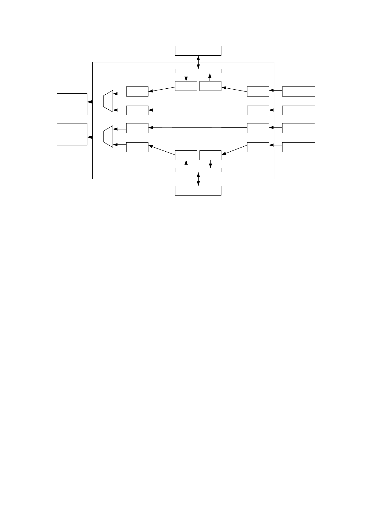
2.5 Data stream description
The data paths for both channels on the module are the same. The DAC is driven by
a single clock either generated on the module or provided by the user through an
MMBX connector. As only a single clock is present on the module the two data-paths
will always be in exact synchronization. As the data path on this module finds its
origin in the SMT338-VP’s FPGA the internal data path of the FPGA must also be
explained. Figure 2 shows the SMT338-VP’s FPGA data path.
Page 15
DDR SDRAM
Memory Interface
DAC
Channel A
DAC
Channel B
Mux
Mux
Pre-process
Data
Pre-process
Data
Pre-process
Data
Pre-process
Data
Retrieve from
Memory
Retrieve from
Memory
Memory Interface
DDR SDRAM
Store in
Memory
Store in
Memory
SHB
Interface
SI
SI
SHB
Interface
SHB for Channel A
RSL for Channel A
RSL for Channel B
SHB for Channel B
Figure 2. Internal Data path of the SMT338-VP.
The digital data stream is received from two interfaces. The first data stream is a
direct RSL interface for real-time type applications (RSL is not yet implemented).
While the second stream comes from the DDR SDRAM memory for non-real-time
type module transmits (the memory is initialized over the SHB interface).
Each data stream is then conditioned and sent to the SMT381 via the daughter card
connector. A multiplexer selects between the two data streams.
2.5.1 Description of internal FPGA blocks
Pre-processing Data
The user can implement his own type of processing on the data stream if required.
SI
The Serial Interface block takes the high-speed serial input data stream and converts
it into a parallel data stream (Not yet implemented).
Mux
The multiplexer connected to the RSL and SHB/memory interfaces selects between
these two data streams to send to the SMT381.
Store in Memory
The store in memory block takes the incoming data stream from the SHB and stores
the data into DDR SDRAM. This block will only transfer data from the memory to the
SMT381 when a valid trigger command is received. The amount of data that must be
stored is configurable.
Page 16

Memory Interface
The memory interface block is the DDR SDRAM controller. This block is responsible
to all write and read transactions to and from the DDR SDRAM.
Retrieve from Memory
The retrieve from memory block retrieves stored data in the DDR SDRAM when it
receives a valid read command. The read command specifies the location and
amount of data that needs to be retrieved.
SHB Interface
The data received from the SHB interface is stored in memory. The SHB interface
controls the SHB bus between the SMT338-VP and any module connected to the
SHB sending the data.
In addition to the above interface blocks the FPGA also implements the following
functions (not indicated on the diagram):
Trigger Interface
Handles all triggers. Triggers may be received from the external hardware trigger
connectors (two separate triggers – one for each channel), or by receiving a trigger
command over the ComPort (also separate commands for each channel). When a
trigger is received data is sent to the SMT381 from the memory on the SMT338-VP.
DAC Control Interface
Control interface for writing setup information to the DAC on the SMT381 to configure
it for any selected mode of operation. Data is received over the ComPort interface
and written out to the DAC over a serial interface.
Clock Synthesizer Interface
Control interface for writing setup information to the clock synthesizer on the SMT381
to configure its clock output frequency. Data is received over the ComPort interface
and written out to the clock synthesizer over a serial interface.
PLL Interface
Control interface for writing setup information to the PLL on the SMT381 to configure
the VCO output voltage. Data is received over the ComPort interface and written out
to the PLL over a serial interface. The PLL drives one VCO circuit. This VCO + PLL
circuit generates the main system clock and is configurable between 600 and 1200
MHz. The side is called the RF side. This clock is then divided by two which enables
the DAC to have a very stable PLL + VCO clock ranging from 300 to 600MHz.
DAC Interface
The DAC interface sends a high speed data stream from the FPGA to the DAC
present on the SMT381. There are two channels available on the DAC and data is
latched into the DAC on the rising and falling edge (DDR) of the DAC’s input clock
which is clocked into the FPGA to make data synchronization easier. The inputs are
14bit data streams which is clocked out of the FPGA at a maximum frequency of
420MHz (on both edges, thus 840MSPS).
Page 17

Clock Tree Setup Interface
There are various clock routing configurations available for the SMT381. This
interface configures the clock tree.
2.6 Clock Structure
There are two integrated clock generators on the module. The user can either use
these clocks or provide the module with an external clock (input via MMBX
connectors). The following figure shows the SMT381 clock tree.
External Clocks
Ext RF
Clock
Input
(MMBX)
ECL
Comp-
arator
2:1 Mux
Clock Div 2
External Trigger
External Trigger Input
(MMBX)
Ext
LVPECL
Clock
Input
(MMBX)
ECL
Reciever/
Driver
Clock
Div 8
Clk Synth (25MHz -
400MHz)
Clk Synth
LVPECL
Buffer
3:1 Mux with Dual Output
Fanout
Buffer
DAC
VCO (600MHz -
1200MHz)
PLL
Voltage Controlled
Oscillator
Comparator
div 2
TTL to LVPECL
Loop
Clock
DAC clock
output
(MMBX)
LVPECL
Buffer
PLL
SMT338
Data
Clock
Clock
Control
Figure 3. Clock tree of the SMT381.
The main clock tree of the SMT381 consists of two clock sources to achieve the
DAC’s full range of input frequencies (DC – 500MHz). The first clock source is a
MICREL clock synthesizer which has a range from 50MHz to 950MHz. This source’s
disadvantage however is that it has a jittery output and thus the clock is not that
stable. Its advantage however is that it can attain a wide range of frequencies,
especially the lower frequencies. The output clock is LVPECL.
Page 18

The second clock source is a voltage controlled oscillator with a phase lock loop.
This combination has a very stable output. However a limited frequency range can be
attained by this combination (300MHz – 600MHz). This is achieved by taking a
600MHz -1200MHz VCO and dividing the output by 2. The output clock must also be
scaled to LVPECL.
Alternatively the user can provide the module with an external LVPECL clock or an
external RF clock. The user can select between any of these input clocks.
The selected clock then drives the DAC and is also distributed to the main module
(SMT338-VP) for data synchronization purposes. On the FPGA of the SMT338-VP a
PLL synchronizes the clock with the data being sent by using the supplied clock and
looping that same clock to the DAC and back. This technique synchronizes the clock
to the data is being sent out on (SMT338-VP side) even further with the clock used in
the DAC. Synchronization issues become a bigger factor as the clock frequencies get
bigger.
All the clock control is done on the SMT338-VP side in firmware on the FPGA. The
multiplexer selects the clock and this clock is then used inside the DAC and SMT338VP for data transmitting purposes. The set up of the clock packages is also done in
firmware.
Finally an external trigger is supplied to the SMT338-VP and the multiplexed clock
divided by 8. The trigger can be used for memory storing and retrieving functions etc.
while the clock divided by 8 is mainly for debugging purposes.
2.7 Trigger Structure
There are two main data-paths (per channel) for data received either from RSL
interface (not yet implemented) or SHB/memory interface. The first data path is
directly connected to the DAC interface and sends the data as is. The second data
path is either a direct link to the DAC interface or to memory. The trigger settings
differ depending on the path used.
There are two main sources for the trigger. The first is an LVPECL trigger received
over the MMBX connector (triggered on rising edge). The second is a trigger
command. The trigger command can be received either over the RSL interface or via
the ComPorts.
The following trigger settings are possible for the RSL interface (RSL not yet
implemented):
• Start transmitting data when a trigger is received. Stop transmitting when the
next trigger is received.
• Transmit a pre-determined amount of samples when a trigger is received.
• Ignore all triggers and transmit data continuously (cycle through memory).
The following trigger settings are possible for the DDR SDRAM data-path:
Page 19

• Transmit a pre-determined amount of samples when a trigger is received, and
carry on cycling through them.
The following diagram is a graphical representation of the trigger structure and
sources on the SMT381 and SMT338-VP:
FPGAExternal Trigger
RSL CDR Interface
RSL Rx Cmd State
Trigger Generation
External Trigger Input
(MMBX)
LVPECL
Buffer
SMT338-VP
ComPort Interface
ComPort Rx Cmd
State Machine
Trigger Generation
SMT381
Trigger Setup
Register
Figure 4. Trigger structure of the SMT381 and SMT338-VP.
Machine
Trigger
Distribution
2.8 Power Supply and Reset Structure
The SMT381 uses the following voltages: 12V, -12V, 5V, -5.2V, 3.3V and 1.8V. Only
two voltages must be generated on the SMT381 as the rest are supplied by the
carrier. The voltages that must be generated are -5.2V and 1.8V. -5.2V is used for
the comparator and op amp in the clock circuitry while 1.8V is used for the serial
control interface on the DAC.
All the other voltages are supplied by the carrier and thus present on the SMT338-
VP. The required voltages are then supplied to the SMT381 by a daughter card
power connector present on the SMT338-VP and SMT381. The SMT381 plugs into
this power connector and thus has power for all its modules.
Pin X_RESET is the only reset option on the SMT381. This pin resides on the DAC.
On the falling edge of X_RESET the DAC is reset and all registers are set to their
default values. After a reset most parts of the device are powered down.
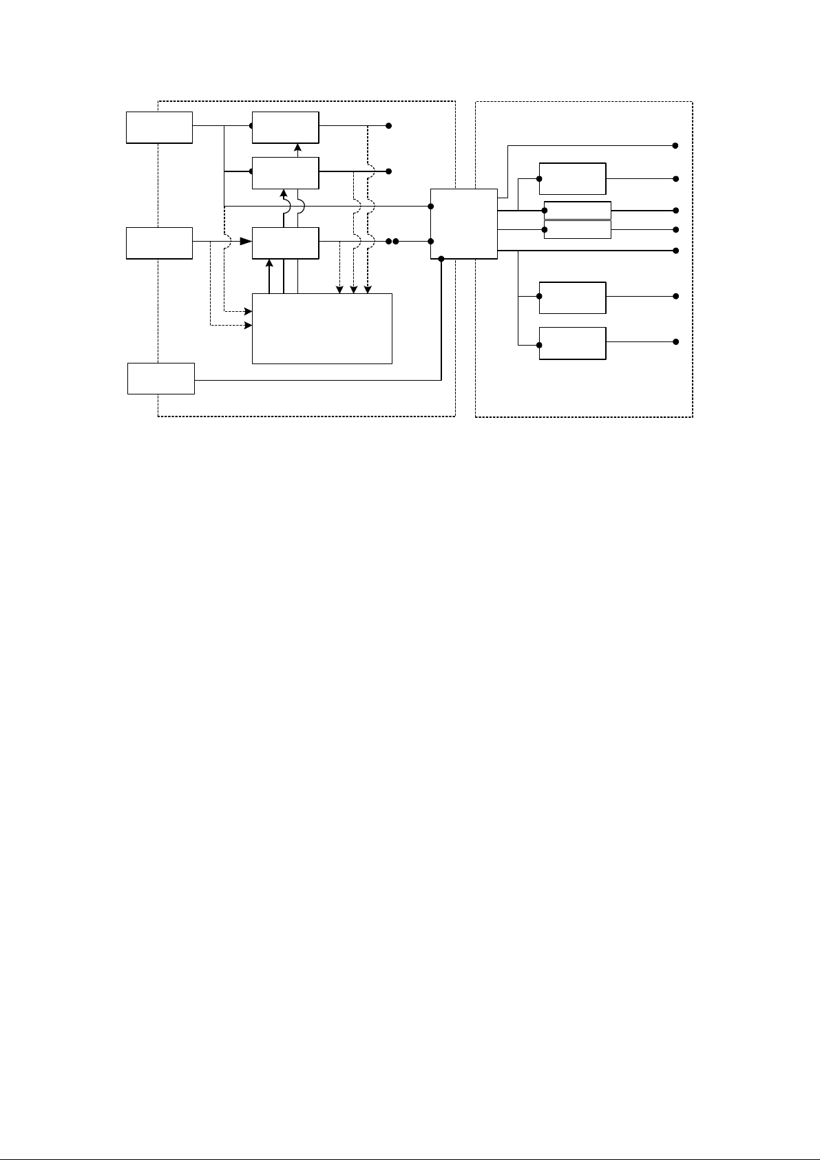
The following figure shows the power structure of the SMT338-VP and SMT381:
Page 20
TIM Connector
D+5V0_IN
Vccaux
DC / DC
Converter
D+2V5
Daughter Card
D+5V0
TIM
Mounting Hole
D+3V3_IN
TIM Connector
D+12V0 and
D-12V0
Voltage
Measure
Vccint
DC / DC
Converter
Analog Power
Switch
Microprocessor
On / Off
Control
MSP430
D+1V5
D+3V3
Voltage
Measure
Main Module to
Daughter Card
Power
Connector
Low Dropout
Regulator
Analog Filter
Analog Filter
Analog Filter
Low Dropout
Regulator
D-5V2
D-12V0
D+12V0
D+3V3
A+3V3
D+1V8
Main Module
Figure 5. Power Generation and distribution.
2.9 MSP430 Functionality
The MSP430 implements analog control functionality that is difficult to implement in
the FPGA. The microprocessor
• Controls the power start-up sequence
• Controls the reset structure on the module
Page 21
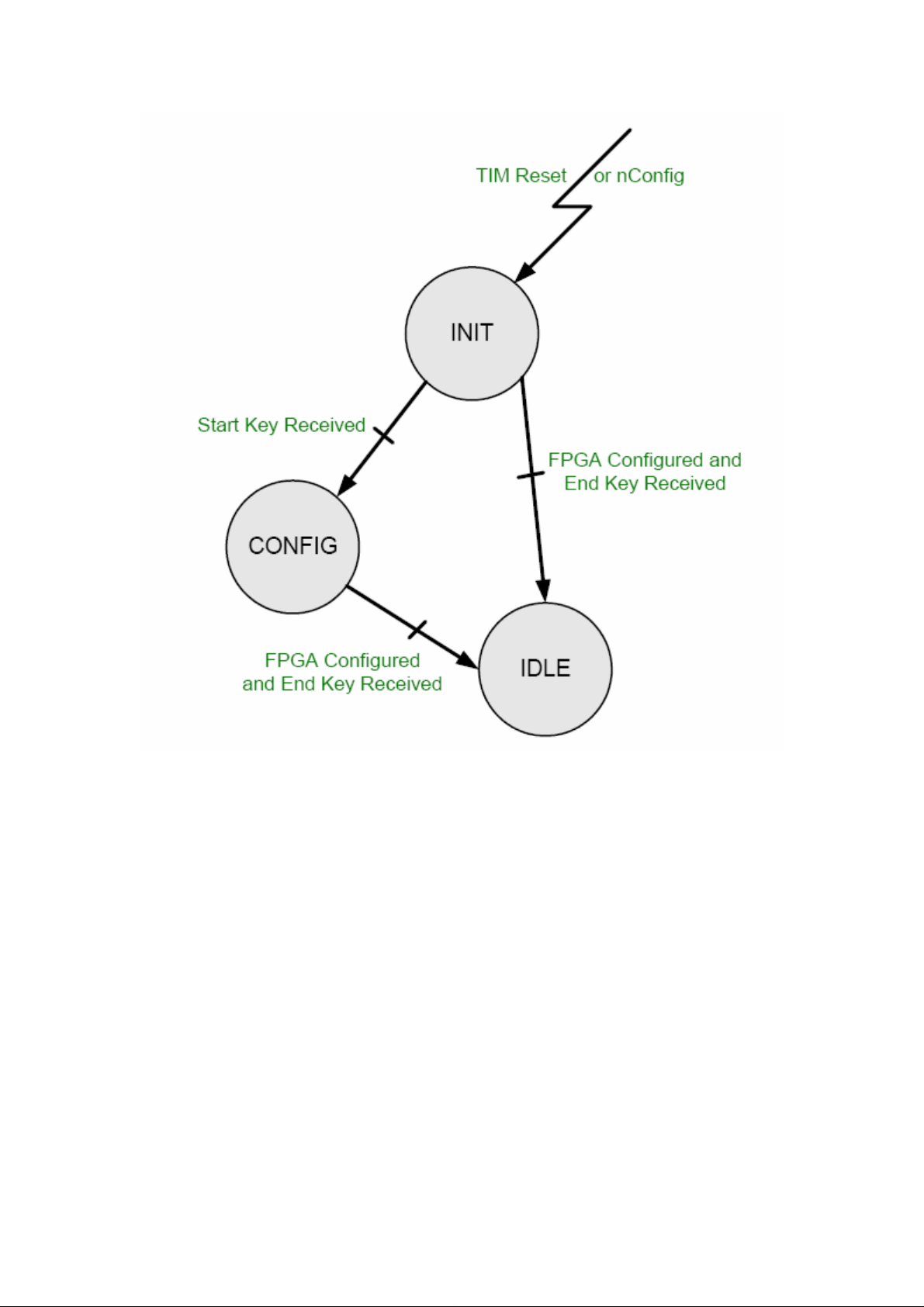
Figure 6. Microcontroller State Machine.
At power-up or on a TIM Reset or on a nConfig line going low, the state machine
goes into an INIT State. TIM Reset and nConfig lines are available on the carrier
module – see TIM Specifications for location on TIM connectors).
From there, it has two choices depending on the state of the FPGA (configured i.e.
DONE pin high or un-programmed i.e. DONE Pin Low). To configure the FPGA,
simply send a Start Key followed by the bitstream and then and End Key. To re-start
the FPGA with the current bitstream loaded, simply send a End Key.
Start Key = 0xBCBCBCBC and End Key = 0xBCBCBC00.
A TIM Reset can be issued to reconfigure the FPGA at anytime, but may reset other
modules as well. In the case of reconfiguring a particular module, the nConfig line is
used.
Page 22

MSP430 is connected to ComPort 3 of the TIM. With the standard firmware
implementation ComPort 3 is used to communicate with the FPGA. ComPort 0 is
open for custom applications as it is not used by the SMT381-VP.
2.10 FPGA Configuration
In a typical Sundance system a carrier and host module (most likely a DSP module)
is needed to configure the SMT381-VP.
After a hardware reset the FPGA of the SMT381-VP is un-configured and the
microprocessor (MSP430) waits for a data stream. At this point the microprocessor is
in control of ComPort 3. The host can then send a data stream over ComPort 3
starting with a STARTKEY, then the data, and ending with an ENDKEY. This will
configure the FPGA via the microprocessor, and after configuration the
microprocessor will release ComPort3 so that the host can talk straight to the FPGA.
If at any time the host want to reset the FPGA the host must send a reset command
to it the SMT381-VP over the ComPort – Any hardware resets coming over the TIM
site will be caught by the microprocessor but will not be passed on to the FPGA.
If the FPGA is configured, but the host restarts its application, it must send an
ENDKEY only. This will ‘wake up’ the FPGA and the uP will release ComPort 3 so
that the host can use it for FPGA communication.
If the host want to reconfigure the FPGA it must toggle the nConfig line on the TIM
site. This will give control of the ComPort back to the microprocessor, but it will not
un-configure the FPGA. If the host then start sending a new bit-stream starting with a
STARTKEY, the FPGA will be un-configured and the new bit-stream will load. If after
toggling the nConfig line, if the host does not want to re-configure the FPGA, it must
send an ENDKEY like described above.
The above structure makes it possible to:
• Reset only the FPGA in the system and
• Make sure that the FPGA is not un-configured every time the host application
is re-run as it takes time for the FPGA to re-configure (approximately 35
seconds).
2.11 Analogue output section
Two options are hardwired into the design. The options are shown below with a
figure of each.
Option 1
Single ended AC coupled output with Macom TP-101 transformer.
Page 23
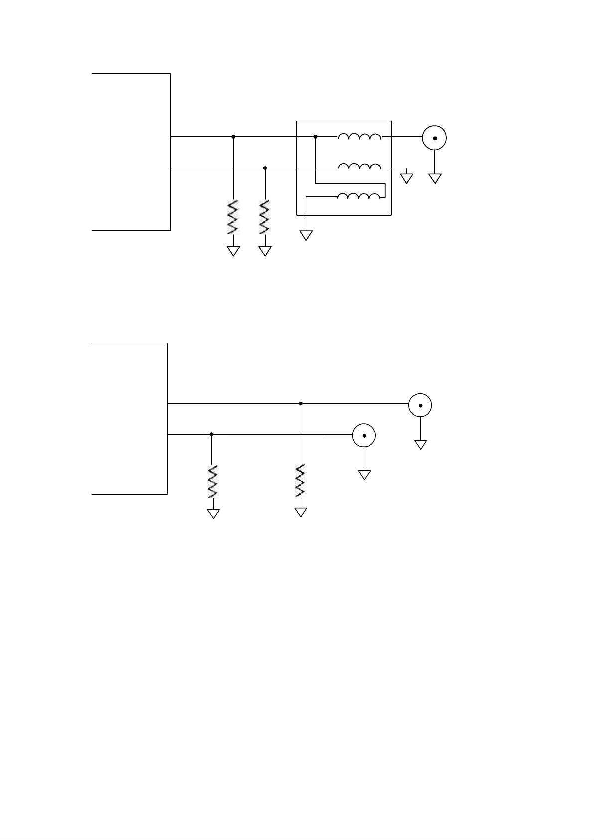
TP101
+
Output
Connector
-
R1 R1
Figure 7. Option 1 for the SMT381 analog output stage.
Option 2
Differential DC coupled output with + and – channels going to separate connectors
+
Output
Connector
-
R2
Figure 8. Option 2 for the SMT381 analog output stage.
R2
Output
Connector
Page 24
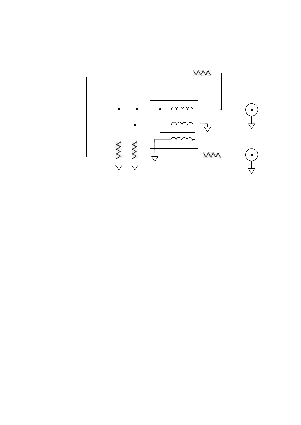
Combined circuit
The two combined:
+
-
0 ohm
TP101
R3 R3
0 ohm
Figure 9. Combined analog output circuit.
Depending on whether an AC or DC coupled version is ordered the board will be
assembled accordingly to either give the AC or DC coupled circuit shown above.
For more information consult the Fujitsu (MB86064) DAC datasheet [6].
2.12 DAC Settings
All DAC settings are controlled and implemented by the 4 wire serial control
interface. The serial interface uses pins SERIAL_IN, SERIAL_OUT, SERIAL_CLK
and SERIAL_EN. Programmed settings are stored in a number of registers which are
individually accessible using either a 7-bit (WMM Registers) or 10-bit (DAC Core
Registers) address/control word. Data may be written to or read from each of these
registers.
For more information consult the Fujitsu (MB86064) DAC datasheet [6].
3 Description of interfaces
3.1 DAC Control Interface
A four wire uni-directional control interface is implemented between the FPGA and
the DAC. This interface is used for clocking configuration information into the DAC.
Page 25

Note 1: The serial interface on the DAC side uses 1.8V signalling levels. These
control lines are however connected unto a 3.3V bank on the FPGA with additional
pull-up resistors on the SMT381 to 1.8V. For this reason the FPGA firmware may
never drive ‘1’ out on these pins as it will drive the DAC at 3.3V and thus damage it.
The firmware may only drive ‘0’ for ‘0’ and ‘Z’ for ‘1’. Because of the pull-up resistor
the ‘Z’ will be pulled up to 1.8V. This approach works well and any used wishing to
develop his own firmware is advised to take a look at the SMT381 example firmware
before developing his own.
3.2 DAC Data Interface
The output of each channel from the SMT338-VP to the DAC is a 14 bit LVDS data
bus clocked on the synchronized DAC clock.
Note 1: The data bus between the FPGA and the DAC is wired in a strange way to
assist routing. If a user wants to develop his own VHDL design and not use the
example design he is advised to take a look at the wiring of the example design to
assist him with his own design.
Note 2: On Rev 01 of the SMT381 the positive and negative data pairs of the LVDS
bus between the FPGA and the DAC is swapped for one of the two channels. This
results in a data flip. This issue is corrected in firmware by inverting the data before
writing it out over the interface. Once again any user wanting to do his own design is
advised to take a look at the example firmware design.
3.3 Memory Interface
Two groups of two 16 bit Micron DDR SDRAMs form the volatile sample storage
space of the module. Each DDR SDRAM is 256 MBits in size. This provides the
module with a total of 64Mbytes (or 32 Mega samples) of storage space per channel.
Each channel contains a 32 bit DDR SDRAM controller. This interface is capable of
data transfer at 1 GBytes / s. It is thus fast enough to write the outgoing DAC data
stream.
3.4 MSP430 Interface
After configuration the microprocessor communicates with the FPGA using the IO
pins of the FPGA Slave Select Configuration interface. The MSP is the master of the
interface and will continually write the serial number and the measured on-board
voltages to the FPGA. A system host can then read this data from the FPGA over the
ComPort interface.
3.5 Serial Number
A Maxim 1-Wire silicon serial number device is located on the SMT381 and the
SMT338-VP. This is used to assign a unique serial number to each module.
3.6 PLL Interface
A three wire uni-directional control interface is implemented between the FPGA and
the PLL on the daughter card. This PLL sets and controls the voltage for the VCO
that generates the main clock.
Page 26

3.7 Clock Synthesizer Interface
A three wire uni-directional control interface is implemented between the FPGA and
the Micrel clock synthesizer on the daughter card. The clock synthesizer can
generate a variable 50 – 950 MHz clock. The jitter on this clock is higher than on the
main PLL+VCO clock, but it is convenient for testing.
3.8 TIM Interface
The SMT381-VP implements ComPorts 0 and 3. There are no DIP switches on the
module and all configuration data is received and transmitted over these two ports.
The ComPorts are not used for DAC data transfer. ComPort 3 is implemented as a
bi-directional transceiver interface for FPGA configuration and control operations.
ComPort 0 is available but not used in the default firmware provided with the board.
The Global Bus Interface is not implemented on the SMT381. Refer to [3] for a more
detailed description of the TIM interface.
3.9 External Trigger
The external trigger input is received by a LVPECL input buffer on the SMT381. The
buffered signal is passed down as a differential LVPECL signal to the FPGA on the
SMT338-VP. For compatibility reasons with other daughter card modules there are
no ECL termination resistors mounted on the SMT338-VP. For this reason the pulse
width of the input trigger must be at least 1uS before the FPGA will register it.
As this might be a problem for some applications this issue has been resolved on the
newer SMT338-VP modules and appropriate termination resistors are provided to
improve the response time of the FPGA to an external trigger.
For most systems it is likely that there will be a system host (DSP Module). For this
reason it is also possible to send a software trigger to the SMT381-VP over ComPort
3. There will however be a latency from the time that the command is sent to the time
that data is read from the memory.
3.10 Daughter card Interface
The daughter-card interface is made up of two connectors. The one is a 0.5mm pitch
differential Samtec connector. This connector is for transferring digital LVDS data to
the DAC from the main module. The second one is a 1mm pitch Samtec header type
connector. This connector is for providing power to the daughter-card.
The figure underneath illustrates this configuration. The bottom view of the daughter
card is shown on the right. This view must the mirrored to understand how it
connects to the main module.
Page 27

Top Primary TIM Connector
Bank A Bank B Bank C
Power Connector
DDR266 SDRAM
Samsung
DDR266 SDRAM
Samsung
Power
Data Connectors
Power Connector
RSL
SHB
B
Xilinx
Virtex-II Pro
XC2VP30-6
FF896 Package
B
FPGA
Config
Global Bus Connector
SMT338-VP SMT381
RSL
SHB
A
A
Figure 10. Daughter card connector interface
The female differential connector is located on the main module. The Samtec Part
Number for this connector is QTH-060-01-F-D-DP-A.
The female power connector is located on the main module. The Samtec Part
Number for this connector is BKS-107-01-F-V-A
The male differential connector is located on the daughter card. The Samtec Part
Number for this connector is QSH-060-01-F-D-DP-A
The male power connector is located on the daughter card. The Samtec Part Number
for this connector is BKT-107-03-F-V-A
The mated height between the main module and the daughter card is 5 mm.
Each pin on the power connector can carry 1.5 A. Digital 5V (D+5V0), digital 3V3
(D+3V3), digital 12V0 (D+12V0), digital -12V0 (D-12V0) and digital ground (DGND) is
provided over this connector. D+3V3 and D+5V0 are assigned four pins each while
D+12V0 and D-12V0 are assigned two each. The daughter card can thus draw a
total of 6A for the D+3V3 and D+5V0 supplies while D+12V0 and D-12V0 can only
supply 3A. The integral ground plane on the differential connector provides additional
grounding. The following table shows the pin assignment on the power connector:
Page 28

Pin Number Pin Name Description of Signal
1 D+3V3 Digital 3.3 Volts
2 DGND Digital Ground
3 D+3V3 Digital 3.3 Volts
4 DGND Digital Ground
5 D+3V3 Digital 3.3 Volts
6 DGND Digital Ground
7 D+3V3 Digital 3.3 Volts
8 DGND Digital Ground
9 D+5V0 Digital 5.0 Volts
10 DGND Digital Ground
11 D+5V0 Digital 5.0 Volts
12 DGND Digital Ground
13 D+5V0 Digital 5.0 Volts
14 DGND Digital Ground
15 D+5V0 Digital 5.0 Volts
16 DGND Digital Ground
17 D+12V0 Digital 12.0 Volts
18 DGND Digital Ground
19 D+12V0 Digital 12.0 Volts
20 DGND Digital Ground
21 D-12V0 Digital -12.0 Volts
22 DGND Digital Ground
23 D-12V0 Digital -12.0 Volts
24 DGND Digital Ground
25 DGND Digital Ground
26 NC
27 NC
28 NC
29 NC
30 NC
Page 29

31 TDI Loop with TDO
32 TDO Loop with TDI
33 DGND Digital Ground
Table 2. Daughter Card Interface Power Connector and Pinout.
The following few pages describes the signals on the data connector between the
main module and the daughter card. Bank A on the connector is used for the DAC
Channel A data bus. Bank C is used for the DAC channel B data bus. Bank B is used
for system clock and trigger signals, DAC control signals and general system control
signals. The general system control signals include: clock control interface (for the
clock modules present on the SMT381), daughter card sense signal, daughter card
ID signals, low drop out regulator control signals and daughter card DAC reset signal.
All reserved signals are connected to the FPGA on the main module for future
expansion.
Page 30

Bank A Bank B Bank C
1 3 5 7 41 43 81 83
2 4 6 8
Bank A
Pin No Pin Name Signal Description Pin No Pin Name Signal Description
Dir Main Module to Daughter Card Dir Main Module to Daughter Card
1 DOAI0p Data In 0 Channel A, pos. 2 DOBI0p Data In 1 Channel A, pos.
3 DOAI0n Data In 0 Channel A, neg. 4 DOBI0n Data In 1 Channel A, neg.
Dir Main Module to Daughter Card Dir Main Module to Daughter Card
5 DOAI1p Data In 2 Channel A, pos. 6 DOBI1p Data In 3 Channel A, pos.
7 DOAI1n Data In 2 Channel A, neg. 8 DOBI1n Data In 3 Channel A, neg.
Dir Main Module to Daughter Card Dir Main Module to Daughter Card
9 DOAI2p Data In 4 Channel A, pos. 10 DOBI2p Data In 5 Channel A, pos.
11 DOAI2n Data In 4 Channel A, neg. 12 DOBI2n Data In 5 Channel A, neg.
Dir Main Module to Daughter Card Dir Main Module to Daughter Card
13 DOAI3p Data In 6 Channel A, pos. 14 DOBI3p Data In 7 Channel A, pos.
15 DOAI3n Data In 6 Channel A, neg. 16 DOBI3n Data In 7 Channel A, neg.
Dir Main Module to Daughter Card Dir Main Module to Daughter Card
17 DOAI4p Data In 8 Channel A, pos. 18 DOBI4p Data In 9 Channel A, pos.
19 DOAI4n Data In 8 Channel A, neg. 20 DOBI4n Data In 9 Channel A, neg.
Dir Main Module to Daughter Card Dir Main Module to Daughter Card
21 DOAI5p Data In 10 Channel A, pos. 22 DOBI5p Data In 11 Channel A, pos.
23 DOAI5n Data In 10 Channel A, neg. 24 DOBI5n Data In 11 Channel A, neg.
Dir Main Module to Daughter Card Dir Main Module to Daughter Card
25 DOAI6p Data In 12 Channel A, pos. 26 DOBI6p Data In 13 Channel A, pos.
27 DOAI6n Data In 12 Channel A, neg. 28 DOBI6n Data In 13 Channel A, neg.
Dir Reserved Dir Reserved
29 Reserved Reserved 30 Reserved Reserved
31 Reserved Reserved 32 Reserved Reserved
Dir Daughter Card to Main Module Dir Main Module to Daughter Card
33 ClkOIp Output Ready, I channel,
pos
35 ClkOIn Output Ready, I channel,
neg
Dir Daughter Card to Main Module Dir Daughter Card to Main Module
37 SysClockp System clock, pos. 38 ExtTriggerIp External Trigger A, pos.
39 SysClockn System clock, neg. 40 ExtTriggerIn External Trigger A, neg.
34 DOIRIp Loop back clock to DAC, pos.
36 DOIRIn Loop back clock to DAC, neg.
Figure 11. Daughter Card Interface: Data Signals Connector and Pinout (Bank A).
Page 31

Bank A Bank B Bank C
1 3 5 7 41 43 81 83
2 4 6 8
Bank B
Pin No Pin Name Signal Description Pin No Pin Name Signal Description
Type MSP system signals Type MSP system signals
Dir Bi-Directional Dir Bi-Directional
41 SMBClk TmpCntrl0 42 SMBData TmpCntrl1
43 SMBnAlert TmpCntrl2 44 SerialNo Serial Number
45 Reserved Reserved 46 Reserved Reserved
47 Reserved Reserved 48 Reserved Reserved
49 D3V3Enable D3V3Enable 50 D1V8Enable D1V8Enable
Type FPGA system signals Type FPGA system signals
Dir Bi-Directional Dir Bi-Directional
51 DACCntrl0 DAC Control 0 52 DACCntrl0 DAC Control 1
53 DACCntrl0 DAC Control 2 54 DACCntrl0 DAC Control 3
55 DACCntrl0 DAC Control 4 56 AdjClkSClk AdjClockCntrl0
57 AdjClkSData AdjClockCntrl1 58 AdjClkSLoad AdjClockCntrl2
59 AdjClkTest AdjClockCntrl3 60 PllClk PllCntrl0
61 PllData PllCntrl1 62 PllLe PllCntrl2
63 PllFoLd PllCntrl3 64 AdcAClkSel AdcAClkSel
65 AdcBClkSel AdcBClkSel 66 IntClkDivEn IntClkDivEnable
67 IntClkDivnReset IntClkDivnReset 68 IntExtClkSel IntExtClkSel
69 IntExtClkSelnReset IntExtClkSelnReset
Type FPGA JTAG Type FPGA JTAG
Dir Bi-Directional Dir Bi-Directional
71 FpgaTck FpgaTck 72 FpgaTms FpgaTms
73 FpgaTdi FpgaTdi 74 FpgaTdo FpgaTdo
Type MSP JTAG Type MSP JTAG
Dir Bi-Directional Dir Bi-Directional
75 MspVref MspVref 76 MspTck MspTck
77 MspTms MspTms 78 MspTdi MspTdi
79 MspTdo MspTdo 80 MspnTrst MspnTrst
70 FpgaVref FpgaVref
Figure 12. Daughter Card Interface: Data Signals Connector and Pinout (Bank B).
Page 32

Bank A Bank B Bank C
1 3 5 7 41 43 81 83
2 4 6 8
Bank C
Pin No Pin Name Signal Description Pin No Pin Name Signal Description
Dir Daughter Card to Main Module Dir Daughter Card to Main Module
81 DOAQ0p Data In 0 Channel B, pos. 82 DOBQ0p Data In 1 Channel B, pos.
83 DOAQ0n Data In 0 Channel B, neg. 84 DOBQ0n Data In 1 Channel B, neg.
Dir Daughter Card to Main Module Dir Daughter Card to Main Module
85 DOAQ1p Data In 2 Channel B, pos. 86 DOBQ1p Data In 3 Channel B, pos.
87 DOAQ1n Data In 2 Channel B, neg. 88 DOBQ1n Data In 3 Channel B, neg.
Dir Daughter Card to Main Module Dir Daughter Card to Main Module
89 DOAQ2p Data In 4 Channel B, pos. 90 DOBQ2p Data In 5 Channel B, pos.
91 DOAQ2n Data In 4 Channel B, neg. 92 DOBQ2n Data In 5 Channel B, neg.
Dir Daughter Card to Main Module Dir Daughter Card to Main Module
93 DOAQ3p Data In 6 Channel B, pos. 94 DOBQ3p Data In 7 Channel B, pos.
95 DOAQ3n Data In 6 Channel B, neg. 96 DOBQ3n Data In 7 Channel B, neg.
Dir Daughter Card to Main Module Dir Daughter Card to Main Module
97 DOAQ4p Data In 8 Channel B, pos. 98 DOBQ4p Data In 9 Channel B, pos.
99 DOAQ4n Data In 8 Channel B, neg. 100 DOBQ4n Data In 9 Channel B, neg.
Dir Daughter Card to Main Module Dir Daughter Card to Main Module
101 DOAQ5p Data In 10 Channel B, pos. 102 DOBQ5p Data In 11 Channel B, pos.
103 DOAQ5n Data In 10 Channel B, neg. 104 DOBQ5n Data In 11 Channel B, neg.
Dir Daughter Card to Main Module Dir Daughter Card to Main Module
105 DOAQ6p Data In 12 Channel B, pos. 106 DOBQ6p Data In 13 Channel B, pos.
107 DOAQ6n Data In 12 Channel B, neg. 108 DOBQ6n Data In 13 Channel B, neg.
Dir Reserved Dir Reserved
109 Reserved Reserved 110 Reserved Reserved
111 Reserved Reserved 112 Reserved Reserved
Dir Daughter Card to Main Module Dir Daughter Card to Main Module
113 ClkOQp Output Ready, Q channel,
pos
115 ClkOQn Output Ready, Q channel,
neg
Dir Daughter Card to Main Module Dir Daughter Card to Main Module
117 RslClockp Rsl Clock, pos. 118 ExtTriggerQp External Trigger A, pos.
119 RslClockn Rsl Clock, neg. 120 ExtTriggerQn External Trigger A, neg.
114 DOIRQp Loop back clock to FPGA, pos.
116 DOIRQn Loop back clock to FPGA, neg.
Figure 13. Daughter Card Interface: Data Signals Connector and Pinout (Bank C).
Page 33

3.11 RSL Interface (RSL not yet available)
3.11.1 RSL Connector and Pinout Definition
The Rocket Serial Link (RSL) is a serial based communications interconnection
standard that is capable of transfer speeds of up to 2.5GBit/s per link. Up to four links
can be combined to form a Rocket Serial Link Communications Channel (RSLCC)
that is capable of data transfer up to 10GBit/s.
Each RSL is made up of a differential Tx and Rx pair. A single RSL can thus transfer
data at 2.5GBit/s in both directions at the same time. Rocket Serial Link
interconnections are based on the RocketIO standard used on Xilinx Virtex-II Pro
FPGAs. Rocket Serial Links uses Low Voltage Differential Signaling (LVDS).
The SMT381-VP uses a subset of the RSL specification. Four RSLs are combined to
form a 10GBit/s RSLCC. One RSLCC per DAC channel is implemented on the
SMT381-VP. The RSLCC is thus capable to transfer a raw data stream to the DAC in
real time.
The connector used for the RSL interface is a 0.8mm pitch differential Samtec
connector. The part number for this connector is: QSE-014-01-F-D-DP-A. The RSL
connector takes the place of the optional 3rd and 4th SHB connector on a TIM module.
The following diagram shows the position of the RSL connectors on the SMT381-VP:
Daughter Card
Power Conn
DDR266 SDRAM
Top Primary TIM Connector
Daughter Card Expansion Connector
DDR266 SDRAM
Power
Samsung
Samsung
RSL
RSL
A
B
SHB
SHB
A
Bottom Primary TIM Connector
B
Figure 14. Rocket Serial Link Interface.
There are two additional RSL footprints underneath the module (by default not
mounted) in the same place as top RSL connectors. By mounting these two
connectors and not the top two it is possible to plug the SMT381-VP straight onto an
RSL enabled carrier without having to interconnect the links with cables.
Page 34

2 4 6 8
1 3 5 7
RSL A
Pin No Pin Name Signal Description Pin No Pin Name Signal Description
Dir Carrier / Other Module to SMT381-VP Dir SMT381-VP to Carrier / Other Module
1 RxLink0p Receive Link 0, positive 2 TxLink0p Transmit Link 0, positive
3 RxLink0n Receive Link 0, negative 4 TxLink0n Transmit Link 0, negative
Dir Carrier / Other Module to SMT381-VP Dir SMT381-VP to Carrier / Other Module
5 RxLink1p Receive Link 1, positive 6 TxLink1p Transmit Link 1, positive
7 RxLink1n Receive Link 1, negative 8 TxLink1n Transmit Link 1, negative
Dir Carrier / Other Module to SMT381-VP Dir SMT381-VP to Carrier / Other Module
9 RxLink2p Receive Link 2, positive 10 TxLink2p Transmit Link 2, positive
11 RxLink2n Receive Link 2, negative 12 TxLink2n Transmit Link 2, negative
Dir Carrier / Other Module to SMT381-VP Dir SMT381-VP to Carrier / Other Module
13 RxLink3p Receive Link 3, positive 14 TxLink3p Transmit Link 3, positive
15 RxLink3n Receive Link 3, negative 16 TxLink3n Transmit Link 3, negative
Dir Reserved Dir Reserved
17 Reserved Reserved 18 Reserved Reserved
19 Reserved Reserved 20 Reserved Reserved
Dir Reserved Dir Reserved
21 Reserved Reserved 22 Reserved Reserved
23 Reserved Reserved 24 Reserved Reserved
Dir Reserved Dir Reserved
25 Reserved Reserved 26 Reserved Reserved
27 Reserved Reserved 28 Reserved Reserved
Figure 15. Rocket Serial Link Interface Connector and Pinout (RSL A).
RSL B
Pin No Pin Name Signal Description Pin No Pin Name Signal Description
Dir Carrier / Other Module to SMT381-VP Dir SMT381-VP to Carrier / Other Module
1 RxLink0p Receive Link 0, positive 2 TxLink0p Transmit Link 0, positive
3 RxLink0n Receive Link 0, negative 4 TxLink0n Transmit Link 0, negative
Dir Carrier / Other Module to SMT381-VP Dir SMT381-VP to Carrier / Other Module
5 RxLink1p Receive Link 1, positive 6 TxLink1p Transmit Link 1, positive
7 RxLink1n Receive Link 1, negative 8 TxLink1n Transmit Link 1, negative
Dir Carrier / Other Module to SMT381-VP Dir SMT381-VP to Carrier / Other Module
9 RxLink2p Receive Link 2, positive 10 TxLink2p Transmit Link 2, positive
11 RxLink2n Receive Link 2, negative 12 TxLink2n Transmit Link 2, negative
Page 35

Dir Carrier / Other Module to SMT381-VP Dir SMT381-VP to Carrier / Other Module
13 RxLink3p Receive Link 3, positive 14 TxLink3p Transmit Link 3, positive
15 RxLink3n Receive Link 3, negative 16 TxLink3n Transmit Link 3, negative
Dir Reserved Dir Reserved
17 Reserved Reserved 18 Reserved Reserved
19 Reserved Reserved 20 Reserved Reserved
Dir Reserved Dir Reserved
21 Reserved Reserved 22 Reserved Reserved
23 Reserved Reserved 24 Reserved Reserved
Dir Reserved Dir Reserved
25 Reserved Reserved 26 Reserved Reserved
27 Reserved Reserved 28 Reserved Reserved
Figure 16. Rocket Serial Link Interface Connector and Pinout (RSL B).
3.11.2 RSL Cable Definition
The matching cable for the RSL connector is a Samtec High Speed Data Link Cable
(Samtec HFEM Series). The cable may be ordered with different length and mating
connector options. The following diagram shows such a typical cable:
Figure 17. Samtec HFEM Series Data Cable.
3.12 SHB Interface
The SMT381-VP implements a subset of the full SHB implementation. Two
configurations are possible
Configuration 1: SHB A is configured to receive 32-bit data words for channel A and
SHB B is configured to receive 32-bit data words for channel B. Both SHB interfaces
Page 36

are configured as inputs only. Control and configuration data is received over
ComPort 3. The SHB interface is clocked by the SMT338-VP system clock of 53MHz.
Configuration 2: Either SHB A or SHB B is configured to receive two 16-bit halfwords. The first 16-bits is used for data for channel A and the second 16-bits is used
for data for channel B. (This option is not implemented in firmware.)
The first configuration is ideal for higher speed data transfer. The second
configuration can be used if just one SHB is available on a module that the SMT381VP interfaces to. The two possible configurations are illustrated in the following
figure:
Channel A
Data Stream SHB for
Channel B
Data Stream
SHB A
Interface
SHB B
Interface
Channel A
SHB for
Channel B
32 Bit Channel A
or
16 Bit Channel A and
16 Bit Channel B
32 Bit Channel B
or
16 Bit Channel A and
16 Bit Channel B
Figure 18. Possible SHB Configurations.
The connector used for the SHB interface is a 0.5mm Samtec QSH Type connector.
The full part number for this connector is: QSH-030-01-L-D-A-K
The pinout information for the two possible configurations for both SHB connectors is
given in the following table:
Page 37

2 4 6
1 3 5
SHB A and SHB B, Configuration 1 (X = A for SHB A, X = B for SHB B)
Pin No Pin Name Direction Signal Description Pin No Pin Name Direction Signal Description
1 ChXClk To 381 Ch X, Word Clock 31 ChXD29 To 381 Ch X, Word Data 29
2 ChXD0 To 381 Ch X, Word Data 0 32 ChXD30 To 381 Ch X, Word Data 30
3 ChXD1 To 381 Ch X, Word Data 1 33 ChXD31 To 381 Ch X, Word Data 31
4 ChXD2 To 381 Ch X, Word Data 2 34 ChXWen To 381 Ch X, Write Enable
5 ChXD3 To 381 Ch X, Word Data 3 35 ChXReq Reserved Not Implemented
6 ChXD4 To 381 Ch X, Word Data 4 36 ChXAck Reserved Not Implemented
7 ChXD5 To 381 Ch X, Word Data 5 37 Reserved Reserved Reserved
8 ChXD6 To 381 Ch X, Word Data 6 38 Reserved Reserved Reserved
9 ChXD7 To 381 Ch X, Word Data 7 39 Reserved Reserved Reserved
10 ChXD8 To 381 Ch X, Word Data 8 40 Reserved Reserved Reserved
11 ChXD9 To 381 Ch X, Word Data 9 41 Reserved Reserved Reserved
12 ChXD10 To 381 Ch X, Word Data 10 42 Reserved Reserved Reserved
13 ChXD11 To 381 Ch X, Word Data 11 43 Reserved Reserved Reserved
14 ChXD12 To 381 Ch X, Word Data 12 44 Reserved Reserved Reserved
15 ChXD13 To 381 Ch X, Word Data 13 45 Reserved Reserved Reserved
16 ChXD14 To 381 Ch X, Word Data 14 46 Reserved Reserved Reserved
17 ChXD15 To 381 Ch X, Word Data 15 47 Reserved Reserved Reserved
18 ChXD16 To 381 Ch X, Word Data 16 48 Reserved Reserved Reserved
19 ChXD17 To 381 Ch X, Word Data 17 49 Reserved Reserved Reserved
20 ChXD18 To 381 Ch X, Word Data 18 50 Reserved Reserved Reserved
21 ChXD19 To 381 Ch X, Word Data 19 51 Reserved Reserved Reserved
22 ChXD20 To 381 Ch X, Word Data 20 52 Reserved Reserved Reserved
23 ChXD21 To 381 Ch X, Word Data 21 53 Reserved Reserved Reserved
24 ChXD22 To 381 Ch X, Word Data 22 54 Reserved Reserved Reserved
25 ChXD23 To 381 Ch X, Word Data 23 55 Reserved Reserved Reserved
26 ChXD24 To 381 Ch X, Word Data 24 56 Reserved Reserved Reserved
27 ChXD25 To 381 Ch X, Word Data 25 57 Reserved Reserved Reserved
28 ChXD26 To 381 Ch X, Word Data 26 58 Reserved Reserved Reserved
29 ChXD27 To 381 Ch X, Word Data 27 59 Reserved Reserved Reserved
30 ChXD28 To 381 Ch X, Word Data 28 60 Reserved Reserved Reserved
Figure 19. SHB Connector Configuration 1 Pinout.
Page 38

2 4 6
1 3 5
SHB A and SHB B, Configuration 2
Pin No Pin Name Direction Signal Description Pin No Pin Name Direction Signal Description
1 ChAClk To 381 Ch A, ½Word Clock 31 Reserved Reserved Reserved
2 ChAD0 To 381 Ch A, ½Word Data 0 32 Reserved Reserved Reserved
3 ChAD1 To 381 Ch A, ½Word Data 1 33 Reserved Reserved Reserved
4 ChAD2 To 381 Ch A, ½Word Data 2 34 Reserved Reserved Reserved
5 ChAD3 To 381 Ch A, ½Word Data 3 35 Reserved Reserved Reserved
6 ChAD4 To 381 Ch A, ½Word Data 4 36 Reserved Reserved Reserved
7 ChAD5 To 381 Ch A, ½Word Data 5 37 ChBClk To 381 Ch B, ½Word Clock
8 ChAD6 To 381 Ch A, ½Word Data 6 38 ChBD0 To 381 Ch B, ½Word Data 0
9 ChAD7 To 381 Ch A, ½Word Data 7 39 ChBD1 To 381 Ch B, ½Word Data 1
10 ChAD8 To 381 Ch A, ½Word Data 8 40 ChBD2 To 381 Ch B, ½Word Data 2
11 ChAD9 To 381 Ch A, ½Word Data 9 41 ChBD3 To 381 Ch B, ½Word Data 3
12 ChAD10 To 381 Ch A, ½Word Data 10 42 ChBD4 To 381 Ch B, ½Word Data 4
13 ChAD11 To 381 Ch A, ½Word Data 11 43 ChBD5 To 381 Ch B, ½Word Data 5
14 ChAD12 To 381 Ch A, ½Word Data 12 44 ChBD6 To 381 Ch B, ½Word Data 6
15 ChAD13 To 381 Ch A, ½Word Data 13 45 ChBD7 To 381 Ch B, ½Word Data 7
16 ChAD14 To 381 Ch A, ½Word Data 14 46 ChBD8 To 381 Ch B, ½Word Data 8
17 ChAD15 To 381 Ch A, ½Word Data 15 47 ChBD9 To 381 Ch B, ½Word Data 9
18 ChAUser0 Reserved Not Implemented 48 ChBD10 To 381 Ch B, ½Word Data 10
19 ChAUser1 Reserved Not Implemented 49 ChBD11 To 381 Ch B, ½Word Data 11
20 ChAUser2 Reserved Not Implemented 50 ChBD12 To 381 Ch B, ½Word Data 12
21 ChAUser3 Reserved Not Implemented 51 ChBD13 To 381 Ch B, ½Word Data 13
22 ChAWen To 381 Ch A, Write Enable 52 ChBD14 To 381 Ch B, ½Word Data 14
23 ChAReq Reserved Not Implemented 53 ChBD15 To 381 Ch B, ½Word Data 15
24 ChAAck Reserved Not Implemented 54 ChBUser0 Reserved Not Implemented
25 Reserved Reserved Reserved 55 ChBUser1 Reserved Not Implemented
26 Reserved Reserved Reserved 56 ChBUser2 Reserved Not Implemented
27 Reserved Reserved Reserved 57 ChBUser3 Reserved Not Implemented
28 Reserved Reserved Reserved 58 ChBWen To 381 Ch B, Write Enable
29 Reserved Reserved Reserved 59 ChBReq Reserved Not Implemented
30 Reserved Reserved Reserved 60 ChBAck Reserved Not Implemented
Figure 20. SHB Connector Configuration 2 Pinout.
Page 39

4 Firmware Description
4.1 Main States
At reset, the FPGA is in the INIT state where internal memory and registers are reset.
It then waits for data from the SHB interface to write to the DDR memory (state
“STORE”). Once the memory is full, upon a trigger, data is read back and written to
the DAC (state “READ BACK”). When the whole memory has been read back the
FPGA can carry on cycling through the memory, or go back into the “WAIT START
CMD” state and wait for a new data from the SHB interface. The following diagram
describes the sequence of events during an acquisition:
Figure 21. SMT381-VP Firmware State Diagram.
Page 40

4.2 Configuring the FPGA
The default for the FPGA configuration mode is using ComPort3. Configuring the
FPGA from ComPort 3 makes it possible not to have to use a JTAG cable. Having a
direct ComPort link enhances debugging and testing and therefore reduces the
products time to market.
The configuration data can be downloaded into a DSP TIM module external memory
(SMT6001) along with the DSP application, or configuration data can be sent from a
PC application using a Sundance carrier with a DSP host (SMT6500).
The bitstream is presented on ComPort 3 and the microcontroller embedded on the
SMT381-VP provides the mechanism to deliver it to the Virtex-II Pro device
(configuration takes about 35 seconds and the process is similar to the configuration
of the SMT398. For more into refer to the SMT398 User Manual).
After configuration the ComPort is available to the FPGA for data transfers.
4.3 Setting up the FPGA
• Configure the FPGA over ComPort 3 like described above
• Initialize the SMT381-VP registers with the required values. See Control
Register Settings section underneath for the description of these registers
• Store data in the memory on the SMT381-VP by writing it over the SHB bus.
• The SMT381-VP is waiting for a trigger to start transferring data to the DAC.
This command can come either from the external trigger connectors, or from
ComPort 3 (see transfer trigger register section for more information).
• Once it receives a trigger command, the SMT381-VP will read data from the
memory and pass it on to the DAC.
Page 41

5 Control Register Settings
The Control Registers in the SMT381 example firmware control the complete
functionality of the SMT381-VP. These Control Registers are setup via ComPort 3.
The settings of the DAC, the trigger settings, the clock settings, the configuration of
the SHB and RSL interfaces and the internal FPGA data path settings can be
configured via the Control Registers.
5.1 Control Packet Structure
The data passed on to the SMT381 over the ComPorts must conform to a certain
packet structure (for compatibility with example firmware). Only valid packets will be
accepted and only after acceptance of a packet will the appropriate settings be
implemented. Each packet will start with a certain command indicating a write (0x1)
or a read (0x2). The address to write the data payload into (or where to read from)
will follow next. After the address the data will follow.
A 32-bit packet is received on ComPort3 and decoded. A write command will write
data into a register. A read command will request data from the FPGA. Once the data
is collected it will be transmitted over ComPort3. When issuing a read command the
return value must first be received before issuing the next read command.
All maximum size of registers that can be written to or read is 16 Bits. When
performing a read bits 31 downto 16 will reflect the command and address. The lower
16 bits will contain the actual data.
This structure is illustrated in the following figure:
Byte Content
Byte Bit 7 Bit 6 Bit 5 Bit 4 Bit 3 Bit 2 Bit 1 Bit 0
3
2
1
0
Cmnd 3 Cmnd 2 Cmnd 1 Cmnd 0 Address
11
Address 7 Address 6 Address 5 Address 4 Address 3 Address 2 Address 1 Address 0
Data 15 Data 14 Data 13 Data 12 Data 11 Data 10 Data 9 Data 8
Data 7 Data 6 Data 5 Data 4 Data 3 Data 2 Data 1 Data 0
Address
10
Address 9 Address 8
Or
31 .. 28 27 .. 24 23 .. 20 19 .. 16 15 .. 12 11 .. 8 7 .. 4 3 .. 0
Command Address Data MSB Data LSB
Figure 22. Setup Packet Structure.
The defined commands are:
Command Value Command Description
0x0 Reserved
0x1 FGPA Write
0x2 FPGA Read
0x3 Reserved
0x4 Reserved
Page 42

0x5 Reserved
0x6 Reserved
0x7 Reserved
0x8 Reserved
0x9 Reserved
0xA Reserved
0xB Reserved
0xC Reserved
0xD Reserved
0xE Reserved
0xF FPGA Reset
Figure 23. Packet Structure – Defined Commands.
5.2 Reading and Writing Registers
Control packets are sent to the SMT381-VP over ComPort 3. This is a bi-directional
interface and data can be sent to the SMT381-VP over ComPort 3 and also received
over it. ComPort 3 is used to write control information to the SMT381-VP. Data is
written by sending a ‘Write Packet’ (Command 0x1). Data is read by first writing a
‘Read Request’ (Command 0x2) packet containing the address to be read over
ComPort 3. The SMT381-VP will collect the required data and send a ‘Read Packet’
out over ComPort 3 containing the requested data. The format of a ‘Read Packet’ is
the same as that of a write packet. (For the example firmware ComPort 3 is the
designated communications port on the SMT381-VP. This ComPort may however be
connected to any ComPort on the Host.)
1) Write Packet (0x1), Or Read Request Packet (0x2)
Byte 0
Data LSB
Data MSBByte 1
AddressByte 3
Address / CommandByte 4
ComPort 3
Host
2) Read Packet
ComPort 3
Data LSBByte 0
Data MSBByte 1
AddressByte 3
Address / CommandByte 4
SMT391-VP
Figure 24. Control Register Read Sequence.
Example 1:
Sending 0x1001FFFF over ComPort3 from the Host to the SMT381-VP will Write, to
Address 0x001, Data FFFF
Example 2:
Page 43

Sending 0x2801xxxx over Com Port3 from the Host to the SMT381-VP will request a
Read, from Address 0x801. Once this command is received by the SMT381-VP, the
requested data will automatically be transmitted back over ComPort 3, following the
same packet structure.
5.3 Memory Map
The write packets must contain the address where the data must be written to and
the read packets must contain the address where the required data must be read.
The following figure shows the memory map for the writable and readable Control
Registers on the SMT381-VP:
Write Side
Address Register
0x000 Reserved 0x000 FirmwareVersion
0x001 ComInScratchReg0 0x001 ComOutScratchReg0
0x002 ComInScratchReg1 0x002 ComOutScratchReg1
0x003 ShbACntrlReg 0x003 ShbAStatusReg
0x004 ShbBCntrlReg 0x004 ShbBStatusReg
0x005 ShbAComTestWordInLsb 0x005 ShbAComTestWordOutLsb
0x006 ShbAComTestWordInMsb * 0x006 ShbAComTestWordOutMsb
0x007 ShbBComTestWordInLsb 0x007 ShbBComTestWordOutLsb
0x008 ShbBComTestWordInMsb * 0x008 ShbBComTestWordOutMsb
0x009 Reserved 0x009 Reserved
0x00A Reserved 0x00A Reserved
0x00B Reserved 0x00B Reserved
0x00C Reserved 0x00C Reserved
0x00D Reserved 0x00D Reserved
0x00E DdrACPCntrlReg 0x00E DdrACPStatusReg
0x00F DdrBCPCntrlReg 0x00F DdrBCPStatusReg
0x010 DdrACPCommand0In 0x010 Reserved
0x011 DdrACPCommand1In 0x011 Reserved
0x012 DdrACPCommand2In 0x012 Reserved
0x013 DdrACPCommand3In * 0x013 Reserved
0x014 DdrACPData0In 0x014 DdrACPData0Out
0x015 DdrACPData1In 0x015 DdrACPData1Out
0x016 DdrACPData2In 0x016 DdrACPData2Out
0x017 DdrACPData3In * 0x017 DdrACPData3Out +
0x018 DdrBCPCommand0In 0x018 Reserved
0x019 DdrBCPCommand1In 0x019 Reserved
0x01A DdrBCPCommand2In 0x01A Reserved
0x01B DdrBCPCommand3In * 0x01B Reserved
0x01C DdrBCPData0In 0x01C DdrBCPData0Out
0x01D DdrBCPData1In 0x01D DdrBCPData1Out
0x01E DdrBCPData2In 0x01E DdrBCPData2Out
Address Register
Read Side
Page 44

0x01F DdrBCPData3In * 0x01F DdrBCPData3Out +
0x020 Reserved 0x020 Smt338AirTempReg
0x021 Reserved 0x021 Smt338DiodeTempReg
0x022 Reserved 0x022 Smt338SerialNoA
0x023 Reserved 0x023 Smt338SerialNoB
0x024 Reserved 0x024 Smt338SerialNoC
0x025 Reserved 0x025 Smt338SerialNoD
0x026 Reserved 0x026 Reserved
0x027 Reserved 0x027 Reserved
0x028 Reserved 0x028 DaughterCardAirTempReg
0x029 Reserved 0x029 DaughterCardDiodeTempReg
0x02A Reserved 0x02A DaughterCardSerialNoA
0x02B Reserved 0x02B DaughterCardSerialNoB
0x02C Reserved 0x02C DaughterCardSerialNoC
0x02D Reserved 0x02D DaughterCardSerialNoD
0x02E Reserved 0x02E Reserved
0x02F Reserved 0x02F Reserved
0x030 Reserved 0x030 Reserved
0x031 Reserved 0x031 Reserved
0x032 Reserved 0x032 Reserved
0x033 Reserved 0x033 Reserved
0x034 Reserved 0x034 Reserved
0x035 Reserved 0x035 Reserved
0x036 Reserved 0x036 Reserved
0x800 Reserved 0x800 Reserved
0x801 Reserved 0x801 Reserved
0x802 Reserved 0x802 Reserved
0x803 Reserved 0x803 Reserved
0x804 Reserved 0x804 Reserved
0x805 Reserved 0x805 Reserved
0x806 Reserved 0x806 Reserved
0x807 Reserved 0x807 Reserved
0x808 Reserved 0x808 Reserved
0x809 Reserved 0x809 Reserved
0x80A Reserved 0x80A Reserved
0x80B Reserved 0x80B Reserved
0x80C Reserved 0x80C Reserved
0x80D Reserved 0x80D Reserved
0x80E Reserved 0x80E Reserved
0x80F Reserved 0x80F Reserved
DAC Module Specific
DAC Module Specific
* Write Data Valid pulse is generated when this register is written to.
Page 45

+ A pre-read is generated on the first read. A second read is required to read the real
data.
Table 3. Register Memory Map (DAC registers not yet fixed in firmware)
For registers larger than 16 bits with an LSB and MSB part always write the LSB part
first and then the MSB.
5.4 Register Descriptions
5.4.1 The Reset Register
As with normal register reading (command 0x2) and writing (command 0x1), there is
a command defined for reset. This is command 0xF. The reset command will write to
a reset register. Writing 0x0001 to it will keep the FPGA in reset, and writing 0x0000
to it will take the FPGA out of reset. This register is at address 0x000.
31 .. 28 27 .. 24 23 .. 20 19 .. 16 15 .. 12 11 .. 8 7 .. 4 3 .. 0
Command Address Data MSB Data LSB
0xF
0xF
0x000
0x000
0x00
0x00
0x00 – Not in Reset
0x01 – FPGA in Reset
Figure 25. Reset Register (Write Only).
5.4.2 Firmware Version Register (Read Add 0x000)
A read from address 0x000 will display the firmware version register. The value of
this register is hard coded during VHDL compiles and must be stepped for each new
version of the firmware. Even though 32 bits are read over the ComPort, the firmware
version register is a 16 bit register (16 least significant bits of the returned value).
Read Request Format:
31 .. 28 27 .. 24 23 .. 20 19 .. 16 15 .. 12 11 .. 8 7 .. 4 3 .. 0
Command Address Data MSB Data LSB
0x2 0x000 xx xx
Read Response Format:
31 .. 28 27 .. 24 23 .. 20 19 .. 16 15 .. 12 11 .. 8 7 .. 4 3 .. 0
Command Address Data MSB Data LSB
0x2 0x000 Firmware Version Firmware Version
Figure 26. Firmware Version Register (Read Only).
Page 46

5.4.3 Temperature Registers (Read Add 0x020, 0x021, 0x028,0x029)
There are four temperature registers. Each register is 16 bits long. When the bit
value of the register is converted to a decimal number, that number is the
temperature in degrees Celsius.
Read Request Format:
31 .. 28 27 .. 24 23 .. 20 19 .. 16 15 .. 12 11 .. 8 7 .. 4 3 .. 0
Command Address Data MSB Data LSB
0x2
0x2
0x2
0x2
Read Response Format:
31 .. 28 27 .. 24 23 .. 20 19 .. 16 15 .. 12 11 .. 8 7 .. 4 3 .. 0
Command Address Data MSB Data LSB
0x2
0x2
0x2
0x2
0x020 (Smt338AirTempReg) (1)
0x021 (Smt338DiodeTempReg) (2)
0x028 (DaughterCardAirTempReg) (3)
0x029 (DaughterCardDiodeTempReg) (4)
(1) - SMT338-VP Air Temperature on Top of PCB
(2) – SMT338-VP FPGA temperature on Bottom of PCB
(3) – SMT381 Air Temperature on Bottom of PCB
(4) – SMT381 ADC temperature on Top of PCB (Not implemented)
0x020
0x021
0x028
0x029
xx
xx
xx
xx
SMT338-VP
SMT338-VP
SMT381
SMT381
xx
xx
xx
xx
Air Temperature
Diode Temperature
Air Temperature
Diode Temperature
Figure 27. Temperature Registers (Read Only).
5.4.4 Serial Number Registers (Read Add 0x022 – 0x025 and 0x02A
– 0x02D)
There is a unique silicon serial number IC on both the SMT338-VP and the SMT381.
Each serial number is 64 bits long and is thus requires four 16 bit registers to store
the value.
Read Request Format:
31 .. 28 27 .. 24 23 .. 20 19 .. 16 15 .. 12 11 .. 8 7 .. 4 3 .. 0
Command Address Data MSB Data LSB
0x2
0x2
0x2
0x2
0x2
0x2
0x2
0x2
Figure 28. Serial Number Registers (Read Only).
0x022 (Smt338SerialNoA)
0x023 (Smt338SerialNoB)
0x024 (Smt338SerialNoC)
0x025 (Smt338SerialNoD)
0x02A (DaughterCardSerialNoA)
0x02B (DaughterCardSerialNoB)
0x02C (DaughterCardSerialNoC)
0x02D (DaughterCardSerialNoD)
xx
xx
xx
xx
xx
xx
xx
xx
xx
xx
xx
xx
xx
xx
xx
xx
Page 47

Read Response Format:
31 .. 28 27 .. 24 23 .. 20 19 .. 16 15 .. 12 11 .. 8 7 .. 4 3 .. 0
Command Address Data MSB Data LSB
0x2
0x2
0x2
0x2
0x2
0x2
0x2
0x2
0x022
0x023
0x024
0x025
0x02A
0x02B
0x02C
0x02D
SMT338-VP Serial No
SMT338-VP Serial No
SMT338-VP Serial No
SMT338-VP Serial No
SMT381 Serial No
SMT381 Serial No
SMT381 Serial No
SMT381 Serial No
Byte A
Byte B
Byte C
Byte D
Byte A
Byte B
Byte C
Byte D
Figure 29. Serial Number Registers Cont. (Read Only).
5.4.5 DAC Clock Source Registers (Write Add 0x801)
The A and B channels of the DAC can receive a clock from the on-board VCO, the
on-board clock synthesizer, or from an external clock (RF or ECL). The following
table shows the different combinations for setting up the SMT381 clock tree.
Register
Value
0x0000 On-board VCO On-board VCO
0x0001 On-board Clock Synthesizer On-board Clock Synthesizer
0x0002 External ECL Clock External ECL Clock
0x0003 External ECL Clock External ECL Clock
0x0004 On-board VCO On-board VCO
0x0005 On-board Clock Synthesizer On-board Clock Synthesizer
0x0006 External RF Clock External RF Clock
0x0007 External RF Clock External RF Clock
A Channel Clock Source B Channel Clock Source
Figure 30. Clock Source Selection Table (Write Only).
31 .. 28 27 .. 24 23 .. 20 19 .. 16 15 .. 12 11 .. 8 7 .. 4 3 .. 0
Command Address Data MSB Data LSB
0x1 0x801 0x00 Clock Register Value
Figure 31. Clock Source Register (Write Only).
5.4.6 Clock Synthesizer Setup Register (Write Add 0x800)
This register sets up the frequency of the clock synthesizer on the SMT381. Any
write operation to this register will trigger the clock synthesizer interface control logic
to initialize the clock synthesizer with its new value.
31 .. 28 27 .. 24 23 .. 20 19 .. 16 15 .. 12 11 .. 8 7 .. 4 3 .. 0
Command Address Data MSB Data LSB
0x1 0x800 Data Data
Figure 32. Clock Synthesizer Setup Register (Write Only).
Page 48

For a detailed description of the configurable bits in the Clock Synthesizer register
please refer to the “Clock Synthesizer” section under “Firmware Building Blocks” at
the end of this document.
5.4.7 PLL Setup Registers (Write Add 0x802 – 0x809)
These registers set up the frequency of the PLL circuit on the SMT381. There are
two sets of registers – one set for setting up the IF side of the PLL, and the other set
for setting up the RF side of the PLL. The IF side is unconnected, while the RF side
is connected to a 600 – 1200 MHz VCO circuit which is divided by two before
entering the DAC at a frequency of 300 – 600MHz. All registers must be initialized,
and only when writing to the final register will both the IF and RF side be configured
to their new values.
31 .. 28 27 .. 24 23 .. 20 19 .. 16 15 .. 12 11 .. 8 7 .. 4 3 .. 0
Command Address Data MSB Data LSB
0x1
0x1
0x1
0x1
0x1
0x1
0x1
0x1
0x802
0x803
0x804
0x805
0x806
0x807
0x808
0x809
Not Used
Not Used
Not Used
Not Used
Smt381Pll_RfR_Reg1
Smt381Pll_RfR_Reg2
Smt381Pll_RfN_Reg1
Smt381Pll_RfN_Reg2
Not Used
Not Used
Not Used
Not Used
Smt381Pll_RfR_Reg1
Smt381Pll_RfR_Reg2
Smt381Pll_RfN_Reg1
Smt381Pll_RfN_Reg2
Figure 33. PLL Setup Registers (Write Only).
For a detailed description of the configurable bits in the PLL registers please refer to
the “PLL Configuration” section under “Firmware Building Blocks” at the end of this
document.
5.4.8 DAC Setup Registers (Write Add 0x900 – 0x905)
These registers configure the internal functionality of the DAC on the SMT381. There
are six registers – 4 data registers an address register and setup register. The
address and setup registers must be set up before the data registers. Once the data
registers are written to the data, address and setup information contained in all the
registers will be transferred to the DAC over a serial interface.
31 .. 28 27 .. 24 23 .. 20 19 .. 16 15 .. 12 11 .. 8 7 .. 4 3 .. 0
Command Address Data MSB Data LSB
0x1 0x900 Smt381SetupData Smt381SetupData
0x1 0x901 Smt381DacAddress Smt381DacAddress
0x1 0x902 Smt381DacData(LSB) Smt381DacData(LSB)
0x1 0x903 Smt381DacData Smt381DacData
0x1 0x904 Smt381DacData Smt381DacData
0x1 0x905 Smt381DacData(MSB) Smt381DacData(MSB)
Figure 34. DAC Setup Registers (Write Only).
Page 49

For a detailed description of the configurable bits in the DAC registers please refer to
the “DAC Configuration” section under “Firmware Building Blocks” at the end of this
document.
Page 50

6 PCB Layout
6.1 SMT381 PCB View
The following figure shows the Final Placement of Components for the SMT381 PCB
layout.
Figure 35. SMT 381 PCB layout - TOP.
Figure 36. SMT 381 PCB layout – BOTTOM.
Page 51

6.2 Assembly Drawings
Figure 37. SMT381 Top Assembly Drawings.
Figure 38. SMT381 Bottom Assembly Drawings.
Component descriptions:
U1 - DUAL LVTTL to LVPECL CONVERTER
U2 - DUAL LVTTL to LVPECL CONVERTER
U3 - DUAL LVTTL to LVPECL CONVERTER
Page 52

U4 - ECL /2 /4 /8 CLOCK GENERATOR
U5 - ECL 1:2 DIFFERENTIAL FANOUT BUFFER
U6 - ECL 1:2 DIFFERENTIAL FANOUT BUFFER
U7 - ECL 2:1 INPUT 1:5 CLOCK BUFFER
U8 - ECL DUAL 2:1 MULTIPLEXER
U9 - DUAL 14-BIT DAC
U10 - FAIRSEMI TRI-BUFFER SOT-23
U11 - FAIRSEMI TRI-BUFFER SOT-23
U12 - FAIRSEMI TRI-BUFFER SOT-23
U13 - FAIRSEMI TRI-BUFFER SOT-23
U14 - FAIRSEMI TRI-BUFFER SOT-23
U15 - MAXIM LOCAL / REMOTE DIODE TEMP SENSE SMBUS
U16 - MAXIM 1-WIRE SERIAL NO SOT-223
U17 - ECL /2 /4 /8 CLOCK GENERATOR
U18 - ECL DUAL 2:1 MULTIPLEXER
U19 - ECL RECEIVER / DRIVER
U20 - MAXIM DUAL ECL 500ps COMPARATOR
U21 - TI 1.5A LOW NOISE LDO
U22 - TI 2A POWER DISTRIBUTION SWITCH
U23 - TI 0.5A NEGATIVE LDO
U24 - ECL /2 /4 /8 CLOCK GENERATOR
U25 - ECL RECEIVER / DRIVER
U26 - ECL RECEIVER / DRIVER
U27 - MAXIM DUAL ECL 500ps COMPARATOR
U28 - DUAL 2.5GHZ/600MHZ PLL
U29 - MINI-CIRCUITS 50 OHM FIXED ATTENUATOR
U30 - NATIONAL DUAL AUDIO OP-AMP MIN12V
U31 - 25 TO 400 MHZ CLOCK SYNTHESIZER
U32 - 1.2V Voltage Reference
J1 - MMBX STRAIGHT PCB JACK (FEMALE) – DAC clock output.
J2 - MMBX STRAIGHT PCB JACK (FEMALE) – Channel A analog + output.
J3 - MMBX STRAIGHT PCB JACK (FEMALE) – Channel B analog + output.
J4 - MMBX STRAIGHT PCB JACK (FEMALE) – Ext ECL clock input
J5 - MMBX STRAIGHT PCB JACK (FEMALE) – Ext RF clock input
J6 - 0.5mm Pitch Differential Pair Connector QSH(-DP) Series
J7 - BKT SERIES POLARISED HEADER - 33-WAY
J8 - SMT398-PRO JTAG CONNECTOR
J9 - MOLEX 2 PIN 90DEG THP, 1.25mm FAN CONN
J10 - MMBX STRAIGHT PCB JACK (FEMALE) – Ext Trigger A
J11 - MMBX STRAIGHT PCB JACK (FEMALE) – Ext Trigger B
J12 - MMBX STRAIGHT PCB JACK (FEMALE) – Channel A analog – output.
J13 - MMBX STRAIGHT PCB JACK (FEMALE) – Channel B analog – output.
Page 53

OSC1 - 3V3 OSCILLATOR 20ppm
OSC2 - ECX-64 16MHz CRYSTAL
TRANS1 - MACOM PULSE TRANSFORMER - PIN PACKAGE
TRANS2 - MACOM PULSE TRANSFORMER - PIN PACKAGE
VCO1 - UMC'S UMC SERIES VCO
6.3 SMT338-VP Assembly Drawings
The following figures show the top and bottom assembly drawings of the SMT338VP.
Figure 39. Main Module Top Assembly Drawing.
Page 54

Figure 40. Main Module Bottom Assembly Drawing.
6.4 SMT381 PCB View
If the SMT381-VP is mated with a PCI carrier two PCI slots will be required for the
Module + Carrier combination. If the SMT381-VP is mated with a cPCI carrier the
Module + Carrier will require two cPCI slots.
Figure 41. Side view of SMT381-VP (Height).
Page 55

Figure 42. Side view of SMT381-VP.
Figure 43. Top view of SMT381-VP.
The following diagram indicates the location of all the important connectors and
components on the SMT381 (Rev 1) PCB.
Page 56

Figure 44. Connector Location on SMT381,
Diagram
Ref
A J11 External Trigger B Channel LVPECL Signal. Positive on inside of connector.
B J10 External Trigger A Channel LVPECL Signal. Positive on inside of connector.
C J13 DAC Output B Channel (neg) Analog Signal. Signal on inside of connector. GND on
D J3 DAC Output B Channel (pos) Analog Signal. Signal on inside of connector. GND on
E J12 DAC Output A Channel (neg) Analog Signal. Signal on inside of connector. GND on
F J2 DAC Output A Channel (pos) Analog Signal. Signal on inside of connector. GND on
G J1 DAC Test Clock Output LVPECL output test clock. Copy of clock going to DAC.
H J5 External RF clock input External Analog input Clock to DAC. Clock on inside of
I J4 External ECL clock input External ECL input Clock to DAC. Positive on inside of
Pcb
RefDes
Description Notes
Negative on outside of connector.
Negative on outside of connector.
outside of connector. For DC Coupling only (differential
signal, split over both connectors).
outside of connector. For AC Coupling (single ended),
and pos side of DC coupling (differential)
outside of connector. For DC Coupling only (differential
signal, split over both connectors).
outside of connector. For AC Coupling (single ended),
and pos side of DC coupling (differential).
Postive on inside of connector, negative on outside of
connector. Used for verification of the clock going to the
DAC.
connector, DGND on the outside of connector.
connector, negative on the outside of connector.
Table 4. Table of Connector Locations on SMT381.
Page 57

Diagram
Ref
J J8 FPGA / MSP JTAG Connector FPGA / MSP430 on SMT338-VP JTAG Chain. Only
K U9 Fujitsu DAC DAC Requires heat-sink with air-flow cooling in a
L TRANS2 M/A Com TP101 Transformer By default the SMT381 analog input is AC coupled
M TRANS1 M/A Com TP101 Transformer By default the SMT381 analog input is AC coupled
N VCO1 UMC 600 – 1200MHz VCO System Clock for the DAC. VCO Requires heat-sink
O U31 Clock Synthesizer 50 –
Table 5. Table of Component Locations on SMT381.
Pcb
RefDes
950MHz
Description Notes
routed down to SMT338-VP. Use for easy access
without having to remove the SMT381.
system setup.
through a twisted pair balum transformer (differential to
single ended). It is possible to change this configuration
to DC coupled by taking out the transformer and
inserting some resistors on the board.
through a twisted pair balum transformer (differential to
single ended). It is possible to change this configuration
to DC coupled by taking out the transformer and
inserting some resistors on the board.
with air-flow cooling in a system setup.
Test Clock for DAC. The range of this clock is wider
than the operating range of the DAC.
Page 58

7 General Properties
266 out of 556
Number of LOCed External IOBs
249 out of 266
6640 out of 13696
7.1 FPGA Mounted on SMT338-VP
All FPGA interfaces on the SMT338-VP require 508 IOs. The following table is a
summary of the amount of IOs available on Xilinx Virtex-II Pro devices.
FF672
FF896
FF1152
Table 6. Virtex-II Pro IO Count.
By default all SMT338-VPs are assembled with VP30 devices. The example firmware
is also for a VP30 FPGA. If a VP7 is mounted some of the SHB interface IOs and the
DDR SDRAM memory interface will be lost.
Size (mm) XC2VP7 XC2VP20 XC2VP30 XC2VP40 XC2VP50
27 x 27 396 / 8
31 x 31 396 / 8
35 x 35
556 / 8 556 / 8
564 / 8 644 / 8 692 / 12 692 / 16
7.2 Design Resource Usage
The following table is a summary of the FPGA resources used by the demo design
that comes with the SMT381-VP (compiled for a VP30 device).
Resource Utilization Percentage
Number of External DIFFMs 37 out of 276 13%
Number of External DIFFSs 37 out of 276 13%
Number of External IOBs
Number of RAMB16s 72 out of 136 52%
Number of SLICEs
Number of BUFGMUXs 13 out of 16 81%
Number of DCMs
Table 7. Virtex-II Pro Device Utilization Summary.
7 out of 8 87%
47%
93%
48%
7.3 Power Supply
The following voltages are required by the SMT381 and must be supplied over the
daughter card power connector.
Page 59

Voltage Current Required
D+3V3_IN 2.0 A
D+5V0_IN 500 mA
D+12V0_IN 250 mA
D-12V0_IN 250 mA
DGND
Table 8. SMT381 Power Supply Voltages.
The following voltages are required by the SMT381-VP and must be supplied over
the TIM connectors and TIM mounting hole
Voltage Current Required
D+3V3_IN 4.0 – 6.0 A
D+5V0_IN 4.0 A
D+12V0_IN 500 mA
D-12V0_IN 500 mA
DGND
Table 9. SMT381-VP Power Supply Voltages.
The following table lists the internal SMT381 voltages that are derived from the
voltages that are provided over the daughter card power connector.
Voltage Description
D+3V3 Derived from D+3V3_IN
D+1V8 Derived from D+3V3 on SMT381
A+3V3 Derived from D+3V3_IN
VCO+5V0 Derived from D+5V0_IN
VCO+12V0 Derived from D+12V0_IN
ECL-5V2 Derived from D-12V0_IN
AGND Derived from DGND
Table 10. Internal Power Supply Voltages.
7.4 Module Dimensions
The following table lists the dimensions for the SMT381 and the SMT381-VP.
Description Value
Width: 63.5 mm
Module Dimensions (Only SMT381)
Module Dimensions (SMT381-VP)
Length: 106.68 mm
Height: 21mm (Maximum)
Width: 63.5 mm
Length: 106.68 mm
Height: 21mm (Maximum)
Page 60

Weight TBD Grams (including heat sinks)
Table 11. SMT381-VP Dimensions.
7.5 FPGA/JTAG Connector
The connector present on the SMT381-VP is used for both the FPGA and MSP430
JTAG chain as illustrated in the following figure:
Figure 45. FPGA/JTAG connector for the SMT381-VP.
Page 61

8 System Setup
8.1 How to connect the SMT381 to SMT338-VP
The following diagram shows both the SMT338-VP and the SMT381 (together they
form the SMT381-VP). There are four mounting holes on each board. The two larger
holes on the SMT338-VP are the TIM mounting holes and provide the SMT338-VP
with 3.3V. The two smaller holes add extra stability when the SMT381 is plugged
onto the SMT338-VP (One of these holes on the SMT338-VP carries 1.5V and the
other one 2.5V. These voltages are however not used on the SMT381-VP. For this
reason it is thus safer to use Nylon screws).
SMT390 has the same dimensions and layout as the SMT381.
Figure 46. SMT381 to SMT338-VP Interconnection.
The following fixings are required to connect the SMT381 to the SMT338-VP:
Page 62

Figure 47. Components Used to Connect the SMT381 to the SMT338-VP.
• First fit two Nylon screws (M2 x 10), pointing out (the head of the screws on
the bottom side of the SMT338-VP).
• Then fit four M2 nuts on each screw.
• Place the SMT338-VP on the second TIM site (TIM 1 is for the Host) of a
Sundance carrier (like the SMT310Q)
• Fit the two metal pillars to the TIM mounting holes to give the SMT338-VP
3.3V from the carrier.
• Place the SMT381-VP on top of the SMT338-VP and make sure that both
modules fit firmly (the SMT381 does not need 3.3V of it’s mounting hole).
• Fit two M2 nuts on the Nylon screws and two M3x4 screws in the 3.3V pillars.
• Connect ComPort3 of the SMT381-VP to an available ComPort on the Host
module (eg ComPort 0).
Page 63

Figure 48. Fitting of Nylon Screws and Nuts to the SMT338-VP.
Figure 49. Securing the SMT338-VP onto a Sundance Carrier.
Page 64

Figure 50. Connecting the SMT381 to the SMT338-VP.
Page 65

9 Module Performance
9.1 Introduction
This section shows data captures from an SMT381-VP. The first set of captures were
done using the LVDS data interface to clock data to the DAC. The second set uses
the internal waveform memory to generate the analog output. In Appendix A at the
end of this document the procedure for setting up the waveform is described.
9.2 LVDS Data interface
Figure 51. Time View Captures of LVDS Interface Data.
Figure 52. Measurements of Time View Capture.
Page 66

9.3 Waveform Memory
In the following captures the waveform memory is set up for a cyclic run of 8 samples
per channel and a sinus wave programmed into the memory. One complete cycle of
the wave is loaded into the memory, resulting in a waveform being generated at 1/8th
of the sample frequency. The DAC sample frequency is double that of the clock
supplied to the DAC. So for eg if a 500MHz clock is given to the DAC with the
waveform memory initialized as described above the DAC sample frequency will be
1000MHz and the generated wave will be 125MHz (1000MHz divided by 8).
Figure 53. Waveform Memory - Time View Capture – 1000MHz sample frequency
(500MHz VCO Clock) – 125MHz analog output.
Figure 54. Measurements of Capture – 1000MHz sample frequency (500MHz VCO
Clock) – 125MHz analog output.
Page 67

Figure 55. Waveform Memory - FFT – 1000MHz sample frequency (500MHz VCO Clock)
– 125MHz analog output – Channel A.
Figure 56. Waveform Memory - FFT – 1000MHz sample frequency (500MHz VCO Clock)
– 125MHz analog output – Channel B.
Page 68

Figure 57. Waveform Memory - FFT – 1400MHz sample frequency (700MHz Synthesizer
Clock) – 175MHz analog output – Channel A.
Figure 58. Waveform Memory - FFT – 1400MHz sample frequency (700MHz Synthesizer
Clock) – 175MHz analog output – Channel B.
Page 69

Figure 59. Waveform Memory - FFT – 600MHz sample frequency (300MHz VCO Clock) –
75MHz analog output – Channel A.
Figure 60. Waveform Memory - FFT – 600MHz sample frequency (300MHz VCO Clock) –
75MHz analog output – Channel B.
Page 70

10 Firmware Building Blocks
10.1 Introduction
This section explains some of the basic low level firmware blocks that come with the
example firmware design of the SMT381-VP.
10.2 Clock Synthesizer
A three wire uni-directional control interface is implemented between the FPGA of the
SMT338-VP and the clock synthesizer present on the SMT381.
One 16 bit register in the SMT338-VP firmware is used for the setup of the clock
synthesizer. The data word needed for the setup of the synthesizer is only 14 bits
long - thus the 16 bit register is sufficient to receive data from the ComPort in one
write cycle from the Host. When the ComPort receives the data for the clock
synthesizer register it configures the internal firmware register accordingly and
asserts the enable pin on the Clock Synthesizer State Machine.
The Clock Synthesizer State Machine generates the handshaking signals to clock
data into the synthesizer. The synthesizer then generates an output clock depending
on the setup given by the user. The output of the Synthesizer is a LVPECL signal.
The Clock Synthesizer register (present on the SMT338-VP firmware side) is used
for the setup of the clock synthesizer on the SMT381. The table below shows the
setup of this register:
Clock Control Register
Byte Bit 7 Bit 6 Bit 5 Bit 4 Bit 3 Bit 2 Bit 1 Bit 0
1
0
Do Not Care Test Bits Output Division M Count
M Count
Figure 61. Clock Synthesizer Register.
As the ComPort bit-stream is 16 bits long both bytes are written simultaneously. The
most significant byte (Byte 1) contains the test bits, output division bits and one M
count bit. The test bits selects between various internal node values and is controlled
by the T[2:0] bits in the serial data stream (This feature is can be set up by the
FPGA, but the value of the Test output is not read by the FPGA). The node values
are shown in the table below.
Table 12. Clock Synthesizer Test Output.
Page 71

Output division on the clock synthesizer is achieved by the two output division bits
found in the first byte of the clock control register. These configurations are
underneath:
Table 13. Clock Synthesizer Division Setup.
The M count bits are used to configure the clock output frequency given all the
constraints set by the hardware and the clock setup bits. The nine bits can be
programmed with any value from 200 – 400. All the setup bits are then used to
calculate the output with the following equation.
FXTAL = 16MHz (external oscillator)
N = Value in decimal, set up by the division bits.
M = Value in decimal, set up by the M count bits.
Figure 62. Clock Synthesizer Frequency Calculation.
For more information refer to the Micrel datasheets of this part.
10.3 DAC serial setup
A simple 4-wire serial control interface is used to control the DAC. The serial
interface uses pins SERIAL_IN, SERIAL_OUT, SERIAL_CLK and SERIAL_EN.
Programmed settings are stored in a number of registers which are individually
accessible using either a 7-bit (WMM Registers) or 10-bit (DAC Core Registers)
address/control word. Data may be written to or read from each of these registers.
The following figure shows the function timing diagrams for a ‘write’ and ‘read’
operation.
Page 72

Figure 63. DAC serial write operation.
Figure 64. DAC serial read operation.
The DAC serial set up firmware uses four registers to interact with the DAC via the 4wire serial control. The registers are DACSerialSetupReg, DACSerialAddr,
DACDataReg and SerialOutReg. The first register is 3 bits long and influences the
behaviour of the state machine. There are three options for this register to be
configured which is shown in the table below.
Bit 2 Bit 1 Bit 0
0 X W/R
1 0 W/R
No of Address and Data bits the state
machine will clock out
10 Address bits
28 Data bits
7 Address bits
28 Data bits
Page 73

1 1 W/R
Table 14. Configuration of the DACSerialSetupReg register.
7 Address bits
64 Data bits
The W/R in the last bit selects between a ‘write’ and a ‘read’ cycle.
The following figure shows the DAC state machine.
Figure 65. State machine of the DAC for the SMT381.
The state machine works in 5 stages:
• Initialisation
• Address clocked out
• Clock out write or read bit
• Data clocked out
• End sequence
Page 74

The first stage receives the update flag and then selects the amount of address bits
and data bits to clock out depending on the values loaded into the
DACSerialSetupReg register.
In the second stage the address stored in the DACSerialAddr is clocked out to the
DAC.
The third stage writes the ‘write’ or ‘read’ bit to the DAC. This bit is the least
significant bit in the DACSerialSetupReg register (DACSerialSetupReg(0)).
In the fourth stage the data present in the DACDataReg register is clocked to the
DAC.
Finally the last stage pulls the ENBALE pin low on the DAC which indicates the end
of the sequence. A few extra clock pulses are necessary after this to complete the
internal register programming.
10.4 PLL Configuration
The PLL 22-bit shift register is loaded via a microwire interface. This interface
consists of 3 wires. The shift register consists of a 20-bit Data[19:0] Field and a 2-bit
Address[1:0] Field. The Address Field is used to decode the internal control register
address. When LE transitions HIGH, data stored in the shift register is loaded into
one of 4 control registers depending on the state of the address bits. The MSB of
Data is loaded in first. The register is shown in the following figure.
Figure 66. Register Setup for PLL.
First off the LE line is pulled low and then the MSB of data is loaded onto the Data
line. The Clock line is then driven high and low and a new Data line value is clocked
into the Pll on each rising edge of the Clock line. The Data line is driven with the
registers setup and the Clock line driven high and low until the Data line has reached
the LSB. To end the sequence the LE line is pulled high.
There are two ways to operate the LE line as also shown in the figure below. The
figure also explains how to configure the device.
Page 75

Figure 67. PLL Configuration Sequence.
The figure below explains the state diagram residing in the firmware design
(SMT338-VP’s Fpga). This design ultimately executes the procedures explained in
the previous figures and paragraph.
Page 76

Figure 68. State Machine Driving the PLL Serial Interface.
Page 77

11 Test Points
The following diagram shows all the Test points present on the board.
Figure 69. Test point locations on the SMT381.
TP1 – External Clock positive
TP2 – External Clock negative
TP3 – Daughter Card Connector test point
TP4 – Daughter Card Connector test point
TP5 – Daughter Card Connector test point
TP6 – Daughter Card Connector test point
TP7 – 1V8 test point
TP8 – 3V3_IN test point
TP9 – ECL 5V test point
TP10 – 3V3 test point
TP11 – ECL -5V2 test point
TP12 – Analog 3V3
TP13 – VCO 12V
TP14 – VCO 5V
TP15 – VCO Clock positive
TP16 – VCO Clock negative
Page 78

12 APPENDIX A – Waveform Memory Setup
12.1 Introduction
This is a description of how to set up the SMT381-VP waveform memory. This demo
system uses an SMT310Q carrier, an SMT365-8-2 DSP module in TIM 1 and an
SMT381-VP (SMT338-VP base with SMT381 daughter card) in TIM 2. The zip file
containing the code and FPGA bit-stream can be downloaded from here:
ftp://ftp2.sundance.com/Pub/Temp/SMT381_WaveformMemory.zip
10.2 System Setup
Connect ComPort 0 of the DSP module in TIM 1 to ComPort 3 of the SMT391-VP in
TIM2.
10.2 Software Setup
Unzip the SMT381_WaveformMemory.zip file into the SMT6500 directory. This will
create a Source and a Bitstreams directory. The Bitstreams directory contains the
programming file for the FPGA of the SMT338-VP and the Source directory contains
a file called SMT338VP_SMT3x1.app. This is the DSP application for programming
the FPGA and for setting up the memory. Next run the .app file. The following screen
will appear:
//*************************************************//
// SMT391 Test Software - Version 1.0 //
// Basic Setup: T1: SMT365; T2: SMT391; T3: SMT321 //
//*************************************************//
MAIN MENU:
**********
1: Clear All FPGA Configurations
2: Configure the SMT338-VP FPGA in TIM 2
3: Configure the SMT321 FPGA in TIM 3
4: Send EndKey to SMT338-VP Micro in TIM 2
5: Enter the SMT338-VP + SMT391 Sub-Menu
6: Enter the SMT391 ATP Sub-Menu
7: Enter the SMT321 Sub-Menu
8: Exit
Select:
Figure 70. Test Program Main Menu.
Select option ‘2’ and wait for the FPGA to configure. After configuration select option
‘5’ to enter the SMT338-VP + SMT391 / SMT381 sub-menu. (Please note that some
of the other functions will not work as they are relevant to different test setups, or
work with different programming files).
Page 79

//*************************************************//
// SMT391 Test Software - Version 1.0 //
// Basic Setup: T1: SMT365; T2: SMT391; T3: SMT321 //
//*************************************************//
MM5: SMT338-VP + SMT391 SUB-MENU:
*********************************
GENERAL OPTIONS:
1: Reset the FPGA
2: Read SMT338 Firmware Version
3: Write to the SMT338 Scratch Register
4: Read the SMT338 Scratch Register
5: Read SMT338 and Daughter Card Temperatures
6: Read the SMT338 Serial Number
7: Read the SMT391 Serial Number
ADC SPECIFIC OPTIONS:
8: Select the ADC clock source
9: Set Clock Synthesizer Frequency
10: Set VCO + PLL Frequency
11: Initialize the ADC and capture data
12: Read Data Ch I - CP
13: Read Data Ch Q - CP
14: Read Data SHB Rx A
15: Read Data SHB Rx B
16: Write SHB Buffer Data to File
17: Clear All Triggers
18: Read Trigger Register
19: Set RF PLL
20: Set IF PLL
21: Plain SHB A Read
22: Plain SHB B Read
23: MemA Write Start
DAC SPECIFIC OPTIONS:
24: Debug DAC
OTHER OPTIONS:
25: Return to the Main Menu
Select:
Figure 71. SMT338-VP Sub-Menu.
Select option ‘1’ to reset the FPGA. Option ‘8’ and then ‘0’ to select the on-board
VCO as the main clock source. Option ‘10’ to set the VCO to 1000MHz and option
‘24’ to enter the SMT381 debug menu. The following menu will appear:
Page 80

//*************************************************//
// SMT381 Test Software - Version 1.0 //
// Basic Setup: T1: SMT365; T2: SMT391; T3: SMT321 //
//*************************************************//
MM24: SMT381 DAC setup SUB-MENU:
*************************
DAC Core Registers:
1: DAC CORE CLOCK DELAYS Register Address:0x1B2
2: DAC CONFIG Register Address:0x1C0
3: SYSTEM CLOCK DELAYS Register Address:0x1C1
4: POWER DOWN Register Address:0x1C3
5: SYSTEM MISC Register Address:0x1C4
WaveForm Memory Module Registers:
6: WMM CONFIG Register Address:0x00
7: WMM EVEN CONFIG Register Address:0x10
8: WMM EVEN MUX CTRL Register Address:0x11
9: WMM EVEN RAM CTRL Register Address:0x12
10: WMM EVEN RAM DATA Register Address:0x13
11: WMM ODD CONFIG Register Address:0x20
12: WMM ODD MUX CTRL Register Address:0x21
13: WMM ODD RAM CTRL Register Address:0x22
14: WMM ODD RAM DATA Register Address:0x23
OTHER OPTIONS:
15: Reset DAC
16: Read a register
17: Return to the Main Menu
Select:
Figure 72. SMT381 Sub-Menu.
Select option ‘15’ to reset the DAC. To enable the DAC to generate a block wave
with data from the DAC select option ‘4’ and then ‘0’ for all the following questions
until the main menu is displayed again.
To set the DAC up to generate an output using the internal waveform memory follow
the following sequence (this is based on an example in the DAC datasheet (Page
43). Reset the DAC with option ‘15’. From there follow the following sequence:
Page 81

Menu Option Sequence to be entered (enter all from right to
7
11
1
4
5
10
9
10
9
14
13
14
13
15
1
4
5
7
11
7
11
6
8
12
9
9
13
13
left, unless if indicated otherwise)
00
00
00
0011111100000
101
8192 (Enter as is)
16383 (Enter as is)
8192 (Enter as is)
1 (Enter as is)
100100
8192 (Enter as is)
16383 (Enter as is)
8192 (Enter as is)
1 (Enter as is)
101100
13984 (Enter as is)
13984 (Enter as is)
2400 (Enter as is)
2400 (Enter as is)
100100
13984 (Enter as is)
13984 (Enter as is)
2400 (Enter as is)
2400 (Enter as is)
101100
00
0011111100000
101
01
01
01
01
100
00110011
00110011
000100
001100
000100
001100
Figure 73. Waveform Memory Setup Sequence.
 Loading...