

Page 1

Release Page 1 of 24 SMT326 DSP PC/ISA System User Guide
SMT326v2
Sundance SMT326V2
Document Name: SMT326 Ugv2.doc Original Date: 08/11/97
Product Name: SMT326 Revision Date: 08/26/99
Author: Graeme Parker – Fabio Ancona
Page 2

Release Page 2 of 24 SMT326 DSP PC/ISA System User Guide
Contents
Description ................................................................................................................................... 3
Architecture.................................................................................................................................. 3
Processor ..................................................................................................................................... 3
Interrupts.......................................................................................................................... 4
Reset ............................................................................................................................... 4
Communications Ports ..................................................................................................... 4
Local Bus Resource ...................................................................................................................... 5
Local SRAM..................................................................................................................... 5
ID ROM ............................................................................................................................ 5
Local Memory Interface Control Register (LMICR) ........................................................... 5
Global Bus Resource.................................................................................................................... 6
Global SRAM................................................................................................................... 6
CODEC............................................................................................................................ 6
DAC..................................................................................................................... 6
ADC..................................................................................................................... 6
CODEC Clocking................................................................................................. 7
CODEC Control ................................................................................................... 7
CODEC Start....................................................................................................... 7
CODEC Stop ....................................................................................................... 7
CODEC Interrupt & Status ................................................................................... 7
LED Control ..................................................................................................................... 8
Global Memory Interface Control Register (GMICR) ......................................................... 8
Codec Interface FPGA..................................................................................................... 8
C44 Memory Map Summary......................................................................................................... 8
Interface Logic .............................................................................................................................. 9
Communication Port Interface.......................................................................................... 9
Link Reset / NMI .................................................................................................. 9
Link Status........................................................................................................... 9
Link Data ............................................................................................................. 9
PC I/O Map Summary .................................................................................................................. 10
Jumpers ....................................................................................................................................... 10
CV10 series Micro-miniature Coaxial Connector........................................................................... 10
Connector Numbering................................................................................................................... 12
Example Code .............................................................................................................................. 13
Test Code ..................................................................................................................................... 14
Test both a ADC channel and a DAC channel .................................................................. 14
Functions 17
Test a DAC channel ......................................................................................................... 19
How To DMA................................................................................................................................ 24
Document Name: SMT326 Ugv2.doc Original Date: 08/11/97
Product Name: SMT326 Revision Date: 08/26/99
Author: Graeme Parker – Fabio Ancona
Page 3

Release Page 3 of 24 SMT326 DSP PC/ISA System User Guide
LED
LED
CP1
Description
The SMT326 is a PC-ISA full-length card supporting a TMS320C44 ('C44) DSP together with
multiple A/D and D/A channels.
Incorporated on the card is an interface between the PC and a 'C44 communications port.
For increased processing performance, another 'C44 (or 'C40) can be added as a TIM.
Architecture
CP2 CP3
FMS 0
FMS 1
5
2
1
'C44
local global
FMS 2
SRAMSRAM
ID ROM FLASH
4
ADC
I2C
Interface
DAC
Logic
TTL I/O
CTRL
PC-ISA Bus
Processor
The SMT326 includes a 50MHz TMS320C44 DSP. This device is connected to a TIM (Texas
Instruments Module) site via 3 communication ports (4 ports are available with a 'C44). These three
ports are also brought out to individual connectors for connection to a larger processing system. The
connectors used are compatible with a range of Sundance 'C4x products including a 4 slot PC-ISA
TIM carrier card, frame grabbers, VXI carrier card and a 'C40 TRAM.
Debugging of application software may be carried out by the connection of an XDS-510 (or
compatible) JTAG debugger. A standard JTAG header (compliant with the requirements in the 'C4x
User's Guide) is provided on the rear edge of the board.
The 'C44 processor has two separate memory busses. They are named local and global, and the
resources on the SMT326 are shared between these busses.
An upgrade to a 60MHz 'C44 is possible
This 'C44 implementation is capable of being booted from a communication port or from on board
ROM.
Document Name: SMT326 Ugv2.doc Original Date: 08/11/97
Product Name: SMT326 Revision Date: 08/26/99
Author: Graeme Parker – Fabio Ancona
Page 4

Release Page 4 of 24 SMT326 DSP PC/ISA System User Guide
Interrupts
The processor may be interrupted from the ADCs on IIOF0. The ‘C44 should be set up as
edge triggered, as this signal lasts only 4 CODEC master clocks (80ns).
'C44 interrupt IIOF1 is routed to the PC Interface Logic but is currently uncommitted.
Reset
Reset to the board is performed by the PC-ISA signal RSTDRV.
A software reset to the 'C44 and communications port interface can be performed by the PC
writing a '1' to bit 0 of the link reset register (PC I/O address 0x30C).
Communications Ports
The 'C44 has four bi-directional communications ports (CPn - where n is 1,2,4 or 5) able to
sustain data rates of up to 20Mbytes/s.
On this board, one of the ports, P4, is connected to the PC-ISA communications port
interface. The other three are taken to ribbon cable connectors on the reverse of the board.
They are labelled CP1, CP2 and CP3. CP1 is connected to P1, CP2 to P2 and CP3 to P5.
(CP1=P1=FMS0; CP2=P2=FMS1 and CP3=P5=FMS2).
Additionally, ports P1, P2 and P5 are routed to the TIM site provided for expansion. P1 is
connected to TIM port 4, P2 to TIM port 5 and P5 to TIM port 1.
It must be noted that if a TIM is mounted in the TIM site then care must be taken to
ensure that only one device is driving the communications ports.
Document Name: SMT326 Ugv2.doc Original Date: 08/11/97
Product Name: SMT326 Revision Date: 08/26/99
Author: Graeme Parker – Fabio Ancona
Page 5

Release Page 5 of 24 SMT326 DSP PC/ISA System User Guide
Local Bus Resource
The local bus has access to a bank of SRAM and the ID ROM.
Local SRAM
The SRAM is composed using a 72 pin ZIP SRAM module. Up to 4Mbytes are available with
the largest module. Faster SRAM (15ns) would be needed for 60MHz operation.
The local SRAM is accessed at address 0x00300000 on processor strobe LSTRB0.
ID ROM
On the local bus of the 'C44 is an ID ROM which contains module specific data to enable
operating systems such as 3L to determine the processor network architecture.
This device is a 32k byte erasable ROM, and can be re-written by the 'C44. It must be
accessed with 7 wait states at address 0x70000000 on processor strobe LSTRB0.
For write protection purposes, in addition to a software mechanism, a jumper, JP4, must be
inserted to enable writes to the ID ROM.
For storage of TIM compliant ID information, this ROM appears as a 4 bit ID ROM.
This device also contains the configuration code for the Xilinx Codec Interface.
Local Memory Interface Control Register (LMICR)
Within the 'C44 is a register which determines how the bus is partitioned and how many wait
states to use for accesses. There are two values which must be programmed here. One is for
ID ROM access, and the other for SRAM access.
For ID ROM access the value 0x3E39FF50 must be programmed into the LMICR.
For SRAM access (normal operation) the value 0x3EF78050 must be programmed into the
LMICR. When using an operating system like 3L, the loading of this register is performed
using the value within the ID ROM.
Document Name: SMT326 Ugv2.doc Original Date: 08/11/97
Product Name: SMT326 Revision Date: 08/26/99
Author: Graeme Parker – Fabio Ancona
Page 6

Release Page 6 of 24 SMT326 DSP PC/ISA System User Guide
Global Bus Resource
The global bus has access to SRAM, DACs, ADCs, LED control register and ADC control registers.
Global SRAM
The SRAM is composed using a 72 pin ZIP SRAM module. Up to 4Mbytes are available with
the largest module. Faster SRAM (15ns) would be needed for 60MHz operation.
The global SRAM is accessed at address 0x80000000 on processor strobe STRB0.
CODEC
Sixteen stereo audio CODEC devices are employed on the SMT326 to provide 32 channels
of analog input and 32 channels of analog output.
The CODECs have a serial output and are interfaced to the ‘C44 global bus via an XC4006
FPGA. Configuration of the CODECs is performed through an I2C serial interface. The
CODEC can respond to two I2C addresses, primary and alternate. Eight of the CODECs
respond to their primary address, and the other eight to their secondary address. Pairs of
CODECs are then selected within the LED Control register.
DAC
The DAC output signals range from -2.83V to +2.83V (2Vrms) and are available on
the miniature co-ax connectors along the top and bottom edges.
The DAC outputs are subject to a digital filter which limits the bandwidth (0.1dB) to
10 - 20kHz, and is DC coupled.
The differential output of the CODEC is buffered with an op-amp which provides a
single-ended output.
ADC
The ADC input signal range is AC coupled (1Vrms). These signals are presented to
the ADC circuitry through connectors mounted on the top and bottom edges of the
board.
A single-ended analog input is buffered to produce the differential input required by
the codec.
Document Name: SMT326 Ugv2.doc Original Date: 08/11/97
Product Name: SMT326 Revision Date: 08/26/99
Author: Graeme Parker – Fabio Ancona
Page 7

Release Page 7 of 24 SMT326 DSP PC/ISA System User Guide
CODEC Clocking
The CODEC clock is generated by an on-board oscillator. There is no way to change
via software the sampling rate.
The on-board oscillator can be exchanged for any oscillator which is packaged in an
8-pin DIP. The oscillator frequency is chosen such that;-
fosc=m x fsamp < 30MHz
where fosc is the oscillator frequency,
m = oversample rate / 2 = (1024), and
fsamp is the sample rate.
i.e.:
if fosc=50MHz then fsamp=50 Ksamples/sec
CODEC Control
CODEC Start
After power-on or reset, the CODECs will be held in a reset state (not
sampling). To start the CODECs sampling a processor write to address
0x80200020 with D7 set, using processor strobe STRB1, must be performed.
This is a global signal and all CODECs will start at the same time (within one
CODEC input clock period).
CODEC Stop
To stop acquisition a processor write to address 0x80200020 with D7 clear,
using processor strobe STRB1, must be performed. This is a global signal
and all CODECs will stop at the same time. Note that the only advantage of
stopping the CODECs is to reduce power consumption. An alternative to
stopping sampling is to disable the interrupt enable within the ‘C44.
CODEC Interrupt & Status
The CODECs operate in a left/right mode. Although all channels are
sampled at the same point, the serial data from the CODECs are transmitted
in two phases as 16 channels of left followed by 16 channels of right. At the
end of each of these phases an interrupt is signalled on IIOF0. The first
interrupt received after removing reset is from the left channel.
The interrupt must be set to edge triggered as it only remains active for
approximately 120ns (hence it cannot be polled reliably by the ‘C44 within
the IIF register).
When the address 0x80200020 is read, the codec interface status is
returned. Bit 0 reflects the IIOF0 state, and bit 1 indicates which phase (left
or right) is able to be accessed by the ‘C44. When bit 1 is 0, then the ‘C44
can access the first 16 channels (left).
Document Name: SMT326 Ugv2.doc Original Date: 08/11/97
Product Name: SMT326 Revision Date: 08/26/99
Author: Graeme Parker – Fabio Ancona
Page 8
Release Page 8 of 24 SMT326 DSP PC/ISA System User Guide
LED Control
An 8 bit latch is provided within the Codec FPGA to enable the state of an on board hex LED
to be changed. The LED is controlled by the 4 lsbs of this register. This register is accessed
at address 0x80200020.
The next 3 msbs of this register select which of the CODECs are selected for configuration
via the I2C interface device.
The msb of this register is used to reset the CODECs. A logic 1 will remove the reset signal.
Global Memory Interface Control Register (GMICR)
Within the 'C44 is a register which determines how the bus is partitioned and how many wait
states to use for accesses.
The value 0x34F4F840 must be programmed into the GMICR. When using an operating
system like 3L, the loading of this register is performed using the value within the ID ROM.
This value will provide 0 wait state access to SRAM (external ready), externally defined wait
states for access to the I2C interface, and n wait states for access to the CODECs.
Codec Interface FPGA
The XC4006 FPGA is configured by the ‘C44. Normally this is done by ‘C44 boot code
resident within the boot ROM. This code would read the spare section of the ID ROM and
use this as configuration data for the FPGA.
The FPGA is configured in a byte wide asynchronous peripheral mode. The PROGRAM pin
is asserted by the ‘C44 writing to address 0x80300000. This pin is de-asserted when address
0x803000000 is read.
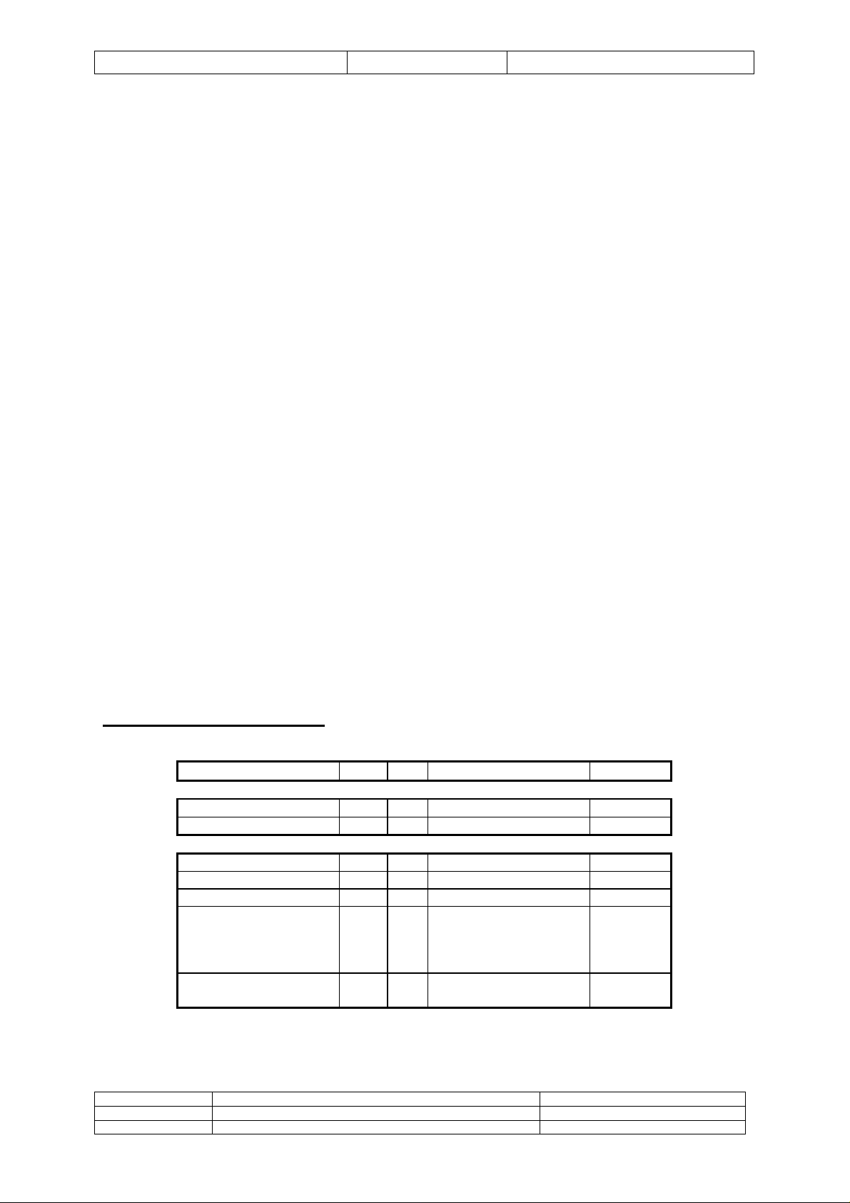
C44 Memory Map Summary
Address A20 A4 Function Strobe
(00)30 0000
(70)00 0000
(80)00 0000
(80)10 0000
(80)20 0000+nn
(80)20 0020
(80)30 0000
Local SRAM LSTRB0
ID ROM LSTRB0
0 x Global SRAM STRB0
1 x I2C STRB1
0 0 ADC/DAC nn STRB1
0 1 W:LED & I2C control
STRB1
R:Status,
bit 0 - interrupt status
bit 1 - left/right status
1 x W: Set FPGA PROG
STRB1
R: Clr FPGA PROG
Document Name: SMT326 Ugv2.doc Original Date: 08/11/97
Product Name: SMT326 Revision Date: 08/26/99
Author: Graeme Parker – Fabio Ancona
Page 9

Release Page 9 of 24 SMT326 DSP PC/ISA System User Guide
Interface Logic
A small FPGA is used to provide all interface functions from the PC-ISA bus. This device performs
the functions necessary for a 'C44 communication port interface. The FPGA is loaded at power on
from a small serial ROM. All features of the FPGA can be customised by re-configuring this.
Communication Port Interface
An eight bit interface to the 'C44 is provided for by this device. Four bytes must be
transferred for each 32 bit word that is to be transferred to or from the 'C44. The 'C44
communications ports only deal with 32 bit quantities, although the data is transferred as
bytes.
This interface is compatible with the SMT300 and SMT322 and can thus support existing
operating systems such as 3L (TISLINK=SMT300,io:300).
Three registers reside inside this interface for the control of data transfers.
Link Reset / NMI
This register is accessed at PC I/O address 0x30C.
Asserting bit 0 of this register will put the 'C44 into reset.
Asserting bit 1 of this register will assert the NMI signal to the 'C44.
Link Status
The interface status can be determined by reading this register. It is accessed at PC
I/O address 0x304.
If bit 7 returns a '1' then data can be written to the link data register for transmission
to the 'C44 communications port. If bit 7 returns a '0', then the link data register is
full.
If bit 6 returns a '1' then data can be read from the link data register (this data is the
most recently transmitted word from the 'C44 down its communications port). If bit 6
returns a '0' then no data is available.
Link Data
Data from the PC is written here for transferral to the 'C44. It is accessed at PC I/O
address 0x30A.
The least significant byte must be written first. When all four bytes have been
written, the interface logic will transfer the whole 32 bit word to the 'C44. Bit 7 of the
link status register need only be read once per 4 bytes. Transfers must be in
multiples of 4 bytes.
Data from the 'C44 is available here for reading by the PC. The least significant byte
is read first. Transfers must be in multiples of 4 bytes. When bit 6 of the link status
register returns a '1', four bytes may be read without reading the link status register
again.
Using this polled data transfer mechanism, a data rate of approx. 350k bytes/s can
be achieved. This is due mainly to the limitation of the PC-ISA bus.
Document Name: SMT326 Ugv2.doc Original Date: 08/11/97
Product Name: SMT326 Revision Date: 08/26/99
Author: Graeme Parker – Fabio Ancona
Page 10

Release Page 10 of 24 SMT326 DSP PC/ISA System User Guide
PC I/O Map Summary
I/O Address Function Comment
0x300-1
0x302-3
0x304
0x30A
0x30C
0x30E
0x30F
Link control / status bit 7 = output channel ready
bit 6 = input data available
Link data
Link reset / NMI bit 0 = reset to 'C44
bit 1 = NMI to 'C44
Jumpers
Jumper number Function
JP1 Short these two pins to produce an external reset.
JP2 Selects the ‘C44 boot mode. IN : comm port, OUT :
boot ROM.
JP3 Selects PC interface configuration mode. Right : serial
PROM, left : download cable. DO NOT CHANGE.
JP4 PEROM (boot ROM + ID ROM) write enable when IN.
Write protected when OUT.
JP5 Selects the XC9536 configuration mode. OUT :
normal, IN : via HDR2 (JTAG). DO NO CHANGE.
CV10 series Micro-miniature Coaxial Connector
It enables hoghly densed package in wireles terminal equipment and various hhigh-frequency
equipment.
General Specifications:
Characteristic Impedance 50 Ohms
Applicable frequency DC ~ 3 GHz
V.S.W.R. 1.3 max
Dielectric Withstanding Voltage 500 VAC r.m.s.
Insulation Resistance 500 Mohms
Contact Resistance
Center conductor:
Outer conductor:
Operating temperature From -40 C to +85 C
45 mOhms max
15 mOhms max
Reference:
Japan Aviation Electronics Ind. Ltd.
Document Name: SMT326 Ugv2.doc Original Date: 08/11/97
Product Name: SMT326 Revision Date: 08/26/99
Author: Graeme Parker – Fabio Ancona
Page 11

Release Page 11 of 24 SMT326 DSP PC/ISA System User Guide
Application Engineering Dept. – Connector Sales Promotion Div.
Aobadai Ishibashi Bldg. 1-19, Aobadai 3-chome, Meguro-ku Tokyo, Japan 153
Phone: 03-3780-2897 Fax: 03-3780-2884
Document Name: SMT326 Ugv2.doc Original Date: 08/11/97
Product Name: SMT326 Revision Date: 08/26/99
Author: Graeme Parker – Fabio Ancona
Page 12

Release Page 12 of 24 SMT326 DSP PC/ISA System User Guide
Connector Numbering
The DAC outputs are labelled as follows;-
Channel FPGA address FPGA address Channel
OUT0 80200010 80200018 OUT16
OUT1 80200000 80200008 OUT17
OUT2 80200011 80200019 OUT18
OUT3 80200001 80200009 OUT19
OUT4 80200012 8020001A OUT20
OUT5 80200002 8020000A OUT21
OUT6 80200013 8020001B OUT22
OUT7 80200003 8020000B OUT23
OUT8 80200014 8020001C OUT24
OUT9 80200004 8020000C OUT25
OUT10 80200015 8020001D OUT26
OUT11 80200005 8020000D OUT27
OUT12 80200016 8020001E OUT28
OUT13 80200006 8020000E OUT29
OUT14 80200017 8020001F OUT30
OUT15 80200007 8020000F OUT31
The DAC inputs are labelled as follows;-
Channel FPGA address FPGA address Channel
IN0 80200000 80200008 IN16
IN1 80200010 80200018 IN17
IN2 80200001 80200009 IN18
IN3 80200011 80200019 IN19
IN4 80200002 8020000A IN20
IN5 80200012 8020001A IN21
IN6 80200003 8020000B IN22
IN7 80200013 8020001B IN23
IN8 80200004 8020000C IN24
IN9 80200014 8020001C IN25
IN10 80200005 8020000D IN26
IN11 80200015 8020001D IN27
IN12 80200006 8020000E IN28
IN13 80200016 8020001E IN29
IN14 80200007 8020000F IN30
IN15 80200017 8020001F IN31
Document Name: SMT326 Ugv2.doc Original Date: 08/11/97
Product Name: SMT326 Revision Date: 08/26/99
Author: Graeme Parker – Fabio Ancona
Page 13

Release Page 13 of 24 SMT326 DSP PC/ISA System User Guide
Example Code
This example code shows how to capture all 32 channels (individually). Note that the data is right
shifted 4 bits purely to convert it into a 16 bit sample. Also note that the sampling of the channels is
performed in two parts (left and right). When interrupts are used to trigger the sampling, a single
interrupt channel is asserted for the left and right channels. Thus an interrupt based system will have
to synchronise with the left/right status before enabling interrupts.
fpga =(unsigned long *)0x80200000;
for(channel=0;channel!=16;channel++) {
for(i=0;i!=250;i++) {
while( ((*status) & 0x02) != 0);
sample[channel][i]=( (*fpga) >>4 )&0x0ffff;
while( ((*status) & 0x02) == 0);
}
fpga++;
}
for(channel=16;channel!=32;channel++) {
for(i=0;i!=250;i++) {
while( ((*status) & 0x02) != 2);
sample[channel][i]=( (*fpga) >>4 )&0x0ffff;
while( ((*status) & 0x02) == 2);
}
fpga++;
}
Document Name: SMT326 Ugv2.doc Original Date: 08/11/97
Product Name: SMT326 Revision Date: 08/26/99
Author: Graeme Parker – Fabio Ancona
Page 14

Release Page 14 of 24 SMT326 DSP PC/ISA System User Guide
Test Code
Test both a ADC channel and a DAC channel
This first example shows how to test input/output channels. This particular code reads the ADC
channel 1 (IN1) and writes to DAC channel 0 (OUT0)
-------------------------------------------------------------------------------------------------------------------------------------/* SMT326 test program: Reads the ADC channel 1 (IN1) and writes to DAC channel 0 (OUT0) */
#include <stdio.h>
#include <c40reg.h>
#include <math.h>
volatile unsigned long *i2c_s1, *i2c_sn;
volatile unsigned long *fpga, *fpgain, *fpgaout, *prog, *status;
volatile int delay,adc_word;
int i,j,t,temp,ctrl_byte,sample, channel, outadd, mask;
main(int argc,char *argv[])
{
prog =(unsigned long *)0x80300000;
fpga =(unsigned long *)0x80200000;
i2c_s1=(unsigned long *)0x80100001;
i2c_sn=(unsigned long *)0x80100000;
/* Setup the I2C interface device */
printf("Setting up I2C interface\n");
*i2c_s1=0x80; /* select own address regsiter */
for(i=0;i!=8;i++);
*i2c_sn=0x55; /* set own address = 0x55 */
for(i=0;i!=8;i++);
*i2c_s1=0xa0; /* select register S2 (clock register) */
for(i=0;i!=8;i++);
*i2c_sn=0x1c; /* set clock = 12MHz */
for(i=0;i!=8;i++);
*i2c_s1=0x10; /* select interrupt vector register */
*i2c_s1=0x80;
for(i=0;i!=175;i++);
*i2c_sn=0x55; /* set own address = 0xff */
for(i=0;i!=175;i++);
*i2c_s1=0xa0;
for(i=0;i!=175;i++);
*i2c_sn=0x1c; /* set SCL=90kHz, ext clk=12MHz */
for(i=0;i!=175;i++);
*i2c_s1=0xc1; /* idle / sda,acl high / ack / serial on */
for(i=0;i!=175;i++);
Document Name: SMT326 Ugv2.doc Original Date: 08/11/97
Product Name: SMT326 Revision Date: 08/26/99
Author: Graeme Parker – Fabio Ancona
Page 15

Release Page 15 of 24 SMT326 DSP PC/ISA System User Guide
while(((temp=(*i2c_s1)&0x01))==0) {
for(i=0;i!=175;i++);
}
/*
Enable I2C mux to point to Codec 0
Set LED=5
*/
fpga+=32; /* point to control register */
*fpga=0x85;
/* Initialise Codec via I2C */
for(channel=0;channel!=8;channel++) {
*fpga=0x85+(channel<<4);
/* printf("ch %d\n",channel);*/
for(delay=0;delay!=175;delay++);
i2c_send_address(0x20,0);
i2c_write(1);
i2c_write(0x00);
i2c_stop();
i2c_send_address(0x20,0);
i2c_write(2);
i2c_write(0x00);
i2c_stop();
i2c_send_address(0x20,0);
i2c_write(3);
i2c_write( 00);
i2c_stop();
i2c_send_address(0x20,0);
i2c_write(4);
i2c_write( 00);
i2c_stop();
ctrl_byte=9;
i2c_send_address(0x20,0);
i2c_write(5);
i2c_write(ctrl_byte);
i2c_stop();
i2c_send_address(0x20,0);
i2c_write(0x80);
i2c_restart(0x21,0);
temp=*i2c_sn; /* discard 1st byte */
temp=i2c_read(1);
for(delay=0;delay!=175;delay++);
i2c_stop();
Document Name: SMT326 Ugv2.doc Original Date: 08/11/97
Product Name: SMT326 Revision Date: 08/26/99
Author: Graeme Parker – Fabio Ancona
Page 16

Release Page 16 of 24 SMT326 DSP PC/ISA System User Guide
i2c_send_address(0x22,0);
i2c_write(1);
i2c_write(0x00);
i2c_stop();
i2c_send_address(0x22,0);
i2c_write(2);
i2c_write(0x00);
i2c_stop();
i2c_send_address(0x22,0);
i2c_write(3);
i2c_write( 00);
i2c_stop();
i2c_send_address(0x22,0);
i2c_write(4);
i2c_write( 00);
i2c_stop();
ctrl_byte=0x89;
i2c_send_address(0x22,0);
i2c_write(5);
i2c_write(ctrl_byte);
i2c_stop();
i2c_send_address(0x22,0);
i2c_write(0x80);
i2c_restart(0x23,0);
for(delay=0;delay!=175;delay++);
temp=*i2c_sn; /* discard 1st byte */
for(delay=0;delay!=175;delay++);
temp=i2c_read(1);
for(delay=0;delay!=175;delay++);
i2c_stop();
}
/* Generate IACK */
asm(" push ar0 ");
asm(" ldhi 7000h,ar0 ");
asm(" iack *ar0 ");
asm(" pop ar0 ");
j=0;
fpga =(unsigned long *)0x80200000;
status=(unsigned long *)0x80200020;
printf("\n\nEnter input channel number.\n");
printf("Output will appear on that output channel\n");
scanf("%d",&channel);
if (channel>15){
Document Name: SMT326 Ugv2.doc Original Date: 08/11/97
Product Name: SMT326 Revision Date: 08/26/99
Author: Graeme Parker – Fabio Ancona
Page 17

Release Page 17 of 24 SMT326 DSP PC/ISA System User Guide
outadd=-16;
mask = 2;}
else{
outadd=16;
mask=0;}
printf("Default mask = %d, choose 2 or 0\n",mask);
scanf("%d",&mask);
fpga =(unsigned long *)0x80200000+channel;
printf("Input on %8X, output on %8x\n\n", fpga, (fpga+outadd));
printf("Starting...\n");
while(1) {
while( ((*status) & 0x02) != mask)
/* printf("status reg1 = 0x%8X\n",*status);*/
sample= (*fpga);
*(fpga+outadd) = sample;
/* printf("status reg2 = 0x%8X\n",*status);*/
while( ((*status) & 0x02) == mask);
}
}
/*******************************************************************************
Functions
*******************************************************************************/
i2c_send_address(int add,int setnack)
{
volatile int delay;
*i2c_s1 = 0x40;
for(delay=0;delay!=175;delay++);
while((*i2c_s1 & 1) == 0);
*i2c_sn = add;
for(delay=0;delay!=175;delay++);
for(delay=0;delay!=175;delay++);
if(setnack == 1) *i2c_s1 = 0x44;
else *i2c_s1 = 0x45;
for(delay=0;delay!=175;delay++);
while((*i2c_s1 & 0x80) == 0x80);
for(delay=0;delay!=175;delay++);
}
i2c_read(int setnack)
{
volatile int delay;
for(delay=0;delay!=175;delay++);
while((*i2c_s1 & 0x80) == 0x80);
for(delay=0;delay!=175;delay++);
if(setnack == 1) *i2c_s1 = 0x40;
for(delay=0;delay!=175;delay++);
return(*i2c_sn);
}
i2c_stop()
{
volatile int delay;
*i2c_s1 = 0xc3;
Document Name: SMT326 Ugv2.doc Original Date: 08/11/97
Product Name: SMT326 Revision Date: 08/26/99
Author: Graeme Parker – Fabio Ancona
Page 18

Release Page 18 of 24 SMT326 DSP PC/ISA System User Guide
for(delay=0;delay!=175;delay++);
while((*i2c_s1 & 0xff) != 0x81); /* printf("%02X\n",*i2c_s1 & 0xff); */
for(delay=0;delay!=175;delay++);
}
i2c_write(int data)
{
volatile int delay;
*i2c_sn = data;
for(delay=0;delay!=175;delay++);
while((*i2c_s1 & 0x80) == 0x80);
for(delay=0;delay!=175;delay++);
}
i2c_restart(int address, int setnack)
{
volatile int delay;
while((*i2c_s1 & 0x80) == 0x80);
if(setnack == 1) *i2c_s1 = 0x44;
else *i2c_s1 = 0x45;
for(delay=0;delay!=175;delay++);
*i2c_sn=address;
for(delay=0;delay!=175;delay++);
while((*i2c_s1 & 0x80) == 0x80);
for(delay=0;delay!=175;delay++);
}
Document Name: SMT326 Ugv2.doc Original Date: 08/11/97
Product Name: SMT326 Revision Date: 08/26/99
Author: Graeme Parker – Fabio Ancona
Page 19

Release Page 19 of 24 SMT326 DSP PC/ISA System User Guide
Test a DAC channel
This second example shows how to test a DAC channel. The program generates a sine wave that it
will be the digital input to the DAC to test.
/* SMT326 DAC channel 0 test program */
#include <stdio.h>
#include <c40reg.h>
#include <math.h>
volatile unsigned long *i2c_s1, *i2c_sn;
volatile unsigned long *fpga, *prog, *status;
volatile int delay;
int i,j,t,temp,ctrl_byte, channel, mask;
char ch;
int sin_table[256];
int f1,f2,f3,f4;
int i1,i2,i3,i4;
main(int argc,char *argv[])
{
for(i=0;i!=256;i++) sin_table[i]=(int)(000+256*(sin(3.14*i/128)));
prog =(unsigned long *)0x80300000;
fpga =(unsigned long *)0x80200000;
i2c_s1=(unsigned long *)0x80100001;
i2c_sn=(unsigned long *)0x80100000;
/* Setup the I2C interface device */
printf("Setting up I2C interface\n");
*i2c_s1=0x80; /* select own address regsiter */
printf("ai2c_s1=%x\n",*i2c_s1);
for(i=0;i!=8;i++);
printf("ai2c_s1=%x\n",*i2c_s1);
*i2c_sn=0x55; /* set own address = 0x55 */
for(i=0;i!=8;i++);
printf("si2c_sn1=%x\n",*i2c_sn);
*i2c_s1=0xa0; /* select register S2 (clock register) */
printf("di2c_s1=%x\n",*i2c_s1);
for(i=0;i!=8;i++);
printf("di2c_s1=%x\n",*i2c_s1);
*i2c_sn=0x1c; /* set clock = 12MHz */
for(i=0;i!=8;i++);
printf("fi2c_sn=%x\n",*i2c_sn);
*i2c_s1=0x10; /* select interrupt vector register */
printf("mi2c_s1=%x\n",*i2c_s1);
*i2c_s1=0x80;
printf("qi2c_s1=%x\n",*i2c_s1);
for(i=0;i!=1000;i++);
printf("qi2c_s1=%x\n",*i2c_s1);
Document Name: SMT326 Ugv2.doc Original Date: 08/11/97
Product Name: SMT326 Revision Date: 08/26/99
Author: Graeme Parker – Fabio Ancona
Page 20

Release Page 20 of 24 SMT326 DSP PC/ISA System User Guide
*i2c_sn=0x55; /* set own address = 0xff */
for(i=0;i!=1000;i++);
printf("wi2c_sn=%x\n",*i2c_sn);
*i2c_s1=0xa0;
for(i=0;i!=1000;i++);
printf("ei2c_s1=%x\n",*i2c_s1);
*i2c_sn=0x1c; /* set SCL=90kHz, ext clk=12MHz */
for(i=0;i!=1000;i++);
printf("ri2c_sn=%x\n",*i2c_sn);
*i2c_s1=0xc1; /* idle / sda,acl high / ack / serial on */
for(i=0;i!=1000;i++);
printf("ti2c_s1=%x\n",*i2c_s1);
while(((temp=(*i2c_s1)&0x01))==0) {
for(i=0;i!=1000;i++);
}
fpga+=32; /* point to control register */
for(channel=0;channel!=8;channel++) {
*fpga=0x85+(channel<<4);
printf("ch %d\n",channel);
for(delay=0;delay!=100000;delay++);
printf("1\n");
i2c_send_address(0x20,0);
i2c_write(1);
i2c_write(0x00);
i2c_stop();
i2c_send_address(0x20,0);
i2c_write(2);
i2c_write(0x00);
i2c_stop();
i2c_send_address(0x20,0);
i2c_write(3);
i2c_write( 00);
i2c_stop();
i2c_send_address(0x20,0);
i2c_write(4);
i2c_write( 00);
i2c_stop();
ctrl_byte=9;
i2c_send_address(0x20,0);
i2c_write(5);
i2c_write(ctrl_byte);
i2c_stop();
i2c_send_address(0x20,0);
i2c_write(0x80);
i2c_restart(0x21,0);
temp=*i2c_sn; /* discard 1st byte */
temp=i2c_read(1);
for(delay=0;delay!=100000;delay++);
Document Name: SMT326 Ugv2.doc Original Date: 08/11/97
Product Name: SMT326 Revision Date: 08/26/99
Author: Graeme Parker – Fabio Ancona
Page 21

Release Page 21 of 24 SMT326 DSP PC/ISA System User Guide
i2c_stop();
i2c_send_address(0x22,0);
i2c_write(1);
i2c_write(0x00);
i2c_stop();
i2c_send_address(0x22,0);
i2c_write(2);
i2c_write(0x00);
i2c_stop();
i2c_send_address(0x22,0);
i2c_write(3);
i2c_write( 00);
i2c_stop();
i2c_send_address(0x22,0);
i2c_write(4);
i2c_write( 00);
i2c_stop();
ctrl_byte=9;
i2c_send_address(0x22,0);
i2c_write(5);
i2c_write(ctrl_byte);
i2c_stop();
i2c_send_address(0x22,0);
i2c_write(0x80);
i2c_restart(0x23,0);
for(delay=0;delay!=100000;delay++);
temp=*i2c_sn; /* discard 1st byte */
for(delay=0;delay!=100000;delay++);
temp=i2c_read(1);
for(delay=0;delay!=100000;delay++);
i2c_stop();
}
/* Generate IACK */
asm(" push ar0 ");
asm(" ldhi 7000h,ar0 ");
asm(" iack *ar0 ");
asm(" pop ar0 ");
j=0;
printf("\n\nEnter channel number : ");
scanf("%d",&channel);
fpga =(unsigned long *)0x80200000+channel;
status=(unsigned long *)0x80200020;
Document Name: SMT326 Ugv2.doc Original Date: 08/11/97
Product Name: SMT326 Revision Date: 08/26/99
Author: Graeme Parker – Fabio Ancona
Page 22

Release Page 22 of 24 SMT326 DSP PC/ISA System User Guide
if(channel < 16) mask=2;
else mask=0;
/*
Generate a DAC output using 4 freq inc's
Try 10,11,12,13 for an interesting output
*/
f1=f2=f3=f4=0;
/* printf("Enter freqs : ");
scanf("%d %d %d %d",&i1,&i2,&i3,&i4);
*/
i1=10;
i2=11;
i3=12;
i4=13;
while(1) {
while( ((*status) & 0x02) != mask); /* wait for next sample clock transition */
*fpga=((sin_table[f1]+sin_table[f2]+sin_table[f3]+sin_table[f4]) << 9);
/* printf("%08lX\n",((sin_table[f1]+sin_table[f2]+sin_table[f3]+sin_table[f4]) << 9));*/
f1+=i1;
f2+=i2;
f3+=i3;
f4+=i4;
f1=f1%256;
f2=f2%256;
f3=f3%256;
f4=f4%256;
while( ((*status) & 0x02) == mask); /* wait for next sample clock transition */
}
}
/*******************************************************************************
Functions
*******************************************************************************/
i2c_send_address(int add,int setnack)
{
volatile int delay;
*i2c_s1 = 0x40;
printf("1i2c_s1=%x\n",*i2c_s1);
for(delay=0;delay!=10000;delay++);
while((*i2c_s1 & 1) == 0);
*i2c_sn = add;
for(delay=0;delay!=10000;delay++);
for(delay=0;delay!=10000;delay++);
if(setnack == 1) *i2c_s1 = 0x44;
else *i2c_s1 = 0x45;
for(delay=0;delay!=10000;delay++);
printf("2i2c_s1=%x\n",*i2c_s1);
while((*i2c_s1 & 0x80) == 0x80){
printf("3i2c_s1=%x\n",*i2c_s1);
ch=getchar();
}
printf("5\n");
Document Name: SMT326 Ugv2.doc Original Date: 08/11/97
Product Name: SMT326 Revision Date: 08/26/99
Author: Graeme Parker – Fabio Ancona
Page 23

Release Page 23 of 24 SMT326 DSP PC/ISA System User Guide
for(delay=0;delay!=10000;delay++);
}
i2c_read(int setnack)
{
volatile int delay;
for(delay=0;delay!=10000;delay++);
while((*i2c_s1 & 0x80) == 0x80);
for(delay=0;delay!=10000;delay++);
if(setnack == 1) *i2c_s1 = 0x40;
for(delay=0;delay!=10000;delay++);
return(*i2c_sn);
}
i2c_stop()
{
volatile int delay;
*i2c_s1 = 0xc3;
for(delay=0;delay!=10000;delay++);
while((*i2c_s1 & 0xff) != 0x81); /* printf("%02X\n",*i2c_s1 & 0xff); */
for(delay=0;delay!=10000;delay++);
}
i2c_write(int data)
{
volatile int delay;
*i2c_sn = data;
for(delay=0;delay!=10000;delay++);
while((*i2c_s1 & 0x80) == 0x80);
for(delay=0;delay!=10000;delay++);
}
i2c_restart(int address, int setnack)
{
volatile int delay;
while((*i2c_s1 & 0x80) == 0x80);
if(setnack == 1) *i2c_s1 = 0x44;
else *i2c_s1 = 0x45;
for(delay=0;delay!=10000;delay++);
*i2c_sn=address;
for(delay=0;delay!=10000;delay++);
while((*i2c_s1 & 0x80) == 0x80);
for(delay=0;delay!=10000;delay++);
}
-------------------------------------------------------------------------------------------------------------------------------------
Document Name: SMT326 Ugv2.doc Original Date: 08/11/97
Product Name: SMT326 Revision Date: 08/26/99
Author: Graeme Parker – Fabio Ancona
Page 24

Release Page 24 of 24 SMT326 DSP PC/ISA System User Guide
How To DMA
To relieve the ‘C44 of any unnecessary burden of waiting for a new sample to be acquired, it is
possible (if a little complicated) to request that the ‘C44’s DMA controller perform the entire transfer
of samples into memory (or comm port) with only a single interrupt on completion.
The procedure would be to setup a series of 4 DMA operation (DMAOP) each one linking to the
following one, with DMA operation 4 linking to DMA operation 1.
DMAOP1 would synchronise to the FPGA interrupt IIOF0, have a source address pointing to
0x80200000 (FPGA source), destination address pointing to the required memory address (BUF), a
transfer length of 1, and a link pointer pointing to DMAOP2.
DMAOP2 would have no synchronisation, have a source address pointing to 0x80200001, destination
address of BUF+1, a transfer length of 15, and a link pointer pointing to DMAOP3.
DMAOP3 would synchronise to the FPGA interrupt IIOF0, have a source address pointing to
0x80200010 (FPGA source), destination address pointing to the required memory address (BUF+16),
a transfer length of 1, and a link pointer pointing to DMAOP4.
DMAOP4 would have no synchronisation, have a source address pointing to 0x80200011, destination
address of BUF+17, a transfer length of 15, a link pointer pointing to DMAOP1, and would set the
TCC bit (to enable an interrupt on completion).
In operation, the FPGA will generate an interrupt on IIOF0 for the left channel say, this will trigger
DMAOP1 to read and store the first channel. DMAOP2 will then start and read and store the next 15
channels. DMAOP3 is then started, which will wait for the next interrupt on IIOF0 (the right channels).
When this is received, DMAOP3 will read and store channel 16 and then start DMAOP4. DMAOP4
reads and stores the remaining 15 channels, generates an interrupt to the ‘C44 and reloads
DMAOP1.
When the ‘C44 receives its interrupt, the whole 32 channels will be stored at BUF.
Various simpler alternatives are available, including the ‘C44 responding to the left and right channel
interrupts, and performing the transfers itself.
Document Name: SMT326 Ugv2.doc Original Date: 08/11/97
Product Name: SMT326 Revision Date: 08/26/99
Author: Graeme Parker – Fabio Ancona
 Loading...