

Page 1

SMT107
User Manual
User Manual (QCF42); Version 3.0, 8/11/00; © Sundance Multiprocessor Technology Ltd. 1999
Page 2
Version 1.2 Page 2 of 16 SMT107 User Manual
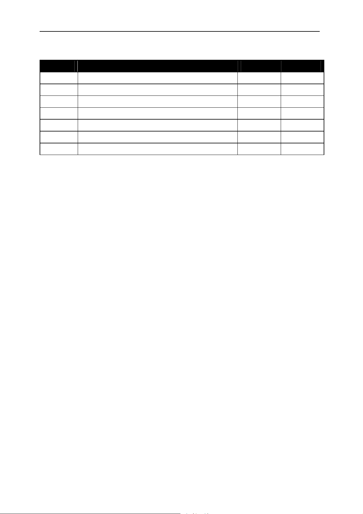
Revision History
Date Comments Engineer Version
20/04/01 Initial M.R. 1.0
24/11/05 Update information for CCS 3.1 M.A. 1.1
01/03/06 Update: Drivers location for CCS 3.1 SM 1.2
Page 3

Version 1.2 Page 3 of 16 SMT107 User Manual
Table of Contents
Revision History .......................................................................................................................2
Table of Contents.....................................................................................................................3
SMT107 PCMCIA (PC-CARD) JTAG Emulator .......................................................................4
Before You Start.......................................................................................................................5
Check the Contents..............................................................................................................5
PC System Requirements....................................................................................................5
Installation Instructions.............................................................................................................6
Hardware Installation............................................................................................................6
Microsoft Windows 95/98 Driver Installation ........................................................................7
Microsoft Windows NT4 Driver Installation.........................................................................10
Setting-up Code Composer................................................................................................12
Versions prior to 3.0 .......................................................................................................12
Version 3.0 and Later....................................................................................................15
Page 4

Version 1.2 Page 4 of 16 SMT107 User Manual
SMT107 PCMCIA (PC-CARD) JTAG Emulator
The SMT107 is a size II PCMCIA (PC-CARD16) Card with full XDS510-JTAG Emulator
capability built into it.
The emulator currently supports the TMS320C6000 family of DSP’s from Texas Instruments
and also Texas Instrument’s Code Composer Studio development and debugging software
environment.
The current basic package comes with PCMCIA Card, cable and device driver for Code
Composer Studio. The full package includes Code Composer Studio at a special bundled
price.
IF YOU EXPERIENCE ANY PROBLEMS OR HAVE ANY QUESTIONS REGARDING THE
SMT107 EMULATOR THEN CONTACT THE SMT107 SUPPORT TEAM ON:
support@attavionics.com
Page 5

Version 1.2 Page 5 of 16 SMT107 User Manual
Before You Start
Please take a few minutes to read this guide and acquaint yourself with both the installation
process and the features of your card. Installation is simple, but you must take care to follow
the instructions carefully.
Check the Contents
After opening and unpacking the box, you will find the following items:
1. SMT107 PCMCIA card,
2. SMT107 POD,
3. PCMCIA card cable (1m long),
4. JTAG cable (10cm long),
5. SMT107 Software Driver CD-ROM or Floppy Disk,
6. Installation Guide (this document).
PC System Requirements
In order to install the SMT107 and Code Composer for C6000, your PC will have to meet the
following requirements:
1. A 486 or later processor with a minimum of 512MB Ram,
2. 1.5GB free hard disk space. This is for a standard CCS3.1 Platinum installation,
3. Microsoft Windows 2000 or later (Windows XP is advised),
4. Code Composer 3.0 (or later) or Code Composer Studio 2.2x (or later),
5. A free PCMCIA 16 bit slot.
Page 6

Version 1.2 Page 6 of 16 SMT107 User Manual
Installation Instructions
If Code Composer for C6000 is not already installed on the host PC; install it now. Follow the
instructions provided by Texas Instruments.
Hardware Installation
Both the SMT107 PCMCIA card and the cables supplied with the SMT107 are keyed to
ensure they cannot be inserted incorrectly. Please ensure you are familiar with all these
connections before you attempt to install the hardware. Then follow the following procedure.
1. Remove the power from the target board,
2. Shutdown and power off your PC,
3. Insert the SMT107 card into a spare PCMCIA slot in your machine,
4. Connect the PCMCIA card cable to the PCMCIA card,
5. Connect the other end of the PCMCIA card cable to the SMT107 POD,
6. Connect the JTAG cable to the SMT107 POD,
7. Connect the other end of the cable to the JTAG header on the target, using the blocked
off pin to ensure correct alignment,
8. Reboot the PC,
9. Connect power to the target board,
Some operating systems (i.e. Microsoft Windows 95 & 98) allow you to insert PCMCIA cards
with the machine already switched on. This is permitted with the SMT107.
However, you must make sure that the SMT107 is installed and configured correctly
BEFORE you try to start Code Composer. Code Composer is not written to allow PCMCIA
cards to be inserted and removed whilst it is running.
For Microsoft Windows NT4 systems, the SMT107 has to be installed BEFORE you switch
the machine on. Windows NT4 is only able to recognise PCMCIA cards during the boot
sequence, and therefore the card must be inserted prior to booting
Page 7

Version 1.2 Page 7 of 16 SMT107 User Manual
Microsoft Windows 95/98 Driver Installation
Microsoft Windows 95 and 98 are so-called Plug-n-Play aware operating systems. This
means that they can automatically detect and configure new hardware as it is added to your
system. When rebooting the PC for the first time after installing the hardware (step 8 in the
Hardware Installation), Win95/98 will ask you to perform the following setup sequence.
1. When rebooting for the first time, the following screen will appear:
2. Insert the SMT107 Driver floppy or CD-ROM provided and Click Next.
3. Windows will search the floppy disk for a valid driver file, and the following screen will
appear:
If Windows does not find a valid driver on the disk, then use the “Other Locations” button
to browse for it.
Page 8

Version 1.2 Page 8 of 16 SMT107 User Manual
4. Click “Finish”, remove the SMT107 installation floppy and allow the computer to reboot.
5. Once the computer has rebooted then the installation can be checked by going to the
Start Menu and choosing Settings->Control Panel. Then double-click the “System” icon,
the “System Properties” window will appear. Select the “Device Manager” tab.
6. The card should be listed as a “JTAG Test Bus Controller” as shown above. Select the
device and then click the “Properties” button.
Page 9

Version 1.2 Page 9 of 16 SMT107 User Manual
7. The device properties window should appear. In the “General” tab check that the device
is working properly then select the “Resources” tab…
8. Make a note of the first I/O address (in this case 0x280) as this address will be required
later,
9. Click “OK” to close the properties window,
10. Click “OK” to close the System window,
11. Close the “Control Panel”,
12. Proceed to the Setting Up Code Composer Section of this manual.
Page 10

Version 1.2 Page 10 of 16 SMT107 User Manual
Microsoft Windows NT4 Driver Installation
Microsoft Windows NT4 is not a Plug-n-Play aware operating system, and will not
automatically detect and configure new hardware as it is added to your system. Therefore, it
is necessary for you to run the supplied installation program to configure your SMT107 to
work with Windows NT4. To do this, perform the following setup sequence.
1. Insert the SMT107 Driver floppy or CD-ROM provided and run a:\setup
2. The following screen will appear:
3. Allow the files to extract and the following screen will appear: Click “Next >”
4. Read the license agreement and click “Yes” to continue.
Page 11

Version 1.2 Page 11 of 16 SMT107 User Manual
5. The User Information screen will appear:
6. Enter your name and company and then enter the serial number of your SMT107 board,
this should be clearly marked on both the board itself and on the packaging. Now click
“Next >”. The driver installation will complete and you will be asked to restart the
computer.
7. Click “Finish”, remove the SMT107 installation floppy and allow the computer to reboot.
8. Once the computer has rebooted, proceed to the Setting Up Code Composer Section of
this manual.
NOTE: Whe n installing the SMT107 in a Windows NT4 systems, the Base IO address will
always be 0x240. This is due to a limitation in the support for PCMCIA cards under Windows
NT4. If another device is already using IO port 0x240, then it will be necessary to either
remove or disable that device in order to allow the SMT107 to work correctly.
Page 12

Version 1.2 Page 12 of 16 SMT107 User Manual
Setting-up Code Composer
Versions prior to 3.0
1. Start the “Setup CCStudio” program. Close the “Import Configuration” window which may
open automatically.
2. From the options on the right-most panel, choose “Install a Device Driver”.
3. The “Select Device Driver File” dialog will appear, choose the file “att107-6x.dvr” and click
“Open”.
4. The “Device Driver Properties” window will appear, enter a suitable name and description
to help identify the driver file.
5. Click “OK” the device will now be listed in the central panel of the Code Composer Setup
window.
Page 13

Version 1.2 Page 13 of 16 SMT107 User Manual
6. To select the SMT107 as the driver used by Code Composer, double-click the entry in
the central panel. Details of the SMT107 will appear in the right-most panel and the
“Board Properties” dialog will appear…
If you have a custom board data file for your target hardware link to it here, otherwise use the
default generated board data file and click “Next >” to move to the “Board Properties” screen.
7. In the I/O Port Value field enter the value you noted down from Section 13 of the Driver
Installation (eg. 0x280). Click “Next >” to move to the “Processor Configuration” screen.
Page 14

Version 1.2 Page 14 of 16 SMT107 User Manual
Follow the instructions on the dialog to add as many processors as there are on the
target board. Click “Finish”.
8. The device should now be listed in the “My System” directory on the left-most panel of
the Code Composer Setup screen. Use File->Save to save your changes and then File-
>Exit to complete the Setup procedure.
9. You can now start Code Composer in the normal way.
Page 15

Version 1.2 Page 15 of 16 SMT107 User Manual
Version 3.0 and Later
The device driver interface configuration has been changed for CCS version 3.0 and higher.
1. Copy the SMT107.dll from the disc to the {CCS_base}\drivers, {CCS_base}\cc\bin
and in C:\WINDOWS\system32 folders.
2. Copy the SMT107_XDS510_Connection.xml file from the disc to the
{CCS_base}\drivers\TargetDB\connections folder.
3. Start the CCS setup program and select the “create board” table in the middle pane
4. Select the “SMT107 XDS510 Emulator Connection” and press the now active “Add”
button. This will now open a configuration dialog box.
Page 16

Version 1.2 Page 16 of 16 SMT107 User Manual
5. Give the board a suitable name and press “Next”.
6. Change the configuration page so that the Emulator I/O port is 0x320 in this case
(note that is generally 0x240, please checking in the System properties for the POD
IO address). Then press “Finish”.
7. Then select a family of processors, and add them to the board configuration.
8. Save and Exit, and start code composer without forgetting to connect the target (in
the menu DEBUG of CCS).
 Loading...