

Outdoor Analogue Bullet Thermal camera
ZS-H350
User Manual

Table of Contents
1 Safety information
..........................................................................................................................................................3
2 Notice to User.................................................................................................................................................................4
3 Check List........................................................................................................................................................................5
4 Product description........................................................................................................................................................ 1
5 Product installation
........................................................................................................................................................ 2
5.1 Lightning protection
.................................................................................................................................................2
5.2 Cable.........................................................................................................................................................................2
5.3 Installation procedure..............................................................................................................................................4
5.4 Other related matters.............................................................................................................................................. 4
5.5 Warning
....................................................................................................................................................................4
5.6 Other instructions
.................................................................................................................................................... 5
6 Installation environment
................................................................................................................................................6
6.1 Installation environment requirements................................................................................................................... 6
6.2 Installation steps...................................................................................................................................................... 6
6.3 Verifying Camera......................................................................................................................................................7
6.4 Technical Parameters.............................................................................................................................................10
7 Warranty
...................................................................................................................................................................... 11
7.1 Warranty scope......................................................................................................................................................11
7.2 Condition................................................................................................................................................................11
7.3 Return back............................................................................................................................................................ 11
7.4 Special cases
...........................................................................................................................................................12
Appendix
.............................................................................................................................................................................13
1. Introduction to configuration of thermal camera
....................................................................................................13
2. Failures and solutions
............................................................................................................................................ 200

1 Safety information
Non-professional personals should not disassemble, make any change of this cloud platform.
Please read this manual carefully before taking operation. Please be noticed that any changes
of this manual our company is not obliged to make individual inform
DO NOT operate camera when it is switched on, in order to avoid any damage of PTZ in the
case of mis-operation.
Since the PTZ platform contains many precision mechanical and optical devices, please prevent
heavy pressure, strong vibration, and any other incorrect operation on this product, otherwise
may cause damage.
Please DO NOT use this product beyond the temperature limit, humidity or specified input
voltage.

2 Notice to User
1. Calibration
2. Updates of Documentation
Our manuals are updated without schedule, and we also issue product-critical notifications of
changes on a regular basis.
To access the latest manuals and notifications, please visit by the address
http://www.suncti.com/en/download?category=28
3. Customer help
Please contact us for your problems according to information described at site:
http://www.suncti.com/en/contactus
4. Convention used in this manual
a) “Our Company” stands for SunCreative (Zhejiang) Technologies Inc.
b) A “Hint” is for a help and more explanation for related operation.
c) A “Notice” or “Warning” is a prompt for potential risk. In the case of ignorance, it may
cause damage, loss of data, under-performance of equipment or other unpredictable
result.
d) A “Remark” is useful additional information for this article.
e) A “Important” shows important information for operating, using this camera.

3 Check List
Please check whether these parts listed below is completed within the box when it is opened.
In the case of any missing of accessories, please don’t be hesitated to contact with your dealers, or
directly to us (overseasales@suncti.com ).
Name of the accessories
Quantity
Outdoor Analogue Bullet Thermal
camera H350
1
Attachment bag
1
Certificate of approval
1
User Manual
1

1
4 Product description
Powerful embedded intelligent analysis algorithm makes region intrusion detection, line
crossing detection, moving path tracking, target enhancement and other intelligent analysis
functions realized in the device.
Leading thermal imaging procession algorithm: IDE (Image Details Enhancement algorithm),
HDR (High Dynamic Range algorithm: sea-sky mode, sky-earth mode)
Embedded high temperature alarm module, accurately pre-alarms the fire source in time
based on the leading temperature alarming algorithm. The pre-alarming grades are
adjustable; applicable for the need of fire pre-alarming in different scenes.
Applicable under extreme bad weather (including complete darkness, rain, snow, smog and
etc.).
IP66 protection, wall-mounting bracket available for standard configuration; PTZ platform is
optional ;
Powered by complete functions and interfaces, standardized security interface design;
PELCO protocol compliant; easy for system integration.
Impressive appearance, small and portable, easy for installation and maintenance.
2
5 Product installation
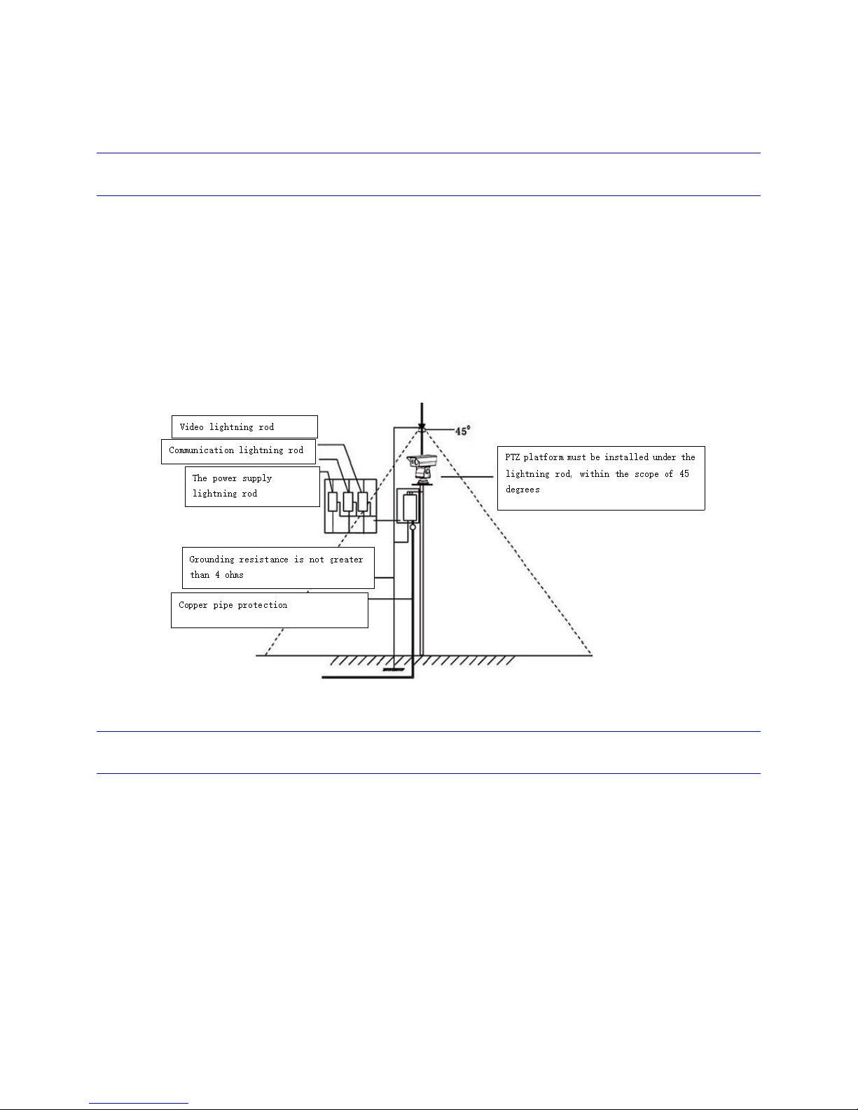
5.1 Lightning protection
When this product is installed in a high independent position, lightning protection measures must be
taken (as shown in the figure below). Please make sure to keep enough distance between RS - 485 and
video signal with high voltage pressure device or cable, when necessary, it is also important to apply
lightning protection, anti-surge protection measures, etc. This product must be installed according to
international GB50198 (Civil closed circuit monitoring TV system engineering and technical specification)
standard for reliable ground lightning protection, otherwise possible damage may be caused to the
product. The resistance between ground point and product should be less than 4Ω.
5.2 Cable
This product is packed along with an adapter with input of AC220V±10% and it must be grounded
safely. In the case of unstable voltage input, please take necessary operations before connecting to the
power supply in order to ensure that the product can work under working condition.
Please have notice that the switching power supply is not waterproof, therefore it should be
installed in the electrical distribution box under operating temperature between - 40 ℃ ~ + 60 ℃.
In order to avoid insufficient power supply voltage and normal operation of the equipment, the
distance between the power and equipment cannot be more than the values specified bellow:
Cable preparation:
1. Ethernet cable: Comply with standard ANSI/EIA/TIA - 568 - a/B and ISO/D , running a 10 m / 100
MBPS Ethernet 5 classes or super 5 unshielded twisted pair cable. Cable length should not be more than

3
100 meters.
2. AC24V power cable: Should be capable with the power loaded. The following table is for your
reference:
Table 2-1
Notice: It is suggested to use at least the AC24V power with maximum input power of 120 W.
3. Video cable: A typical cable with 75 pical cable within reference and 95% of the bronze shield coaxial
cable should be used. Related models and transmission data can be referred from table 2-2. When the
distance exceeds some value, it is suggested to add a video compensator.
Model
75-3
75-5
75-7
Transmission
distance(m)
220
300
450
Table 2-2
4. RS485 and alarm output lines: A shielded twisted-pair cable should be used, and its shield must
connect to GND in order to avoid interference or transmission anomaly. When using shielded
twisted-pair cable which has the bare wire line diameter of 0.56 mm, the baud rate and transmission
distance can be referred to table 2-3.
Table 2-3
Baud rate
2400
4800
9600
19200
Transmission
distance(m)
1800
1200
800
600
Power (Watt)
Distance (M)
Wire diameter (mm)
0.80
1.00
1.25
2.00
60
142236
91
70
121931
78
80
101727
68
90
91524
61
100
81321
55
110
71219
49
120
71117
45
130
61016
42
140
6915
39
150
5914
36
160
5813
34

4
5.3 Installation procedure
Please avoid deploying near any power lines, strong magnetic environment to prevent any
abnormality after installation.
Please install this product on platform with enough bearing support. Please avoid using unstable
platform, because it may cause image dithering and the monitoring results may be affected.
The product installation position should be considered in the process of rotation to make sure
that it will not disturb with surrounding objects which may cause damage on the product. To
achieve the best performance of monitoring, it is suggested that this product should be installed
at least two meters above ground, and after installation the related warning labels should also be
set up.
The installation direction should follow the arrow, which is shown at the side face of product.to
make sure the back-end PTZ control direction corresponds with PTZ rotation direction.
When connecting the bottom of the PTZ platform output cables, please in strict follow with the
procedure in the <<Product manual>> or the labels on the cable, and also make sure to
complete the waterproof process of the contact points.
After the installation of the product, do not force to turn the PTZ platform, which may cause
damage to PTZ platform system.
5.4 Other related matters
The product contains precise optical and electronic devices, during transportation and installation;
please keep preventing stress, severe vibration and any incorrect operation methods to avoid any
damage to the product.
Don't use and operate this product beyond limit of temperature, humidity or other of power
supply specifications.
Don't wash with strong or any abrasive detergent. A dry and soft cloth is recommended to use
when cleaning up. If the dirt is not easy to remove, you can use neutral detergent and then use
the dry cloth to wipe the product gently.
Since the window glass has been processed with special protection layer, when the visible light
camera and thermal imaging window are dirty, please wipe it with special lens paper.
5.5 Warning
Installation and maintenance of the products should be conducted by professional service personnel,
and only to use parts or accessories supplied by the manufacturer.
No matter the product is at work status or not, please don't put the camera under the sun or in front
of a strong lighting object, don't direct the camera to any bright stationary object (such as the sun) to
avoid any damage to the camera sensor.

5
5.6 Other instructions
Any information in this manual is for reference only. For details please refer to the final product. In
the case of any problems, please contact the supplier or the company customer service directly.
Some data provided in this manual may be deviated from actual measured values because of the
unstable real environment. If you have any question or arguments, please refer to our company for
final explanation.
Any damage or failure that is caused by operations not in accordance with procedures in this
guidance shall be bear by purchaser.

6
6 Installation environment
6.1 Installation environment requirements
Do not use in moisture or high temperature environment, keep in good ventilation, avoid installation
under violent vibration, keep it away from heating device as far as possible.
It is recommended to use under the following environment conditions:
Temperature:-40 ~ +60 ℃;
Humidity: 0% ~ 90%RH (No condensation).
6.2 Installation steps
1. Shape dimension figure:
2. Installation requirements: Please read carefully of the contents of this user manual, after
confirming your equipment system is in good condition, follow the steps below, and also keep
Your hands clean and dry.
a. Broke and open the packing cases;
b. Make integrity checking for items.
c. Get out each item that is needed for installation.
d. Connect the cable according to the actual requirement (such as power line, control line,
alarming wire and etc.).
e. Connect the power supply.
f. Please read the following attention items(from i to iv) carefully, if you have any questions,
please contact us.

7
Attentions:
i. Before breaking and opening each packing box please make sure that the items are in
accordance with the checking list.
ii. Before installation, please read carefully the user manual.
iii. When installing a network camera, please be sure to close all the AC power.
iv. Check the voltage of power supply: Avoid the voltage mismatch of the power supply
with product specifications.
v. Connect the power supply
g. After the installation is completed, the power-on test could be started. Each time after
power-on, PTZ platform will make self-check to ensure that everything is OK. After the
test, the screen will switch to the current video image. Only after when the power-on
test is completed, the PTZ platform could be operated. For some abnormalities that have
been found during the process of self-check, You may refer to the appendix to fix and
maintain them. For other instructions about the operation of this product, please refer
the attached discs and find the related content.
6.3 Verifying Camera
Insert the compact disk, run the software in it, then connect the switches to the computer(more than
one camera can connect with computer through switch). The SDAP software will automatically search
all equipment within the local area network (LAN), and online detection will be made to show all normal
connected cameras.
Important:
The infrared thermal imaging camera camera:192.168.83.27.
The default user name/password is: admin/admin12345.
Warning:
You should change this default user name and password as soon as possible in order to avoid any
hostile attack, and save the pairs in a safe place
Based on the IP address searched out, it is necessary to add an IP sub-network segment for it; when you
are configuring the IP address, please keep the device IP address and PC IP address same network
segment so that they can “see” each other. Below is an example of the SDAP software searching
interface (It varies with the integrated Encoder/Decoder):

8
Hint:
Select the active devices, and at the right side of software interface you can find the tab “change
network parameters”, here you can enter the IP address, gateway, and set a new password. Click to save
the changes; you can modify the network parameters of the device.
Important
Infrared thermal camera: Type the IP address of the network camera in the browser address
bar to log in. The default visible light PELCO-D is 9600, address code is 1.
When first time using the browser to activate camera, a prompt to install the browser actives will be
pop up. Click download to install. After install the control, please restart the browser.
In order use the operation menu, you should press 6 lens control buttons of the keyboard (the
corresponding relationship has been as shown in the figure below) in the monitoring software.
Left-click: there are 4 scenarios of using this key:
1. When no menu, short press for tele-focus;
2. In the non-edit mode, short press to return to the upper level from the sub-menu (If the
current is the initial menu, then it will make no action)
Up-click
Left-click
Long press
M key
Down-click
Right-click
Short press M key

9
3. In the edit mode, short press left key in order to NOT save settings and exit the edit
mode.
4. In the edit mode of function “Bad pixels fixing” (please refer to Appendix, part 1,
“Introduction of configuration of thermal camera”, sub-menu “Bad pixels fixing”, the
same as below), in this case this button will be used as a direction key;
Right-click: there are 4 scenarios of using this key
1. When no menu, short press for near-focus;
2. In the non-edit mode, short press to return to the upper level from the sub-menu (If the
current is the initial menu, then it will make no action).
3. In the edit mode, short press left key in order to save settings and exit the edit mode.
4. In the edit mode of function “Bad pixels fixing”, this button will be used as a direction key;
Up-click: there are 3 scenarios of using this key
1. When no menu, Short press for E-zoom plus (+)
2. In the non-edit mode, it will move up cursor in cycle
3. In the edit mote, it will use to modify parameters, and to add (like + key)to increase value
;
Down-click: there are 3 scenarios of using this key
1. When no menu, Short press for E-zoom minus (-);
2. In the non-edit mode, it will move down cursor in cycle
3. In the edit mote, it will use to modify parameters, and to minus (like - key) to decrease
value;
Confirm (or M) key:
1. When no menu, press to increase aperture ;
2. The function of it is the same as right-click;
3. In the edit mode of function “Bad pixels fixing”: long press it to enter into edit state, and
through the up, down, right and left operation to move the cursor to the bad pixel. Short
press the M key for the bad pixels remark operation, and another short press will undo the
operation to cancel the replacement.
Note:
When the menu item is in the edit mode, there will be a “*”symbols in front of the option. When
exited from the edit mode, the “*” will disappear. See appendix for thermal imaging specification.

10
6.4 Technical Parameters
Items/Technical
specification
ZS-H350
ZS-H350-D
Thermal camera parameters
Detector type
Uncooled Microbolometer FPA (Amorphous Silicon )
IR Resolution/
Pixel pitch
384*288/17μm
640*480/17μm
Thermal
Sensitivity(NETD)
≤60mk
≤60mk
Frame rate
50Hz
Spectral range
8~14μm
Focal length
Standard:50mm;
Optional:35mm, 25mm, 19mm, 15mm, 9mm
Focus
Electromotion focus
Digital zoom
1~8× continuous
Thermal image
process algorithm
IDE(Image Detail Enhancement), HDR(High Dynamic Range, Sea-Sky mode, Sky-land
mode)
Thermal image
intelligent function
Motion detection, Intrusion, Moving path, Target enhancement
High-temperature
alarm
High-Temperature tracking, Over-temperature alarm
machine parameters
Shell material
shell:Aluminum die casting;sun shield :section aluminum
Video output
interface
Female BNC, The video serverRJ45Network output
Communication
mode
RS-232/RS-485/RS-422
Communication baud
rate
2400/4800/9600/19200bps
Communication
protocol
PELCO-D、ZS-SP
Operating
temperature range
-20℃~+50℃, Can be extended to-40℃~+75℃
Store humidity range
-45℃~+65℃
Humidity
0~95%(non-condensing)
Input voltage/
power consumption
AC24V,25W
Size (Diameter,
Height)
225*85*80
Weight
2.5Kg(Excluding stent)
IP rating
IP67
合规及认证
Inspection report issued by the ministry of public security testing centers, CE,FCC

11
7 Warranty
7.1 Warranty scope
The free warranty period for this product is one year, any special cases will be subject to concrete
contract;
After one year of free warranty, it will enter into maintenance for charge period. But if the same
problems occur again within three months from the start of this period, these problems will be
fixed for free;
Force majeure(such as war, earthquake, lightning strike, etc.), any mis-operation caused by
improper use and installation, and failure caused by accident are not within warranty scope;
Avoid stress, severe vibration, rain water to the product, any loss caused by these reason is NOT
within the free warranty scope;
The product must be kept in the whole transport packing and original packing materials for
transportation; Any damage caused by not complying with this transportation condition is NOT
within free warranty scope;
DO NOT dismantle the device yourself! For any unpermitted dismantle, the product will NOT be
warranted. For products that are beyond the free warranty period, our company will be obligated
to apply maintenance service for extra fee for the whole life cycle period for this product.
For any product that is within the warranty period, please fill in product warranty information table
correctly, describe the detailed failure, and provide the original version or copy of sales invoice;
Our company will take NO responsibility for product damage or loss caused by any uncommon use
not stated in the contract or manual;
The compensation for any default of contract, ignorance or infringement will not exceed the sales
amount of the products. Our company owes no duty of any other special, sudden, and continuous
damages which are caused by other factors.
Our company has the final explanation right.
7.2 Condition
If you need to repair products during the warranty period, it is necessary to provide product
warranty card and detailed description of failure of products.
7.3 Return back
When products are need to return to factory for maintenance, the customers can first return back
to the dealer, through the dealer the products will be returned to our company. Or you may return
the products to factory directly. In the case of direct return, please get connected with our
company first of all.

12
Our company only bears one-way freight to return products to customers during warranty period.
7.4 Special cases
The contents of this manual can be used as the basis of equipment installation and test.
For any update of information in this manual, our company will not inform you additionally. Please
visit our site for the latest version.

13
Appendix
1. Introduction to configuration of thermal camera
Main Menu
In order to call out the Main menu of camera configuration, you should send through serial port with
command complying PELCO - D protocol: “call 100# preset point”, or “call 8# preset point” twice within
1 second continuously:
Then main menu should appear with structure below:
主菜单
(Main Menu)
===================
系统设置(System Settings)=>
图像设置
(Image setup)=>
功能设置(Feature setup)=>
语言(Language)=>
退出(Exit)
The first line is name of current menu (Main Menu), the menu and menu options are separated by
double dotted line.
Below are the illustrations of the main menu options:
System Settings
To enter into the system settings sub-menu.
Image setup:
To enter into the image setting sub-menu.
Feature setup
To enter into the function menu.
Language
To enter into the language selection menu.
* Please take notice that the symbol “=>“ stands for that for this option it has the next level
sub-menu options.
Exit
To exit of the Main Menu.
System configuration
In the main menu make the selection of System setting. The menu structure is shown as in the below:

14
系统设置(System settings)
===================
系统信息
=>(System information)
显示设置
=>(Display setup)
串口设置=>(Serial port setup)
维护=>(Maintenance)
返回
(Return)
退出
(Exit)
Return: Return to the previous menu;
Exit: Exit menu;
System information
The system information menu structure is shown as in the below:
系统信息(System information)
===================
设备型号
(Equipment model):F100C
版本号(Version number ):V2001
设备名称(Device name): xxxxxxxx
返回
(return)
退出
(exit)
The System information gives out the following information:
Equipment model,
Version number,
Device name,
The last option is Return, Exit. Press “Return” will return to the main menu, and press “Exit” will exit of
the menu;
Remark:
1) The items in the menu cannot be changed.
2) The equipment model can be automatic identified.
3) Device name consists of 8 characters; The default name is 8 “X”s .
Display Setup
The display setup menu has the following structure:
显示设置(Display Settings)
===================
字符叠加(Character Overlay) =>
开机信息(Boot information) =>
返回(Return)
退出
(Exit)

15
Character Overlay
The character overlay function is used to display device name, electronic zooms on screens.
The character Overlay menu structure is shown as in the below::
字符叠加(Character superposition)
===================
设备名称
(Device name):OFF
电子放大倍数(E-Zoom):ON
恢复默认
(Restore to default)
保存(Save)
返回(Return)
退出
(Exit)
Device name and E-Zoom): They can be separately set with switching value: ON/OFF, by default
they are in the OFF state.
Restore to default: Restore to the default value;
Save: Save changes;
Hint: If you need to make changes of these items, you can press to the up and down keys to move to the
corresponding menu item, then right click or use M button to enter into the edit state, then press the up
and down key to modify parameters. When you finish the change, right click or use M key again to exit
the edit state
Boot Information
Boot information is mainly used when you want to change the booting screen display to some
information about the camera. The menu structure is shown as below:
开机信息
(Boot information)
===================
设备型号(Equipment model):ON
版本号
(Version number):OFF
设备名称(Device name):OFF
串口通讯(Serial communication):ON
恢复默认(Restore the default)
保存(Save)
返回(Return)
退出(Exit)
Serial port Settings
The menu Serial port Settings is used to change the way of communication, protocols of serial ports,
baud rate and address. The menu structure is shown as below:
串口设置(Serial port Settings)
===================

16
通讯方式(communication mode):RS485
协议(agreement): PELCO-D
波特率(Baud rate):2400
地址
(address):256
恢复默认
(Restore the default)
应用(Apply)
返回(Return)
退出(Exit)
Communication mode: RS485, RS422, RS232 optional, the default port is to use RS485;
Protocol: Currently support SP-ZS (A SunCreative® private protocol used to upgrade or maintain
devices based on RS232 & RS485) and PELCO-D protocol, the default protocol is PELCO-D.
Baud rate: The baud rate is shared by two protocols, several fixed values are listed here for
choice:2400, 4800, 9600, 19200, 38400, 57600, 115200. The default value is 2400;
Address: To set the device address, the value range is from 0 to 256. 256 were broadcast address,
The default value is 256;
Restore the default: Restore the serial port parameters to default.
Apply: Save and make into effect
Maintenance
Maintenance functions include manually/auto fixing of bad pixels, obtain equipment information, and
restore to factory settings. The menu structure is shown as below:
维护
(Maintenance)
===================
盲元处理
(Bad Pixels Fixing)=>
关于(About)=>
恢复出厂(Restore to the factory settings)
返回
(Return)
退出(Exit)
Bad Pixels Fixing: User can use this option to enter to the “Bad pixels fix” Sub-menu to
automatically or manually by moving keys to select and fix bad pixels.
About: To display the serial number of the program, firmware version and program build time.
Restore to the factory settings: Restore all parameters to factoring settings except the serial port
settings.
Remark:
1) In V1215 and later version information about order number is included in the format
“ON:N********”, for example, “ON: N15101601”, for standard version (non-customized) this
information is displayed as “ON: NULL”.

17
2) In V1216 version it has been changed in the option “Restore to the factory settings” that serial port
parameters cannot be restored, this character has been continued in V1305 and later version.
Bad Pixels Fixing
This menu is provided to fix the bad pixels automatically and manually.
Please cover the lens with a uniformed-view object before trying to operate, then select options to
fix bad pixels automatically, after this you can select to fix manually. The menu structure is shown as
below:
盲元处理(Bad Pixels Fixing)
===================
自动盲元处理(Automatically fix bad pixels)
手动盲元处理(Manually fix bad pixels )
保存
(Save)
返回
(Return)
退出(Exit)
Automatically fix the bad pixels: Automatically look-up and fix the bad pixels.
Manually fix bad pixels: Long-press M to enter into edit mode. Press direction keys to move up,
down, left or right cursor to select a bad pixel. Short press M to remark and replace bad pixel, press
it again to cancel operation.
Save: To save all remarked bad pixels into the bad pixel list;
Remark:
1) Threshold value of auto bad pixel fixing is set to 100. You cannot see or change this value here;
2) Before remarking bad pixels it is suggested to make “two-point temperature correction”. When
doing this, please set high temperature to 60℃ (within 2 degrees of error), and low
temperature to 60℃(within 2 degrees of error);
About
In order to enter into this menu, you should choose option “About” from the “Maintenance” menu:
关于
(About)
===================
序列号(Serial number):123456
程序版本(Firmware version ):1305
程序日期
(Firmware date):151601181320
ON:普通 (Common)
挡板
(Whether with shutter or not):有/无(Yes/No)
调焦电位计
(Focus potentiometer):有/无(Yes/No)
变焦电位计(Zoom potentiometer):有/无(Yes/No)
返回(Return)
退出
(Exit)

18
Image configuration
Image configuration can be entered from Main menu -> Image settings
图像设置(Image Settings)
===================
常用设置
(General setup)=>
高级设置(Advanced setup )=>
返回
(Return)
退出(Exit)
General setup
The structure is shown as in the below:
常用设置
(General Setup)
===================
模式
(Pattern):
普通
(Ordinary)
图像效果
(Image effect):
平滑
(Smooth)
平滑值(Smooth Value):8
增益(Gain):90
亮度(Brightness):120
增强(Enhancement):6
电子放大(E-Zoom):1.000X
极性/伪彩
(Polarity/Pseudo-color):
白热
(White hot)
图像镜像(Mirror image):OFF/X/Y/X+Y
恢复默认(Set to default)
保存 (Save)
返回 (Return)
退出 (Exit)
Pattern: Image processing pattern. There are three patterns for choice, namely: ordinary (by
default), wide dynamic, sky-land.
Image effect: There are four classes for choice: Ordinary, DDE(Digital Image Enhancement, it is
often used when the temperature difference is big), smooth (by default) and super-smooth;
Gain: This value can be set between 0-254, by default it is set to 90. The bigger the value, more gain
and more clear of the image.
Brightness: This value can be set between 0-254, by default it is set to 95; the brightness of image is
increasing with this value is becoming bigger.
Enhancement: This value can be set between 0-16; The default value is 6;
E-Zoom: This value can be set between 1×-8×; by default is 1×;
Polarity/Pseudo-color: This value can be set to: white hot (by default) / black hot / iron
red/rainbow/lava/rainbow enhanced/molten metal/blue-red/amber.
Mirror image: This value can be set to OFF(by default)/X/Y/X+Y. X means to make mirror image in
the horizontal direction (X axis); Y means to make mirror in the vertical direction (y axis); X+Y means
to make mirror in both horizontal and vertical direction;

19
Set to default: Reset all parameters above to default value (see values with underline above).
Remark:
Gain, brightness and enhancement setups only take effects for image performance but not for in
image mode.
Features setup
The menu structure is shown as in below:
功能设置(Features setup)
===================
高温报警=>(High temperature alarm)
返回(Return)
退出(Exit)
The high temperature alarm menu structure is shown as in below:
高温报警(High temperature alarm)
===================
高温追踪(High temperature tracking):ON
高温报警(High temperature alarm):ON
报警温度
(Alarm temperature):120.0
温度系数(Temperature coefficient):32
保存
(Save)
返回
(Return)
High temperature tracking: To set whether to track (ON) or not (OFF) the highest temperature
point.
High temperature alarm: To set whether to make alarm (ON) or not (OFF) when the highest
temperature event occurs.
Alarm temperature: To set the alarm temperature (0~1000℃);
Temperature coefficient: This value can be set between 1~256;
Remark:
The High temperature alarm menu can be called by send command “preset point 126#” from serial
port. In this case the Return option in this menu will take no effect.
Language
This menu can be accessed from “Language” option from main menu:
语言(language)
==========================
语言选择 Language selection:中文(Chinese)
保存(save)
返回(return)
退出
(exit)
Currently only “Chinese” language is supported, in the later version “English” will be supported;

20
2 Failures and solutions
Failure
phenomenon
Possible causes
Solution
After add electricity
no action, no image
Check whether the
power supply
Replace
Engineering line
problem
Check and fix
Power line problem
Check and fix
Self-test not passed,
but image preview is
OK
Mechanical failure
Check and fix
Cannot pan/tilt camera
smoothly
The camera leans, try to
make it straight
Input power is low
Replace the power supply
Self-test passed, but
no image
Video line connection
problem
Check and fix
Video line contact
problem
Check and fix
Damage of the camera
Replace
Self-test passed,
without control of
camera
Control line connection
problem
Check and fix
Incorrect of camera
serial number setting
Reset
Wrong configuration of
protocol
Check and fix
Unstable image
Video line contact
problem
Check and fix
Input power is low
Replace the power supply
PTZ platform out of
control (pan & tilt
without stop)
Input power is low (loss
of control word)
Replace the power supply
Self-test not passed
Reset power
The host operating
errors
Reset power

SunCreative (ZheJiang) Technologies Inc.
ZHEJIANG SUN CREATIVE TECHNOLOGIES INC.
Address: Hangzhou city Yuhang District
Wuchang Avenue No. 181
Postcode:310023
The phone:+86-571-89301770
Fax:+86-571-89300879
URL :www.suncti.com
Mailbox: nst@suncti.com
The national technical services hotline: 400 826
6050
 Loading...