

Page 1
Operator’s Manual
Model DS-4720L
Revision 339-140627
PN: M47-001-03_draft
Page 2
Important Safety Instructions
Dear SunBriteTV Customer:
Congratulations on the ownership of your SunBriteTV all-weather outdoor LCD TV, and welcome to the family of satised SunBrite customers. You are in great company,
with thousands of homeowners and esteemed commercial facilities such as Yankee Stadium, Fenway Park, Disney World, and Sea World who have trusted us to deliver
superior performance, lasting durability and the enjoyment of superb television viewing in the great outdoors.
Our products are designed to withstand the rigors of the outdoor environment and provide our customers with many years of optimum viewing, while delivering
excellent picture and sound as well as the ease of use and convenience of conventional indoor TVs.
To ensure safety and long product life, please read the Important Safety Instructions and complete manual carefully before using the TV. If you have any questions about
the installation procedures, please contact our qualied SunBriteTV Customer Support Team at 800.331.4626.
IMPORTANT SAFETY INSTRUCTIONS
1) Read these instructions, and keep them for future use.
2) Heed all warnings and follow all instructions.
3) Do not block any ventilation openings. Install in accordance with the manufacturer’s instructions.
4) Do not install near any heat sources such as radiators, heat registers, stoves, or other apparatus (including ampliers) that
produce heat.
5) Do not defeat the safety purpose of the polarized or grounding-type plug. A polarized plug has two blades with one wider than
the other. A grounding type plug has two blades and a third grounding prong. The wide blade or the third prong are provided for
your safety. If the provided plug does not t into your outlet, consult an electrician for replacement of the obsolete outlet.
6) Protect the power cord from being walked on or pinched, particularly at plugs, convenience receptacles, and the point where
the cord exits from the apparatus.
7) Only use attachments/accessories specied by the manufacturer.
8) Use only the cart, stand, tripod, bracket or table specied by the manufacturer, or
sold with the apparatus. When a cart is used, use caution when moving the cart/apparatus
combination to avoid injury from tip-over.
9) Unplug this apparatus during lightning storms.
10) Refer all servicing to qualied service personnel. Servicing is required when the apparatus has been damaged in any way,
such as power-supply cord or plug is damaged, liquid has been spilled or objects have fallen into the apparatus, does not operate
normally, or has been dropped.
WARNING: TV must be plugged into a GFCI receptacle.
TV and GFCI RECEPTACLE MUST BE INSTALLED NO LESS THAN 5 FEET FROM ANY BODY OF WATER (SUCH
AS POOL OR SPA). Check local building codes for proper installation guidelines.
WARNING: This unit is equipped with a 3-pin grounded plug. The plug will only t into a grounded power outlet. This is a safety feature. If you
are unable to insert the plug into the outlet, contact your electrician. Do not alter this plug, as this will defeat the safety feature.
WARNING: The main plug is used as the disconnect device and shall remain readily operable.
WARNING: This product shall be connected to a mains socket outlet with a protective earthing connection.
CAUTION: TO PREVENT ELECTRIC SHOCK, MATCH WIDE BLADE OF PLUG TO WIDE SLOT, FULLY INSERT.
WARNING: FCC Regulations state that any unauthorized changes or modications to this equipment not expressly approved by the manufac-
turer could void the user’s authority to operate this equipment.
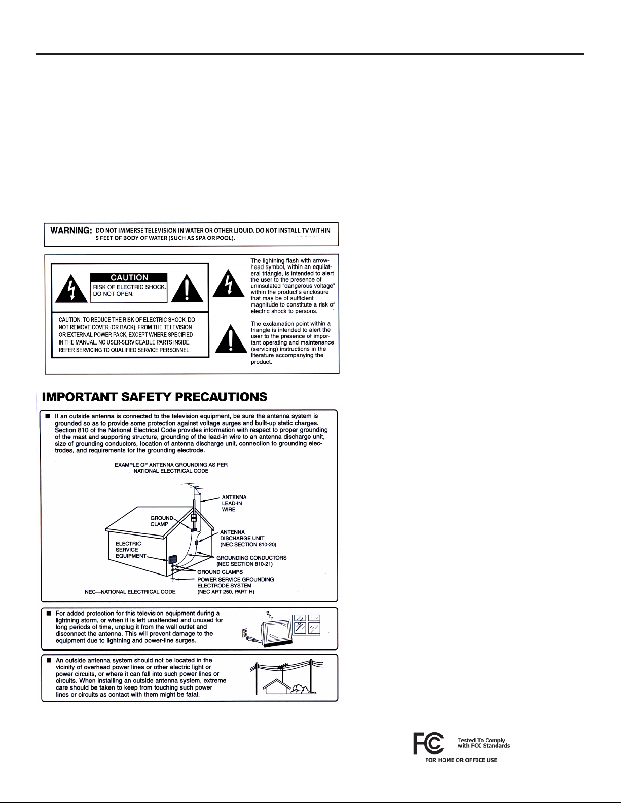
NOTE TO CATV SYSTEM INSTALLER: This reminder is provided to call the CATV system installer’s attention to Article 820-40 of the National
Electrical Code that provides guidelines for proper grounding and, in particular, species that the cable ground shall be connected to the
grounding system of the building, as close to the point of cable entry as practical.
WARNING: To reduce the risk of re or electric shock, do not expose the inside of this apparatus to rain or moisture.
This product utilizes tin-lead solder.. Disposal of these materials may be regulated due to environmental considerations. For
disposal or recycling information, please contact your local authorities or the Electronic Industries Alliance: www.eia.org.
Disclaimer: While SunBriteTV LLC intends to make this manual accurate and complete, we do not make claims that the information
contained within covers all details, conditions or variations, nor does it provide for every possible contingency in connection with the
installation or use of this product. The information contained in this manual may change without notice.
Page 2
All Rights Reserved. 2014 ©SunBriteTV® LLC
Page 3
Important Safety Instructions
Cleaning Instructions: See “Care of SunBriteTV” on page 36.
Attachments: Do not use attachments not specically recommended by the manufacturer. Use of improper attachments can
result in accidents.
Power Source: SunBriteTV must operate on a power source indicated on the specication label. If you are not sure of the type of
power supply used in your home, consult your dealer or local power company. When using the TV outdoors, you must use a GFIprotected AC outlet with “in-use” waterproof cover.
Installation: Do not place the product on an unstable cart, stand, tripod, table, or anywhere the unit is not permanently installed.
Placing the product on an unstable place can cause the product to fall, resulting in potential serious personal injuries, as well as
damage to the product.
Precautions when Transporting the TV: Carrying the television requires at least two people.
FCC Statement
This equipment complies with the limits for
a Class B digital device, pursuant to part 15
of the FCC Rules. These limits are designed to
provide reasonable protection against harmful
interference in a residential installation. This
equipment generates, uses, and can radiate radio
frequency energy and, if not installed and used
in accordance with the instructions, may cause
harmful interference to radio communications.
However, there is no guarantee that interference
will not occur in a particular installation. If this
equipment does cause harmful interference
to radio or television reception, which can be
determined by turning the equipment o and
on, the user is encouraged to try to correct the
interference by one or more of the following
measures:
1. Reorient or relocate the receiving antenna.
2. Increase the separation between the equipment
and receiver.
3. Connect the equipment into an outlet on a
circuit dierent from that to which the receiver is
connected.
4. Consult the dealer or an experienced radio/TV
technician for help.
SunBriteTV Model DS-4720 Operator’s Manual
Modications not expressly approved by the
manufacturer could void the user’s authority
to operate the equipment under FCC rules.
This device complies with part 15 of the FCC
Rules. Operation is subject to the following two
conditions:
1. This device may not cause harmful interference.
2. This device must accept any interference
received, including interference that may cause
undesired operation.
Page 3
Page 4

Important Safety Instructions
Ventilation: Adequate ventilation must be maintained to ensure reliable and continued operation and to protect the
television from overheating. There must be at least 1.5” of space on all sides.
Power cord protection: The power cord must be routed properly to prevent people from stepping on it, or objects
from resting on it. Check the cords at the plugs and product.
Power source: This product must operate on a power source specied on the specication label. If you are unsure of
the type of power supply used in your home, consult your dealer or local power company.
Do not let metal pieces or objects of any kind fall into the television from ventilation holes. High voltage ows in the
product, and inserting an object can cause electric shock and/or short internal parts.
Do not mount SunBriteTV near a motor or transformer where strong magnetism is generated. Images on the
television will become distorted and the color irregular.
Do not mount SunBriteTV near heat sources such as radiators, heaters, stoves and other heat-generating products
(including ampliers).
Do not submerge SunBriteTV in water: The SunBriteTV will resist water exposure from normal rain, sprinklers,
garden hoses, etc.; however, it is not designed to be submerged in water.
Do not pressure-wash SunBriteTV: SunBriteTV will resist water exposure from normal rain, sprinklers, garden hoses,
etc.; However, it is not designed to withstand pressure washers, high-pressure water jets, or hurricane-type weather.
Do not service SunBriteTV yourself: Removal of the television screen cover may expose you to high voltage or other
dangerous risks. Refer all servicing to a qualied service professional. Warranty will not be honored if you service the
unit yourself.
Repair: If any of the following conditions occurs, unplug the power cord, and call a qualied service professional to
perform repairs:
When power cord or plug is damaged.
When objects have fallen into the product.
If unit was submerged in water or pressure-washed.
When product does not operate properly as described in the operating instructions. Do not touch the controls other
than as described in the operating instructions. Improper adjustments of controls not described in the
instructions can cause damage, which can require extensive repair work by a qualied technician.
When the product has been dropped or damaged.
When the product displays an abnormal condition. Any noticeable abnormality in the product indicates that the
product needs servicing.
Replacement parts: In case the product needs replacement parts, make sure that the service person uses
replacement parts provided by SunBriteTV. Use of unauthorized parts can result in re, electric shock and/or other
danger.
Safety checks: Upon completion of service or repair work, ask the service technician to perform safety checks to
ensure that the product is in proper operating condition.
Page 4
Page 5

Table of Contents
Important Safety Instructions
Table of Contents
Supplied Accessories
TV Installation
Choose a Location for the TV
Rear Panel Internal Connect Source
Rear Panel Connection Diagrams
Side Panel and Front Panel Controls
Remote Control Guide
On-Screen Display Controls
Adjusting On-Screen Displays
Channel Menu
Picture Menu
Audio Menu
2
5
6
7
8
9
18
19
21
23
25
26
Time Menu
Setup Menu
Lock Menu
Using the USB Input / Menu
Troubleshooting
Care of SunBriteTV - Filter cleaning
Specications
Features Information and Instructions
Extreme Climate Warning
Programming Other Manufacturers’ Universal Remote Control Devices
SunBriteTV Pixel Quality Policy
Appendix A - RS232 Cable Pinout
Ir Emitter Installation
Appendix B - RS232 Control Codes
27
28
31
34
35
36
37
39
39
39
39
40
40
42
SunBriteTV Model DS-4720 Operator’s Manual
Page 5Page 5
Page 6
Supplied Accessories
Unpacking
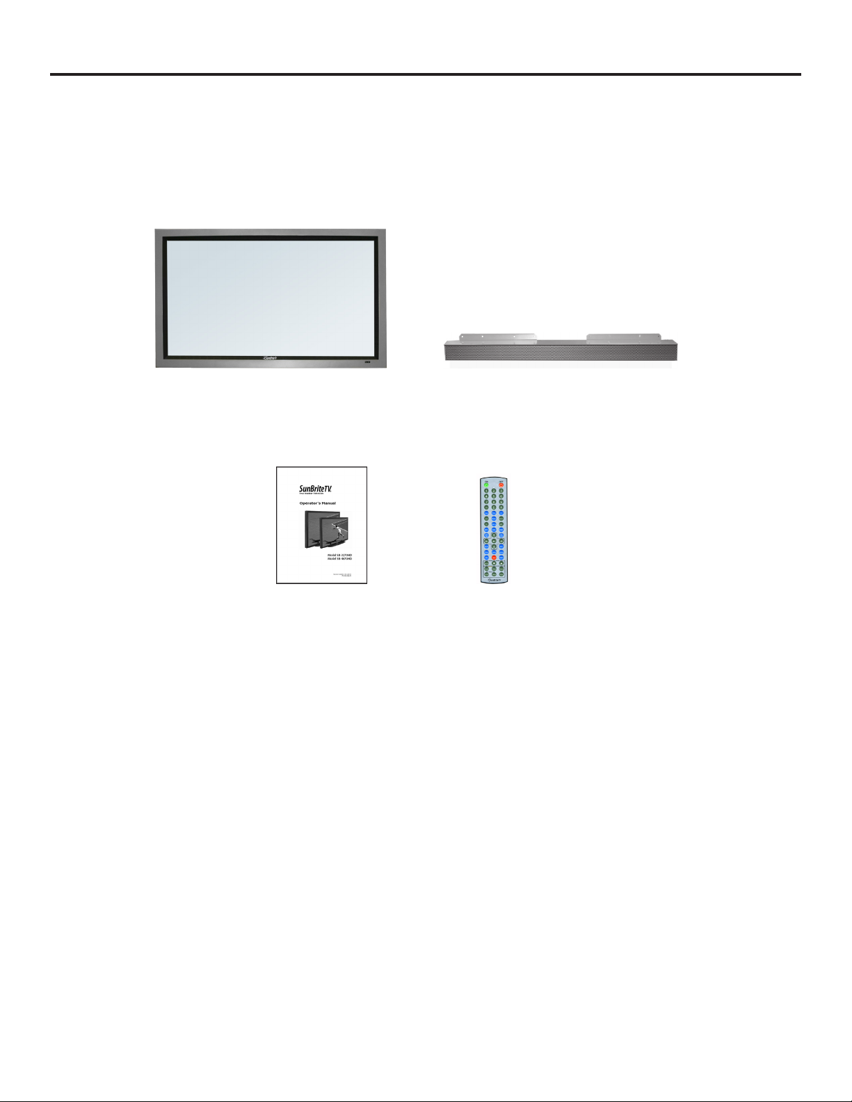
After unpacking the SunBriteTV television, please make sure that the following items are included in the carton and
that they are in good condition. If items are damaged or missing, contact your dealer immediately.
SunBriteDS LCD Display Speaker Module (optional)
Remote Control with Batteries Operator’s Manual
Model 4720
Operator’s Manual Remote Control
Speaker Module (Optional)
Page 6
Page 7
Display Installation - Choose a Location for the Display
Choose a Location for the Display
Important: The display must be installed at
least 5 feet from pool, spa, or other body of
water.
The TV should be installed so the screen is not facing
direct sunlight, or can be easily turned away from
direct sunlight.
Ideal placement is in an area where the TV is shaded
by trees, landscape and/or structures, or under a patio
cover or gazebo.
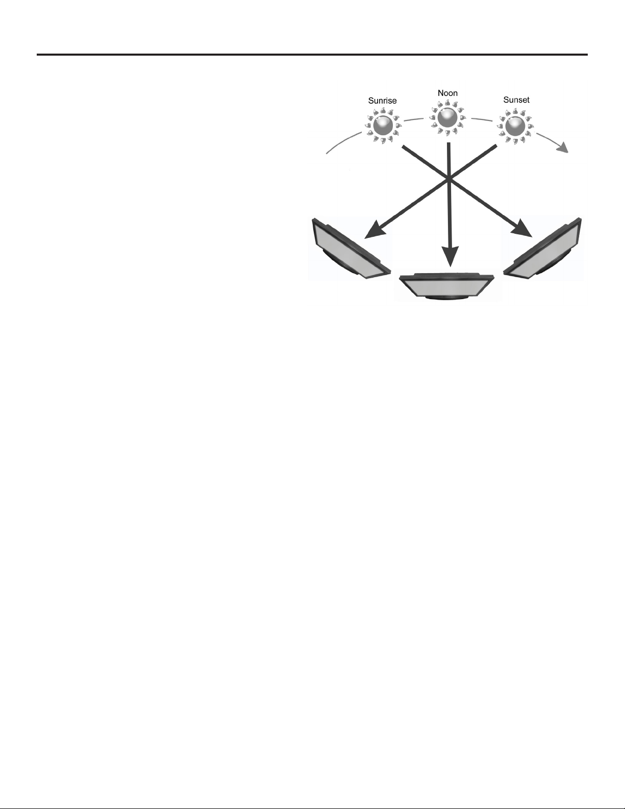
Remember that the position of the sun changes during
the day, as seen in the drawing at right., This means
that the quality of the picture will change during the
day. If you intend to install the TV in areas where direct
sunlight will reach it, it’s best to postion the TV for
optimum performance during the time of day when
you do most of your TV watching.
If the sun shines directly on the screen for long periods
of time, dark areas may develop on the screen. This is a
normal reaction for the LCD panel, and will not cause
damage to the screen. Either turn the screen away from
the sun, or apply shade to the TV, and the dark areas
will quickly disappear.
SunBriteTV Model DS-4720 Operator’s Manual
Page 7
Page 8
TV Installation – Rear Panel Internal Connect Source
WARNING: Do not connect the power source before making connections.
Internal Connect Source
The Internal Connect Source allows you to easily connect to the Audio, Video, S-Video, SVGA, HDMI, Audio Out, and RF connectors.
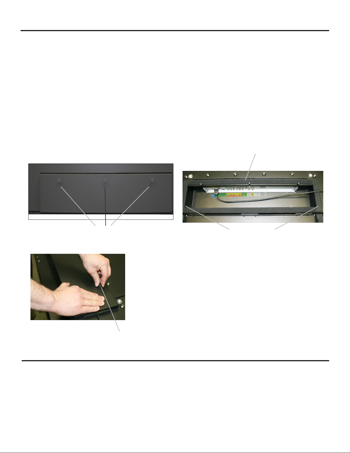
The Internal Connect Source is inside the Cable Cover located on the back of the unit (Figure1).
1. Unscrew the two Thumb Screws (Figure1), and pull the cover towards you.
2. Route the cables to the proper inputs, and place the cable cords over the Rubber Sealing Gasket (Figure 2).
Note: There is an indentation on the Rubber Sealing Gasket on the bottom portion of the right and left sides.) Make sure cable
cords are not placed on the indentation.
3. Close the cover.
4. Press rmly on the cover, and screw the Thumb Screws tightly (Figure3).
Figure 1 Figure 2
Thumb Screws
Figure 3
Rubber Sealing Gasket
Cables are not to be placed
over the indentations
Thumb Screw
TV Installation - Connecting the Power Cord
Do not connect power cord until all cable connections have been made.
Connect the power cord to a GFCI protected AC outlet with an “in-use” waterproof cover.
WARNING:
TV AND GFCI RECEPTACLE MUST BE INSTALLED AT LEAST 5 FEET AWAY FROM STANDING WATER , SUCH AS (BUT NOT LIMITED
TO) A POOL OR SPA. BE SURE TO CHECK LOCAL ELECTRICAL CODES AND COMPLY WITH THEIR LOCAL STANDARDS.
Page 8
Page 9
TV Installation – Rear Panel Connections
Connections
3
1
4 53 7
6
9 10 11
13
2
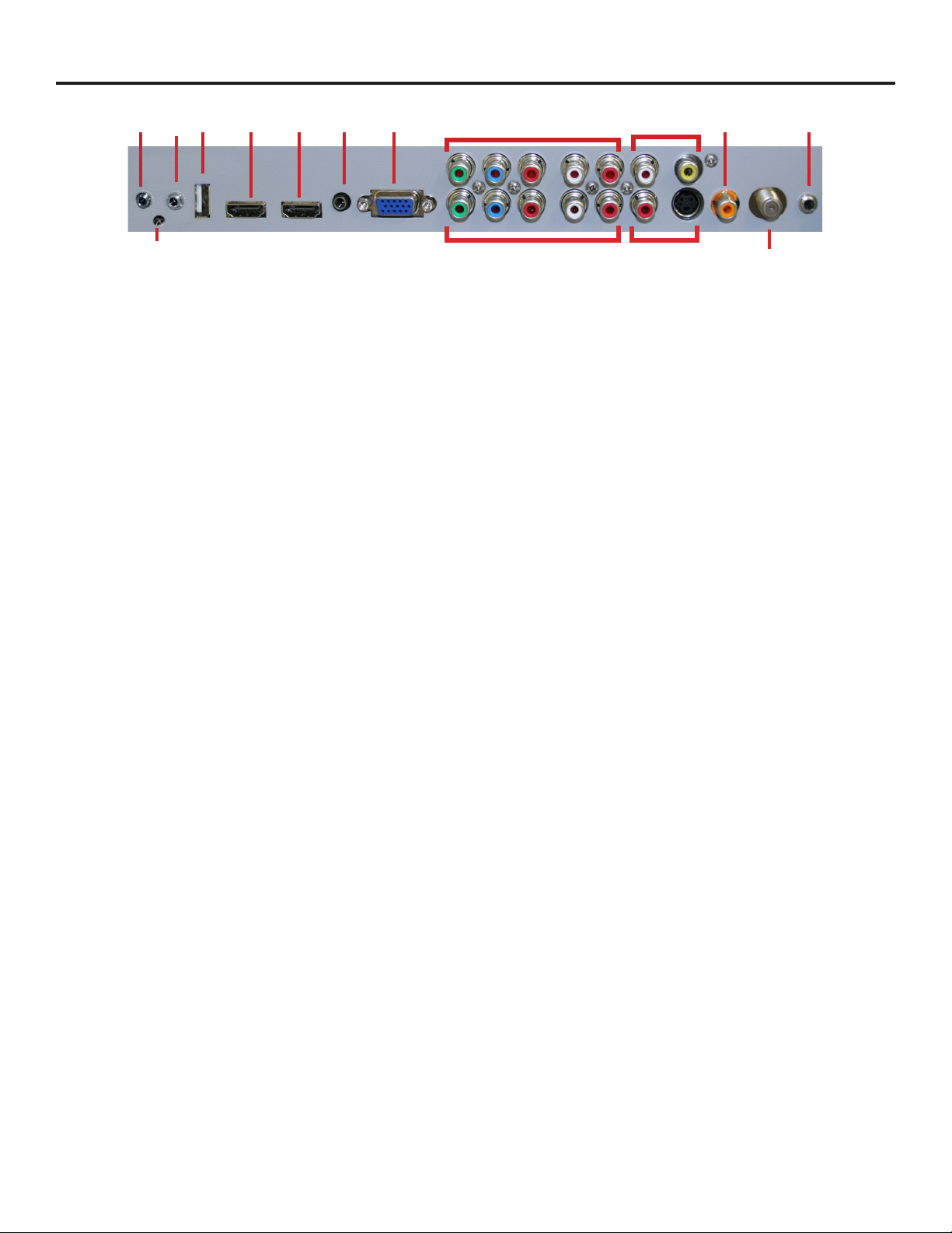
1. RS232 - For remote control using RS232 commands
2. IR WINDOW - For remote control using IR commands.
3. SERVICE PORT - These ports are for factory service only...DO NOT USE
4. HDMI 1 - Connects to devices that use HDMI cables such as Blu-ray or HD DVD player or HD cable / satellite set-top box. This
connection port receives pure digital audio and high denition signal through one single cable. This port also can accept a
HDCP video device for video or PC for monitor display usage. Use the SOURCE button to select HDMI1 on your MAIN SOURCE
to view this connection. Please note: when using HDMI, your sound signal must be PCM for the TV to decode digital audio.
When using this source for PC display, you must connect the audio cable to VGA Stereo Input for audio.
5. HDMI 2 - Same as HDMI 1
6. VGA STEREO INPUT - This connection port is for people who want to provide audio to the TV when using a PC or a DVI video
device. Use a 3.5mm mini-jack audio cable (headphone jack) to provide audio for a HDCP enabled DVI video device or PCs
with VGA or DVI connection.
7. VGA - This connection port connects to a PC for video using VGA cable. Be sure to connect your audio cable to the VGA Stereo
input if you want sound out of the VGA video source. Use the SOURCE button to select VGA on your MAIN SOURCE to view
this connection.
8. COMPONENT 1 (Lower) - This connection ports are for DVD players or satellite/cable set-top boxes that use component
cables. From left to right, connect green, blue and red for video, and then connect white for left channel audio, red for right
channel audio. Use the Source Button to select YPbPr1 to review this connection.
8
10
12
9. COMPONENT 2 (Upper) - his connection ports are for DVD players or satellite/cable set-top boxes that use component
cables. From left to right, connect green, blue and red for video, and then connect white for left channel audio, red for right
channel audio. Use the Source Button to select YPbPr2 to review this connection.
10. AV 1 (CVBS or S-Video) - Connects to devices that use composite or s-video cables such as VCR or camcorder or video game
consoles. Connect the video portion with either the yellow connector or the S-Video connector. Do NOT connect both video
connectors. Use the SOURCE button to select AV1 (CVBS) on your MAIN SOURCE if you are using the yellow plug for video,
use the SOURCE button to select AV1 (S-Video on your MAIN SOURCE if you are using the S-Video connector to view this
connection.
11. DIGITAL AUDIO OUT - This connection port is used for sending out audio signals to other audio devices such as stereo/
surround sound receivers. The orange (SPDIF OUT) connector sends out either bit-stream or PCM digital sound signal to a
home theater receiver with digital input.
12. ATSC/NTSC/QAM – This connection is for digital or analog cable without the cable box or over-the-airwave antennas. The
tuner is a hybrid tuner that tunes to both analog and digital channels. This connection uses coaxial RF cable. For over- the
airwave digital stations please check http://www.antennaweb.org.
13. ANALOG AUDIO OUT (Variable) - Used to connect headphones, stereo receivers and amplied speakers via a 3.5mm
headphone jack.
SunBriteTV Model DS-4720 Operator’s Manual
Page 9
Page 10
TV Installation – Rear Panel Connections
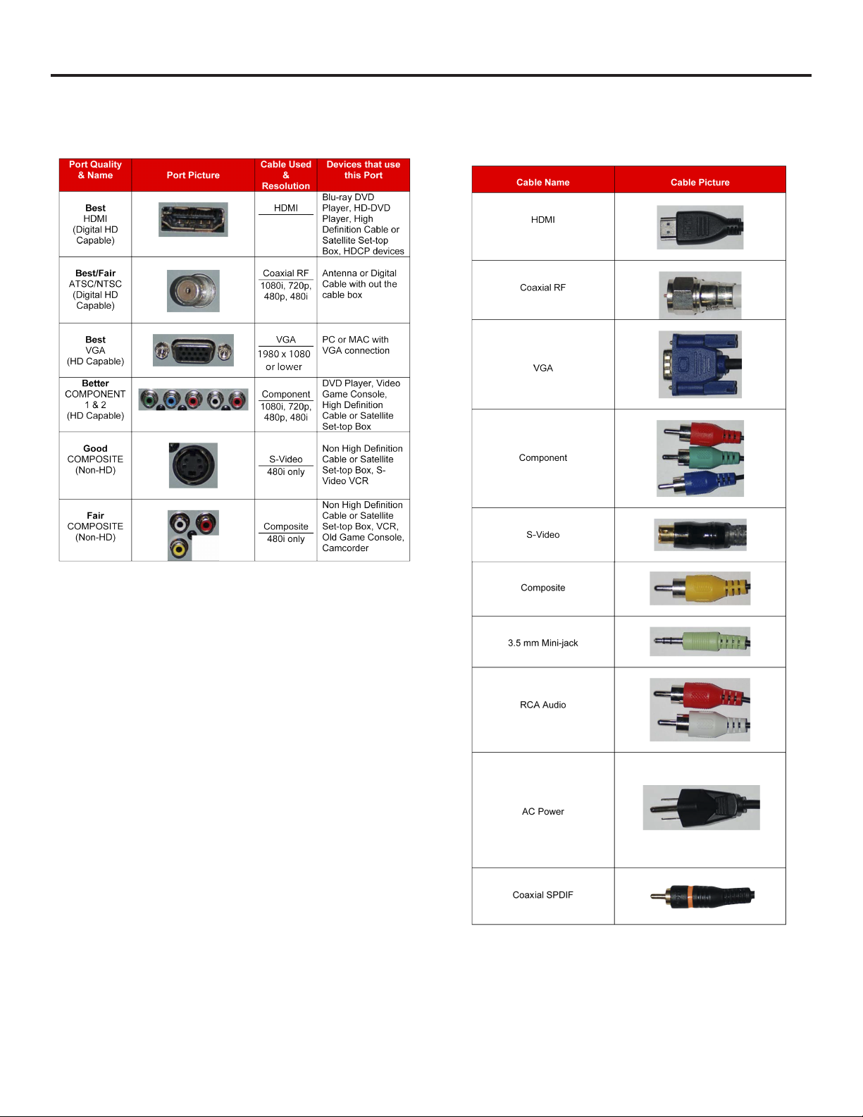
Connection Descriptions:
Cable Descriptions:
1080p, 1080i
720p, 480p
480i
Red
Green
Blue
Yellow
Green
Red
White
Page 10
Page 11
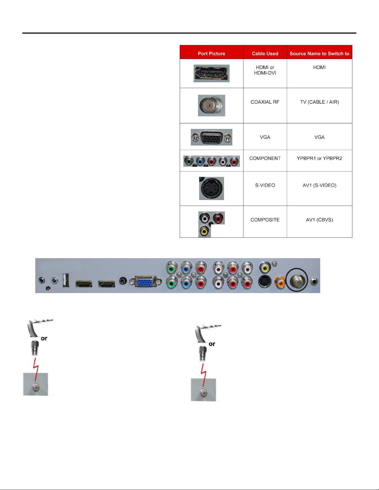
TV Installation – Rear Panel Connections
Switching Sources for Ports:
Your SunBrite TV oers several options when connecting
your devices to the TV. The chart below will help you
understand which source you switch to for each of the
ports.
CONNECTING TO AN ANTENNA
Connecting to Digital Cable without Cable Box or Antenna
1. Make sure the power to the TV is turned o.
2. Connect the Coaxial RF cable from your
antenna or digital cable to the ATSC/NTSC port o
the back of the TV.
3. Turn on the TV.
4. Select TV (Air) for antenna or TV (Cable) for
digital cable from either your remote control’s
source button or source button on the right side
of the TV.
5. Use the On-Screen Display to scan for channels.
Please Note :
1. Not all broadcasts are in High Denition (HD). Please refer to your local broadcasting stations for more information.
2. The TV’s tuner is designed for HDTV therefore requires a stronger signal than normal TVs. If you cannot achieve that
signal level with your antenna or cable, the TV might lose picture or sound.
Connecting to Cable or Antenna
1. Make sure the power of the TV is turned o.
2. Connect the Coaxial RF cable from your
antenna or cable to the
ATSC/NTSC port o the back of the TV.
3. Turn on the TV.
4. Select TV (Air) for antenna or TV (Cable) for
cable from either your remote control’s source
button or source button on the right side of the
TV.
5. Use the On Screen Display to scan for channels.
SunBriteTV Model DS-4720 Operator’s Manual
Page 11
Page 12
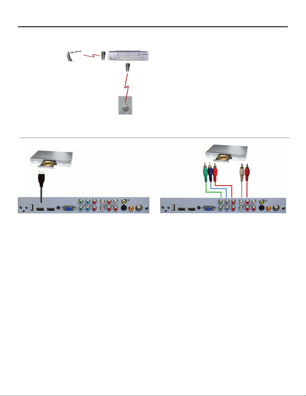
TV Installation – Rear Panel Connection Diagrams
CONNECTING TO AN ANTENNA--(Continued)
Connecting to Cable or Antenna through VCR
1. Make sure the power of the TV is turned o.
2. Make sure there is an antenna or cable
connection to the VCR already.
3. Use a Coaxial RF cable and connect from your
VCR’s Antenna Out or Output to TV to the ATSC/
NTSC port of your TV.
4. Turn on the TV.
5. Select TV (Air) for antenna or TV (Cable) for
digital cable from either your remote control’s
source button or source button on the TV.
6. Use the On-Screen Display to scan for channels.
CONNECTING TO A DVD PLAYER
Connecting with HDMI (Best)
Please Note :
1. Some VCRs must be turned On before its output will have
a signal to the TV. Please consult your VCR manual for further
reference.
2. Not all broadcasts are in High Denition (HD). Please refer to
your local broadcasting stations for more information.
3. This model’s tuner is designed for HDTV therefore it requires a
stronger signal than normal TVs. If you cannot achieve that signal
level with your antenna or cable, the TV might lose picture or
sound.
4. This TV will turn o automatically if there’s no signal present
for more than 15 minutes.
Connecting with
Component
(Better)
1. Make sure the power of the TV and your DVD player is
turned o.
2. Connect a HDMI cable to the HDMI port of your DVD
player and the other end to the HDMI port o the back of
your TV.
3. Turn on the TV and your DVD player.
4. Use the remote control’s source button or the source
button on the TV to switch to HDMI.
Please Note :
1. Refer to the DVD player’s manual to make sure the DVD
player is congured to output correctly to the TV.
2. This TV does not decode Bit stream digital audio, so make
sure the DVD is setup for PCM digital audio through
HDMI.
3. If HDMI 1 is occupied, use HDMI 2 as your connection
port.
1. Make sure the power of TV and your DVD player is turned o.
2. With a Component Cable, connect the green connector to the
DVD player and Component 1’s green connector port on the TV.
3. Connect the blue color connector to your DVD player and
Component 1’s blue connector port on the TV.
4. Connect the red color connector to both your DVD player and
Component 1’s red connector port on the TV.
5. With an RCA Audio Cable, connect the white color connector to
both your DVD player and Component 1’s white connector port
on the TV.
6. Connect the red color connector to both your DVD player and
7. Component 1’s red connector port on the TV.
8. Turn on the TV and your DVD player. Use the remote control’s
source button or the source button on the TV to switch to YPbPr1.
Please Note :
1. If Component 1 is already occupied, please use Component 2 as
your connection port and switch to source YPbPr2.
2. Refer to the DVD player’s manual to make sure the DVD player is
congured to output correctly to the TV.
3. This TV will turn o automatically if there’s no signal present for
more than 15 minutes.
Page 12
Page 13
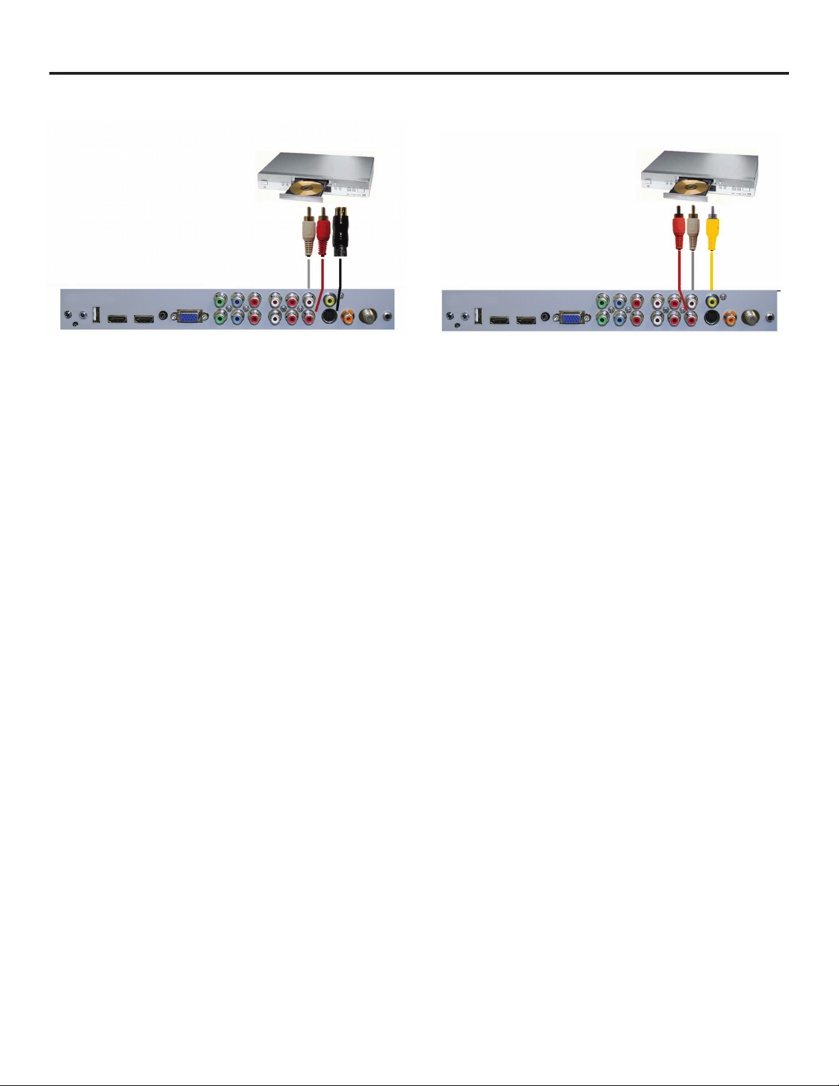
TV Installation – Rear Panel Connection Diagrams
CONNECTING TO A DVD PLAYER (Continued)
Connecting with S-Video (fair)
1. Make sure the power of the TV and your DVD player is
turned o.
2. Obtain an S-Video Cable. Connect the S-Video connector to
both your DVD player and Composite’s S-Video connector
port o the back of your TV.
3. Obtain a RCA Audio Cable. Connect the white color
connector to both your DVD player and Composite’s white
connector port o the back of your TV.
4. Connect the red color connector to both your DVD player
and Composite’s red connector port o the back of your TV.
5. Turn on the TV and your DVD player.
6. Use the remote control’s source button or the source button
on the right side of the TV to switch to AV1 (S-Video).
Connecting with
Composite (Fair)
1. Make sure the power of the TV and your DVD player is
turned o.
2. Obtain a Yellow Video Cable. Connect the Yellow Video
connector to both your DVD player and Composite’s Yellow
Video connector port o the back of your TV.
3. Obtain a RCA Audio Cable. Connect the white color
connector to both your DVD player and Composite’s white
connector port o the back of your TV.
4. Connect the red color connector to both your DVD player
and Composite’s red connector port o the back of your TV.
5. Turn on the TV and your DVD player.
6. Use the remote control’s source button or the source
button on the right side of the TV to switch to AV1 (CVBS).
Please note:
1. If AV 1 is already occupied, use AV2, as your connection port, and switch source to AV 2 (S-Video)
2. Reference the DVD player’s manual to make sure the DVD player is congured to output correctly to the TV.
3. This TV will turn o automatically if there’s no signal present for more than 15 minutes.
SunBriteTV Model DS-4720 Operator’s Manual
Page 13
Page 14
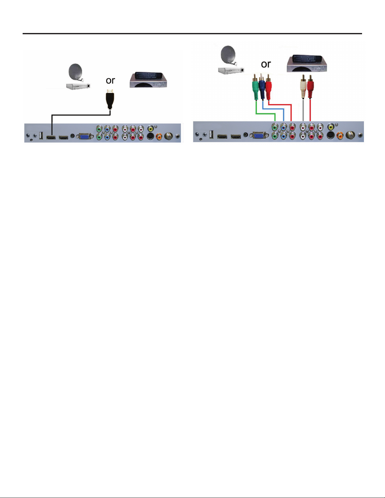
TV Installation – Rear Panel Connection Diagrams
CONNECTING TO A SATELLITE OR CABLE SET-TOP BOX
Connecting with HDMI (Best)
1. Make sure the power of the TV and your set-top box is
turned o.
2. Connect a HDMI cable to the HDMI output of your set-top
box and the other end to the HDMI port o the back of
your TV.
3. Turn on the TV and your set-top box.
4. Use the remote control’s source button or the source
button on the right side of the TV to switch to HDMI 1.
Please Note :
1. Refer to the set-top box’s manual, to make sure the settop box is congured to output correctly to the TV.
2. If HDMI 1 is already occupied, use HDMI 1 as your
connection port and switch source to HDMI 2.
3. This model supports SONY’s universal remote code. If
SunBriteTV is not listed, please look up SONY’s codes in
your universal remote’s hand book.
4. This TV will turn o automatically if there’s no signal
present for more than 15 minutes.
Connecting with
Component (Better)
1. Make sure the power of TV and your set-top box is turned o.
2. Obtain a Component Cable. Connect the green color
connector to both your set-top box and Component 1’s green
connector port o the back of your TV.
3. Connect the blue color connector to both your set-top box and
Component 1’s blue connector port o the back of your TV.
4. Connect the red color connector to both your set-top box and
Component 1’s red connector port o the back of your TV.
5. Obtain a RCA Audio Cable. Connect the white color connector
to both your set-top box and Component 1’s white connector
port o the back of your TV to the right side of your green,
blue, red component connection.
6. Connect the red color connector to both your set-top box and
Component 1’s red connector port o the back of your TV to
the right side of your green, blue, red component connection.
7. Turn on the TV and your set-top box.
8. Use the remote control’s source button or the source button
on the TV to switch to YPbPr1.
Please Note :
1. If Component 1 is already occupied, please use Component 2
is your connection port and switch to source YPbPr2.
2. Please refer to the set-top box’s manual to make sure the settop box is congured to output correctly to the TV.
3. This model supports SONY’s universal remote code. If
SunBriteTV is not listed, please look up SONY’s codes in your
universal remote’s hand book.
4. This TV will turn o automatically if there’s no signal present
for more than 15 minutes.
Page 14
Page 15
TV Installation – Rear Panel Connection Diagrams
CONNECTING TO A SATELLITE OR CABLE SET-TOP BOX (Continued)
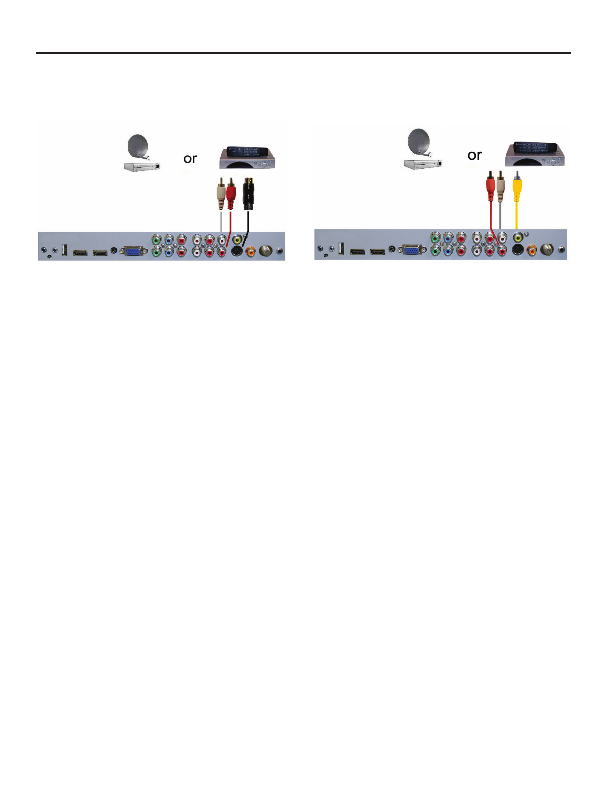
Connecting with S-Video (Fair)
1. Make sure the power of the TV and your DVD player is
turned o.
2. Obtain an S-Video Cable. Connect the S-Video connector
to both your DVD player and Composite’s S-Video
connector port o the back of your TV.
3. Obtain a RCA Audio Cable. Connect the white color
connector to both your DVD player and Composite’s
white connector port o the back of your TV.
4. Connect the red color connector to both your DVD player
and Composite’s red connector port o the back of your
TV.
5. Turn on the TV and your DVD player.
6. Use the remote control’s source button or the source
button on the right side of the TV to switch to AV1
(S-Video).
Please Note :
1. If AV 1 is already occupied, use AV 2 as your connection
port and switch source to AV 2 (S-Video).
2. Refer to the set-top box’s manual to make sure the set-top
box is congured to output correctly to the TV.
3. This model supports SONY’s universal remote code. If
SunBriteTV is not listed, please look up SONY’s codes in
your universal remote’s hand book.
4. This TV will turn o automatically if there’s no signal
present for more than 15 minutes.
Connecting with
Composite (Fair)
1. Make sure the power of the TV and your DVD player is
turned o.
2. Obtain a Yellow Video Cable. Connect the Yellow Video
connector to both your DVD player and Composite’s Yellow
Video connector port o the back of your TV.
3. Connect the white color connector to both your DVD player
and Composite’s white connector port o the back of your
TV.
4. Connect the red color connector to both your DVD player
and Composite’s red connector port o the back of your TV.
5. Turn on the TV and your DVD player.
6. Use the remote control’s source button or the source button
on the right side of the TV to switch to AV1 (CVBS).
Please Note :
1. If AV 1 is already occupied, use AV 2 as your connection port
and switch source to AV 2 (S-Video).
2. Refer to the set-top box’s manual to make sure the set-top
box is congured to output correctly to the TV.
3. This model supports SONY’s universal remote code. If
SunBriteTV is not listed, please look up SONY’s codes in your
universal remote’s hand book.
4. This TV will turn o automatically if there’s no signal present
for more than 15 minutes.
SunBriteTV Model DS-4720 Operator’s Manual
Page 15
Page 16
TV Installation – Rear Panel Connection Diagrams
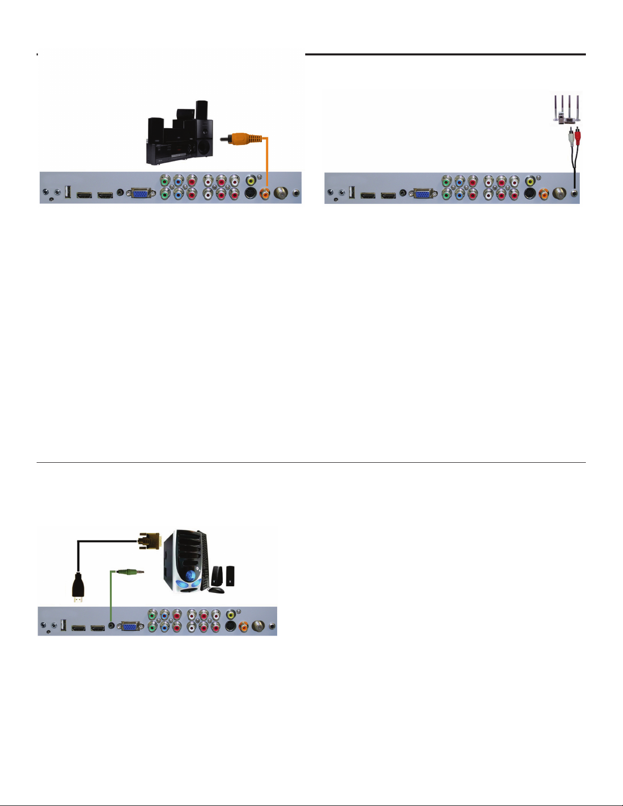
CONNECTING TO AN EXTERNAL AMPLIFIER OR AMPLIFIED SPEAKERS
Connecting with Coaxial SPDIF Digital (Best)
Connecting with RCA Audio Analog (Good)
1. Make sure the power of the TV and your receiver is turned o.
2. Obtain a Coaxial SPDIF cable, connect it to your receiver’s
coaxial SPDIF digital input and the Coaxial SPDIF connection
on the LINE OUT port o the back of the TV.
3. Turn on the TV and your receiver.
Please Note :
1. If you want pure digital stream for your receiver to decode,
you must also congure the TV’s OSD Sound->Digital Audio
Out function. Make sure the option is on Bit Stream.
2. If your receiver is making static noises when receiving Bit
Stream, you must use the PCM option instead.
3. Refer to the receiver’s manual to make sure the receiver is
congured to receive signals correctly from the TV
CONNECTING TO A PC
Connecting with DVI Digital (Best)
1. Make sure the power of the TV and your receiver is turned
o.
2. Obtain a 3.5mm stereo/audio cable (if your amplier
audio connection requires RCA audio out jacks you
will need to obtain an 1/8” Stereo Mini Plug to RCA
adapter cable). Connect it to your receiver’s audio input
connection and the 3.5mm stereo/audio connection on
the Analog Audio port on the back of the TV.
3. Turn on the TV and your receiver.
Please Note :
1. If you want pure digital stream for your receiver to
decode, you must also congure the TV’s OSD Sound>Digital Audio Out function. Make sure the option is on
Bit Stream.
2. If your receiver is making static noises when receiving Bit
3. Stream, you must use the PCM option instead.
4. Refer to the receiver’s manual to make sure the receiver
is congured to receive signals correctly from the TV
1. Make sure the power of the TV and your receiver is turned o.
2. Obtain a HDMI to DVI conversion cable; connect the DVI side
of the conversion cable to the DVI output of your PC, and the
HDMI side of the conversion cable to the HDMI port o the
back of TV.
3. Obtain a 3.5 mm Mini-jack, connect to the audio out of your PC
and the other end to the VGA Stereo Input Port.
4. Turn on the power to the TV and the PC.
5. From the remote control’s source button, or the Source button
from the TVs panel, switch to HDMI.
Please Note :
1. For the best picture, set your PC resolution to 1920 x 1080
at 60 Hz. Refer to the PC or graphic card manual for further
instructions on how to set your resolution and refresh rate.
2. Refer to your PC manual for video output requirements of the
video card.
3. The TV will turn o automatically if there’s no signal present for
more than 15 minutes.
4. If HDMI 1 is already occupied, use HDMI 2 as your connection
port, and switch source to HDMI 2.
Continued on next page
Page 16
Page 17
TV Installation – Rear Panel Connection Diagrams
CONNECTING TO A PC (Continued)
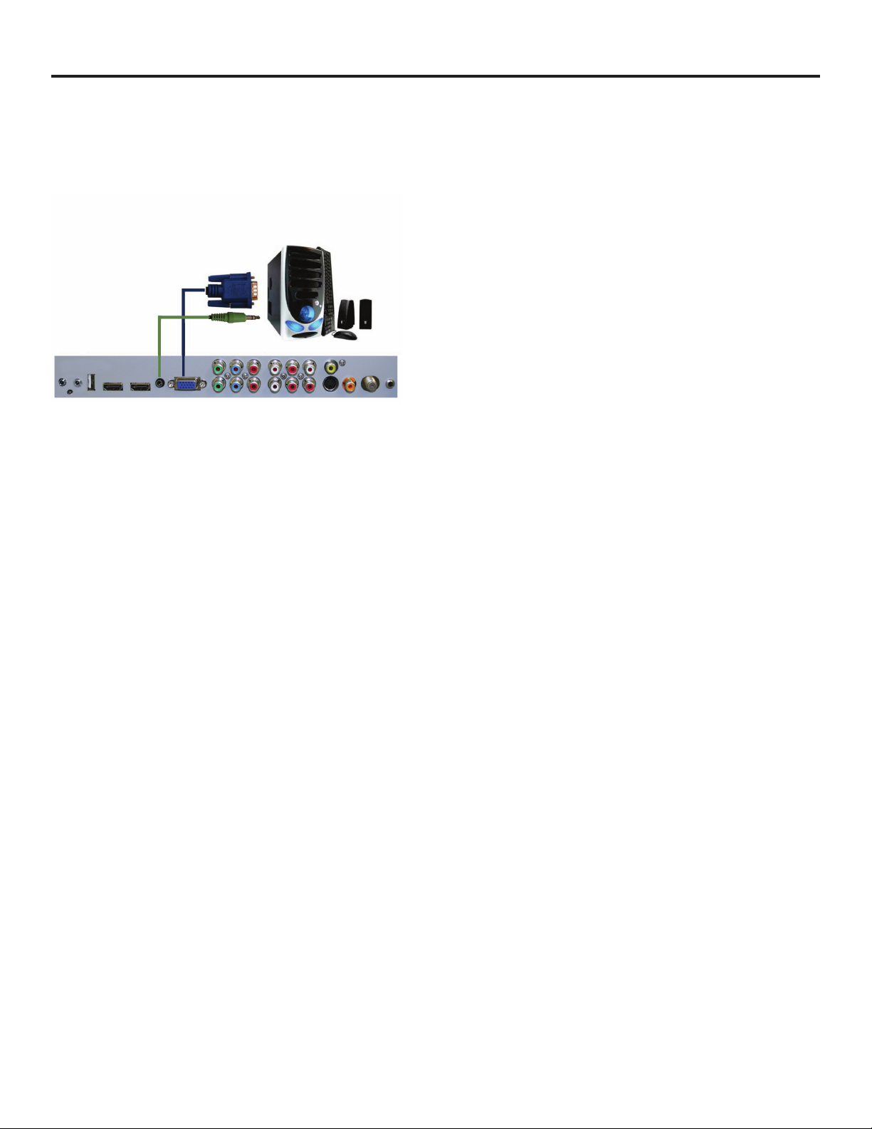
Connecting with VGA Analog (Good)
1. Make sure the power of the TV and your PC is turned o.
2. Obtain a 15-pin D-Sub VGA cable, connect to the VGA output of
your PC and the other end to the VGA port o the back of your
TV.
3. Obtain a 3.5 mm Mini-jack, connect to the audio out of your PC
and the other end to the VGA Stereo Input port.
4. Turn on the power of the TV and your PC.
5. Use the remote control’s source button or the source button the
TV to switch to VGA.
Please Note :
1. For the best results, please set your PC resolution to
2. 1920 x 1080at 60 Hz. Refer to the PC or graphic card’s manual
for further instructions on how to set your resolution and refresh
rate.
3. Refer to your PC manual for video output requirements of the
video card.
4. The VGA port of the TV features a power saving mode which will
automatically turn o the TV if there is no signal provided for
more than 15 minutes.
SunBriteTV Model DS-4720 Operator’s Manual
Page 17
Page 18
TV Installation - Connecting the Power Cord
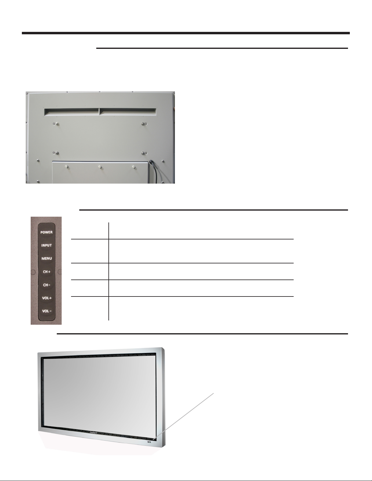
Connecting the Power Cord
WARNING:
TV AND GFCI RECEPTACLE MUST BE INSTALLED AT LEAST 5 FEET AWAY FROM STANDING WATER, SUCH AS (BUT NOT LIMITED
TO) A POOL OR SPA.
Connect the power cord after you have made connections to your video equipment.
Connect the power cord to a GFCI-protected AC outlet
with “in-use” waterproof cover.
Warning: TV must be installed at least 5 feet away from
standing water, such as (but not limited to) a pool or
spa.
Side Panel Controls
Front Panel
Power Turn on the TV by pressing the button once. Press the button again to
turn o the TV.
Input This button switches between the dierent sources of the TV. When the
On-Screen Display (OSD) is active, this button acts as the enter button
and conrms the menu selection.
Menu This button activates the OSD. If a sub-menu is active, pressing this
button will return selection to the previous menu level.
CH+/CH- These buttons change the TV channel up or down. If the OSD is active,
these buttons function as up or down controls for the menu.
Vol+ /Vol- These buttons increase or decrease the volume. If a sub-menu is active,
pressing these buttons will move the selection left or right. If the OSD is
active, Vol+/Vol- is used to select the highlighted options.
IR Sensor
LED power indicator
Ambient light sensor
Page 18
Page 19
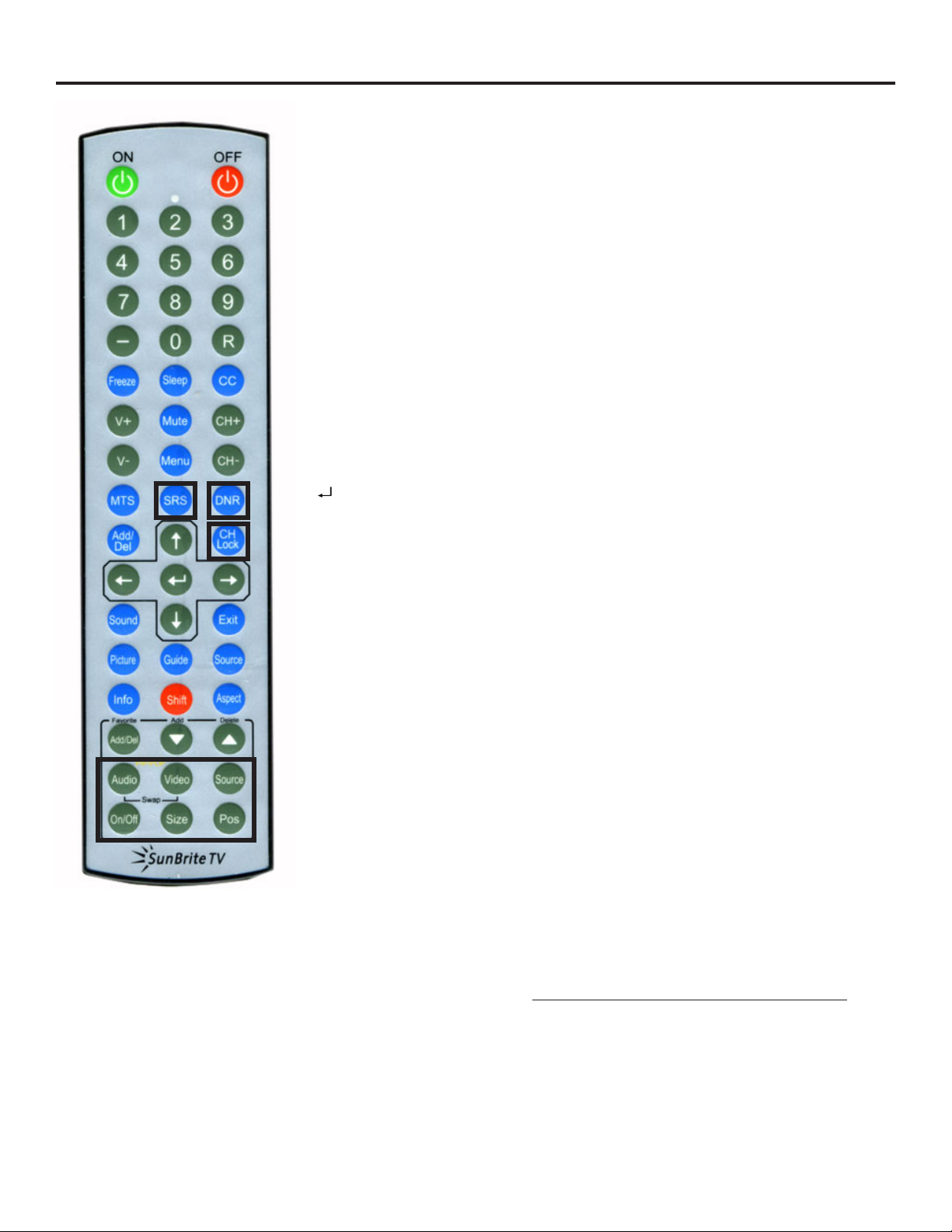
Remote Control Guide
When programming a DirectTV, local cable universal remote control or Control system, you may nd that SunBriteTV may not be on the
list of TV manufacturers. If that is the case, your SunBriteTV supports SONY’s TV universal remote code.
ON – Powers the TV On.
OFF – Powers the TV O.
0~9 – Allows you to set the channels directly. To access a digital channel, use these
buttons with the (-) button to switch channels.
Dash (-) – Insert the dash for selecting digital channels directly.
R – Returns to the previous channel.
FREEZE – Freezes the TV picture. Press the button again to unfreeze the picture.
SLEEP– Sets time for the TV to turn O.
CC– Selects Closed Caption (CC only works under sources TV, AV1 and AV2.)
V+ – Functions the Volume Up.
V- – Functions the Volume Down.
MUTE – Mutes the TVs Audio.
MENU – Opens / Exits the TV menu.
CH+ – Functions the Channel Up.
CH- – Functions the Channel Down.
MTS – Selects stereo, mono, or second audio programming.
h / i / f / g / – Allow you to navigate inside the OSD menu. They also function
as CH+/- and Vol +/-.
– Allows you to select functions inside the OSD menu, acts as the Enter button
for OSD menu for changing channels.
SOUND – Selects various preset sound settings.
EXIT – Exits the TV menu.
PICTURE – Selects various preset picture settings.
GUIDE –Opens the current digital channel information guide.
SOURCE – Cycles between dierent input sources of the TV.
INFO – Shows current channel information, display input and resolution.
SHIFT – Used with the 0-9 numeric pad to select inputs
ASPECT – Selects dierent screen sizes
FAVORITE – Cycles the favorite channels.
FAVORITE ADD / DEL – Adds or deletes the current channel from the favorites
channel list.
The following functions (illustrated with bold squares on the remote) are not
applicable to this TV:
SRS
DNR
ADD/Del
CH Lock
The Picture In Picture/Picture On Picture functions Audio, Video, Source,
On/O, Size and Pos
About the Water-Resistant Remote Control
The SunBriteTV Water-Resistant Remote Controller is engineered to give you many years of service.
“Water-resistant” means that the remote control can be in water for short periods of time without damaging the internal workings of the unit. It
can be left in the rain, and even dropped in water, as long as it is retrieved quickly. The remote control should not be left oating in water.
The functionality of the remote control is under warranty for one year. If the remote control malfunctions within the one-year warranty period,
replace the batteries with new long-life alkaline batteries.
If the problem is not solved with new batteries, contact the SunBriteTV Customer Care Center. SunBriteTV will repair or replace the remote
control at SunBriteTV’s option.
If you have a warranty claim, contact the SunBriteTV Customer Care Center for further instructions.
800.331.4626
www.sunbritetv.com
SunBriteTV Model DS-4720 Operator’s Manual
Page 19
Page 20
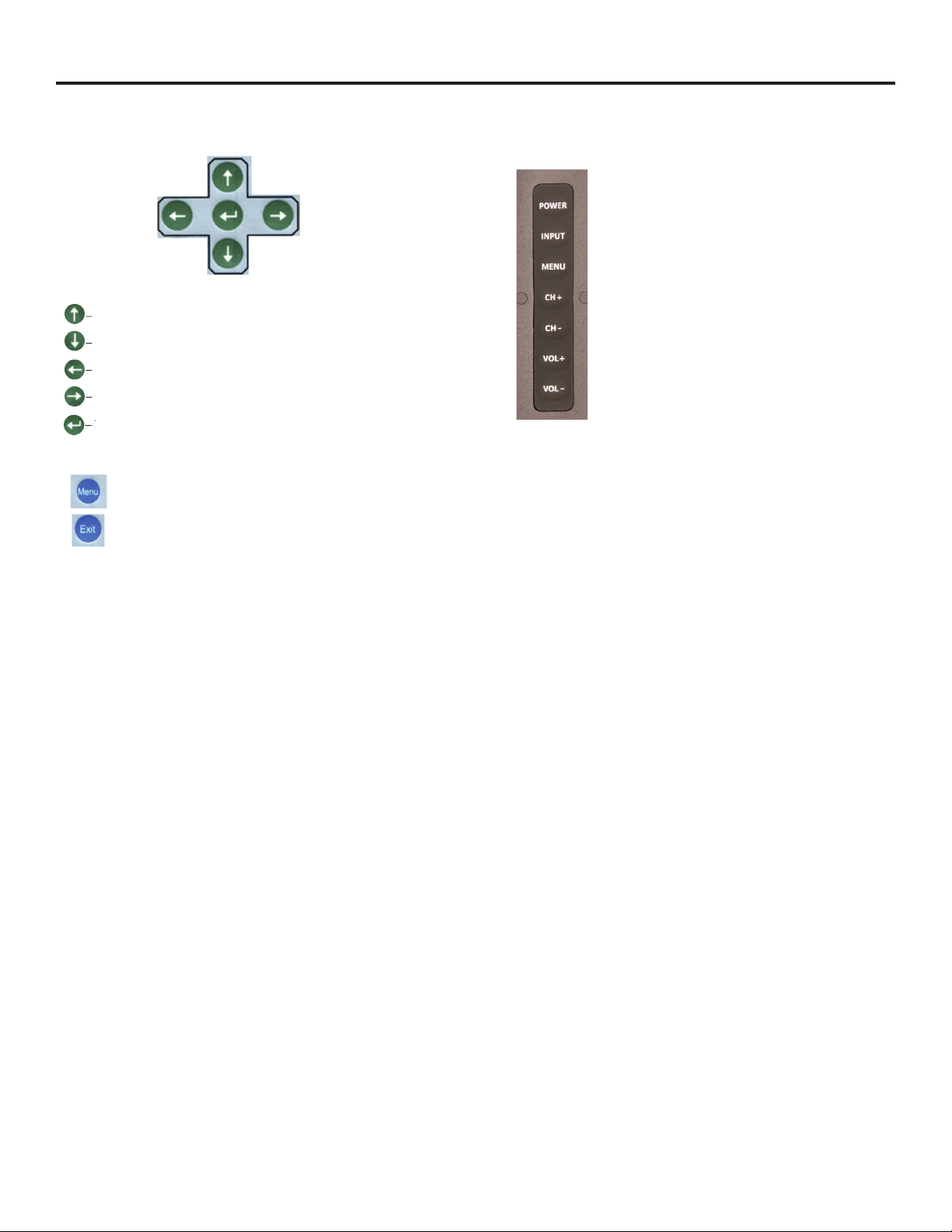
On-Screen Display Functions
Via the Remote Control
Adjusting the On Screen Display (OSD) from the Remote
Control
This button is the UP direction in the OSD.
This buttion functions as the DOWN direction in the OSD.
This button functions as the left direction in the OSD.
This button functions as the right direction in the OSD
This button changes the channel inconjuction with the
number pad and also functions as enter for selectiong
options in the OSD.
This button opens the OSD and also exits the OSD by
going to the previous level of the OSD.
This button exits the OSD entirely.
Via the TV Side Panel Buttons
Adjusting the On Screen Display from the TV Side Panel
Buttons
Menu - This button opens the OSD
CH + p - This button changes the channel to a
higher number and also functions the up direction
of OSD buttons to move the cursor to the item to be
selected.
CH - q- This button changes the channel to a lower
number and also functions as down direction in the
OSD
Vol(+) u - This button increases the volume and
functions as left direction in the OSD. If the OSD is
active, use Vol+ and Vol- to select a choice.
Vol(-) t - This button decreases the volume and
functions as right direction in the OSD. If the OSD is
active, use Vol+/Vol- to select a choice.
Page 20
Page 21
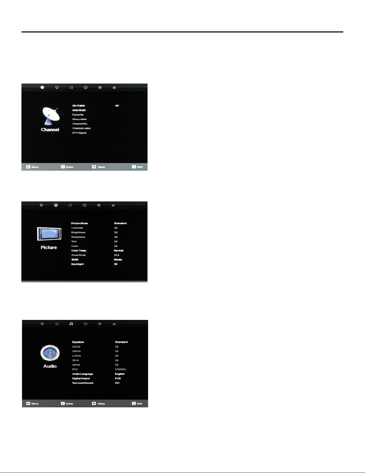
On-Screen Display Menu
Your TV has been factory-set to plug-in and enjoy your programming. In the event you turn on the TV and get the message,
“Please run Channel Auto Scan,” press your remote’s Menu button, press the Channel function and press Auto Scan.
Note: To run the Channel function, you must be in the TV Source. To access the TV source, click Input on the TV’s side panel or
Source button on the Remote Control. Press TV from the Input Select option.
Channel Menu
This menu manages Channel functions including:
Air/Cable Channel Label
Auto Scan DTV Signal strength
Favorite channel
Show/Hide
Channel Number
Picture Menu
This menu manages Picture functions including:
Picture Mode Color Temperature
Contrast Zoom Mode
Brightness 3D Noise Reduction
Sharpness Backlight Level
Tint Dynamic Light Control (page 2)
Color
Audio Menu
This menu manages Audio functions including:
Equalizer mode
Equalizer frequencies
MTS Stereo mode
Audio Language
Digital Output type
Surround Sound
SunBriteTV Model DS-4720 Operator’s Manual
Page 21
Page 22

On-Screen Display Menu (continued)
Time Menu
This menu manages Time functions including:
Sleep Timer Clock setting
Time Zone Wake-Up time setting
DST on/o
Time Format 12/24 hr.
Auto Sync
Setup Menu
This menu manages Setup functions including:
Menu Language HDMI Mode
Transparency (menu) Earphones on/o
Closed Caption Speaker on/o
Restore Default Ambient Light Sensor
Setup Wizard Ambient Sensor Value
Software Update Auto Backlight Floor
BlueScreen on/o Backlight Sensor Floor
Page 22
Lock Menu
This menu manages Lock functions including:
System Lock
Hotel Mode
Input Block
Page 23
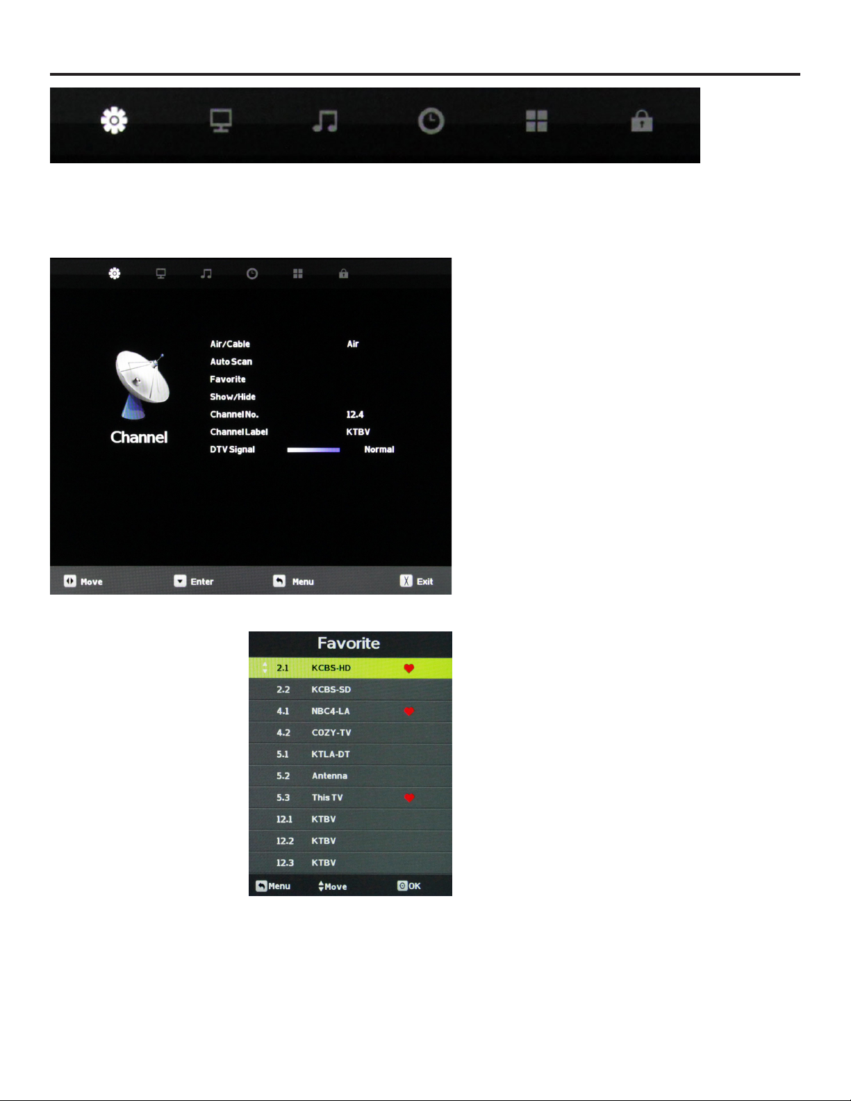
Adjusting On-Screen Displays – Channel Menu
1. Press the qp buttons on the remote or CH+/CH- on the TV) to move the cursor to the item to be selected.
2. Press the t u buttons on the remote or VOL+/VOL- on the TV to make the desired adjustments.
3. When your adjustments are complete, press MENU or EXIT on the remote or MENU on the TV to exit the main menu.
The Channel Menu is available only when TV is selected as the
source. To select TV as the source, push the SOURCE button
on the remote repeatedly until TV comes up as the source in
the onscreen display. Or push the INPUT button on the side
of the TV, then push the CH+ or CH- button on the side of the
TV repeatedly until TV comes up as the source in the onscreen
display.
Air/Cable
Press the qp buttons to highlight the Air/Cable adjustment.
Press the t u buttons to select Air (antenna) or Cable.
Auto Scan
Press the qp buttons to highlight the Air/Cable adjustment.
Press the u button to begin the Auto Scan process. A screen
will appear with the message “Are You Sure You Want to Auto
Scan?” Press the t button to begin Auto Scan, or u to go back
to the Menu. Auto Scan will automatically build a list of the
stations your TV can receive through the antenna or cable. The
scan process will typically take 3 to 5 minutes.
Favorite
Press the qp buttons to highlight the Air/Cable adjustment.
Press the u button to enter the favorite channel submenu
seen at left. This will allow you to select specic channels as
your favorites, which you can access by pressing the Favorites
button on the remote control.
To add a channel to your favorites list, press the qp
buttons to highlight the channel. Press the button to enter
the channel as a favorite. You will see a red heart appear next
to the channel in the list.
To delete a channel from your favorites list, press the qp
buttons to highlight the channel. Press the button to
delete the channel from your favorites. The red heart next to
the channel will disappear.
SunBriteTV Model DS-4720 Operator’s Manual
Page 23
Page 24
Adjusting On-Screen Displays – Channel Menu (continued)
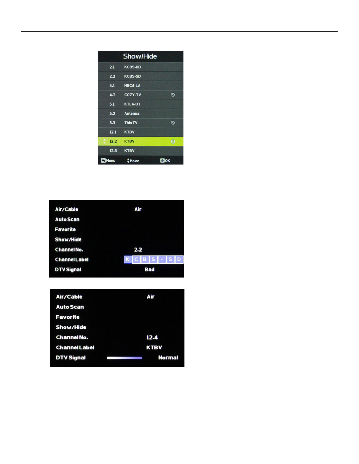
Show/Hide
Press the qp buttons to highlight the Show/Hide
adjustment. Press the u button to enter the Show/Hide
submenu seen at left. This will allow you to delete specic
channels from the channels that will appear when you use the
CH+/CH- buttons on the remote or on the TV.
To delete a channel from your CH+/CH- channel scan, press
the qp buttons to highlight the channel. Press the
button to delete the channel from the scan list. You will see a
character appear next to the channel in the list.
To restore a channel to your CH+/CH- channel scan, press the
qp buttons to highlight the channel. Press the button
to restore the channel from the scan list. You will see the
character next to the channel disappear.
Channel No.
Press the qp buttons to highlight the Channel No.
adjustment. Press the t u buttons to change the channel
number for which you wish to change the Channel Label or
view the signal strength on the DTV Signal meter.
Channel Label
Press the qp buttons to highlight the Channel Label
adjustment. Press the u button to enter the Channel Label
mode. As seen in the screen at left, a selection window will
appear over the existing channel name.his will allow you to
change the name of the channel as it appears onscreen when
you select it.
Press the qp buttons to change the highlighted letter
or character. Press the u button to move on to the next
character, and repeat the process until the new channel name
is entered. A total of seven characters is available for each
channel label.
DTV Signal
This meter, shown near the bottom of the image at left,
indicates the signal strength of the channel shown in the
Channel No. item of the menu. The longer the horizontal bar
appears, the better the signal strength. If the signal strength
is extremely poor, no meter will appear and the menu will
simply say Bad.
Page 24
Page 25
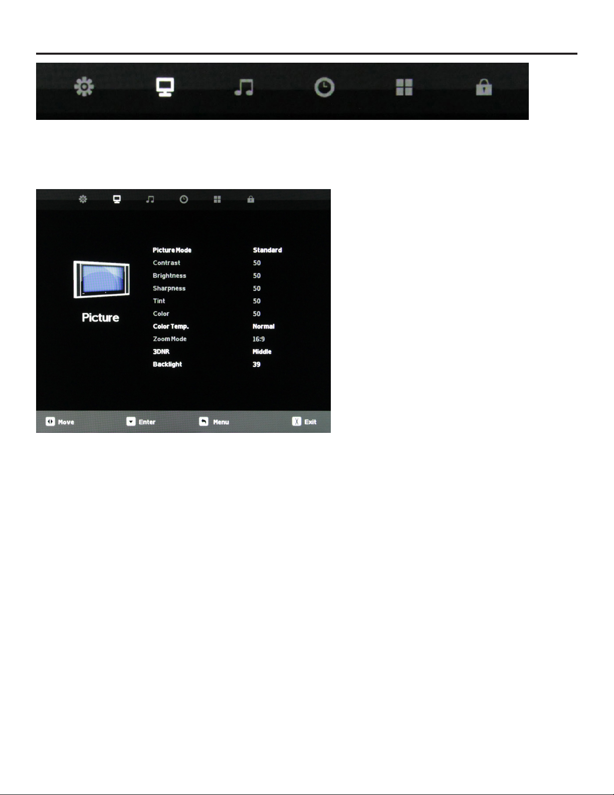
Adjusting On-Screen Displays – Picture Menu
1. Press qp buttons on the remote or CH+/CH- on the TV) to move the cursor to the item to be selected.
2. Press t u buttons on the remote or VOL+/VOL- on the TV to make the desired adjustments.
3. When your adjustments are complete, press MENU or EXIT on the remote or MENU on the TV to exit the main menu.
Picture Mode
Press the qp buttons to highlight Picture Mode, then
use t u to select Standard, Dynamic, Theater or Personal
picture mode.
Contrast
Press the qp buttons to highlight Contrast adjustment,
then use t u to adjust contrast. This adjustment is available
only when Personal picture mode is selected.
Brightness
Press the qp buttons to highlight Brightness adjustment,
then use t u to adjust brightness. This control is active only
when Personal picture mode is selected.
Sharpness
Press the qp buttons to highlight Sharpness adjustment,
then use t u to adjust sharpness. This control is active only
when Personal picture mode is selected.
Tint
Tint adjustment is not supported on this model.
Color
Press the qp buttons to highlight the Color adjustment,
then use t u to adjust color saturation. This control is active
only when Personal picture mode is selected.
Color Temperature
Press the qp buttons to highlight Color Temp. adjustment,
then use t u to select Normal, Warm or Cool color
temperature.
Zoom Mode
Press the qp buttons to highlight Zoom Mode adjustment,
then use t u to select picture zoom mode. With HDMI, the
choices are 16:9, 4:3, or Point to Point. With other signals, the
choices are 16:9, 4:3, Full or Zoom.
3D Noise Reduction
Press the qp buttons to highlight 3DNR adjustment, then
use t u to select O, Weak, Middle or Strong NR mode.
SunBriteTV Model DS-4720 Operator’s Manual
Backlight
Press the qp buttons to highlight Backlight adjustment,
then use t u to adjust backlight brightness.
Dynamic Light Control
Press q button when you are at the bottom of the Picture
menu to highlight DLC , then use t u to turn DLC on and
o. DLC automatically optimizes brightness and contrast for
the program you’re watching.
Page 25
Page 26
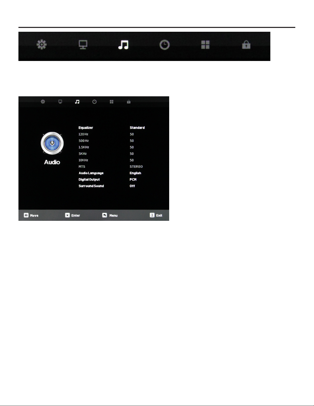
Adjusting On-Screen Displays – Audio Menu
1. Press qp buttons on the remote or CH+/CH- on the TV) to move the cursor to the item to be selected.
2. Press t u buttons on the remote or VOL+/VOL- on the TV to make the desired adjustments.
3. When your adjustments are complete, press MENU or EXIT on the remote or MENU on the TV to exit the main menu.
Equalizer
Press the qp buttons to highlight Equalizer, then use t u to
select Standard, Music, Movie, Sports or Personal sound mode.
120 Hz
Press the qp buttons to highlight 120 Hz, then use t u to
adjust the 120 Hz (bass) audio band. This adjustment is availale
only when Personal sound mode is selected.
500 Hz
Press the qp buttons to highlight 120 Hz, then use t u
to adjust the 500 Hz (lower midrange) audio band. This
adjustment is availale only when Personal sound mode is
selected.
1.5 kHz
Press the qp buttons to highlight 1.5 kHz, then use t u
to adjust the 1.5 kHz (upper midrange) audio band. This
adjustment is availale only when Personal sound mode is
selected.
5 kHz
Press the qp buttons to highlight 5 kHz , then use t u to
adjust the 5 kHz (lower treble) audio band. This adjustment is
availale only when Personal sound mode is selected.
10 kHz
Press the qp buttons to highlight 10 kHz, then use t u to
adjust the 10 kHz (upper treble) audio band. This adjustment is
availale only when Personal sound mode is selected.
MTS
This function is supported only with analog broadcast signals,
which are no longer used in the U.S.
Audio Language
Press the qp buttons to highlight the Audio Language
adjustment, then use t u to select English, Spanish or
French. This function operates only with multiple-language TV
broadcasts, and not with any of the video inputs.
Digital Output
Press the qp buttons to highlight the Digital Output
adjustment, then use t u to select PCM or Raw (bitstream).
Use Raw only if the connected audio system can decode Dolby
Digital. This function operates only when TV is selected as the
source.
Page 26
Surround Sound
Press the qp buttons to highlight the Surround Sound
adjustment, then use t u to switch the surround sound eect
on and o.
Page 27
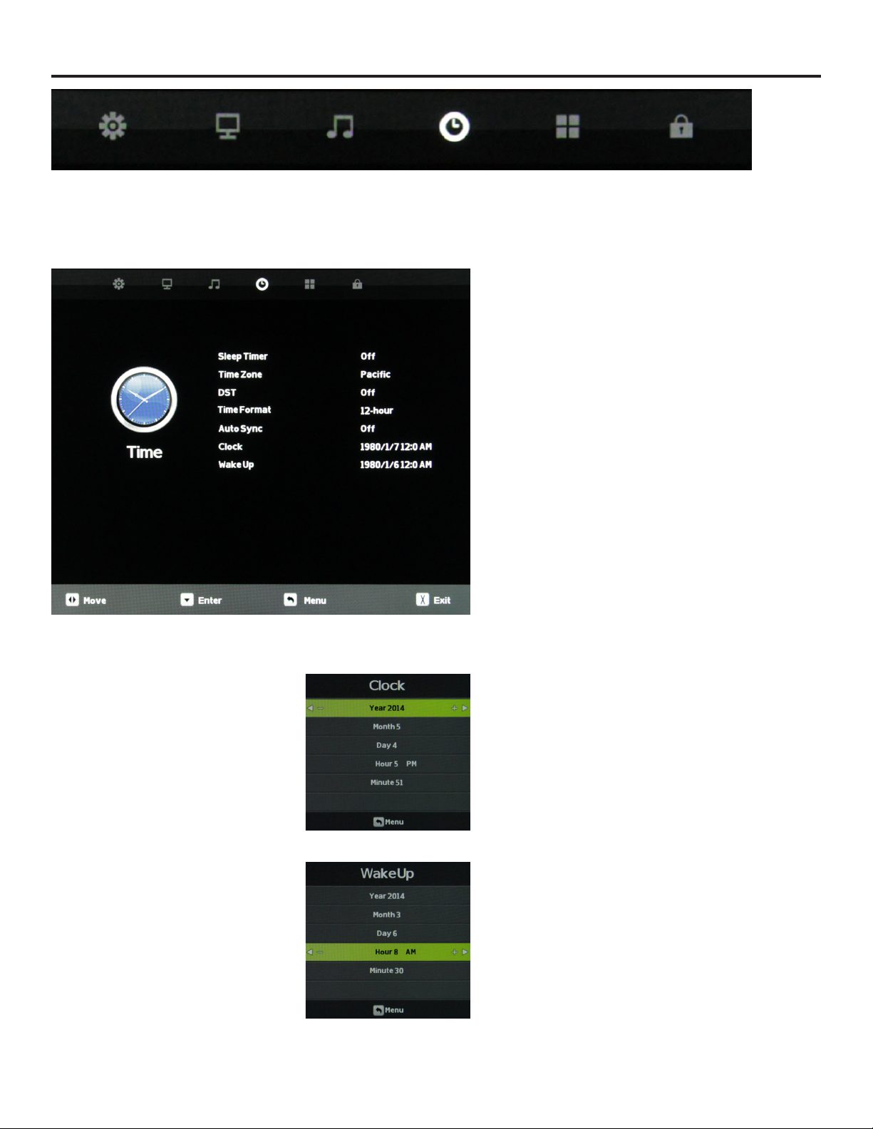
Adjusting On-Screen Displays – Time Menu
1. Press qp buttons on the remote or CH+/CH- on the TV) to move the cursor to the item to be selected.
2. Press t u buttons on the remote or VOL+/VOL- on the TV to make the desired adjustments.
3. When your adjustments are complete, press MENU or EXIT on the remote or MENU on the TV to exit the main menu.
Sleep Timer
Press the qp buttons to highlight Sleep Timer, then use
t u to select O or 5, 10, 15, 30, 60, 90, 120, 180 or 240
minutes. The TV will turn o automatically after the selected
time has elapsed.
Time Zone
Press the qp buttons to highlight the Time Zone
adjustment, then use t u to select Atlantic, Eastern,
Central, Mountain, Pacic, Alaska or Hawaii time zone.
Daylight Saving Time
Press the qp buttons to highlight the DST adjustment,
then use t u to turn daylight saving time on and o.
Time Format
Press the qp buttons to highlight the Time Format
adjustment, then use t u to select 12-hour or 24-hour.
Auto Sync
Press the qp buttons to highlight the Auto Sync
adjustment, then use t u to turn auto sync on and o.
Auto sync automatically sets the time on your TV based
on information from TV signals. Clock setting and DST
adjustments are not available when auto sync is activated.
Clock
Press the qp buttons to highlight the Clock setting
adjustment, then use t u to enter the Clock submenu
pictured at left.
Now press the qp buttons to highlight the adjustment
you want to make (day, hour, minute, etc.), then use t u to
make the adjustment. Repeat until the clock is set correctly.
Wake Up
This function allows the TV to turn on automatically at a
preset time. Press the qp buttons to highlight the Wake
Up setting adjustment, then use t u to enter the Wake Up
submenu pictured at left.
SunBriteTV Model DS-4720 Operator’s Manual
Now press the qp buttons to highlight the adjustment
you want to make (day, hour, minute, etc.), then use t u to
make the adjustment. Repeat until the desired wake up time
is set.
Page 27
Page 28
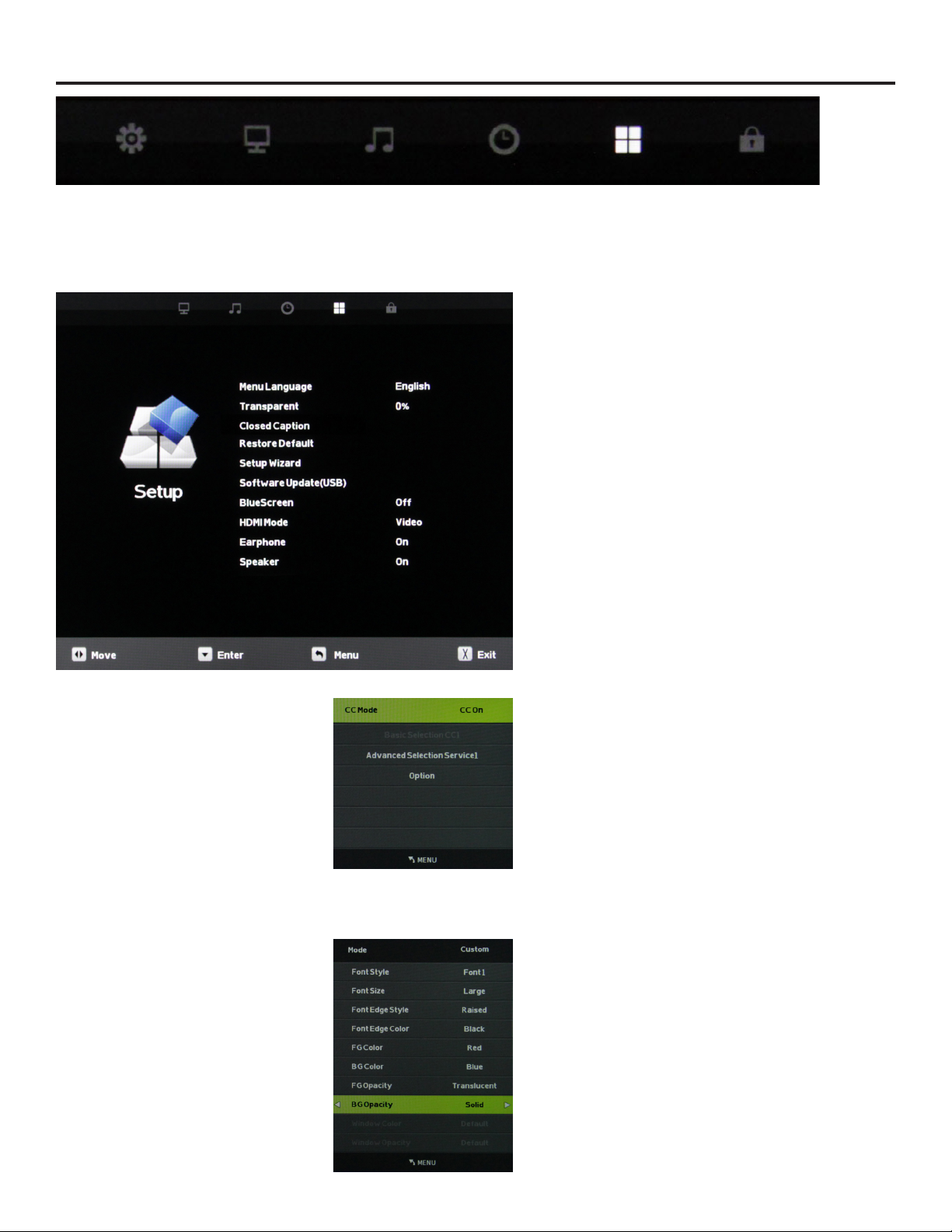
Adjusting On-Screen Displays – Setup Menu
1. Press qp buttons on the remote or CH+/CH- on the TV) to move the cursor to the item to be selected.
2. Press t u buttons on the remote or VOL+/VOL- on the TV to make the desired adjustments.
3. When your adjustments are complete, press MENU or EXIT on the remote or MENU on the TV to exit the main menu.
Menu Language
Press the qp buttons to highlight Menu Language, then use
t u to select English, French or Spanish.
Transparent
Press the qp buttons to highlight Transparent, then use
t u to select to what degree the picture shows through the
on-screen menus: 0%, 25%, 50%, 75% or 100%. At 0%, none of
the underlying picture will show through the menus.
Restore Default
Press the qp buttons to highlight Restore Default, then use
t u to bring up the Restore Default submenu. Press t to
restore the TV to factory settings, press u to cancel.
Closed Caption
This option appears only when TV is selected as the source.
Press the qp buttons to highlight Closed Caption, then use
t u to enter the CC Mode submenu shown at left. Pressing t
u will now select among the three closed caption modes: O,
On and CC on Mute. The last option shows captions only when
mute is activated.
Advanced Selection Services
When the CC Mode submenu is on-screen, press the qp
buttons to highlight Advanced Selection Services. Use t u to
select Advanced Selection Services O or 1-6. Availablility of
these services depends on the TV program.
Options
When the CC Mode submenu is on-screen, press the qp
buttons to highlight Options. This option is available only
when one of the Advanced Selection Services is selected. Use
the button to enter the Options submenu shown at left.
Now the t u will allow you to select Default or Custom
mode for the captions. In Custom Mode, you can use the qp
buttons to select dierent options, such as font style and size,
font color and background color, then use t u to adjust these
options.
Page 28
Page 29
Adjusting On-Screen Displays – Setup Menu (continued)
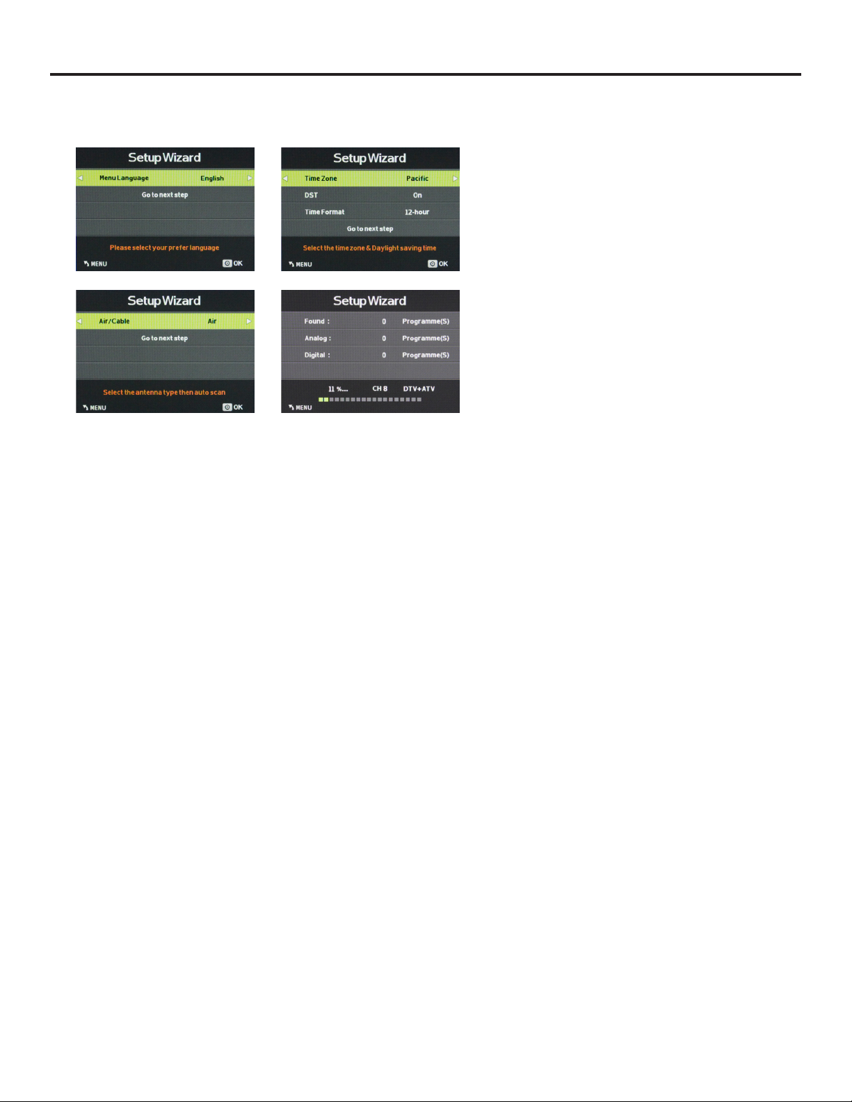
Setup Wizard
Press the qp buttons to highlight Setup Wizard, then use
t u to start the Setup Wizard. You will see the rst of four
submenus, all of which are shown at left. The Setup Wizard
will take you quickly through several basic settings on the
TV, incliuding Menu Language, Time Zone, DST on/o, Time
Format, Air/Cable and Auto Scan.
For each of the rst three menus, press the qp buttons to
highlight each setting to be adjusted, then use t u to make
the adjustment. When you’re nished with the adjustments
on a submenu, press q to highlight Go to Next Step, then
press t or u to go to the next screen of the Setup Wizard.
When you have nished with the third Setup Wizard screen,
the Setup Wizard will automatically activate Auto Scan to
identify and memorize the channels that can be received.
Software Update (USB)
This function is used to update the software on your TV.
Consult your dealer or SunBrite TV for more information.
Blue Screen
Press the qp buttons to highlight the Blue Screen
adjustment, then use t u to activate or deactivate the
blue screen that appears when no signal is available at the
selected input.
HDMI Mode
Press the qp buttons to highlight the HDMI Mode
adjustment, then use t u to select Video or PC HDMI mode.
The PC mode shows every pixel in the image. The Video
mode crops o a few percent of the image on each size and
zooms the cropped image in to ll the screen.
Earphone
The 3.5mm earphone output on the rear panel can be used
for headphones or as an audio output to feed a soundbar
or other external audio system. Press the qp buttons to
highlight the Earphone adjustment, then use t u to switch
the earphone output on and o.
Speaker
This control turns the TV’s internal speakers on and o. Press
the qp buttons to highlight the Speaker adjustment, then
use t u to switch the internal speakers on and o.
SunBriteTV Model DS-4720 Operator’s Manual
Page 29
Page 30
Adjusting On-Screen Displays – Setup Menu (continued)
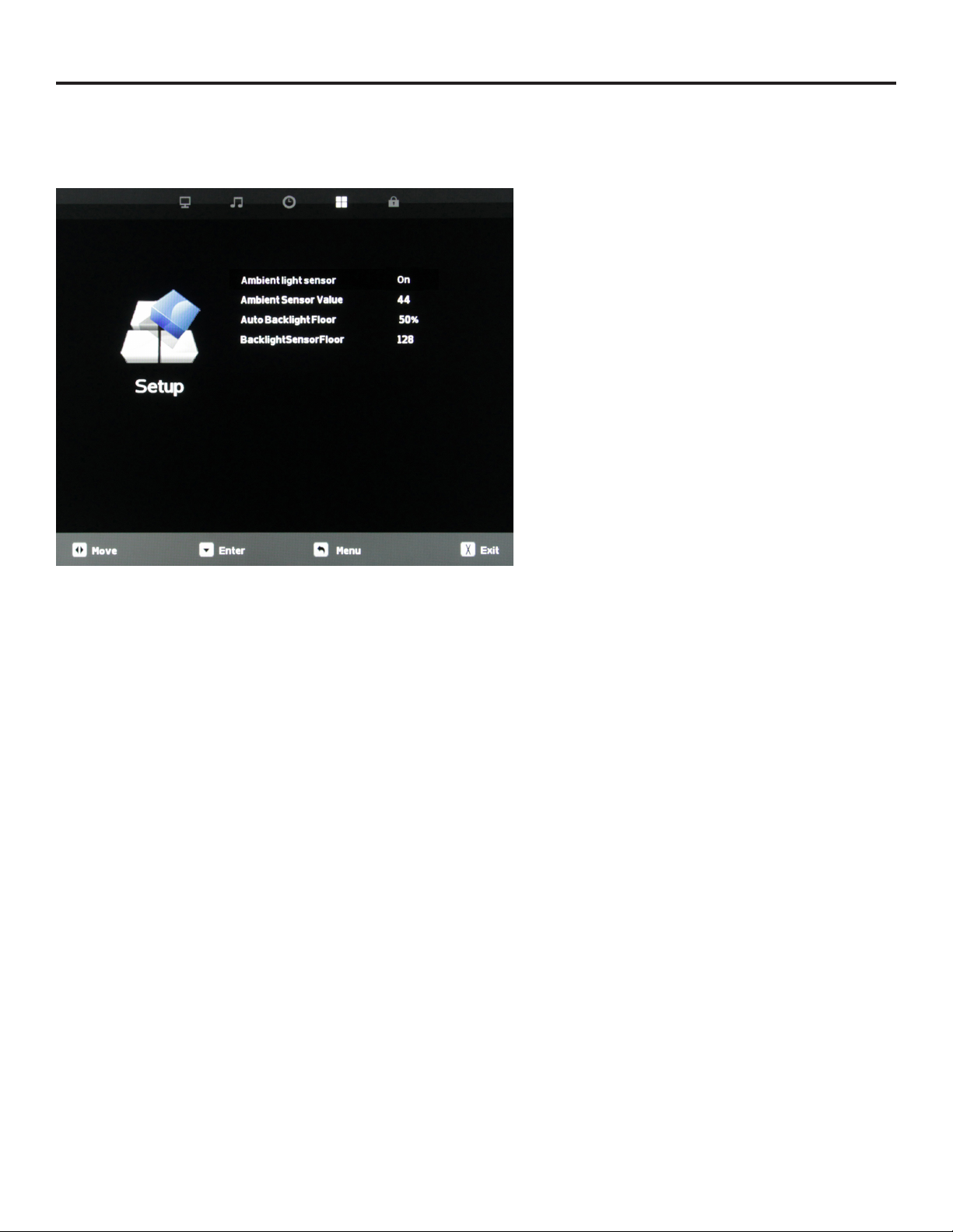
Ambient Light Sensor
Press the qp buttons to highlight the Ambient Light Sensor
adjustment, then use t u to turn the ambient light sensor
on and o. The ambient light sensor automatically measures
ambient light level and adjusts the backlight to the level
preset using the Auto Backlight Floor adjustment explained
below. When TV is selected as a source, you will have to go
all the way to the bottom of the Setup menu and press q to
reach this adjustment.
Ambient Sensor Value
This meter shows the level of ambient light as measured at the
light sensor on front of the TV (near the SunBright TV logo).
This shows the level of the ambient light. The value in the
meter remains xed until another menu item is highlighted. To
refresh the meter, press the qp buttons. Unless TV is selected
as the source, you will have to go all the way to the bottom
of the Setup menu and press q to reach this adjustment. This
adjustment is available only when the ambient light sensor is
activated.
Auto Backlight Floor
This adjustment sets the level to which the backlight will be
lowered when the ambient light level falls below the level set
on the Backlight Sensor Floor adjustment below. Press the
qp buttons to highlight the Auto Backlight Floor adjustment,
then use t u to set the auto backlight oor value. This
adjustment is available only when the ambient light sensor is
activated.
Backlight Sensor Floor
This adjustment sets the threshold for the automatic backlight
adjustment, governed by the ambient light sensor.
When the Ambient Light Sensor value is above the Backlight
Sensor Floor value, the backlight level will be 100%.
When the Ambient sensor value is below BackLightSensor
Floor value the backlight is reduced to the level set with the
Auto Backlight Floor adjustment.
Press the qp buttons to highlight the Backlight Sensor Value
adjustment, then use t u to set the backlight sensor value.
This adjustment is available only when the ambient light
sensor is activated.
Page 30
Page 31
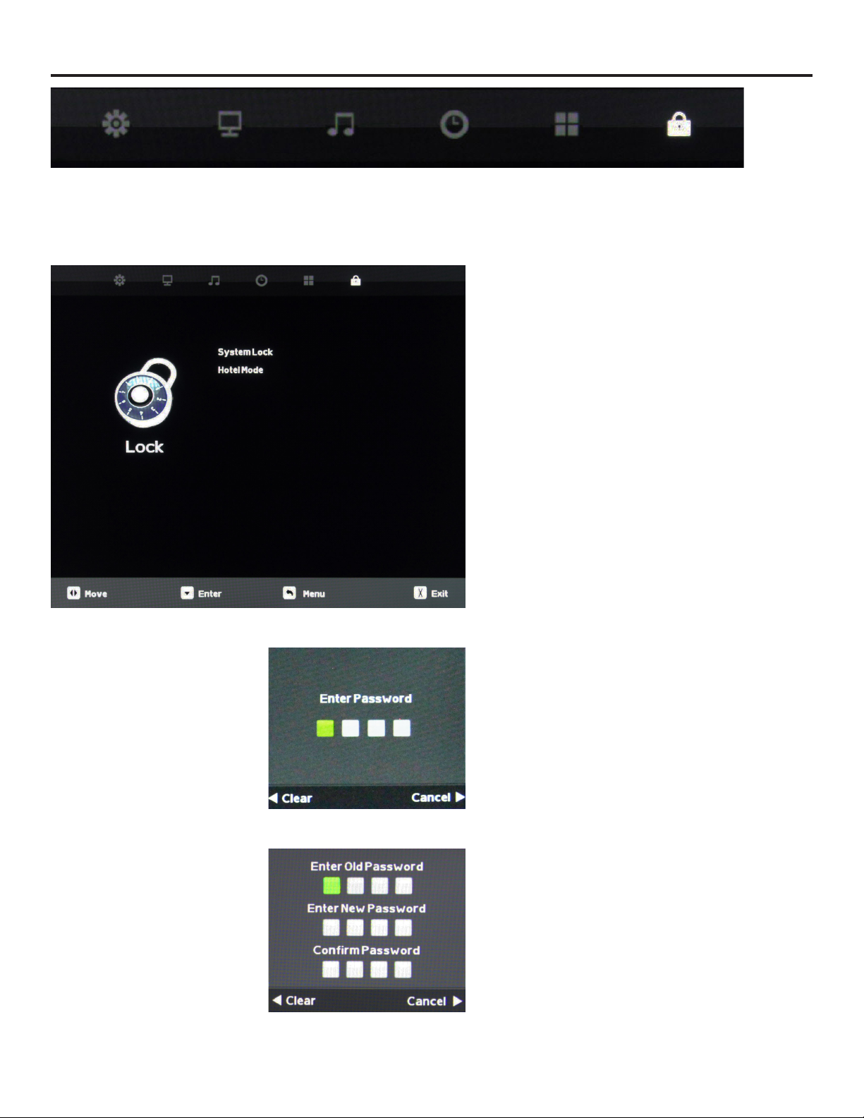
Adjusting On-Screen Displays – Lock Menu
1. Press qp buttons on the remote or CH+/CH- on the TV) to move the cursor to the item to be selected.
2. Press t u buttons on the remote or VOL+/VOL- on the TV to make the desired adjustments.
3. When your adjustments are complete, press MENU or EXIT on the remote or MENU on the TV to exit the main menu.
System Lock
Press the qp buttons to highlight System Lock, then use
t u to enter the Password menu shown at lower left. This
meun allows you to set a password that will be required
to access inputs that are locked out using the Input Block
feature described below. Selecting Hotel Mode will remove
the System Lock option from the menu until Hotel Mode is
deactivated.
You must enter the system password to acesss this feature.
See instructions below.
Hotel Mode
Press the qp buttons to highlight System Lock, then use
t u to enter the Password menu shown at lower left. This
menu allows you to set a password that will be required
to access inputs that are locked out using the Input Block
feature described below. Selecting Hotel Mode will remove
the System Lock option from the menu until Hotel Mode is
deactivated.
You must enter the system password to acesss this feature.
See instructions below.
Enter Password
You will have to enter the TV’s password to turn the System
Lock feature on and o. Use the numeric keypad on the
remote to enter the password. The default password is 0000.
You can change this password using the Change Password
feature in the menu.
Change Password
Press the qp buttons to highlight Change Password, then use
t u to enter the Change Password menu shown at left. To
change the password, use the numeric keypad on the remote
to enter the current password (0000 unless you previously
changed it), then enter the new password twice.
If you enter a new password but forget it later, contact your
SunBrite TV dealer for assistance.
SunBriteTV Model DS-4720 Operator’s Manual
Page 31
Page 32
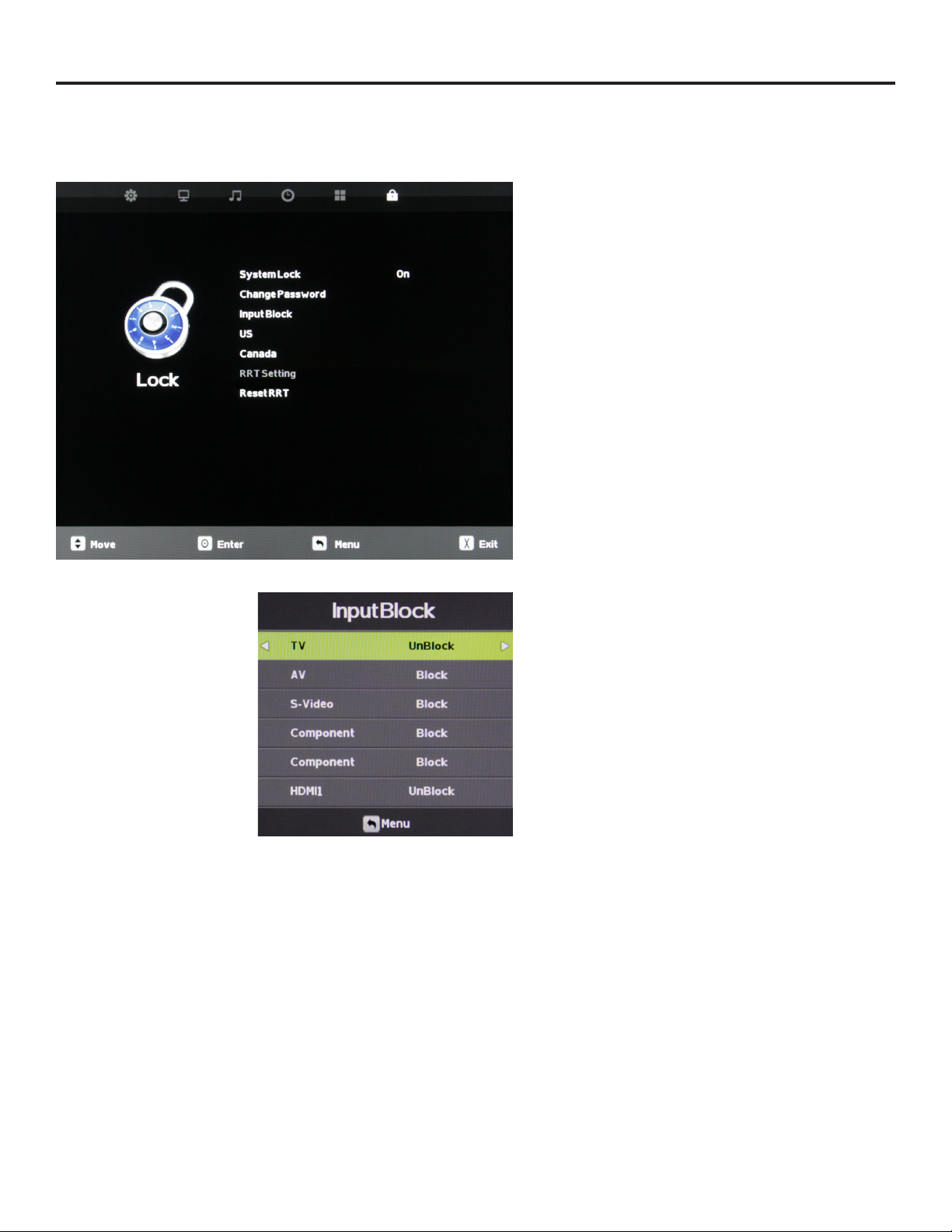
Adjusting On-Screen Displays – Lock Menu / System Lock Function
Using System Lock
Once you are in System Lock mode, press the qp buttons to
highlight the dierent functions in the menu, then use t u
to activate those features.
Input Block
To use the Input Block function, you must enter the Input
Block submenu shown at left. After activating System Lock
Mode, press the qp buttons to highlight the dierent inputs
in the submenu, then use t u to block or unblock those
inputs.
If an input is blocked, using it will require entering the system
password.
US
Canada
RRT Setting
Reset RRT
These functions are not adjustable and are for service use only.
Page 32
Page 33
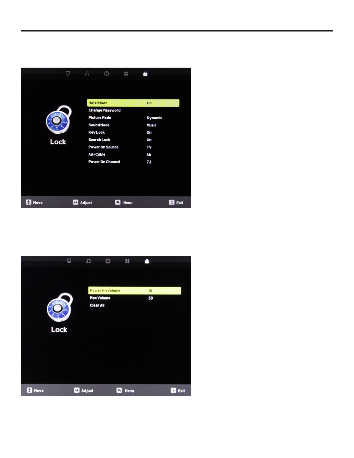
Adjusting On-Screen Displays – Lock Menu / Hotel Mode Function
Using Hotel Mode
Once you are in Hotel Mode, press the qp buttons to
highlight the dierent functions in the menu, then use t u
to activate those features.
Picture Mode
Press the qp buttons to highlight Picture Mode, then use t
u to choose among Dynamic, Standard, Theater and Personal
picture modes. This will be the preset picture mode for the TV,
changeable only by re-entering the Hotel Mode menu and/or
deactivating Hotel Mode.
Sound Mode
Press the qp buttons to highlight Sound Mode, then use
t u to choose among Music, Movie, Sports and Personal
sound modes. This will be the preset sound mode for the TV,
changeable only by re-entering the Hotel Mode menu and/or
deactivating Hotel Mode.
Key Lock
Press the qp buttons to highlight Key Lock, then use t u to
turn Key Lock on and o. Key Lock mode deactivates the sidepanel controls on the TV except for the power button.
Search Lock
Press the qp buttons to highlight Search Lock, then use t
u to turn Search Lock on and o. Search Lock mode prevents
activation of the Auto Scan channel scanning model without
entering the system password.
Power On Source
Press the qp buttons to highlight Power On Source, then use
t u to select among the dierent inputs. This is the source
that will be selected when the TV is turned on.
Air/Cable
Press the qp buttons to highlight Air/Cable, then use t u
to select Air (antenna) or Cable tuning for the TV input. This
selection cannot be changed without entering the system
password.
Power On Channel
Press the qp buttons to highlight Power On Channel, then
use t u to select the default TV channel that will come up
every time the TV is turned on.
Power On Volume
You can reach Power On Volume and the other settings
below by pressing the q button when Power On Channel is
highlighted. This will highlight Power On Volume. Use t u to
set the default volume level that will be set every time the TV
is turned on.
Max Volume
Press the qp buttons to highlight Max Volume, then use
t u to set the maximum volume level the TV can be turned
up to.
SunBriteTV Model DS-4720 Operator’s Manual
Clear All
Press the qp buttons to highlight Clear All, then use t u to
return all of the above adjustments to factory default settings.
Page 33
Page 34
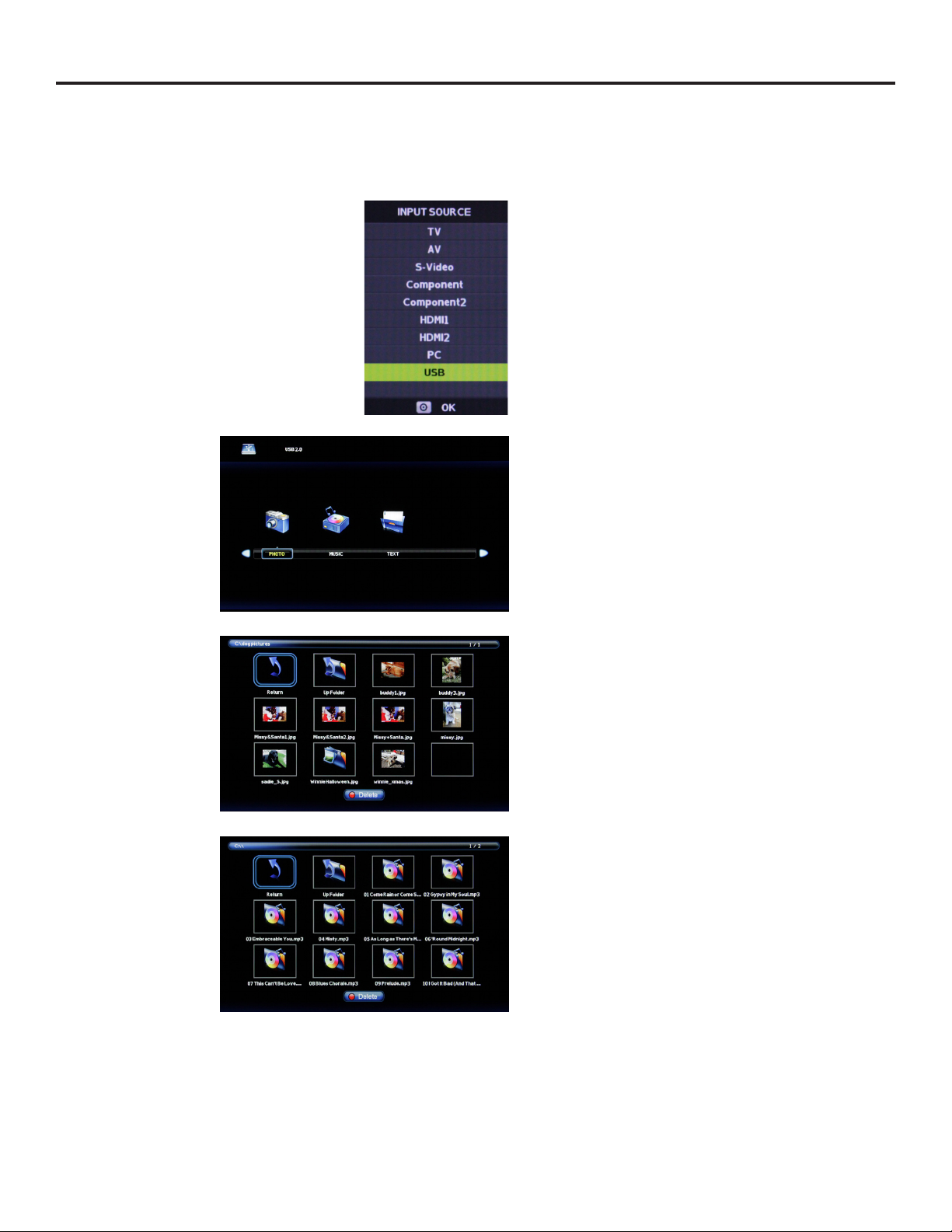
Using the USB Input
Using the USB input on the rear panel of the TV, you can access material stored on a USB stick. The material can be MP3 or
WAV music les, or JPEG or BMP pictures. The TV also has the ability to display the rst few sentences of plain text (.TXT)
documents, but because it shows only a few lines, this function is of very limiited use.
Accessing the USB input
Press the Source button on the remote or on the side control
panel of the TV, then press qp buttons to highlight USB.
Now press to select the USB input. The main USB menu
seen below left will appear.
Selecting the Media on the USB Stick
From the main USB menu seen at left, you can choose the type
of media you want to access: photos, music or text. Use
t u to highlight the type of media you want to watch, then
press to select a media type..
This action will take you either directly to media on the USB
stick, or to the folders on the stick that the media is stored in. If
foldera appeark, press t u to highlight the folder yuo want,
then press to open the folder.
Viewing Pictures from the USB Stick
Use t u to highlight the picture ou want to view, then press
to view that picture. The picture will appear, along with a
text screen that shows data about the picture. Note that the
picture will not fill the screen.
Listening to Music from the USB Stick
Use t u to highlight the tune you want to listen to, then
press to play the tune.. The music will begin playing, and a
text screen that shows data about the audio file will appear.
Page 34
Page 35
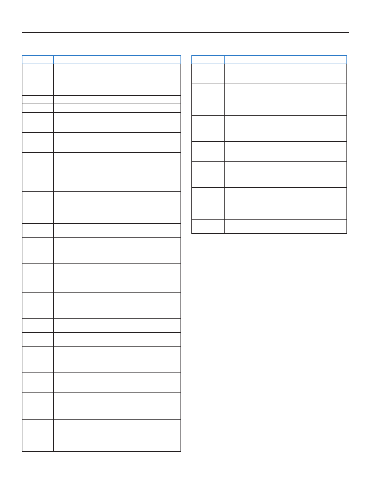
Troubleshooting
The following table contains the common problems and the solutions to these problems. Please check this list before you contact
the technicians.
Trouble Solutions
No picture Check the following: Power cord is connected correctly. Power is turned on.
Abnormal colors Match the colors on the cable to the connector. (Red cable to red colored port.)
Picture is too dark Adjust your contrast, brightness and backlight settings from the OSD menu
Audio only, no
picture
Picture only, no
audio
Remote control
does not work
Cannot receive
sucient
channels through
the ATSC/NTSC
Tuner
No color Adjust your picture setup and make sure the color saturation is not turned all the
Weak signal or no
program symbol
on screen
TV’s Universal
Remote Code
TV channels are
blocked
The TV turns on
or o slowly, and
the screen shows
up slowly
No sound from PC Make sure you have a 3.5 mm mini-jack cable connected from your PC’s sound
HDCP video says
no HDCP support
HDCP video has
no audio
Cannot get 1920
x 1080 from PC
VGA
Picture is
distorted or has
an abnormal
sound
Picture does not
cover the entire
screen
The video cable is connected correctly. You have selected the proper input signal
source.
If you have done the above, without resolve, unplug TV for at least 1 hour to
perform Hard Reset.
Make sure both the audio and video cables are connected.
The TV tuner signal must not be lower than 65 percent.
Unplug TV for at least 1 hour to perform Hard Reset.
Make sure the audio cable is connected.
Readjust your volume via the remote control.
The TV tuner signal must not be lower than 65 percent.
Turn o the TV, unplug it from the socket. Remove the batteries from the remote
for 30 minutes. Press the remote buttons and the power button randomly for 2 full
seconds, then reinstall the batteries.
The TV’s remote sensor is housed in the same place as the power indicator light.
Make sure there is line of sight from the remote control’s rst sensor to the remote
sensor of the TV.
The TV’s tuner signal must not be lower than 65 percent.
Change the direction of your antenna and re-scan the channels.
If you have cable, call the cable provider and ask to have your signal strength
checked.
way down.
The TV tuner signal must not be lower than 65 percent.
Change the direction of your antenna and re-scan the channels.
If you have cable, call the cable provider and ask to have your signal strength
checked.
This television follows Sony’s universal remote code. You may be able to nd
SunBriteTV’s code in your own universal remore’s guide book.
Check the Auto Lock function settings on the OSD. Channels may have been locked
previously.
This is a high denition liquid crystal display panel TV. It requires a few more
seconds than normal TVs to power up and show the picture.
output to the TV’s VGA Stereo Input.
Reboot your HDCP video device by turning it o, and unplugging the power cord.
Wait up to 8 minutes to plug the power back in to see if that works.
Make sure you have a 3.5 mm mini-jack cable connected from your HDCP video
device sound output to the TV’s VGA stereo input. If your HDCP video device uses
RCA audio jacks, you’ll need to obtain an audio cable with RCA plugs on one end
and a 3.5mm plug on the other.
The screen’s max resolution is 1920 x 1080. Your video card may not support this
resolution. Check your video card’s maximum resolution, and use that setting.
This might be from interference from large electrical appliances, cars, motorcycles
or uorescent lights. If the TV is close to the wall, try moving the TV to another
location to see if the problem still occurs.
If you are using HDMI or a TV digital channel, use the Aspect button to switch to
16:9 format. If you are using VGA, use the computer’s video controls to adjust the
image to the screen. Note: If you are watching regular 4:3 TV or 4:3 signals from
a VCR or DVD player in 480i resolution, use the Aspect button to switch to 16:9 in
order to ll up the screen. However, this feature will distort the picture.
Trouble Solutions
Picture quality is
very poor
Some pixels are
always displaying
the same color
Switching a
channel or source
changes the
volume
There is noise or
trash pixels on the
screen
Tips for highdenition users
Tips for letterbox
content users
The TV turns o
automatically
For best image quality, view HD widescreen programs. If HD content is not
available, use a digital source (DVD or Blu-ray player, digital satellite or digital
cable box). Standard 480i TV programs will be noticeably inferior to HD quality.
SunBriteTV LCD screens are manufactured to rigorous standards to maintain
optimal viewing. However, the LCD screen may have minor defects that appear
as a small bright or dark pixel. This is common to all LCD screens used in display
and television products, and is not specic to SunBriteTV. For more information,
see SunBriteTV’s Pixel Quality Policy in this manual.
Dierent channels and inputs sometimes have this eect because the channel
signal’s volume is pre-set.
When your TV’s resolution is higher than the digital channel’s broadcast
resolution, the signal is up-converted to match your TV’s resolution. Upconverting can cause this kind of eect.
The TV is an ideal platform for viewing high-denition content. The best image
quality can be achieved by HDMI, YPbPr (component), then VGA. However, due
to variances in broadcast practices, it is possible that some image distortion
may occur.
Letterbox (widescreen) versions of DVD movies are most commonly formatted
for standard 4:3 TVs. The TV has the capability of expanding this content so
the entire screen is lled, at the expense of the image proportion. To use this
function, press the Aspect button on the remote control and cycle among the
available options.
The TV features a power-saving mode which will automatically turn o the TV
if there is no signal provided for 15 minutes.
SunBriteTV Model DS-4720 Operator’s Manual
Page 35
Page 36
Care of SunBriteTV
Caring for the LCD Panel:
1. Cleaning the LCD Panel:
With your TV turned o, gently wipe the surface of the display panel with a damp (with water) microber, cotton or annel
cloth. (Do not use tissues, rags, sponges or paper towels because they may damage the screen and leave lint pieces behind).
If the LCD panel is very dirty, you can mix equal parts of isopropyl alcohol and distilled water in a clean spray bottle, spray the
mixture onto the cloth (do not spray the solution directly on the panel) and gently clean the panel.
A “special outdoor formula” LCD Cleaning Kit is now available and can be ordered from SunBriteTV.
2. When the TV is not in use, keep it covered with the SunBriteTV Outdoor Dust Cover:
The tted dust cover is designed to protect the LCD panel from the harmful UV rays from direct sunlight, and keeps windblown objects from scratching the surface of the panel.
To order a replacement Dust Cover or Cleaning Kit, contact your Authorized SunBriteTV dealer, SunBriteTV’s Customer
Care Center at 800.331.4626, or visit www.sunbritetv.com.
General Cleaning
Remove any dirt and salt deposits from the unit, being careful to rinse the cloth frequently to avoid scratching the TV or screen
surface. Avoid using harsh chemicals, abrasives, or solvents when cleaning any surface on the unit.
Snow and Ice
Use a soft brush and towel to remove snow and ice from the unit.
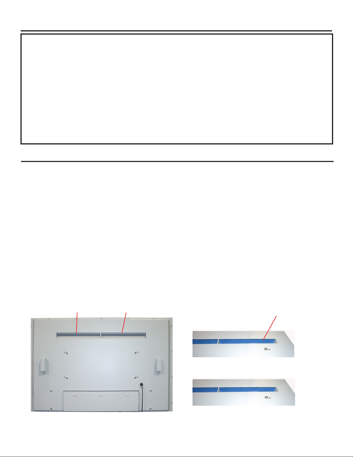
Fiber Filter
Over time, the ber lter collects dirt and must be cleaned or replaced periodically.
The Fiber Filter is located on the back of the unit, inside the Intake Vent at the top of the TV (Figure 1).
1. Release the Fiber Filter by pulling it out from the corner of the Intake Vent (Figure 2). Notice how the Fiber Filter ts in the upper
and lower channels, and tightly against the side.
2. Pull the Fiber lter out of the TV, and wash it with mild detergent and warm water. After rinsing, let the Fiber Filter dry completely.
3. Put the Fiber Filter back up into the Intake Vent pushing the lter rst into the upper channel, then t it into the lower channel.
Make sure lter ts tightly against the side. (Figure 3).
CAUTION! NEVER SPRAY OR DIRECT A HOSE INTO THE VENT AREA OF THE TV.
To Order Replacement Filters, contact SunBriteTV’s Customer Care Center at 800.331.4626.
Figure 1
Intake Vent
Exhaust Vent
Fiber Filter
Figure 2
Figure 3
Page 36
Page 37
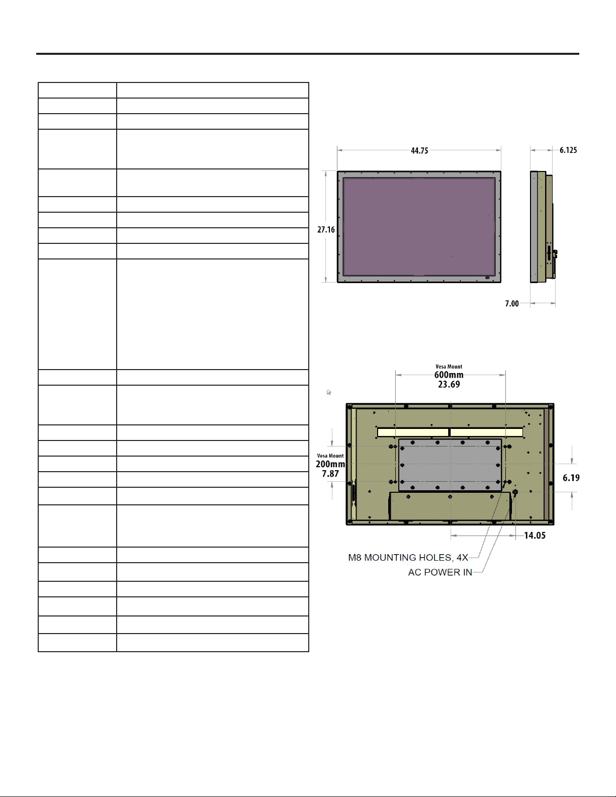
Specications
SunBriteTV Model DS-4720L
LCD Screen 47-inch diagonal Color Active Matrix LED LCD
Resolution 1920 x 1080 full-HD 1080p 120hz Frame Rate
Aspect Ratio 16:9
Blacklight Brightness
- Surface Luminance,
white
Ambient Light sensor auto dimming
Contrast Ratio 1300:1
Viewing Angle 176
Response Time 10 milliseconds
TV formats 1080p, 1080i, 720p, 480p, 480i
Input Connectors:
Tuner
HDMI
Video Composite
2000 nits (cd/m2)
Yes
o
Antenna/CATV (ATSC/QAM/NTSC) x1
HDMI™ Input x 2
S-Video x1 and Composite Video x1, L/R Audio Inputs x1
Side View Front View
All dimensions are in inches.
Video Component
PC
YPbPr plus Stereo Audio x2
15-pin D-sub VGA plus Stereo Audio
Control Set RS232 Serial, Discrete IR Control, Concealed rear IR Window
Audio Out Digital: SPDIF x 1(xed),
Analog: 1/8” headphone jack(variable),
Amplied: 10-watt x 2 channels @ 8ohm
Speakers Water-resistant detachable speaker module
Exterior Powder-coated aluminum
Colors Black and Silver
Input Power 100-240 VAC, 50-60 Hz 2.8 A Max (270w 2.25a @ 120VAC)
Operating Temp.
Non-op. Temp.
(O-mode with
power applied)
-24o to 122o F. (-31o to 50o C.) *
-24o to 140o F. (-31o to 60o C.)
The non-operating temperature feature requires power to
be applied
Accessories Included Water-resistant remote control
TV Dimensions 44.75” W x 27.16 ” H (29.33” H with speakers) x 6.25D
Weight TBD
Residential Warranty Two or Three year, in-factory, parts and labor
Commercial Warranty Two or Three year, in-factory, parts and labor
Mount Pattern 600mm x 200mm
Specications are subject to change.
Revised 06.27.2014
SunBriteTV Model DS-4720 Operator’s Manual
Page 37
Page 38

Features Information and Instructions
Programming Other Manufacturers’ Universal Remote Control Devices
When programming a DirectTV, local cable universal remote control or Control system, you may nd that SunBriteTV may not be on the
list of TV manufacturers. If that is the case, your SunBriteTV supports SONY’s universal remote code.
SunBriteTV Pixel Quality Policy
SunBriteTV’s Pixel Quality Policy
(Applicable to LCD TVs sold within USA and Canada only.)
SunBriteTV LCD screens are manufactured with rigorous standards to maintain optimal viewing. However, the LCD screen may
have minor defects that appear as a small bright or dark pixel. This is common to all LCD screens used in display and television
products, and is not specic to SunBriteTV.
Bright dots are dots that appear bright and unchanged in size when a LCD TV screen displays a black pattern.
Dark dots are dots that appear dark and unchanged in size when a LCD TV screen displays a pure red, green, or blue pattern.
Adjacent dots are pixels located directly next to each other.
Your SunBriteTV will be replaced under warranty if it meets one of the following criteria:
—A total of 7 defective pixels, including both bright dots and dark dots are present. (This LCD screen has over a million pixels.)
—2 or more pairs of adjacent bright dots are present.
—3 adjacent bright dots are present.
—3 adjacent dark dots are present.
To locate defective pixels, the LCD panel should be examined under normal operating conditions, in its native display resolution,
with a 90 degree viewing angle, from a distance of a approximately 20 inches.
To qualify for replacement, a defective LCD screen must be reported to SunBriteTV within 60 days from the day the customer
receives the TV.
For questions, please call our Customer Care Center at 800.331.4626.
Internal Thermostatically-Controlled Heater
The Internal Thermostatically-Controlled Heater keeps the unit warm in freezing temperatures and activates automatically when the
SunBriteTV internal temperature sensor reads a temperature inside the unit of 32O F. or lower. The heater remains on until the internal
temperature rises to at least 42O F. The heater provides a 20O F. temperature rise, allowing the TV to safely remain in temperatures as low
as -24O F. The ventilation fans are not activated when the heater is running and will automatically activate when required.
Note: In order for the automatic heater to work properly, your SunBriteTV must have power applied at all times.
Extreme Climate Warning
If temperatures below -24O F. are expected, we recommend that you bring your SunBriteTV inside to prevent damage to the LCD screen.
Page 38
Page 39
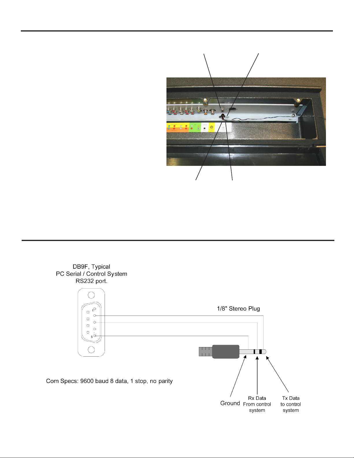
IR Emitter Installation
To install the IR Emitter:
The photo to the right shows an IR Emitter* installed.
The end of the Emitter is to be mounted in front of
the IR Emitter Window.
Place the emitter on the white tie-down block and
use the tie-down to secure it in place.
Place the emitter cable over the right or left side
of the cable box and connect the other end of the
emitter to the appropriate control block*.
* Neither the emitter or control block are supplied by
SunBriteTV. See instructions that come with your IR
Emitter and control block to determine how to make the
connections.
IR Window
Tie-Down Block
IR Emitter
Tie-Down
Place IR Emitter Cable
over right or left side of
the cable box.
Appendix A - RS232 Control Cable Pinout
SunBriteTV Model DS-4720 Operator’s Manual
Page 39
Page 40
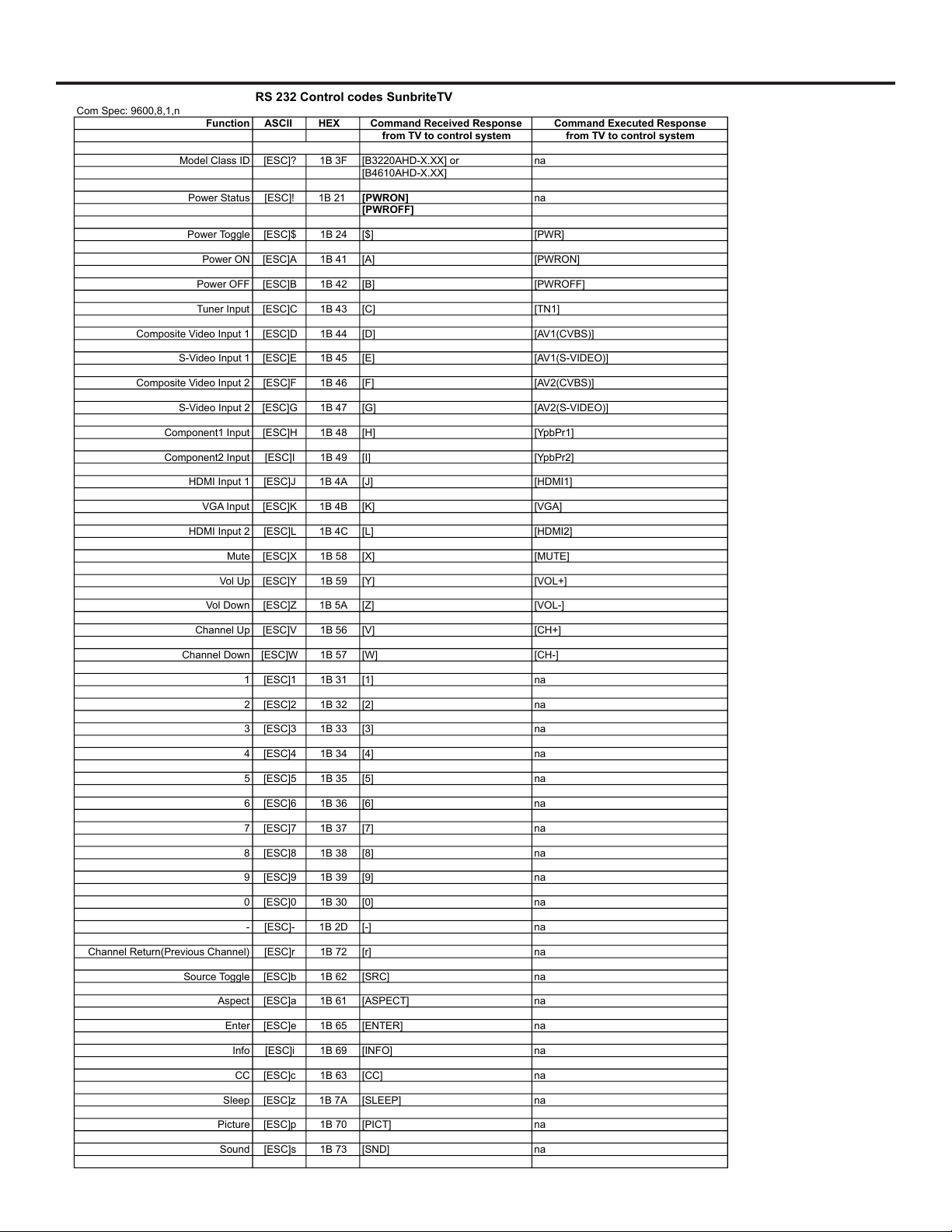
RS 232 Control codes SunbriteTV
Com Spec: 9600,8,1,n
Function ASCII HEX Command Received Response Command Executed Response
from TV to control system from TV to control system
Model Class ID [ESC]? 1B 3F [B3220AHD-X.XX] or na
[B4610AHD-X.XX]
Power Status [ESC]! 1B 21 [PWRON] na
[PWROFF]
Power Toggle [ESC]$ 1B 24 [$] [PWR]
Power ON [ESC]A 1B 41 [A] [PWRON]
Power OFF [ESC]B 1B 42 [B] [PWROFF]
Tuner Input [ESC]C 1B 43 [C] [TN1]
Composite Video Input 1 [ESC]D 1B 44 [D] [AV1(CVBS)]
S-Video Input 1 [ESC]E 1B 45 [E] [AV1(S-VIDEO)]
Composite Video Input 2 [ESC]F 1B 46 [F] [AV2(CVBS)]
S-Video Input 2 [ESC]G 1B 47 [G] [AV2(S-VIDEO)]
Component1 Input [ESC]H 1B 48 [H] [YpbPr1]
Component2 Input [ESC]I 1B 49 [I] [YpbPr2]
HDMI Input 1 [ESC]J 1B 4A [J] [HDMI1]
VGA Input [ESC]K 1B 4B [K] [VGA]
HDMI Input 2 [ESC]L 1B 4C [L] [HDMI2]
Mute [ESC]X 1B 58 [X] [MUTE]
Vol Up [ESC]Y 1B 59 [Y] [VOL+]
Vol Down [ESC]Z 1B 5A [Z] [VOL-]
Channel Up [ESC]V 1B 56 [V] [CH+]
Channel Down [ESC]W 1B 57 [W] [CH-]
1 [ESC]1 1B 31 [1] na
2 [ESC]2 1B 32 [2] na
3 [ESC]3 1B 33 [3] na
4 [ESC]4 1B 34 [4] na
5 [ESC]5 1B 35 [5] na
6 [ESC]6 1B 36 [6] na
7 [ESC]7 1B 37 [7] na
8 [ESC]8 1B 38 [8] na
9 [ESC]9 1B 39 [9] na
0 [ESC]0 1B 30 [0] na
- [ESC]- 1B 2D [-] na
Channel Return(Previous Channel) [ESC]r 1B 72 [r] na
Source Toggle [ESC]b 1B 62 [SRC] na
Aspect [ESC]a 1B 61 [ASPECT] na
Enter [ESC]e 1B 65 [ENTER] na
Info [ESC]i 1B 69 [INFO] na
CC [ESC]c 1B 63 [CC] na
Sleep [ESC]z 1B 7A [SLEEP] na
Picture [ESC]p 1B 70 [PICT] na
Sound [ESC]s 1B 73 [SND] na
Appendix B - RS232 Control Codes
Page 40
Page 41

SunBriteTV Model DS-4720 Operator’s Manual
www.sunbritetv.com
Page 41
 Loading...