

Santorini II 10-ft Square Cantilever Umbrella
with Sunbrella® Fabric
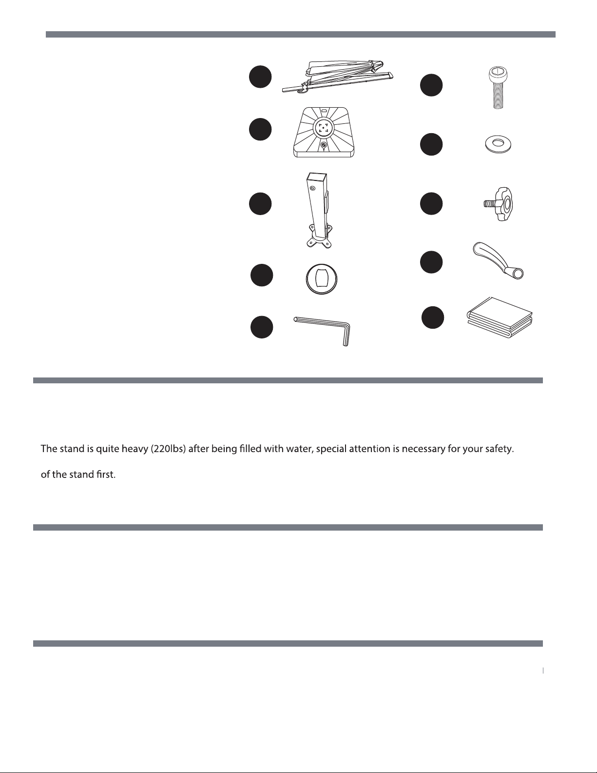
PACKAGE CONTENTS
A – (1) Main Umbrella*
B – (1) Plastic Water Fillable Stand
(incl. in separate carton as
A
F
NU6000JL)
C – (1) Base Pole, NUP4117
D – (1) Swivel Cover, NUP4118
E – (1) Allen Wrench, NUP4119
F – (4) Stainless Bolt, NUP4120
G – (4) Washer, NUP4121
H – (1) Threaded Knob, NUP4122
I – (1) Crank Handle, NUP4123
J – (1) Umbrella Cover, NUP4124
* For main umbrella replacement
please specify the item number
for your umbrella
B
C
G
H
I
D
J
E
SAFETY INFORMATION
Please read and understand this entire manual before attempting to assemble or install the product.
• Assemble on level ground.
• Keep children away from assembly area.
Two adults are required for safe assembly.
•
•
•
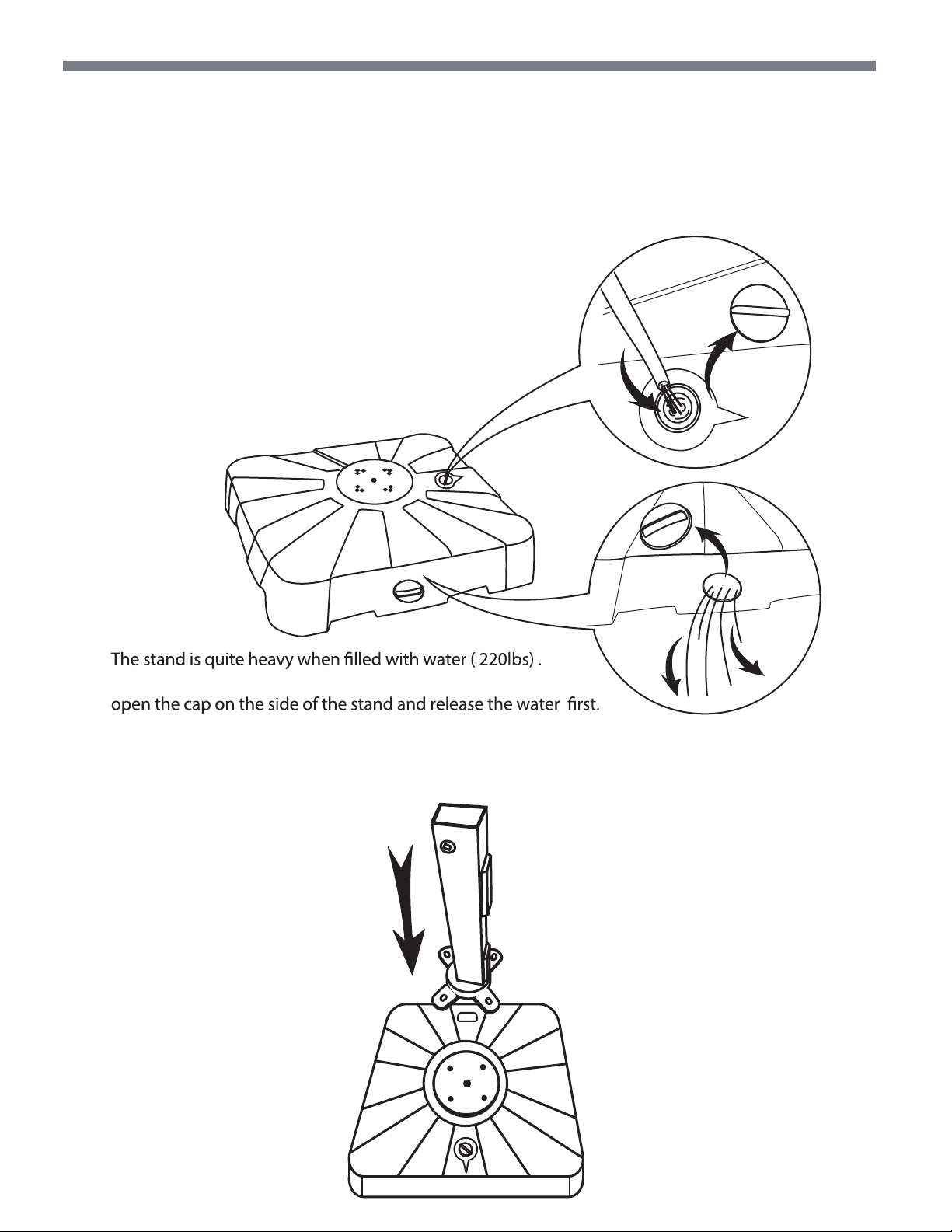
In case you want to move the umbrella to a new place, please close the umbrella and pour the water out
PREPARATION
Before beginning assembly of product, make sure all parts are present. Compare parts with package contents list.
If any part is missing or damaged, do not attempt to assemble the product.
Estimated Assembly Time: 10 Minutes
The tool for assembly is with the umbrella
CARE AND MAINTENANCE
Clean with mild soap and lukewarm water, rinse and air dry.
When not in use, close and cover the umbrella with a protective cover (included).
The umbrella must be closed in windy weather to avoid any damages.
Store the product indoors in a cool, dry place.
ASSEMBLY INSTRUCTIONS
Carefully check all packaging materials before discarding.
Do not assemble if there are missing pieces.
Step 1 Put the stand on a level ground where you intend to locate your umbrella.
Open the cap on the top of the stand & ll the stand with water.
Then tighten the cap.
In case you want to move the stand,
Step 2
Put the Base pole ( part C ) on the top of the
Plastic Water Fillable Stand
C
B
.
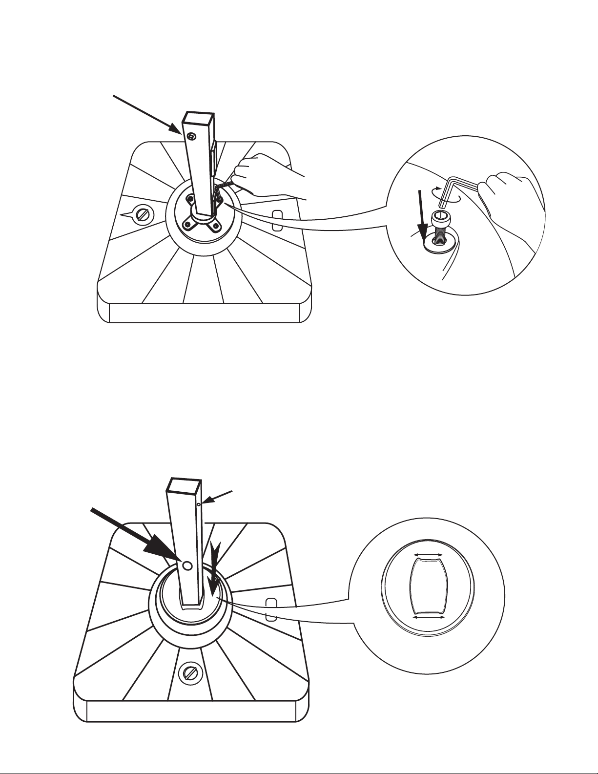
Step 3
Bottom crank hole
Fix the Base Pole ( part C ) on the top of the Plastic Water Fillable Stand ( part B ) with
bolts F & washers G use the Allen Wrench (E)
C
E
F
G
Step 4
Locking hole for threaded knob
Put the Swivel Cover ( part D ) around the Base Pole ( part C ) .
B
C
Bottom crank hole
side A
+/- 1.4”
B
D
Side B
+/-1.7”
side B
Important Notice :
Pay attention to the size of the middle hole in the Swivel Cover (part D).
Side A / Front Side : +/- 1.4" , Side B / Rear Side : +/- 1.7" .
Side B of the Swivel Cover (part D ) and the locking hole on the
Base Pole (part C ) must be at the same side.
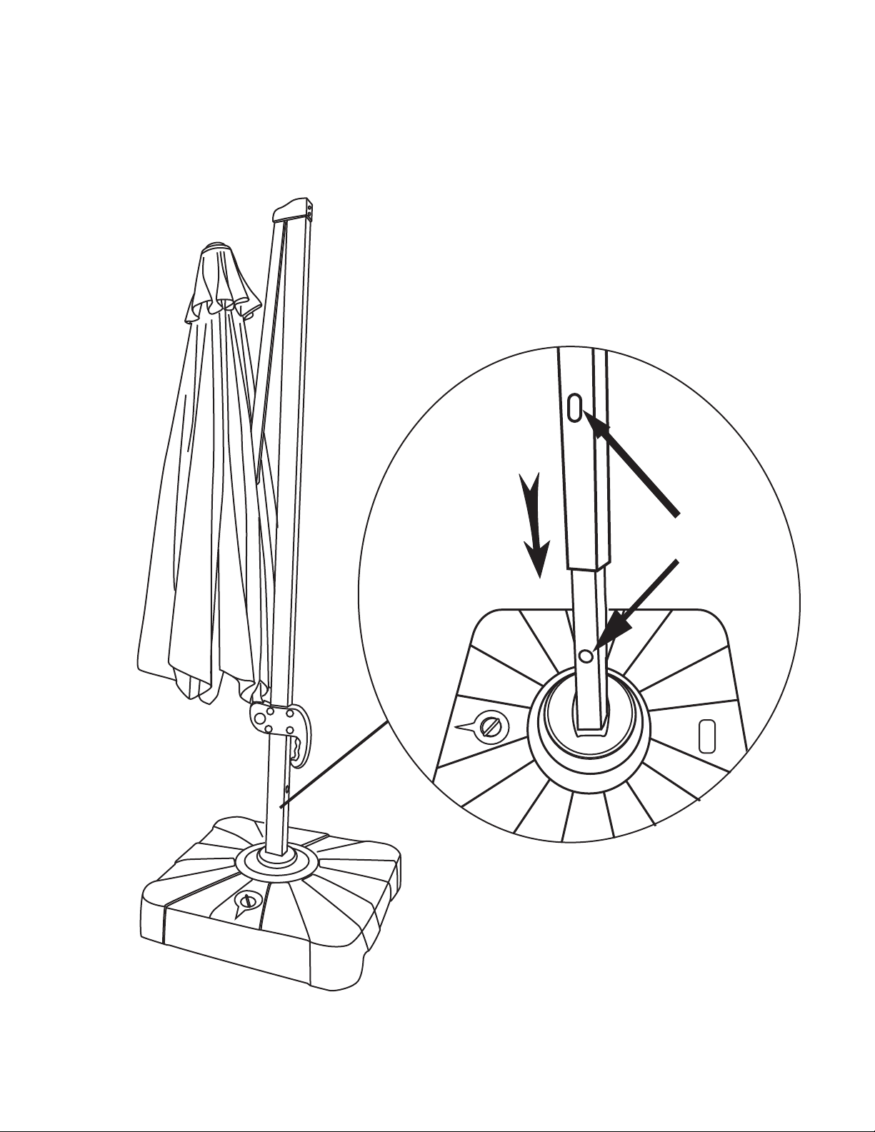
Step 5
A
Put the Main Umbella (Part A ) outside the Base Pole ( Part C )
Important Notice :
When you put the Main Umbrella outside the Base Pole,
make sure the locking holes are on the same side .
A
B
Locking hole for
threaded knob
B

Step 6
Fix the Threaded Knob ( Part H ) into the locking hole.
A
B
H

Step 7
Middle Crank Hole for umbrella opening and closing
There are 3 Crank Holes on your umbrella. Top crank hole for canopy tilting,
Bottom crank hole for 360 degree rotation. Middle crank hole for umbrella opening
and closing.
I
I
Bottom Crank Hole for 360 degree rotation
I
Top Crank Hole for canopy tilting

Step 8
1
Squeezing the trigger before attempting to raise the crank house. Fix the Crank Handle (I)
into the middle crank hole and turn clockwise to extend the umbrella fully .
A
I
2
I
Caution:
Please pull and loose the umbrella
ribs by hand before attempting to
open the umbrella by crank.
B

Step 9

Step 10
Fix the Crank Handle (I) into the top crank hole to tilt your umbrella canopy.
I

Step 11
Fix the Crank Handle (I) into the bottom crank hole to rotate your umbrella in
360 degrees.
I

Step 12 Squeezing the trigger before attempting to lower the crank house.
Turn the Crank handle counter-clockwise to close the umbrella.
First Step
Second Step
A
I
I
B
Step 13 When not in use, place Umbrella Cover (part J) over the umbrella .
 Loading...