


SUNBEAR HEAVY EQUIPMENT
DL165 Skid Steer Loader
Owner's
and
Operator's
Manual
PUBLICATION NO. 16500
SEPTEMBER, 2009


SUNBEAR HEAVY EQUIPMENT LIABILTY WARRANTY
THE WARRANTY IS THE ONLY OBLIGATION OF SUNBEAR HEAVY EQUIPMENT OR A
SUNBEAR HEAVY EQUIPMENT DEALER TO THE PURCHASER OR ANYONE ELSE
CONCERNING A PRODUCT. IT'S USE OR PERFORMANCE OR ITS LOSS OF USE OR FAILURE
TO PERFORM. NEITHER SUNBEAR HEAVY EQUIPMENT NOR A IMPLIED REPRESENTATION,
WARRANTY OR AGREEMENT CONCERNING A PRODUCT, NEITHER SUNBEAR HEAVY
EQUIPMENT NOR A SUNBEAR HEAVY EQUIPMENT DEALER HAVE MADE OR WILL MAKE
ANY REPRESENTATION, WARRANTY OR AGREEMENT CONCERNING A PRODUCT'S
MERCHANTABILITY OR OTHER QUALITY, IT'S SUITABILITY FOR PURCHASER'S PURPOSE
(EVEN IF A PURCHASER HAS INFORMED SUNBEAR HEAVY EQUIPMENT OR A SUNBEAR
HEAVY EQUIPMENT DEALER OF THAT PURPOSE), IT'S DURABILITY, PERFORMANCE OR
OTHER CONDITION.
EVEN IF SUNBEAR HEAVY EQUIPMENT OR A SUNBEAR HEAVY EQUIPMENT DEALER WAS
ADVISED OF THE POSSIBILITY OF SUCH LOSS, NEITHER SUNBEAR HEAVY EQUIPMENT
NOR A SUNBEAR HEAVY EQUIPMENT DEALER WILL BE LIABLE TO PURCHASER OR
ANYONE ELSE FOR ANY INDIRECT, INCIDENTAL CONSEQUENTIAL, PUNITIVE, ECONOMIC,
COMMERCIAL, OR SPECIAL LOSS WHICH IN ANY WAY ASSOCIATED WITH A PRODUCT.
THIS INCLUDES ANY LOSS OF USE OR NON-PERFORMANCE OF A PRODUCT, ANY
REPLACEMENT RENTAL OR ACQUISITION COST, ANY LOSS OF REVENUE OR PROFITS,
ANY FAILURE TO REALIZE EXPECTED SAVINGS, ANY INTEREST COSTS, ANY IMPAIRMENT
OF OTHER PERSON.
PURCHASER MAY NOT ATTEMPT TO ENLARGE ITS RIGHTS UNDER THE WARRANTY BY
MAKING CLAIM, FOR INEMNITY, FOR BREACH OF CONTRACT, FOR BREACH OF
COLLATERAL WARRANTY, FOR A TORT (INCLUDING NEGLIGENCE, MISREPRESENTATION
OR STRICT LIABILITY) OR BY CLAIMING ANY OTHER CAUSE OF ACTION.
THE WARRANTY IS A CONDITION OF SALE OF THE PRODUCT TO THE PURCHSER AND WILL
THEREFORE APPLY EVEN IF THE PURCHASER ALLEGES THAT THERE IS A TOTAL FAILURE
OF THE PRODUCT.
WARRANTY DELIVERY: TWO (2) YEARS 1000HOURS (FOR ONLY SAMPLES).
N.B. Read and practice your Sunbear Heavy Equipment operating and servicing instructions.
Failure to do this may void the warranty.
PUBLICATION NO. 16500
SEPTEMBER, 2009


INDEX
1. SAFETY PRECAUTIONS
2. CONTROLS
2. 1 Instrument Panel
2. 2 Control Lever Handles
2. 3 Seat and Seat Belt
2. 4 Seat Bar
2. 5 Parking Brake
2. 6 Throttle Control
2. 7 Lift Arm Support
2. 8 Steering Control
2. 9 Auxiliary Controls
2. 10 Liftarm Control
2. 11 Quick - Tach
2. 12 Electrical Panel
3. OPERATION
3. 1 Starting Instructions
3. 2 Operating Procedure
3. 3 Filling From a Pile
3. 4 Digging with a Bucket
3. 5 Leveling and Backfilling
3. 6 Auxiliary Hydraulics
3. 7 Lifting
3. 8 Towing
3. 9 Securing and Transporting
3. 10 Lowering Lift Arms
3. 11 Accumulator
4. MAINTENANCE
4. 1 Preventive Maintenance Service Schedule
4. 2 Service Access
4. 3 Daily Service Checks
4. 4 50 Hour Service Check
4. 5 250 Hour Service Check
4. 6 Final Drive Maintenance
4. 7 Hydraulic / Hydrostatic System Maintenance
4. 8 Engine Maintenance
4. 9 Air Cleaner Maintenance
4. 10 Engine Cooling System
4. 11 Electrical System
4. 12 Tire Maintenance
4. 13 Trouble Shooting
4. 14 Hydraulic / Hydrostatic Circuit
4. 15 Special Tools
5. SPECIFICATIONS
5. 1 Loader Specifications
5. 2 Torque Specifications
5. 3 Decals
6. A TTACHMENTS AND BUCKETS
6. 1 SUNBEAR Approved Buckets and Attachments


WARNING
This warning indicates
hazards or unsafe
practices which COULD
result in severe personal
injury or death.
This warning indicates an
immediate hazard which
WILL result in severe
personal injury or death.
DANGER
Instructions are necessary
before operating or
servicing this machine.
Read the operators manual
and service decals on the
loader. Follow warnings and
instructions in this manual
when making repairs,
adjustments or servicing.
Check for correct operation
after adjustments and
repairs.
IMPORTANT
This notice shows
important procedures
which must be followed
to prevent damage to the
loader or attachment.
IMPORTANT
This warning indicates
hazards or unsafe
practices which COULD
result in minor personal
injury or product or
property damage.
CAUTION
FOREWORD
This book has been written to give the Owner / Operator necessary operating,
servicing and preventative maintenance instructions on the loader.
Read this manual completely and know the loader before operating or servicing it.
Do not do any service procedures that are not in the Operator•s manual.
Only service personnel that have had training in the service of this loader can do these
service procedures.
Reference Information
Write the correct information for your loaders in the spaces below. Always use these
numbers when referring to your loader.
Model No.
Serial No.
Dealer Name
Address
Phone
Throughout this manual the terms DANGER, WARNING and CAUTION are used to
indicate the degree of hazard in terms of personal safety. These words will be used in
conjunction with the Safety - Alert symbol, a triangle with an exclamation mark.
Throughout this manual, the term IMPORTANT is used
* To indicate that instructions are necessary before operating or servicing the
loader.
* To show important procedures which must be followed to prevent damage to
the loader or attachment.


5
1. SAFETY PRECAUTIONS
The following precautions are suggested to help prevent accidents.
A careful operator is the best operator. Most accidents can be avoided by observing certain precautions. Read and take the
following precautions before operating this loader to help prevent accidents. Equipment should be operated only by those
who are responsible and instructed to do so.
1. Read this manual carefully before using the loader.
Working with unfamiliar equipment can lead to accidents.
2. Do not allow anyone to ride on the loader with the
operator.
3. Make sure the seat bar is installed and functioning at all
times.
4. Never run the engine in a closed building without
adequate ventilation, as the exhaust fumes can cause
death.
5. Always fasten the seat belt around your waist before
starting the engine. Never fasten the seat belt behind you.
6. Never attempt to start the engine while standing beside
the unit unless as specified in this manual or under
specific service and backhoe operation procedures. Start
the engine only while sitting in the operator•s seat with
the seat belt fastened around you. Always check to make
certain that the seat cushion is secured to the frame.
7 Keep the operator•s area free of debris.
8. Never enter or leave the loader while the engine is
running. Always lower the lift arms down against the
frame, drop the attachment down to contact the ground,
set the parking brake and shut off the engine prior to
leaving the loader.
9. If the unit is equipped with a cab enclosure kit always
close the door prior to operating the loader lift arms.
10. Do not operate the loader unless all safety equipment,
shields, seat belt, seat bar, hydraulic controls, parking
brake, operator guard, and lift arm support are working
properly, as well as all safety and instruction decals are in
place.
OPERATING THE LOADER
1. Always drive the loader at speeds compatible with safety,
especially when operating over rough ground, crossing
ditches or when turning.
2. Avoid jerky turns, starts, stops, or reverses.
3. Use care when operating on steep grades to maintain
proper stability.
4. Do not turn the loader while the lift arms are in the
raised position.
5. Be careful when driving through door openings or under
overhead objects. Always make sure there is sufficient
clearance for the operator•s guard.
6. When travelling on public roads, know the local rules and
regulations and make sure your loader is equipped with
the proper safety equipment.
7. Always be sure of water, gas, sewage and electrical line
locations before you start to dig.
8. Watch out for overhead and underground high-voltage
electrical lines when operating the loader.
9. Park the loader on level ground where possible. If the
loader is to be parked on an incline, always lower the
attachment so it contacts the ground, set the parking brake
and block the wheels.
10. Do not leave the loader when it is in motion.
11. Do not dismount from the loader and leave the loader lift
arms raised, unless following specific service procedures.
Always lower the lift arms down against the frame and
drop the attachment down to contact the ground.
12. Always be watchful of bystanders when operating the
loader.
13. Always carry the attachment low for maximum stability
and visibility.
14. Exercise extreme caution when operating the loader with
a raised attachment.
15. Never attempt to lift loads in excess of loader capacity.
16. Check that control lever functions are locked before
getting out of the operator•s seat.
17. Keep both hands on the control levers while the loader is
in motion.
MAINTENANCE
1. Stop the engine before performing any service on the
loader.
2. Never refuel the loader while smoking or with the engine
hot or running.
3. Replace all missing, illegible or damaged safety and
warning decals. See Section 5.3 for list.
4. Do not modify or alter, or permit anyone to modify or
alter this loader or any of its components or any loader
function.
5. Do not bypass the safety system. Consult your SUNBEAR
Equipment Dealer if your safety controls are
malfunctioning.
6. Do not make mechanical adjustments while the loader is
in motion or when the engine is running. However, if
minor engine adjustments must be made, securely block
the loader with the wheels clear of the ground, and use
extreme caution.
7. Do not attempt to repair or tighten hydraulic hoses when
the system is under pressure, when the engine is running
or when the lift arms are raised.
8. Do not get under the attachment or lift arms or reach
through the lift arms when they are raised.
9. Never attach the chains or ropes to the operator•s guard
for pulling purposes, as the loader can tip over.
10. Whenever servicing or replacing pins in cylinder ends,
buckets,
etc., always use a brass drift and a hammer.
Failure to do so could result in injury from flying metal
fragments.
11. Cooling system operates under pressure which is
controlled by the radiator cap. It is dangerous to remove
the cap while system is hot. Always turn cap slowly to the
first stop and allow the pressure to escape before
removing the cap entirely.
12. Keep the operator area free from debris.
13. For lifting and towing instructions, refer to Sections 3.7
and 3.8 of this manual.

To prevent personal
injury do not start the
engine unless you are in
the seat with the seat belt
fastened around you.
WARNING
To prevent personal
injury do not operate the
loader without lowering
the safety bar, fastening
the seat belt and keeping
feet on the cab floor.
WARNING
This engine is equipped
with glow plugs. Do not
use ether or any high
energy fuels to assist
starting.
IMPORTANT
C-359
6
1. SAFETY PRECAUTIONS
To avoid personal injury,
lower the lift arms, shut off
the engine, raise the seat bar
and cycle the hydraulics to
ensure they are locked.
Then, unlatch the seat belt
and exit the loader. Do not
enter or exit with the engine
running unless as specified
in this manual or under
specific service and backhoe
operating procedures.
WARNING
START SAFELY
1. Sit in the operator's seat and adjust it so you can operate
all of the controls properly.
2. Adjust the seat and fasten the seat belt. Cycle the
controls to make sure they are in the locked or neutral
position. Lower the seat bar.
3. Know the exact starting procedure for your machine.
See Section 3 for the manufacturer•s instructions for
starting.
PARK SAFELY
Select level ground whenever possible. If you must park
on a slope or incline, position the machine at right angles
to the slope. Lower the attachment to the ground, engage
the parking brake and block the wheels (C359).
C - 360

7
2. 1 Instrument Panel
2. 2 Control Lever Handles
2. 3 Seat and Seat Belt
2. 4 Seat Bar
2. 5 Parking Brake
2. 6 Throttle Control
2. 7 Lift Arm Support
2. 8 Steering Control
2. 9 Auxiliary Controls
2. 10 Liftarm Control
2. 11 Quick-Tach
2. 12 Electrical Panel
2. CONTROLS
2. CONTROLS

1. Left Signal Indicator Light: This light will
illuminate when the operator uses the optional left signal.
(Optional)
2. Auxiliary Front Indicator Light: This light will
illuminate when the loader auxiliary hydraulic front switch
is turned on. Light does not operate when lever switch is
depressed.
3. Hi-Flow Hydraulics Indicator: This light will
illuminate when the loader hi-flow hydraulics are in use.
(Optional)
4. Work Lights (Up) Indicator: The light will
illuminate when the loader work lights are turned on.
This will serve as a reminder to turn them OFF when the
loader is not in use.
5. Right Signal Indicator Light: This light will
illuminate when the operator uses the optional right signal.
(Optional)
6. Hydraulic Oil Temperature Indicator: This light
will illuminate when the oil temperature has exceeded
recommended levels. Shut off the engine immediately and
determine the cause.
7. Brake Light Indicator: The brake light will
illuminate when the parking brake is engaged.
8. Seat Belt Indicator Light: This light will illuminate
when the seat belt is unfastened.
9. Work Lights (Down) Indicator:
10. This light will
11.
The light will
illuminate when the loader work lights are turned on.
This will serve as a reminder to turn them OFF when the
loader is not in use.
14. Air Cleaner Indicator Light: This light will
illuminate when there is an obstruction in the intake or
when the air filter needs servicing. If this light illuminates,
stop the engine and service the cleaner.
8
2. CONTROLS
2.1 INSTRUMENT PANEL
K5250A
To prevent personal
injury do not start the
engine unless you are in
the seat with the seat belt
fastened around you.
WARNING
This engine is equipped
with glow plugs. Do not
use ether or any high
energy fuels to assist
starting.
IMPORTANT
1 2 3 4 5
1 2 3 4 5
6 7 8 9 10
6 7 8 9 10
11 12 13 14 15
11 12 13 14 15
16 17
000032H
1/10
½HOURMETER
0 FULL
21 22
18 19 20
23
12. Coolant Temperature Indicator Light: This light
will illuminate if there is a rise in engine temperature. If
this occurs, shut of
f the engine immediately and determine
the cause.
13. Alternator Indicator Light: This light will
illuminate when the alternator is not producing sufficient
current.
15. Pre-heat Indicator Light: This light will illuminate
when the ignition key is turned counter clockwise to
activate the engine glow plugs.
16. Headlight Switch: This is a toggle switch. Push up
to turn the dipped beam lights on. These lights are located
on the front of the loader.
17. Auxiliary Hydraulics Front Switch: This switch
is a toggle switch. Push up to provide a continous flow of
oil to the quick couplers when using an attachment.
Work Lights (Back) Indicator:
illuminate when the loader Back light are turned on. This
will serve as a reminer to turn them OFF when the loader is
not in use.
Engine Oil Pressure Indicator:
This light will
illuminate when the engine loses lubrication pressure. Shut
off the engine immediately and determine the cause.

9
This switch is a toggle switch
Push up to turn the dipped beam lights on. This light are
located on the rear of the loader.
2.2 CONTROL LEVER HANDLES
1. Spare
2. Spare
3, 4. Right / Left Direction Indicator (optional)
5. Horn
6. Spare
8. Auxiliary Hydraulic Switch
The left hand control lever is for moving the loader
forward and reverse. Pushing the lever forward will cause
the loader to move forward, and pulling the lever back
towards the operator will cause the loader to move in
reverse. This lever also operates hydraulic functions (refer
to section 2.8 for instructions).
The right hand control lever controls the lift arms and
bucket tilt. Pushing the lever forward will cause the lift
arms to raise, while pulling the lever back towards the
operator will cause the lift arms to lower. Moving the
control lever to the left and right will tilt and untilt the
bucket. Refer to section 2.10 for detailed operating
instructions of this lever.
Ensure liftarm brace is
properly stowed before
raising or lowering lift
arms
IMPORTANT
2. CONTROLS
LH Control Handle
RH Control Handle
1
3
2
4
5
6
8
7
Fig. 2.2A
C3933
18. Back Light Switch:
19. Door Window Wiper Switch: This switch is a toggle
switch. Push up to turn the wiper on.
20. Hi-Flow Hydraulic Switch: This switch is a toggle
switch. Push up to turn the Hi-Flow hydraulics on. (Not
available on all models)
21. Hour Meter: The hour meter records the number of
engine operating hours and has a total of 99999.9 hours.
22. Fuel Gauge: The fuel gauge indicates the quantity of
fuel remaining in the fuel tank.
23. Ignition Switch: The ignition switch is a three (3)
position switch: 'OFF', 'ON', 'RUN' and 'START'. Turn the
Turn the key counter clockwise to engage engine 'PREHEAT'. Turn the key clockwise to the 'START' position,
this engages the starter The key will be in the 'RUN' position
when released. Turn the key to 'OFF' to shut off the engine
and remove the key.
C3015
Fig. 2.2B

2. CONTROLS
2.3 SEATAND SEAT BELT
The seat can be adjusted forward or back for operator
comfort (Fig. 2.3A)
For your safety the loader is equipped with a seat belt.
Before starting the loader adjust and fasten the seat belt
(Fig. 2.3B) around you. The seat and seat belt also have
integrated safety lock switches whereby the operator must
be seated in the seat with the seat belt securely fastened
and seat bar lowered before the loader hydraulics can be
operated.
To prevent personal
injury do not start the
engine unless you are in
the seat with the seat belt
fastened around you.
WARNING
Fig. 2.3B
C2698
Fig. 2. 3A
C2699
Release
10

11
2. 4 SEAT BAR
For operator protection the loader is equipped with a seat
bar.
The loader must be started with the operator seated in the
loader and the seat bar in the up position. To raise the seat
bar, lift up on the bar (Fig. 2.4A). In the up position, the
seat bar activates the parking brake and locks out the
functions of the control levers including the auxiliary
hydraulics.
When down (Fig. 2.4B), the seat bar releases the park
brake and the hydraulic controls of the lift, tilt and
auxiliary hydraulic circuits.
Before exiting the loader always check the controls by
cycling them to ensure that they are in the neutral position.
2. CONTROLS
To avoid personal injury,
lower the lift arms, shut off
the engine, raise the seat bar
and cycle the hydraulics to
ensure they are locked. Then,
unlatch the seat belt and exit
the loader. Do not enter or
exit with the engine running
unless as specified in this
manual or under specific
service and backhoe
operating procedures.
WARNING
C5295
C5288
SeatBarUp
Fig. 2. 4A
SeatBarDown
Fig. 2. 4B

12
2. 5 PARKING BRAKE
The loader is equipped with park brakes, located inside the
torque motor. The brakes are activated and de-activated
by the seat bar, via charge pressure. When the seat bar is
in the up position, the brake is activated (Fig. 2.5A). When
the seat bar is in the down position, the brake is off (Fig.
2.5B).
The loader has a parking brake indication light to warn that
the brake is engaged. When the seat bar is in the down
position, activation of the emergency break can be carried
out by pushing on the button, located on the ROPS, in
front of the left hand control lever handle.
2. 6 THROTTLE CONTROL
The diesel engine throttle control is located on the left
hand side of the loader behind the control lever (Fig. 2.6).
Engine start and stop are controlled electrically by the
ignition key.
Before shutting off the engine, return the throttle control
to idle position and allow the engine to cool at least 2
minutes.
Pushing the lever full forward increases the engine speed
to maximum high idle. Pulling the lever back decreases
the engine RPM.
The engine should always be operated at full speed and
the loader travel speed controlled with the steering
control lever (See Section 2.8)
.
To avoid personal injury,
lower the lift arms, shut off
the engine, raise the seat bar
and cycle the hydraulics to
ensure they are locked.
Then, unlatch the seat belt
and exit the loader. Do not
enter or exit with the engine
running unless as specified
in this manual or under
specific service and backhoe
operating procedures.
WARNING
2. CONTROLS
Seat Bar Up
(ParkingBrakeon)
C5295 Fig.2.5A
Seat Bar Down
(ParkingBrakeoff)
C3776 Fig.2.5B
Throttle
Control
C5297
High
Speed
Low
Speed
Fig.2.6

13
2. 7 LIFT ARM SUPPORT
For safety while performing regular service or
maintenance work the loader is equipped with a liftarm
support.
The liftarm support, when engaged, prevents the liftarms
from dropping if hydraulic pressure is relieved or the right
hand control lever is accidentally cycled.
To operate the liftarm support, remove attachment and
park on level ground. Lower the liftarms to the ground and
stop the engine. Exit the machine and remove pin that
holds the liftarm support in stored positon(Fig. 2.7A).
Lower the liftarm support to rest on the lift cylinder(Fig.
2.7B). Re-enter the machine and re-assume proper
operating positon with the seat belt fastened and start the
engine. Slowly raise the liftarms until the support falls
onto the cylinder rod. Slowly lower the liftarms until
support restricts movement. Stop the engine.
T o remove the liftarm support, enter the loader and assume
proper operating position with the seat belt fastened and
start the engine, slowly raise the liftarms until the support
is free, have a helper pin the support into its stored positon,
lower the liftarms to the ground and shut off the engine
before exiting the loader.
2. 8 STEERING CONTROL LEVER
The left control lever controls speed, direction and turning
of the loader. Loader speed is controlled by the amount the
lever is moved from the centre or neutral position. (Fig.
2.8A) The further away from neutral, the faster the travel
speed. For maximum power and slow travel speed move
the control lever only a small amount.
T o drive the loader forward in a straight line, move the left
control lever forward from the neutral position (Fig.
2.8A).
To drive the loader in reverse in a straight line, move the
left control lever back from the neutral position (Fig.
2.8A).
The loader is turned by moving the left control lever to the
side. To turn right while in forward or reverse travel, ease
the control lever to the right. To stop turning, return the
lever to a center position. To turn left while in forward or
reverse travel, ease the lever to the left from the neutral
position. To stop turning, return the lever to a center
position (Fig. 2.8A).
For the loader to turn or "skid-steer" within its own length,
move the lever to the left or the right from the neutral
position. This causes the wheels on one side to turn
forward and the wheels on the other side to reverse turning
the loader (Fig. 2.8A).
2. CONTROLS
C5298
Fig. 2.7A
C5416
Fig. 2.8A
Liftarm Support,
Stored Position
Pin
Fig. 2. 7B
C 5299
Liftarm Support
Resting On Cylinder
C5415
Ensure liftarm brace is
properly stowed before
raising or lowering lift
arms
IMPORTANT
Forward Reverse
LeftTurn RightTurn
Forward
Left
Turn
N
Reverse
Right
Turn

14
2. CONTROLS
C5254
Fig. 2.9B
C5416
Fig. 2.9A
C5255
Fig. 2.9C
2.9 ELECTRIC SOLENOID
AUXILIARY CONTROLS
Auxiliary hydraulics (solenoid operated - standard) will
only operate with the seat bar down.
A switch located on the R.H. steering control lever (Fig.
2.8A) is used to engage the loader's auxiliary hydraulic
circuit to power attachments such as post hole augers,
sweepers, etc. Pressing and holding the switch in position
1 (fig. 2.8A) provides hydraulic flow to the female quick
connect coupling located at the front of the lift arms (fig.
2.8C). Releasing the switch returns the auxiliary hydraulic
circuit to neutral, stopping the hydraulic flow.
Pressing and holding the switch in position 2 (fig. 2.8A)
provides hydraulic flow to the male quick connect
coupling located at the front of the lift arms (fig. 2.8C).
releasing the switch returns the auxiliary hydraulic circuit
to neutral, stopping hydraulic flow.
For continuous flow to the auxiliary hydraulic circuit, a
toggle switch is located on the L.H. instrument panel (fig.
2.8B). Placing the switch in the "ON" position provides
continuous hydraulic flow to the female quick connect
coupling located at the front of the lift arms (fig. 2.8C). To
stop hydraulic flow to the auxiliary hydraulic circuit,
return the switch to the "OFF" position (fig. 2.8B). When
the switch on the instrument panel is in the "ON" position,
the switch located in the L.H. control lever is not operable.
NOTE: See Section 2.2 for information on the control
handles.
AUXILIARY HYDRAULIC CONTROL
1
2
NEUTRAL
TOGGLE
SWITCH
To avoid personal injury,
lower the lift arms, shut off
the engine, raise the seat bar
and cycle the controls to
ensure they are locked.
Then, unlatch the seat belt
and exit the loader. Do not
enter or exit with the engine
running unless as specified
in this manual or under
specific service and backhoe
operating procedures.
WARNING
Female Quick Coupling
Male Quick Coupling
ROPSSIDESEATSIDE

15
2. 10 LIFTARM CONTROLS
The right hand control lever (Fig. 2.10) operates the
loader•s liftarm and bucket hydraulic system. Refer to
section 2.8 for instructions on steering control.
When the control lever is in the neutral position, the lift
and tilt functions are static, the work attachment position
should not change unless the control lever is moved. If the
work attachment does move, service to hydraulic controls
is required.
Having the control lever in the neutral position does not
affect auxiliary hydraulics. Auxiliary hydraulics are
controlled separately and will continue to operate with the
control lever in the neutral position.
FLOAT (A)- Pushing the control lever all the way forward
will lock the lever in liftarm float detent. This float
position allows the work attachment to follow the contour
of the ground. Lever will remain locked in float position
until it is pulled out of float position.
LOWER (B)- To lower the liftarm, push the control lever
straight forward from the neutral position, the control lever
will return to the neutral position when released.
NEUTRAL (N)- Neutral (hold) position, lift and tilt
functions are static. Liftarms should hold their position.
RAISE(D)- Pulling the control lever back from the neutral
position will raise the liftarms, releasing the control lever
will allow it to return to the neutral position.
TILT BACK (E)- Moving the control lever to the left will
tilt the work attachment back (roll back bucket), releasing
the control lever will allow it to return to a neutral position.
TILT FORWARD (F)- Moving the control lever to the
right will tilt the work attachment forward (dump bucket),
releasing the control lever will allow it to return to a
neutral position.
By moving the control lever between two positons, both
functions can be done at the same time.
- Move the lever diagonally between lower and tilt forward
(B-F) to do both at the same time (lower and roll the work
attachment forward).
-Move the lever diagonally between raise and tilt back (DE) to do both at the same time (raise and roll the work
attachment back).
-Move the lever diagonally between raise and tilt forward
(D-F) to do both at the same time (raise and tilt the work
attachment forward).
-Move the lever diagonally between lower and tilt back
(B-E) to do both at the same time (lower and tilt the work
attachment back).
2. CONTROLS
To prevent personal
injury do not operate the
loader without lowering
the safety bar, fastening
the seat belt and keeping
feet on the cab floor.
WARNING
To avoid personal injury,
lower the lift arms, shut
off the engine, raise the
seat bar and cycle the
hydraulics to ensure they
are locked. Then unlatch
the seat belt and exit the
loader. Do not enter or
exit with the engine
running unless as
specified in this manual
or under specific service
and backhoe operating
procedures.
WARNING
C5413
Fig. 2.10
C5325
C5414
A
B
E
N
D
F

16
2.11 QUICK - TACH
The quick-tach, which is standard equipment, allows
changing from one attachment to another quickly without
having to remove bolt or pins.
To operate, (Fig. 2.11A), lift the locking lever (1) up to
completely retract the locking pins (2). Tilt the quick - tach
frame forward (Fig. 2.11B) with the bucket tilt cylinders and
drive into the attachment. Retract the bucket tilt cylinders
(Fig. 2.11C) which will line up the bottom of the attachment
with the quick - tach lock pins. Shut off the engine.
Push the locking lever (1) fully down (Fig. 2.11D) extending
the lock pins (Fig. 2.11E item 2) through the attachment and
securing the attachment.
Before operating the attachment check that the locking pins
are correctly engaged.
After hooking up the
attachment check to be
sure pins and locking
levers are correctly
engaged.
WARNING
C5359
C5410
Fig. 2.11B
Fig. 2.11A
C5412
C 5357
Fig. 2.11E
1
1
2
Fig. 2.11D
1
C5411
Fig. 2.11C
1
1
1
1
2
1
2. CONTROLS

17
2.12 ELECTRICAL PANEL
The loader is equipped with a 12 volt, negative ground
electrical system. The fuse and relay panel is located in the
engine compartment on the underside of the engine cover.
The panel consists of the following(Fig.2.12):
1. Engine Pre-Heater Relay.
2. Starter Relay.
3. Fuse Panel.
4. Turn Signal Flasher (optional)
5. Head Lamp. (20A)
FUSE PANEL (3)
6. Rear Lamp. (10A)
7. Wiper (15A)(Optional)
9. Front Horn. (10A)
10. Cigar Jack. (15A)
11. Aux, Hyd, Solenoid. (10A)
12. Alternator Light. (10A)
13. Brake Valve Solenoid. (10A)
14. Shut Down. (15A)
2. CONTROLS
Fig 2.12
8. Back up Alram. (10A)
C5256

18
3. OPERATION
3. 1 Starting Instructions
1. Pre-Starting Inspection
2. Starting Procedure
3. Shut-Off Procedure
3. 2 Operating Procedures
3. 3 Filling From a Pile
3. 4 Digging With a Bucket
3. 5 Leveling and Backfilling
3. 6 Auxiliary Hydraulics
3. 7 Lifting
3. 8 Towing
3. 9 Securing and Transporting
3. 10 Lowering Lift Arms
3. 11 Accumulator
3. OPERATION

19
3.1 STARTING INSTRUCTIONS
1. Pre-Starting Inspection
Before starting the loader complete the following inspection:
(1) Check the hydraulic oil level, engine oil level, engine
coolant level and fuel supply.
(2) Check for fuel, oil and hydraulic leaks.
(3) Check lights, battery level and cables.
(4) Check tire pressure:
10.00 x 16.5 . . . . 40 - 45 PSI (276 - 310 kPa)
(5) Check wheel nut torque 100 - 110 ft. lbs. (13.8 - 15.2
kgm) (136- 149 Nm).
(6) Lubricate all grease fittings.
(7) Check the condition and operation of all safety decals
and equipment … Ensure all shields and safety screens
are in place. If necessary repair or replace before
starting.
For complete daily servicing refer to section 4. 3.
2. Starting Procedure
1. Ensure the seat bar is in the UPposition and the control
levers are in neutral.
2. Adjust and fasten the seat belt securely around you.
3. Place the throttle control in idle position.
4. Turn the ignition key counter clockwise to activate the
glow plugs. Both the alternator and engine oil pressure
warning lights should be on. Use chart for correct pre-
heat times.
Glow Plug Pre-Heat Times
Ambient Temperature Preheat Time
0 C(32 F) and Above 10 Seconds
-18 C(0 F) to 0 C(32 F) 30 Seconds
-23 C(-10F) to -18C(0 F) 60 Seconds
-29 C(-20 F) to -23 C(-10 F) 120 Seconds
5. Turn the key clockwise to start position to engage the
starter. Do not crank the starter for more than 30
seconds. If the engine fails to start turn the key to off
position, wait one minute, and repeat the procedure. If
engine does not start after three attempts, check the
fuel suppply system. The absence of blue or white
smoke during cranking indicates that no fuel is being
delivered.
6. When the engine has started the engine oil pressure
and alternator warning lights should go out. If they
t, shut - off the engine immediately and determine
cause.
7. Allow the engine to warm up for five minutes before
operating. When ready to operate, lower the seat bar
and advance the throttle to full on position.
This engine is equipped
with glow plugs. Do not
use ether or any high
energy fuels to assist
starting.
Overvoltage (14 volts or
greater) will immediately
destroy the glow plugs.
Do not apply overvoltage
to the starting circuit at
any time. If boosting,
use a battery of equal
voltage to the loader and
connect it in
parallel,positive to
positive, negative to
negative.
Limit preheating to
recommended preheat
times; longer periods can
ruin the glow plugs.
IMPORTANT
IMPORTANT
IMPORTANT
3. OPERATION
To avoid personal injury
do not start the engine
unless you are in the seat
with the seat belt
fastened around you,
unless as specified in this
manual or under specific
service and backhoe
operating procedures
.
WARNING
To prevent personal
injury do not operate the
loader without lowering
the safety bar, fastening
the seat belt and keeping
feet on the cab floor.
WARNING
don'

WARNING
To avoid personal injury,
lower the lift arms, shut off
the engine, raise the seat bar
and cycle the hydraulic
controls to ensure they are
locked. Then, unlatch the seat
belt and exit the loader. Do
not enter or exit with the
engine running unless as
specified in this manual or
under specific service and
backhoe operating
procedures.
3. Shut-Off Procedure
(1) Select level ground whenever possible. If you must park on
a slope or incline, position the machine at right angles to the
slope. Lower the attachment to the ground, engage the
parking brake and bloke the wheels.
(2) Lower the lift arms and ground the attachment.
(3) Return auxiliary hydraulics to neutral or OFF position.
(4) Return the throttle control to idle position. If the engine is
hot allow it to idle until normal, at least 2 minutes.
(5) Never enter or exit the loader when the engine is running.
(6) Raise the seat bar to apply the park brake. Turn the ignition
switch to the OFF position, remove the key, unfasten the
seat belt, and ensure the hydraulic controls are locked by
rocking them.
3. OPERATION
3. 2 OPERATINGPROCEDURES
1. When learning to use the loader, operate at a slow rate.
2. Take advantage of the efficient operation of the loader.
Keep the travel distance as short as possible. Keep the work
area small so the cycle time is short.
3. Keep the work area as level as possible.
4. Decrease cycle time by "Skid" turning (See Section 2.8A)
rather than a go backward-go forward turn.
5. Fill the bucket to rated capacity . Turning is easier with a full
load than with a partial load. Keep the loaded bucket close
to the ground when transporting.
6. Tilt the bucket as you raise the lift arms or drive up a slope.
This will prevent material from falling off the back of the
bucket.
7. Do not drive across a slope. Always go up or down a slope
with the heavy end of the loader pointing up towards the top
of the slope.
C5363
20
Handle
Fig. 3.3

21
3. 3 FILLING FROM A PILE
Fig. 3.3A--Push ahead on the right hand control lever (1) and
lower the lift arms completely down. Push to the right on the
right hand control lever (2) and place the cutting edge of the
bucket on the ground.
Fig. 3.3B--Push ahead on left hand lever to drive the loader
forward slowly into the pile. As the bucket begins to fill pull
to the left on the right hand lever (3) to raise the front of the
bucket and pull back on the right hand lever (4) to raise the
lift arms. When the bucket is full back away from the pile.
Fig. 3.3C--To dump the bucket pull back on the right hand
control lever (4) to raise the lift arms, push to the right small
amounts as the lift arms are raising to stop material from
falling off the back of the bucket. When the bucket is at the
correct height for dumping, push to the right on the right hand
lever (2) to empty the bucket.
Always let the engine
warm completely before
you begin operation each
day.
IMPORTANT
3. OPERATION
Fig. 3.3A
C5303
Fig. 3.3C
C5304
C5305
1
2
3
2
4
4
Fig. 3.3B

22
3. 4 DIGGING WITH A BUCKET
Fig. 3.4D--Push ahead on the right hand control lever (1) and
lower the lift arms completely down. Push to the right on the
right hand lever (2) and place the cutting edge of the bucket
on the ground. Drive the loader forward at a slow rate and
continue to tilt the bucket down until it enters the ground.
Fig. 3.4E--Pull to the left on the right hand lever (3) to raise
bucket edge to increase traction and keep an even digging
depth.
Fig. 3.4F--Continue to drive forward until the bucket is full.
When digging in hard ground, it is easier to raise (3) and
lower (2) the bucket cutting edge with the right hand control
lever while slowly driving forward. When the bucket is full,
pull to the left on the right hand control lever (3) to roll back
the bucket.
To avoid personal injury:
When starting or
operating loader in an
enclosed area make sure
there is enough
ventilation. Exhaust
fumes can kill.
WARNING
3. OPERATION
Fig. 3.4D
To prevent personal
injury always carry the
load low.
WARNING
Fig. 3.4E
C5306
C5307
Fig. 3. 4F
To prevent personal
injury, ensure that the
bucket with the proper
rated capacity is being
used for the job you are
doing.
WARNING
1
2
3
3
2
C5308

23
3. 5 LEVELINGAND BACKFILLING
Fig. 3.5G--Spread dirt on uneven ground by pulling back on
the right hand control lever (4) to raise the lift arms and push
to the right on the right hand control lever (2) to tilt the bucket
down as you drive forward.
Fig. 3.5H--To level the ground; raise the lift arms and tilt the
bucket down by pushing to the right on the right hand control
lever (2). Push ahead firmly on the right hand control lever (1)
to lock the lift arms in the float position. The weight of the lift
arms and bucket will hold the bucket on the ground. Drive
backward to level material.
Fig. 3.5I--T o fill a hole drive the loader slowly with the bucket
low, up to the hole. As the bucket passes the edge of the hole,
push to right on the right hand control lever (2) to dump the
bucket. When necessary raise the lift arms to empty the
bucket.
3. OPERATION
Fig. 3.5H
C5309
Fig. 3.5G
To prevent personal
injury always carry the
load low.
WARNING
C5310
C5311
2
1
2
2
Fig. 3.5I
4

24
3. 6 AUXILIARY HYDRAULICS
Fig. 3.6J--To operate an attachment such as a grapple fork
the Auxiliary Hydraulic Control Switch (rocker switch) on
the Left Hand Control Lever will be used. Push right of
neutral on the Auxiliary Hydraulic Control Switch to open
the grapple.
Fig. 3.6K--To close the grapple, push left of neutral on the
Auxiliary Hydraulic Control Switch. The right hand
control lever can be used to raise and tilt the grapple as
with a bucket.
Fig. 3.6L--To operate an attachment which requires a
constant flow of oil, a toggle switch (AUX HYD) on the
L.H. instrument panel should be placed in the "ON"
position.
When the auxiliary circuit is not in use, switch AUX HYD
to the "OFF" position. Otherwise starting the loader may
be difficult or impossible to start and damage to the starter
may occur.
Return the auxiliary
control to neutral when
not in use otherwise
starting may be
impossible and damage
to the starter may occur.
IMPORTANT
3. OPERATION
Fig. 3.6J
Fig. 3.6K
To avoid personal injury,
lower the lift arms, shut off
the engine, raise the seat bar
and cycle the hydraulics to
ensure they are locked. Then,
unlatch the seat belt and exit
the loader. Do not enter or
exit with the engine running
unless as specified in this
manual or under specific
service and backhoe
operating procedures.
WARNING
C723
C724
C3022
C3022
Fig. 3.6L
C5254
Toggle Switch

25
3. 7 LIFTING (Optional)
The loader can be equipped with features to use in lifting
(for example by crane onto a flatbed trailer or a flat car),
for securing, and for extraction (from mud or snow). To
facilitate this requires the optional lifting lugs.
To lift using a crane, first follow the shut - off procedure
in section 3.1-3.
Once this is done, attach properly rated cables, chains or
straps to lift points provided (See Fig. 3.7). To prevent
marking the operator guard or chafing of the lifting cable,
a lifting frame should be used.
3. 8 TOWING
1. When winching or towing a stuck loader from the
rear, always lower the lift arms until the attachment is
resting on the ground and then follow the shut - off
procedure (See Section 3.1-3).
2. When winching or towing a stuck loader from the
front, lower the attachment so that the front
attachment points are accessible and have an assistant
block the attachment, then follow the shut-off
procedure (See Section 3.1-3).
3. Attach a properly rated chain, cable or towing strap to
the towing point provided (Fig. 3.8).
4. Deactivate the brake system for towing (refer to
section 2.5). To do this ensure that the restraint bar is
in the down position. Attempting to tow with the
restraint bar in the raised position could result in
damage to the braking system.
5. The attachment point on the towing or winching
equipment should be kept as low as possible and in as
direct a line as possible with the stuck loader. A steep
tow line angle or side pull could result in upsetting the
stuck loader.
3. OPERATION
C5364
Fig. 3.8
Fig. 3.7
C5360
To avoid personal injury,
lower the lift arms, shut off
the engine, raise the seat bar
and cycle the hydraulics to
ensure they are locked. Then,
unlatch the seat belt and exit
the loader. Do not enter or
exit with the engine running
unless as specified in this
manual or under specific
service and backhoe
operating procedures.
WARNING
IMPORTANT
Never install tie down
chains across the bucket
cylinders. Damage to the
cylinders may occur.

26
3. OPERATION
3.9 SECURINGAND TRANSPORTING
There are three tie down points provided for securing the
skid steer while transporting. One at the lower front and
two at the rear (Fig. 3.9).
Be sure the trailer and/or truck is of adequate size and
capacity to safely transport your skid steer.
Measure the clearance height of the machine and trailer or
truck, and post it in the cab of the truck.
Before loading the skid steer make sure the ramps and
parking surface are free of all oil, grease, ice, etc. and of
sufficient strength to support the load.
Know the local rules and regulations, and make sure your
truck and trailer is equipped with the correct safety
equipment.
When loading a skid steer with an attachment, always load
the heavy end first.
Once the skid steer has been loaded, lower the attachment
to the floor, stop the engine and engage the park brake.
Install chains at the front and rear tie down locations, and
securely attach to the transport vehicle.
C5364
Fig. 3.9
C362
SAFE SHUTDOWN PROCEDURES
-
Stop machine
- Lower the bucket and other attachments flat on the
ground
- Position controls in neutral
- Raise operator seat bar to engage parking brake
- Idle engine for short cool-down period
- Stop engine
- Cycle all controls to ensure they are
de-activated.
- Raise operator seat bar.
- Check that lift arm/bucket controls are locked in
neutral.
- Unbuckle seat belt
- Remove ignition key and lock covers and closures.
C361
To avoid personal injury,
lower the lift arms, shut off
the engine, raise the seat bar
and cycle the hydraulics to
ensure they are locked.
Then, unlatch the seat belt
and exit the loader. Do not
enter or exit with the engine
running unless as specified
in this manual or under
specific service and backhoe
operating procedures.
WARNING
IMPORTANT
When moving your skid steer
on or off a transport vehicle,
drive slowly and keep the
machine centered.
WARNING
Ramps must be of sufficient
strength to support the
weight of your skid steer.
Wooden ramps can break
and cause personal injury.

27
3.10 LOWERING LIFT ARMS
(ENGINE OFF)
This section is currently under review. You will be notified
and supplied with an updated section when it is available.
To avoid personal injury:
Do not leave lift arms up
unless the lift arm support
is engaged.
WARNING
3. OPERATION
C5394
WARNING
To avoid personal injury, always ensure that
the liftarm support is in position before
servicing machine

3. OPERATION
3.11 BATTERY MAINTENANCE AND
BOOSTING
Inspect the battery on a regular basis for damage such as a
cracked or broken case or cover which would allow
electrolyte loss. (Fig. 3.11A)
Check the battery cables for tightness and ensure they are
corrosion free. Remove any acid corrosion from battery
and cables with a baking soda and water solution. Coat the
terminal connections with di-electric grease.
Use caution if it is necessary to use a booster battery to
start the engine.
The ignition must be in the off position. The booster
battery must be 12 Volt.
C1234
Fig. 3.11A
28
12V

3. OPERATION
3.12 ACCUMULATOR
The accumulator (fig. 3.11A) stores system pressure until
it is required. The key must be placed in the "On" position
to operate the electric auxiliary (engine not running).
The electric auxiliary and stored system pressure can be
used to activate the spools. This decreases the hydraulic
pressure from the male/female couplers located on the lift
arms. This is accomplished by cycling the momentary
switch on the R.H. control a couple of times (fig. 3.11B).
Once this pressure is decreased the operator can
remove/replace the quick attach accessories easily.
C5268
Fig. 3.11A
Accumulator
C3915
Fig. 3.11B
29
Momentary
Switch,
Auxiliary
Hydraulic
RopsSideSeatSide

30
4. 1
Preventative Maintenance Service Schedule
4. 2 Service Access
1. Lift Arm Support
2. Tilt Cab
3. Battery Access
4. 3 Daily Service Check
1. Hydraulic Oil Level
2. Air Cleaner
3. Tires and Wheel Nuts
4. Safety Equipment
5. Decals
6. Lubrication
7. Engine Oil Level
8. Radiator / Oil Cooler Service
4. 4 50 Hour Service Check
1. Engine
2. Hydraulic / Hydrostatic
3. Final Drive
4. Controls and Safety Equipment
5. Electrical
6. Grease / Lubrication
7. General
4. 5 250 Hour Service Check
4. 6 Final Drive Maintenance
1. Oil Level Check
2. Adding Oil
3. Drive Chain, Axle and Sprocket
Inspection
4. 7 Hydraulic / Hydrostatic System
Maintenance
1. Oil Level Check
2. Adding Oil
3. Hydraulic Filter Replacement
4. Draining System Fluid
5. Oil Cooler and Cooling Fan
6. Brake Service Override
4. 8 Engine Maintenance
1. Engine Specification
2. Oil Level Check
3. Engine Oil and Filter Replacement
4. V-Belt Tension
5. Adding Fuel
6. Fuel Filter Replacement
7. Bleeding the Fuel System
4. 9 Air Cleaner Maintenance
1. Daily Maintenance
2. Servicing Cleaner Element
4. 10 Engine Cooling System
4. 11 Electrical System
1. Battery Maintenance and Boosting
2. Electrical Schematic - ROPS
3. Electrical Schematic - Engine
4. 12 Tire Maintenance
1. Tire Inflation and Service
2. Tire Rotation
4. 13 Troubleshooting
1. Hydraulic System
2. Hydrostatic Drive
3. Final Drive Transmission
4. Control Levers
5. Electrical
6. Engine
4. 14 Hydraulic / Hydrostatic Cicuit
4.15 Special Tools
4. MAINTENANCE
4. MAINTENANCE

31
Engine Fuel Filter
Final Drive
Hydraulic reservoir
Engine Cooling System
Replace engine fuel filter. (See Section 4.8-6).
Change final drive lubricating oil.
Remove and replace the 100 micron suction element in the oil reservoir. Change
hydraulic oil.
Drain, flush and refill. Use 50% mixture of ethylene glycol and water.
ITEM SERVICE REQUIRED
Engine Oil
Hydraulic Oil
Radiator
Air Cleaner
Tires and Wheel Nuts
Safety Equipment
Decals
Lubrication
Hydraulic Oil Filter
50 Hour Service
Engine Oil
Engine Oil Filter
Final Drive
Hydraulic Oil Filter(s)
Preventative Maintenance
Service Check
Engine Oil
Engine Oil Filter
Check level and add if necessary. Use 10W30 API Classification SJ.
Check level and add if necessary. Use10W30 API Classification SJ.
Check level and add if necessary. Fill with 50% mixture of ethylene glycol and
water. Check cooling fins for dirt. If necessary blow out with compressed air.
Empty dust cap. Check condition indicator and service or replace element as
required.
Check for low pressure or tire damage, refer to Section 5.1 for more information.
Check wheel nut torque 100-110 ft. lbs. (136-149 Nm).
Check all safety equipment for proper operation and condition. Seat belt, lift arm
supports, quick-tach locks, parking brake, hydraulic control locks, safety treads,
front shield and cab side screens. If necessary repair or replace.
Check for damaged safety or instruction decals (See Section 5.3). If necessary
replace.
Grease all hinge pin fittings and pivot bearings until excess shows.
Replace hydraulic oil filter element. Initial change only.
Perform complete 50 hour service (See Section 4.4).
Replace engine oil. Use 10W30 API Classification SJ.. (See Section 4.8-3).
Replace engine oil filter.
Check chain and sprocket condition. Check every 200 hours.
Replace hydraulic oil filter element (See 4.7-3).
It is recommended as a preventative maintenance procedure that the 50 hour
service be repeated every 200 hours. (See Section 4.5)
Replace engine oil. Use 10W30 API Classification SJ. See 4.8-3. Replace every
200 hours.
Replace engine oil filter. See 4.8-3. Replace every 200 hours.
4.1 PREVENTIVE MAINTENANCE SERVICE SCHEDULE
4. MAINTENANCE
50 HOURS
8 HOURS
1000 HOURS
200 HOURS

32
WARNING
To avoid personal injury
service repairs must be
performed by an
authorized SUNBEAR
dealer.
4. MAINTENANCE
WARNING
WARNING: Escaping hydraulic
fluid under pressure can
penetrate the skin causing
serious injury.
€ DO NOTuse your hand to check
for leaks. Use a piece of cardboard
or paper to search for leaks.
€ Stop engine and relieve pressure
before connecting or disconnecting
lines.
€ Tighten all connections before
starting engine or pressurizing
lines.
If any fluid is injected into the skin
obtain medical attention
immediately or gangrene may
result.
4. 2 SERVICE ACCESS
1. Lift Arm Support
For safety while performing regular service or
maintenance work, the loader is equipped with lift arm
support. When properly used, the lift arm support prevents
the lift arms from dropping if hydraulic pressure is
relieved or the hydraulic controls are accidentally cycled
during routine maintenance.
To operate the lift arm support, remove attachment, park
on level ground. Lower liftarms to ground and stop
engine. Exit the machine and remove pin that holds
liftarm support in stored positon(Fig. 4.2A). Lower liftarm
support to rest on lift cylinder(Fig. 4.2B). Re-enter the
machine, assume proper operating positon with seat belt
fastened and start engine. Slowly raise liftarms until
support falls onto the cylinder rod. Slowly lower until
support restricts movement. Stop engine. (Fig. 4.2C)
To remove support, sit in loader, fasten seatbelt, start
engine and lower seat bar. Raise liftarms enough to release
support. have a helper raise support and pin it into
position, lower liftarms and stop engine.
Liftarm Support,
Stored Position
C5298
Liftarm Support
Resting On Cylinder
Pin
Fig. 4.2A
C 5299
Fig. 4. 2B

33
2. Tilt Cab
The cab assembly can be tilted up at the front to provide
access to the controls, hydraulic and hydrostatic
components. To tilt the cab assembly, remove the bolts
located at the front corners of the cab,close and latch cab
door if so equipped, tilt cab up and insert prop rod
(Fig.4.2D and 4.2E). To close, remove prop rod from cab
and store in clip on top of transmission, pull front of cab
down until cab rests on front of loader. Re-install front cab
bolts and torque to 78-84 lb/ft..
3. Battery Access
The battery is located in a compartment found under the
operators seat. Remove the bolts that hold the front corners
of the cab, tilt cab up and insert cab prop rod. Battery is
located in a tray above the left side transmission.
Ensure lift support is
properly stored before
resuming normal loader
operation.
IMPORTANT
To avoid personal injury:
Do not leave lift arms up
unless the lift arm
support is engaged.
WARNING
4. MAINTENANCE
Fig. 4.2D
C5270
C5266
Fig. 4.2E
Fig. 4.2C
C5396
Lift Arm Fully Raised
CabRropRod
Battery
Cancellationshook
offafterpressing,
togetoffthecap.

34
4. 3 DAILY SERVICE CHECK
1. Hydraulic Oil Level
Check the oil level with the machine on a level surface
with the lift arms down and the attachment grounded.
Open the rear door and check the oil level sight tube (Fig.
4.3A). If oil is apparent the oil level is satisfactory.
If necessary to add oil, remove the reservoir cap located
at the top of the oil reservoir and add oil until oil appears
in the oil level sight tube.
2. Air Cleaner
The loader is equipped with an air cleaner restriction
warning lamp. Should this lamp illuminate, shut off the
engine and determine cause. Possibly a plugged air filter
.
Check that all hose clamps are tight and the hose is
undamaged. Check the vacuator valve for damage (Fig
4.3B).
See Section 4.9 for Air Cleaner Maintenance.
4. MAINTENANCE
C5262
WARNING
To avoid personal injury:
Stop, Cool and Clean the
engine of flammable
materials before
servicing. Never service
or adjust machine with
engine running.
Fig. 4.3A
Sight Tube
C5319
Vacuator Valve
Fig. 4.2F
Air Cleaner
C5267
Fig. 4.3B

35
3. Tires and Wheel Nuts
Inspect tires for wear or damage. Check and inflate tires to
correct pressure:
10.00 x 16.5 ...........40 - 45 PSI (276 - 310 kPa)
To prevent shearing of the wheel studs and rim damage
check wheel nuts for proper torque 100 -110 lbs. ft. (136 149 Nm) daily (Fig. 4.3C). After changing a rim, Check
wheel nuts hourly, until the reading stabilizes.
4. Safety Equipment
Check all safety equipment for proper operation and
condition - seat belt, lift arm support, seat bar, steering
neutral lock, parking brake, quick tach lock, shields and
safety treads. Lubricate all linkages, springs and pivot
points with a silicone based lubricant. Repair or replace if
necessary.
5. Decals
Check the condition of all safety and instruction decals.
Replace any damaged or missing decals. Refer to Section
5.3 for decal description and locations.
6. Lubrication
There are fourteen (14) grease fittings located in the loader
that require lubrication every eight hours. Lubricate with
a good quality multi-purpose lithium based grease. Apply
grease until excess shows. Refer to the service schedule
for complete service details. (See Fig. 4.3D). The fourteen
(14) lubrication points are:
Rear Lift Arm Pivots (2)
Lift Cylinder Bushings (4)
Bucket Cylinder Bushings (4)
Quick Tach Pivot and Lock Pins (4)
7. Engine Oil Level
Check the oil before engine start up. If the engine has been
running let it cool for at least 5 minutes to allow the oil to
drain back to the oil pan.
To check the oil level, check with the loader on level
ground, open the rear door and remove the dipstick (Fig.
4.3E).
Keep the oil level between the full and low mark on the
dipstick (Fig. 4.3F). Do not fill above the full mark. Use
API Classification Ch-4 oil.
4. MAINTENANCE
C5251
Fig. 4.3D
Torque Wheel Nuts 100 - 110 lbs. ft. (136 - 149 Nm)
Fig. 4.3C
Fig. 4.3E
C5353
Fig. 4.3F
OVERFULL
LOW , ADD OIL
Dipstick
Location
C5267
8H
8H
8H
8H
50
8H
8H
36
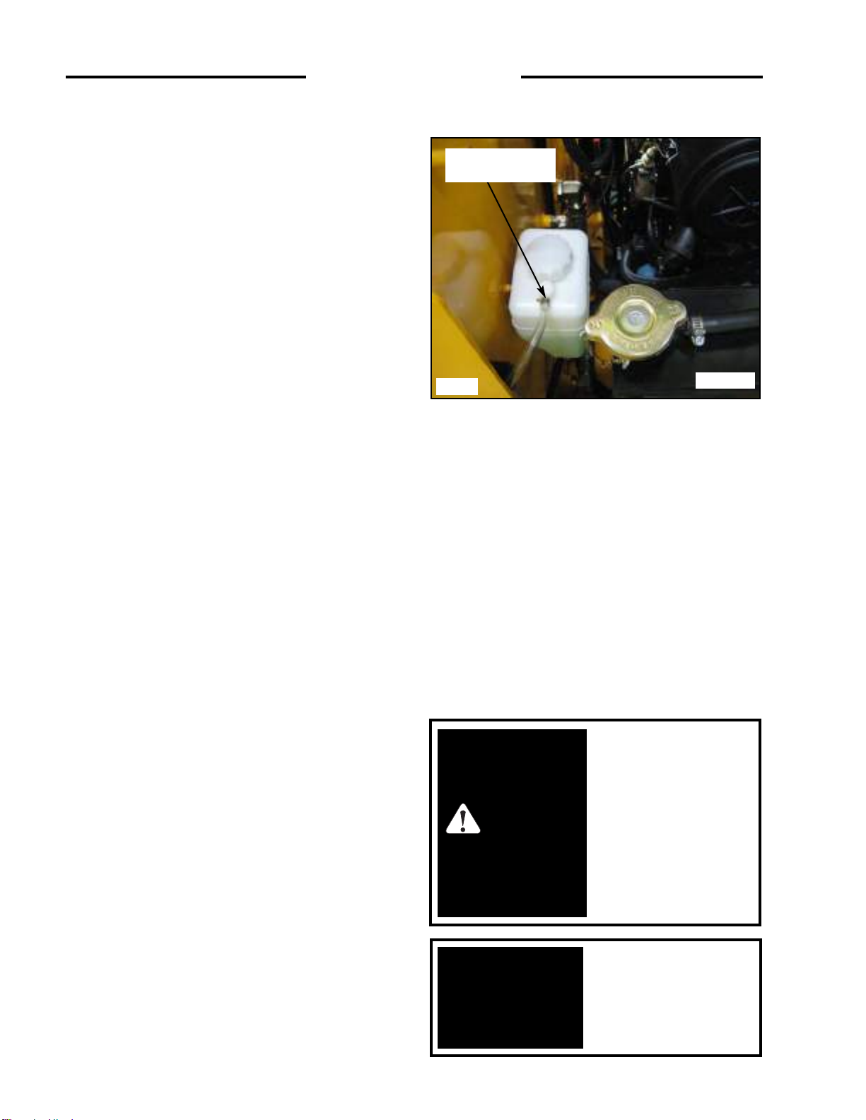
8. Radiator / Oil Cooler Service
With the engine cool, check the coolant level in the
overflow reservoir (fig. 4.3G). Ensure the coolant level is
at the Full-Cold mark on the reservoir by adding 50%
mixture of ethylene glycol and water if required.
The radiator and oil cooler fins must be kept free of debris
otherwise overheating of the engine will occur. Inspect the
radiator cooling fins for damage or buildup of debris.
Repair any damage and if necessary flush the radiator
with compressed air to remove debris.
4. 4 50 HOUR SERVICE CHECK
The following service check is to be performed by your
dealer after the first 50 hours of operation.
1 Engine
1.1 Oil and Filter:
Change the engine oil and filter. Use only original
replacement parts. Change the oil every 200 hours
thereafter. Change the filter every 200 hours
thereafter.
1.2 Radiator:
Check the coolant level. If necessary flush the radiator
with compressed air. A dirt buildup on the radiator
cooling fins can cause both engine and hydraulic
system overheating.
1.3 Fan Drive:
Inspect fan, bolts, v-belt and guard to ensure there is
no buildup of dirt, trash, or wear. Use compressed air
to clean the area.
1.4 Fuel System for Leaks:
Make a visual inspection of fuel system for leaks and
potential hazards such as fuel line(s) touching exhaust
manifold, flywheel, etc. Replace fuel filter every 300
hours.
1.5 Air Intake and Cleaner System:
Visually inspect the air cleaner system and be sure all
hose clamps are secure and no hoses are damaged.
1.6 Exhaust System:
Visually inspect the exhaust system and ensure all
clamps are secure and the manifold bolts/nuts are tight.
1.7 Engine Speed:
Check, and if necessary adjust engine RPM.
4. MAINTENANCE
Keep the rear door
closed except for
servicing. Make sure the
door is closed and
latched before operating
the loader.
IMPORTANT
To avoid personal injury,
lower the lift arms, shut off
the engine, raise the seat bar
and cycle the hydraulics to
ensure they are locked. Then,
unlatch the seat belt and exit
the loader. Do not enter or
exit with the engine running
unless as specified in this
manual or under specific
service and backhoe
operating procedures.
WARNING
Coolant Overflow
Reservoir
C1663
Fig. 4.3G

37
2 Hydraulic/Hydrostatic
2.1 Hydraulic Oil Filter:
Change the hydraulic filter now and every 200 hours
after the initial change. Lubricate the filter cartridge
seal with system fluid.
2. 2 Hydraulic Oil Level:
If oil is visible in the oil level sight glass the level
satisfactory. If not add oil.
2.3 Hoses and Pipes:
Make a visual inspection of all hydraulic lines and
fittings for leaks. Check that steel lines do not touch
one another.
2.4 Cylinders:
Inspect cylinders for leaks. Extend cylinders and
check for rod damage.
2.5 Hydraulic Functions:
Check that the following operate properly: control
valve float position, auxiliary hydraulic and hydraulic
cylinders.
2.6 Pumps, Motors, and Controls Leakage:
Inspect pumps and motors for leaks.
2.7 Oil Cooler:
Inspect the oil cooler for leaks, fin damage or clogged
with dirt. If necessary flush fins with compressed air.
3 Final Drive
3.1 Oil Level:
Check lubricating oil level. If necessary add oil.
3.2 Drive Chain Condition:
Check drive chains for any sign of wear or damage.
Check lubrication oil in housing for signs of
contamination.
3.3 Hydrostatic Motor Mounting Bolts:
Check torque 85 - 90 ft. lbs. (115 - 122 Nm)
3.4 Bearing End Play:
Check axle bearings for loss of bearing pre-load. If
necessary, adjust the bearings for zero end play.
3.5 Axle Seal:
Inspect axle seal area. Clean area of debris build up
and visually check for seal damage, replace as
required.
4 Controls and Safety Equipment
Seat Bar Switch Check: Raise the seat bar and check that the
hydraulic controls are not functional.
Seat Belt Switch Check: Unbuckle the seat belt and check
that the hydraulic controls are not functional.
Seat Switch Check: With the seat bar down and the seat belt
connected loosely around you, raise your weight off
the seat and check that the hydraulic controls are not
functional.
4.1 Engine Throttle Control:
Check that the throttle control operates freely without
binding or slackening off due to vibration.
4. 2 Parking Brake:
Check that the parking brake engages and completely
disengages. The park brake automatically engages with
seat bar up.
4. 3 Lift Arm Supports:
Check that the lift arm support will operate without
binding.
4.4 Quick-Tach, Operation & Linkage:
Ensure the quick-tach linkage operates smoothly
without binding and engage completely.
4.5 Seat Belt:
Check seat belt condition. If necessary replace.
4. MAINTENANCE
To avoid personal injury:
never repair or tighten
hydraulic hoses or
fittings with the engine
running or the system
under pressure.
WARNING

38
5 Electrical
5.1 Battery (s):
Maintenance Free.
5.2 Battery Terminals:
Check battery terminals for corrosion. If necessary,
clean.
5.3 Starter Operation:
Engage and disengage the starter a few times to ensure
it•s working properly. To prevent starter damage do not
engage for more than 15 seconds. Allow 1 minute
between starting attempts for cooling the starter.
5.4 Operation of Electrical Equipment:
Make a complete check of all electrical equipment,
gauges, warning devices, pre- heater indicator, work
lights, seat and seat belt switch, seat bar switch and all
optional equipment to ensure they are operating
correctly.
6 Grease/Lubrication
Lubricate the following points with a good quality
grease every 8 hours. Numbers marked ( ) indicate the
number of fittings at each location.
Rear Lift Arm Pivots (2)
Lift Arm Cylinder Bushings (4)
Bucket Cylinder Bushings (4)
Quick - Tach Pivot (4)
7 General
7. 1 Tire Pressure:
Check tire pressure and if necessary inflate to the
following pressures:
10.00 x 16.5 . . . . . . . 40 - 45 PSI (207 - 241 kPa)
7. 2 Wheel Nut Torque:
Check and torque wheel nuts to 100 - 110 ft. lbs. (136
- 149 Nm).
7.3 Condition of Cab:
Inspect both the seat and seat belt. Ensure all safety and
instruction decals are in place. Inspect sound
insulation, side windows and door operation for
machines equipped with cab enclosure kits. Inspect for
structural damage and alterations to R.O.P.S.
7. 4 Condition of Shields and Safety Equipment:
Inspect and ensure all shields are in place and
securely fastened. Inspect and ensure all safety
equipment is working properly. Ensure owners and
operators manual,
safety manual and all safety and
instruction decals are in place. If necessary, replace.
7. 5 General Condition:
Make a general inspection of the machine looking for
loose or missing parts, oil leaks, etc.
4. 5 200 HOUR SERVICE CHECK
Initial 200 hour check should be performed by an
authorized dealer.
1. It is recommended that the 50 hour check (see
Section 4.4) be repeated at 200 hours.
4. MAINTENANCE

39
4. 6 FINAL DRIVE MAINTENANCE
1. Oil Level Check
The loader has two independent final drive housings.
Check the lubricating oil level with the loader on a level
surface. Remove the check plug (Fig. 4.6A) located on the
front of the loader to determine the oil level. The oil level
should be checked after 50 operating hours and every 200
hours thereafter. It is recommended the oil be changed
after 1000 operating hours or if it shows signs of
contamination.
2. Adding Oil
Add oil with the loader on level ground. Remove the oil
level check plug (Fig. 4.6A) on the final drive housing.
Raise cab (Section 4.2) and remove the front foot shields.
Remove the filler cap (Fig. 4.6B & Fig. 4.6C). Fill to the
level of the check plug. (Fig. 4.6A)
3. Drive Chain, Axle and Sprocket Inspection
The condition of the drive chains should be checked after
the first 50 hours of operation and every 200 hours
thereafter.
To inspect, block the loader securely with all four wheels
off the ground. Remove both the front and rear wheels. On
reassembly torque the wheel nuts to 100-110 ft. lbs. (136149 N m). Remove the inspection cover on the side of the
chain drive housing.
Inspect the chain for any sign of wear, damage or
excessive looseness. Inspect the sprockets for any sign of
damage or excessive wear. Inspect the lubricating oil for
signs of contamination. Check the axle bearings for loss of
bearing preload. If necessary adjust the bearings for zero
end play.
Check the axle seals for leaking oil or damage. Replace
seals at first sign of problem.
4. MAINTENANCE
Fig. 4.6A
C5276
Filler Cap
Fig. 4.6B
C5268
C5269
Fig. 4.6C
Filler Cap
Check Plugs

40
4. 7 HYDRAULIC/ HYDROSTATIC
SYSTEM MAINTENANCE
1. Oil Level Check
Check the oil level of the hydraulic reservoir with the
machine on a level surface with the lift arms down and
the attachment grounded. Shut off the engine. Open the
rear door and check the oil level sight glass (Fig. 4.7A).
If oil is apparent the level is satisfactory.
WARNING
WARNING: Escaping hydraulic
fluid under pressure can
penetrate the skin causing
serious injury.
.DO NOT use your hand to check
for leaks. Use a piece of cardboard
or paper to search for leaks.
. S top engine and relieve pressure
before connecting or disconnecting
lines.
. Tighten all connections before
starting engine or pressurizing
lines.
If any fluid is injected into the skin
obtain medical attention
immediately of gangrene may
result.
4. MAINTENANCE
C5262
Oil Level
Sight tube
Fig. 4.7A

41
2. Adding Oil
To add oil, remove the oil filler cap located at the top of the
oil reservoir (Fig. 4.7B). Check and ensure the filter screen
in the filler neck is undamaged. Add ISO VG32 oil until oil
is visible in the oil level sight glass (Fig. 4.7A).
3. Hydraulic Filter Replacement
The hydraulic oil filter (Fig. 4.7C) must be changed after
the first 50 hours of operation and every 200 hours
thereafter.
To change the filter; shut off the engine, lower the lift
arms, ground any attachment and set the parking brake.
Open the rear door and using an oil filter wrench remove
the filter element. Lubricate the new filter seal with
system fluid and reinstall hand tight.
4. Draining System Fluid
Change the hydraulic oil:
1. After 1000 operating hours.
2. If the oil has become contaminated.
3. After any major hydrostatic repair.
To drain the oil: remove the drain plug located at the
bottom of the reservoir (Fig. 4.7D). Have a container(s)
ready to hold approximately 20 gallons (76 liters) of
fluid. Remove any metal particles stuck to the magnet.
Seal the plug with teflon tape when replacing.
4. MAINTENANCE
To avoid personal injury,
lower the lift arms, shut off
the engine, raise the seat bar
and cycle the hydraulics to
ensure they are locked. Then,
unlatch the seat belt and exit
the loader. Do not enter or
exit with the engine running
unless as specified in this
manual or under specific
service and backhoe
operating procedures.
WARNING
Fig. 4.7B
Fig. 4.7D
C5263
C5252
SUNBEAR recommends
that you abide by all
applicable enviromental
regulations when
disposing of oil.
IMPORTANT
OIL FILLER CAP
C5252
Fig. 4.7C
Hydraulic Filter
OIL RESERVOIR
DRAIN

5. Oil Cooler and Cooling Fan
Oil returning from the control valve is circulated through
the oil cooler before being sent to other parts of the
hydraulic system.
An engine cooling fan drives air through the oil cooler.
Refer to Figure 4.7E.
The oil cooler should be checked daily for dirt buildup on
the cooling fins. If the air flow is restricted through the
cooling fins, overheating of the hydraulic system may
occur. Clean any dirt buildup with compressed air. Flush
with water if necessary. Figure 4.7E shows the
radiator/oil cooler setup for the loader.
6. Brake Service Override
A service override has been incorporated for use by
SUNBEAR Dealers.
The normal position of the plunger
is down and turned into the locked position (Fig. 4.7F).
To release the park brake, turn the release button counter
-clockwise (Fig.4.7F). Go to the rear of the machine and
pressurize the small quick coupler to 200 psi to release the
park brake (Fig. 4.7G).
4. MAINTENANCE
Fig. 4.7E
C5319
Fan
To avoid eye injury
always use safety goggles
when cleaning with
compressed air.
WARNING
Fig. 4.7F
C5260
42
C5259
Fig. 4.7G
Brake Quick
Coupler
Brake Release Valve
Oil Cooler
Plungers

43
2. Oil Level Check
Check the oil before engine start up. If the engine has been
running let it cool for at least 5 minutes.
To check the oil level, stop the engine with the loader on
level ground, open the rear door and remove the dipstick
(Fig. 4.8A).
Keep the oil level between the full and low mark on the
dipstick. Do not fill above the full mark.
3. Engine Oil and Filter Replacement
Operate the engine until warm, approximately 5 minutes.
Stop the engine. Remove the oil drain plug located at the
bottom of the oil pan. Remove the oil filter (Fig. 4.8B).
Clean the filter housing surface. Put clean oil on the seal of
the new filter and install the filter hand tight.
Replace the oil drain plug. Remove the filler cap and add
engine oil. Start the engine and run for 5 minutes. Stop the
engine and check for leaks at the filter. Recheck the oil
level and add oil until the level is at the top mark on the
dipstick. Check daily and change every 200 hours.
WARNING
To avoid personal injury:
Stop, Cool and Clean the
engine of flammable
materials before
servicing. Never service
or adjust machine with
engine running.
4. MAINTENANCE
C5267
Fig. 4.8A
C5323
Fig. 4.8B
Engine Oil
Filter
SUNBEAR recommends
that you abide by all
applicable enviromental
regulations when
disposing of oil.
IMPORTANT
4. 8 ENGINE MAINTENANCE
1. Engine Specification
Make............................................................................................Cummins
Model...........................................................................................A2300T
No. of Cyls ..................................................................................4
Horsepower (Gross) ................................................................ 60
Power (ISO9249 Net Power) ......................................................44.7kW
High Idle............................................................................. ........2800
Max. Torque ................................................................................135(18.7kg/m@ 1600)
Displacement...................................................................... ........139cid(2290cc)
Engine Oil ...................................................................................7.5 US qts.(7 L)
Firing Order.................................................................................1-3-4-2
Alternator.....................................................................................45A
Oil Check.....................................................................................Daily
Oil Change..........................................................................First@50 hrs.........Second@200 hrs.
Filter Change......................................................................First@50 hrs.........Second@200 hrs
Dipstick
Location

44
4. V-Belt Tension
Check the V-belt tension midway between the crankshaft
pulley and alternator pulley (Fig. 4.8C). Deflection should
be between 1/4 to 3/8 in. (7-9 mm).
5. Adding Fuel
Use No. 2 diesel fuel only. Total tank capacity 20 gal.
(76L). Before adding fuel to the loader the key switch
must be off and the engine must be cool. Remove the fuel
cap (Fig. 4.8D). Use a clean approved safety container to
add fuel. Add fuel only in an area that is well ventilated
and away from open flames or sparks - NO SMOKING!
6. Fuel Filter /Water Separator
The fuel filter/water separator is located in the engine
compartment on the right hand side (Fig. 4.8F). The fuel
filter/water separator should be drained of water daily.
SHUT OFF ENGINE
Drain the water-fuel separator into a container and dispose
of in accordance with local enviormental regulations. To
drain, turn the drain valve (Fig.4.8G) on bottom of filter
counterclockwise approximately 3-1/2 turns until the valve
drops down 1" and draining occurs. Drain the filter sump
until clear fuel is visible. To close the valve, lift the valve
and turn clockwise until it is hand tight.
To replace the filter close the fuel inlet line shut - of f
located on the side of the fuel tank (Fig. 4.8E). Remove the
filter element (Fig. 4.8F). Lubricate the seal on the new
filter and install the filter hand tight. Open the fuel inlet
shut - off. It may be necessary to remove air from the fuel
system after changing the filter element. (Refer to Section
4.8-7).
Fig 4.8E
Fuel Inlet Shut - off
Fig. 4.8F
C5265
4. MAINTENANCE
Alternator
Pulley
Fan Pulley
Crankshaft Pulley
Fig. 4.8C
C-5321
Fuel Cap
C5258
Fig.4.8D
To avoid personal injury
never add fuel to the
loader when the engine is
running or is hot. NO
SMOKING.
Fuel Filter
C5423
Fig. 4.8G
Drain Valve
C5257
WARNING

7. Bleeding the Fuel System
Air must be removed from the fuel lines, after replacement of
the fuel filter element, or when the tank has been run out of
fuel, before starting the engine.
T o remove air , ensure the fuel inlet shut-of f located on the side
of the fuel tank is open (Pg. 43, Fig. 4.8E). Open the air bleed
screw on fuel filter head by turning it counter clockwise (Fig.
4.8H) . Operate the priming pump plunger until the fuel
flowing from the bleed screw is free of air. Close the air bleed
screw on the fuel filter head.
Bleed Low Pressure Fuel Lines
Note: Use this procedure only if the air bleed screw fails
to remove air from the system.
Open fuel return line bleed screw on the pump (Fig. 4.8I).
Hold the banjo bolt with a wrench while using a second
wrench to open bleed screw.
Operate the plunger on the fuel filter head until the fuel
flowing from the bleed screw is free of air.
Tighten the fuel return line bleed screw on the fuel pump
using one wrench to hold banjo bolt while tightening the bleed
screw with a second wrench.
Air Bleed Screw
Plunger
Push Down
C5354 Fig. 4.8H
Drain Valve
Bleed Screw
C5424
C5366
Fig.4.8J
Fuel Droplets
Fig. 4.8I
4. MAINTENANCE
45

4. 9 AIR CLEANER MAINTENANCE
1. Daily Maintenance
Inspect the air cleaner canister for holes, dents,
missing or mis-aligned gaskets. Check all hose
clamps for tightness and inspect the hose and
vacuator valve for damage (Fig. 4.9A).
2. Servicing Cleaner Element (Fig. 4.9B)
DO NOT open unless the indicator indicates a blocked
filter or under normal scheduled servicing. To check
the indicator, with the engine running, block half of the
intake inlet and check the indicator on the dash panel.
It should illuminate to simulate a blocked filter.
2.1 Unlatch and remove the cover assembly
2.2 Release The Seal Gently - The filter should be
removed gently to reduce the amount of dust
dislodged. Move the end of the filter up and down
and side to side or twist to break the seal.
2.3 Avoid Dislodging Dust From The Filter - Gently
pull the filter off the outlet tube. Avoid knocking
the filter against the housing.
2.4 Always Clean The Sealing Surface Of The Outlet
Tube - Dust on the outside diameter of the housing
could hinder an effective seal.
2.5 Always Clean The Inside Of The Outlet Tube - Dirt
inside of the outlet tube will reach the engine : it
only takes 9 grams of dirt to dust an engine.
2.6 Check Your Old Filter - Inspecting your old filter
will detect foreign material on the sealing surface
that may causing leakage.
2.7 Inspect the new filter for seal or pleat damage.
2.8 Insert the new filter properly - The seal area is on
the inside of the open end of the primary filter. A
new filter has a dry lubricant to aid installation. The
critical sealing area will stretch slightly, adjust
itself and distribute the sealing pressure evenly. To
complete a tight seal, apply pressure at the outer
rim of the filter, not the flexible centre. No cover
pressure is required to hold the seal.
2.9 Check connections and ducts for air tight fit - Make
sure all clamps, bolts and connections are tight.
Check for holes in piping. Leaks here send dust
directly to the engine.
2.10 DO NOT reuse filters.
4. MAINTENANCE
To avoid personal injury,
lower the lift arms, shut off
the engine, raise the seat bar
and cycle the hydraulics to
ensure they are locked. Then,
unlatch the seat belt and exit
the loader. Do not enter or
exit with the engine running
unless as specified in this
manual or under specific
service and backhoe
operating procedures.
WARNING
To avoid personal
injury: DO NOT charge
a frozen battery because
it can explode and cause
personal injury. Let the
battery warm to
60°F.(15.5°C.) before
putting on a charger.
WARNING
Inlet
Outlet
Cover Assembly
Vacuator
Valve
Latch
Safety
Filter
Primary
Filter
C-653
Fig. 4.9B
46
Fig 4.9A
C5277
Air Cleaner
Hose
Vacuator Valve

4. 10 ENGINE COOLING SYSTEM
The engine cooling system fluid is a 50-50 mixture of
ethylene glycol anti-freeze and water for both coldweather protection and boil over protection.
To drain the cooling system; locate the rad drain valve on
the front right side of the radiator (Fig. 4.10B & 4.10C).
Use the attached hose to direct coolant into an appropriate
container and open valve to drain radiator.
To completely drain the engine, undo clamp and remove
cap from the engine drain nipple located on the engine oil
cooler (Fig. 4.10A) and attach a hose to drain coolant into
a container. Remove the radiator cap.
To fill the cooling system; re-cap and clamp the drain
nipple on the engine oil cooler (Fig. 4.10A) and close the
radiator drain valve (Fig. 4.10B & 4.10C). Fill the radiator
with a 50-50 mixture of ethylene glycol anti-freeze and
water. Refit the radiator cap. (Fig. 4.10D)
C5370
Fig. 4.10A
WARNING
To avoid personal injury:
DO NOT remove the
radiator cap when the
engine is hot.
4. MAINTENANCE
47
Engine Coolant
Drain
Engine
OilCooler
C5378
Fig. 4.10B
WARNING
To avoid personal injury
never add coolant when
the engine is running or
is hot.
C5358
Percentage Ethylene Glycol
Freeze Temp.
Boil Temp.
Rad Cap
C5419
Fig. 4.10C
50
41
32
23
14
5
-4
-13
-22
-31
-40
-49
-58
-67
-76
-85
-94
-103
0 10 20 30 40 50 60 70 80 90 100
Freezing
Point
Boiling
Point
329
320
311
302
293
284
275
266
257
248
239
230
221
212
203
194
185
176
Drain Valve

48
4. 11 ELECTRICAL SYSTEM
1. Battery Maintenance and Boosting
Inspect the batteries on a regular basis for damage such as
a cracked or broken case or cover which would allow
electrolyte loss.
Check the battery cables for tightness and corrosion.
Remove any acid corrosion from the battery and cables
with a baking soda and water solution. Coat the terminal
connections with di-electric grease.
If it is necessary to use a booster battery to start the engine,
BE CAREFUL! There must be one person in the operators
seat and one person to connect and disconnect the battery
cables.
4. MAINTENANCE
WARNING
To prevent personal injury
DO NOT charge a frozen
battery because it can
explode and cause
personal injury. Let the
battery warm to 60
°
F.
(15.5°C.) before putting on
a charger.
Lead-acid batteries contain
sulfuric acid which will
damage the eyes or skin on
contact. Always wear goggles
to avoid acid in the eyes. If
acid contacts the eyes, wash
immediately with LARGE
QUANTITIES of clean water
and get medical attention.
Wear rubber gloves and
protective clothing to keep
acid off the skin. If acid
contacts the skin, wash off
immediately with clean water.
WARNING

49
2. ELECTRICAL SCHEMATIC, 1 OF 3
4. MAINTENANCE

50
2. ELECTRICAL SCHEMATIC, 2 OF 3
4. MAINTENANCE

4. MAINTENANCE
51
2. ELECTRICAL SCHEMATIC, 3 OF 3
20
A M M CS R R L T L L L A/C
22
29
28
23
3 4 19 18 24 10 25 27 26 17
(A) (B)
S S S S S S
1. Starter
4. Glow plug
7. Engine Oil Pressure Indicator
10. Fuel Level Sender
13. Control Valve Solenoid (A)
16. Backup Alarm
19. Starter Relay
22. Iginition S/W
25. Work Light (Rear)
28. S/W for the Wiper Motor
31. Restraint Bar S/W
12
L L L L L
32
33
31
HORN
13 14 15 16 12 11 6 7 8 9
▣ INDEX (ELECTRICAL SCHEMATIC) ▣
AL
2. Alternator
5. Engine Shut-off Solenoid
8. Coolant Temp. Sender
11. Brake Valve Solenoid (Left)
14. Control Valve Solenoid (B)
17. Cigar Jack
20. Circuit Breaker (40A)
23. Fuel Gauge
26. Work Light (Front, High)
29. Toggle S/W for the Work Lights
32. Seat S/W
L
3. Battery
6. Air Filter Service Indicator
9. Hyd. Oil Temp. Sender
12. Brake Valve Solenoid (Right)
15. Horn
18 Pre-heater Relay
21. Fuse Box
24. Hour Meter
27. Work Light (Front, Low)
30. Push Button S/W for the Aux.
33. Seat Belt S/W

4. 12 TIRE MAINTENANCE
1. Tire Inflation and Service
1.1 Upon receiving your loader, check the air pressure
in the tires as indicated in the tables.
1.2 Check tire pressure every 8 hours.
1.3 Tire inflation pressure affects the amount of
weight which a tire may carry. Do not over-orunder inflate the tires.
1.4 Do not re-inflate a tire that has been run flat or
seriously under-inflated until the tire has been
inspected for damage by a qualified person.
1.5 When checking tire pressure, inspect the tire for
damaged side walls and tread cuts. Neglected
damage will lead to early tire failure.
1.6 Be sure the rim is clean and free of rust.
1.7 Lubricate both tire beads and rim flanges with
soap solution. Do not use oil or grease.
1.8 Use a clip-on tire chuck with a remote hose and
gauge which allows the operator to stand clear of
the tire while inflating it.
1.9 After seating the beads, adjust inflation pressure to
recommended operating pressure.
1.10 Do not inflate a tire unless the rim is mounted on
the loader or is secured so that it will not move if
the tire or rim should suddenly fail.
1.11 Do not weld, braze, or otherwise repair a rim, Do
not use a damaged rim.
1.12 Never attempt tire repairs on a public road or
highway.
1.13 Use jack stands or other suitable blocking to
support the loader while repairing tires
1.14 Insure jack has adequate capacity to lift your
loader.
1.15 Insure jack is placed on a firm level surface.
1.16 Do not put any part of your body under the loader
or start the engine while the loader is on the jack.
1.17 Torque lug nuts to specification after reinstalling
wheel. Check lug nut torque hourly until torque
stabilizes.
10.00 x 16.5 40-45 PSI (276 - 310 kPa)
2. Tire Rotation
The front and rear tires will wear at different rates. For
even wear move the front tires to the rear and the rear tires
to the front when wear is first noticed.
If two tires become worn more than the other two put the
two worn tires on the same side.
When new tires are installed, always keep tires the same
size on the same side of the loader. Two different size tires
on the same side of the loader will cause drive chain wear,
tire wear and a loss of power
.
WARNING
To avoid personal injury:
Inflating or servicing
tires can be dangerous.
Trained personnel should
be called to service
and/or mount tires when
possible. In any event to
avoid possible serious or
fatal injury, follow the
safety precautions below.
4. MAINTENANCE
52
WARNING
NEVER INFLATE
TIRES TO OVER 240
kPa (35 PSI) TO SEAT
BEADS. If beads have not
seated by the time
pressure reaches 240 kPa
(35 PSI), deflate the
assembly, reposition the
tire on the rim,
relubricate both tire
beads, rim flanges and re-
inflate. INFLATION
Beyond 240 kPa (35 PSI)
with unseated beads may
break the bead or rim
with EXPLOSIVE force,
sufficient to cause serious
injury.
TIRE Inflation Pressure

53
4. MAINTENANCE
4. 13 TROUBLESHOOTING
1. Hydraulic System
Problem Cause Remedy
Loss of hydraulic power (no flow
from gear pump)
Loss of hydraulic power (flow from
gear pump)
Hydraulic action jerky
Hydraulic System Overheating
Lift arms raise slowly at full engine
RPM
Lift or tilt cylinders will not support
a load
Hydraulic fluid overheating
Reservoir low on fluid.
Coupling between engine and pump
failure.
Spline coupling failure between front
and rear hydrostatic pump.
Hydraulic gear pump not functioning.
Reservoir low on fluid.
Auxiliary hydraulics engaged.
Relief valve failure in control valve.
Reservoir low on oil.
Air in hydraulic system.
Anticavitation check valve not
functioning.
Engine fan not turning.
Broken hydraulic fluid line.
Reservoir low on oil.
Liftarm release valve engaged.
Auxiliary engaged.
Engine RPM too slow.
Anticavitation check valve spring
broken.
Main relief or port relief valve in
control valve faulty.
Internal leakage in pump due to wear.
Oil bypassing one or both lift cylinder
piston seals.
External leak between or at control
valve and cylinders.
Control valve spool not centering.
Oil leaking by one or both cylinder
piston seals.
Reservoir low on fluid.
Oil cooler plugged or dirty (also
check engine radiator).
Auxiliary engaged.
Add oil and check for leaks.
Inspect and replace damaged parts.
Check for misalignment between
engine and pumps.
Inspect coupling for sheared splines.
Also check pump shaft bearings.
Inspect and repair.
Add oil and check for leaks.
Release auxiliary hydraulics.
Check pressure and adjust.
Add oil and check for leaks.
Check for leak between reservoir
and pump. Bleed system by
extending and retracting lift
cylinders several times.
Inspect and repair or replace.
Clean cooling fan and repair or
replace.
Repair or replace damaged line and
add oil.
Add oil.
Ensure switch is off, valve is closed.
Disengage.
Check RPM and reset.
Replace.
Check pressure, if necessary - adjust.
Check pump flow and repair or
replace as necessary.
Install new piston seal kits.
Check for leaks and correct.
Pilot hydaulic pressures not even.
Check for broken or stuck return
spring on valve spool.
Install new piston seal kits.
Add oil.
Clean cooling fins.
Disengage.

54
4. MAINTENANCE
1. Hydraulic System (Continued)
Problem Cause Remedy
Hydraulic fluid overheating
(continued)
Auxiliary hydraulic does not
function.
Engine RPM too slow
Incorrect temperature sensor
Fuse blown.
Solenoid coils on control valve not
working.
Check valve in control valve not
working.
Check RPM and adjust.
Replace.
Correct fault and replace fuse.
Replace
Repair or replace.
2. Hydrostatic Drive
Problem Cause Remedy
No power on one side (both
directions).
No power on one side (one direction
only).
No power on both sides (also loss of
hydraulic power).
Gradual loss of power as machine
warms up.
System erratic and/or noisy.
Machine will not travel in a straight
line.
Reservoir low on oil.
Pilot hydraulic line failure.
High pressure line failure.
Drive chain failure.
Motor shaft or key failure.
Excessive internal leakage in motor
and/or pump.
Defective relief valve.
Pilot hydraulic line failure.
Reservoir low on oil.
Coupling failure between engine and
pump.
Brake valve not releasing.
Drive coupling between front and
rear pump failure.
Check system pressure.
Excessive internal leakage in pump
and/or motor.
Air in system due to low oil level in
reservoir.
Air in system due to leak at suction
fitting.
Internal pump or motor wear caused
by overspeeding.
Air in system due to leak at oil
reservoir.
Pressure failure in hydraulic pump.
Add oil and check for hose or fitting
leak.
Replace line.
Replace line. Ensure new line fits
without being forced. If necessary
stress relieve.
Replace chain or connection link.
Inspect and repair defective parts.
Check motor mounting bolts.
Inspect and repair defective unit.
Flush all lines and tank. Replace
filter. Check on type of fluid used
and engine RPM.
Replace defective valve.
Replace line.
Add oil and check for hose or fitting
leak.
Inspect and replace damaged parts.
Repair/replace.
Inspect couplings for sheared
splines, replace. Also check support
bearings in pumps.
If low contact your
Consult your Thomas
Bleed air from the system and add
oil.
Check fittings and tighten.
Consult your dealer.SUNBEAR
Check fitting and tighten.
Check and adjust.
dealer.
SUNBEAR dealer.
SUNBEAR

55
4. MAINTENANCE
4. Control Levers
Problem Cause Remedy
Control levers will not center.
Machine operates erratically.
Machine will not travel in a straight
line.
Joystick will not center.
Pilot hydraulic line leaking.
Failure in hydraulic line.
Pilot hydraulic line leaking.
Adjust or replace.
Replace hydraulic line.
Check and repair.
Replace hydraulic line.
3. Final Drive Transmission
Problem Cause Remedy
Final drive transmission noisy
No lubricating oil
Axles have too much end play
Parking brake damaged or out af
adjustment
Chain loose
Check and bring oil to the proper
level.
Check and adjust.
Inspect and adjust or replace
damaged parts.
Replace the chain.
5. Electrical
Problem Cause Remedy
Engine will not crank over.
Battery failure.
Battery cable failure.
Starter failure.
Fuse burnt.
Defective relay.
Ignition switch failure.
Check battery - charge or replace.
Check for loose or corroded
connectors. Tighten and clean as
required. Use di-electric grease to
prevent corrosion.
Check continuity of cables and
replace.
Repair or replace.
Check and replace.
Check relay continuity. If defective,
replace.
Check continuity, repair or replace.

56
5. Electrical (Continued)
Problem Cause Remedy
Engine cranks over, but will not
start.
Loader starts, but hydraulic controls
will not release.
Auxiliary hydraulics engaged
Defective glow plug relay.
Defective glow plug.
Broken connection or defective wire.
No fuel.
Electric solenoids not releasing
valve.
Engine will smoke, but not run
unassisted by starter. Disengage
auxiliary hydraulics.
Check continuity and if defective,
replace.
Check continuity and if defective,
replace.
Disconnect the ROPS harness from
the engine harness. Open the dash
panel and check continuity of the
circuit not functioning properly in
both engine and ROPS harness.
Check fuel levels and system.
Defective solenoid or solenoid lock.
Loosen screws and readjust. Check
continuity of connectors and wire.
4. MAINTENANCE
6. Engine
Problem Cause Remedy
Engine does not start.
No fuel.
Air in the fuel.
Water in the fuel.
Fuel pipe clogged.
Fuel filter clogged.
Excessively high viscosity of fuel or
engine oil at low temperature.
Fuel with low octane number.
Fuel leak due to loose injection pipe
retaining nut.
Incorrect injection timing.
Fuel cam shaft worn.
Injection nozzle clogged.
Injection pump malfunctioning.
Seizure of crankshaft, camshaft,
piston, cylinder liner or bearing.
Compression leak from cylinder.
Improper valve timing.
Piston ring and liner worn.
Excessive valve clearance.
Replenish fuel.
Vent air.
Change fuel and repair or replace
fuel system.
Clean.
Clean or change.
Use the specified fuel or engine oil.
Use the specified fuel.
Tighten nut.
Adjust.
Replace.
Clean.
Repair or replace.
Repair or replace.
Replace head gasket, tighten cylinder
head bolt, glow plug and nozzle
holder.
Correct or replace timing gear.
Replace.
Adjust.

57
4. MAINTENANCE
6. Engine (Continued)
Problem Cause Remedy
Starter does not run.
Engine revolution is not smooth.
Either white or blue exhaust gas is
observed.
Either black or dark gray exhaust gas
is observed.
Excessive lubricant oil consumption.
Fuel mixed into lubricant oil.
Water mixed into lubricant oil.
Low oil pressure.
High oil pressure.
Battery discharged.
Starter malfunctioning.
Key switch malfunctioning.
Wiring disconnected.
Fuel filter clogged or dirty.
Air cleaner clogged.
Fuel leak due to loose injection pipe
retaining nut.
Injection pump malfunctioning.
Incorrect nozzle opening pressure.
Injection nozzle stuck or clogged.
Fuel overflow pipe clogged.
Governor malfunctioning.
Excessive engine oil.
Low grade fuel used.
Fuel filter clogged.
Air cleaner clogged.
Overload.
Low grade fuel used.
Fuel filter clogged.
Air cleaner clogged.
Piston rings gap facing the same
direction.
Oil ring worn or stuck.
Piston ring groove worn.
Valve stem and guide worn.
Crankshaft bearing and crank pin
bearing worn.
s plunger worn.Injection pump'
Injection pump broken.
Head gasket defective.
Cylinder block or cylinder head
flawed.
Engine oil insufficient.
Oil strainer clogged.
Relief valve stuck with dirt.
Relief valve spring weakened or
broken.
Excessive oil clearance of crankshaft
bearing.
Excessive oil clearance of crank pin
bearing.
Excessive oil clearance of rocker
arm bearing.
Oil passage clogged.
Oil pump defective.
Different type of oil.
Relief valve defective.
Charge.
Repair or replace.
Repair or replace.
Connect.
Clean or change.
Clean or change.
Tighten nut.
Repair or replace.
Adjust.
Repair or replace.
Clean.
Repair.
Reduce to the specified level.
Repair or replace.
Adjust.
Adjust top clearance.
Lessen the load.
Use the specified fuel.
Clean or change.
Clean or change.
Shift gap direction.
Replace.
Replace.
Replace.
Replace.
Replace pump element or pump.
Replace.
Replace.
Replace.
Replenish.
Clean.
Clean.
Replace.
Replace.
Replace.
Replace.
Clean.
Replace.
Use the specified oil type.
Replace.

6. Engine (Continued)
Problem Cause Remedy
Engine overheated.
Deficient output.
Battery quickly discharges.
Engine oil insufficient.
Fan belt broken or elongated.
Cooling water insufficient.
Radiator net and radiator fin clogged
with dust.
Inside of radiator corroded.
Cooling water flow route corroded.
Radiator cap defective.
Overload running.
Head gasket defective.
Incorrect injection timing.
Unsuitable fuel used.
Incorrect injection timing.
Engine' s moving parts seem to be
seizing.
Uneven fuel injection.
Deficient nozzle injection.
Compression leak.
Battery electrolyte insufficient.
Fan belt slips.
Wiring disconnected.
Rectifier defective.
Alternator defective.
Battery defective.
Replenish.
Change or adjust.
Replenish.
Clean.
Clean or replace.
Clean or replace.
Replace.
Loosen the load.
Replace.
Adjust.
Use the specified fuel.
Adjust.
Repair or replace.
Repair or replace injection pump.
Repair or replace nozzle.
Replace head gasket, tighten cylinder
head bolt, glow plug and nozzle
holder.
Replenish distilled water recharge.
Adjust belt tension or charge.
Connect.
Replace.
Replace.
Change.
4. MAINTENANCE
58

1
P
D
2
3
D
P
1
3
D
2
P
4. MAINTENANCE
4.14 HYDRAULIC / HYDROSTATIC CIRCUIT
Oil Cooler
Return From
Liftarm Lowering
Valve
Hydraulic Gear
Control Valve
Pump
Tandem
Pump
Brake
Release
Coupler
Oil Filter
Oil Tank
100
Micron
Filter
Supply & Return
Lines R.H. Control
Lever
Torque Motor
w/ Brakes
C5346
Torque Motor
w/ Brakes
Hydraulic
Control
Lock Valve
Brake
Valve
Fig. 4. 12
59

60
4. MAINTENANCE
4.14 HYDRAULIC CIRCUIT
Tilt Cylinders
Lift Cylinders
Auxiliary Hydraulics
C5345
Control Valve
A
B
C
A. Lift Cylinder Circuit
B. Tilt Cylinder Circuit
C. Aux. Hydraulics Circuit
To Oil Cooler
From
Gear
Pump
Supply & Return
Lines From
Liftarm Valve
Accumulator
Liftarm Lowering
Valve
Return
To Tank

61
4. MAINTENANCE
4.15 SPECIAL TOOLS
O
O
O
O
O
O
Part #
ILLUSTRATION
DESCRIPTION
OPTION(O/X)
962201
SEAL INSTALLATION TOOL:
To install axle seal in final drive housing.
Qty. 3 required
955283
(6 Bolt)
AXLE EXTRACTOR TOOL:
To remove axle from final drive housing.
Qty. 1
960475
(8 Bolt)
AXLE EXTRACTOR TOOL:
To remove axle from final drive housing.
Qty. 1
955287
SEAL INSTALLATION TOOL:
To install axle seal in final drive housing.
Qty. 1
960997
CHAIN TENSION TOOL:
To test chain tension.
C3651
C3652
C3653
C3655
C3658
964613
SEAL INSTALLATION TOOL:
To install axle seal in final drive housing.
Qty. 2 required
C3657

62
4. MAINTENANCE
4.15 SPECIAL TOOLS (Cont'd)
Part #
ILLUSTRATION DESCRIPTION
OPTION (O/X)
Universal
Tool Kit
O
O
O
O
U-1288
UNIVERSAL TOOL KIT:
1 each. Combination wrench 7/16", 1/2", 9/16",
11/16", 3/4", 1 1/16", 1 1/4". Sockets, 1", 1/2"
drive, 7/8", 1/2" drive, tool pouch, allen wrench
5/32" and 1/8".
C1840
C1841
CHAIN PULLER
SPANNER -
To Repair Hydraulic Cylinders
PHOTO SENSOR / WHEELSPEED
TACHOMETER (Dual Function)
C1837
43979
43980
43981
WRENCH 2" 4 3/4":

63
4. MAINTENANCE
4.15 SPECIAL TOOLS (Cont'd)
Part #
ILLUSTRATION DESCRIPTION
OPTION (O/X)
MULTI METER:
For measuring continuity, voltage, etc.
ANGLE FINDER:
For measuring control angles, U-joint
and chassis angles etc.
C2343
O
O
O
C2342
960456
HYDRAULIC FLOW and
PRESSURE GAUGE ASSEMBLY

NOTES:

65
5. SPECIFICATIONS
5. 1 Loader Specifications
5. 2 Torque Specifications
5. 3 Decals
5. SPECIFICATIONS

66
Dimensions: (With Std. Tires & Dirt Bucket)
A. Overall operating height....................................................................................................................... 152.4" (3870mm)
B. Height to hinge pin................................................................................................................................188.4" (3008mm)
C. Overall vehicle height............................................................................................................................. 76.2" (1935mm)
D. Overall length with bucket ................................................................................................................... 135.4" (3438mm)
E. Dump angle ...............................................................................................................................................................42°
F. Dump height ............................................................................................................................................ 91" ( 2311mm)
G. Reach - fully raised ............................................................................................................................... 24.6" (626mm)
H. Maximum roll back at ground ................................................................................................................................. 32.2°
I. Maximum roll back fully raised ............................................................................................................................... 104°
J. Wheel base.............................................................................................................................................. 41.4" (1052mm)
K. Overall length less bucket .................................................................................................................... 106.3" (2699mm)
L. Ground clearance ....................................................................................................................................... 7.7" (195mm)
M. Maximum grading angle-bucket ............................................................................................................................. 92.5°
N. Angle of departure ...................................................................................................................................................... 26°
O. Bucket width .......................................................................................................................................... 63.4" (1610mm)
P. Clearance circle-front-less bucket ......................................................................................................... 51.6" (1310mm)
Q. Clearance circle-front-with bucket ........................................................................................................ 83.3" (2115mm)
R. Clearance circle-rear ............................................................................................................................. 61.75" (1567mm)
S. Overall width-less bucket ....................................................................................................................... 60.5" (1536mm)
T. Tread........................................................................................................................................................... 50" (1270mm)
Operational:
Tipping Load SAE .................................................................................................................................. 3263 lbs. (1480 kg)
Rated Operating Capacity ......................................................................................................................... 1632 lbs. (740 kg)
Operating Weight .................................................................................................................................... 6283 lbs. (2850 kg)
Shipping Weight....................................................................................................................................... 5677 lbs. (2575 kg)
Travel Speed......................................................................................................................................... 6.55 mph (10.54 kph)
5.1 LOADER SPECIFICATIONS
5. SPECIFICATIONS
I
E
A
G
C
N
L
J
K
D
B
F
O T S
H
Q
P
R

67
Controls
VEHICLE: Steering direction and speed controlled by left control lever.
HYDRAULICS: Lift and bucket tilt are controlled by right control lever. Auxiliary hydraulics controlled by electical
switches on right control lever and left dash panel.
ENGINE: Hand throttle lever, key type ignition switch and shutoff.
Engine
Make and model..........................................................................................................................................Cummins A2300T
Cylinder..................................................................................................................................................................................4
Cooling system..............................................................................................................................................................Liquid
Displacement........................................................................................... ...............................................135 cu. in. (2290 cc)
Horsepower (Gross)................................................................................ .............................................................................60
Electrical Power...........................................................................................................................................................44.7kW
Max Torque............................................................................................................................135 ft.lbs. (18.7 kg/m @ 1600)
Fuel Type...............................................................................................................................................................Diesel No.2
Air Cleaner........................................................................................................Dual Replaceable Dry Cartridge w/Indicator
High Idle RPM.................................................................................................................................................................2800
Fuel Tank Capacity.............................................................................................................................................76 L (20 gal.)
Hydraulic System
Pump type ........................................................................................................................................................................Gear
Pump Capacity (theoretical) ................................................................................................................20.1 GPM (76 L/min)
Control Valve..........................................................................................................................................................Series type
Filtration....................................................................................................................................................................5 Micron
Hydraulic Fluid................................................................................................... ...................................................ISO VG 32
Oil Cooler..............................................................................................................................................994 BTU (1050 kCal)
Cylinders. .....................................................................Lift........................................................................Tilt
Type................................................................Double acting.........................................................Double acting
Qty- per mach .........................................................2........................................... ...................................2
Bore dia .........................................................2.55 in (65mm)........................................................2.55 in (65mm)
Rod dia ..........................................................1.57 in (40mm)........................................................1.18 in (30mm)
Stroke ..........................................................27.125 in (689mm)................................................13.375 in (340mm)
Hydrostatic Transmission & Final Drive:
Pump type ................................................................................................. .................................................................Tandum
Pump displacement .......................................................................................... ............................................2.47 in
3
(41 cm3)
Motor type ...................................................................................................................................................................Geroler
Motor displacement ....................................................................................................................................31.5 in3(523 cm3)
System relief setting ......................................................................................... ........................................5000 PSI (345 bar)
Drive Type ...................................................................................................................................................Two Drive Chain
Drive chain size ..........................................................................................................................................................RS#100
Electrical
Alternator .........................................................................................................................................................................50 A
Battery ..............................................................................................................................................................................12V
Cranking Amps...................................................................................................................................................................680
Starter................................................................................................................................................................12 V (2.0 kW)
Circuit breaker setting .....................................................................................................................................................40 A
5. SPECIFICATIONS

68
Tires
Standard.................................................................................. ..........10.00 x 16.5, 8 ply rating, 60 PSI (414 kPa)
Fluid Capacities
Fuel Tank...........................................................................................................................................................20 gal. (76 L)
Hydraulic Oil Tank............................................................................................................................................20 gal. (76 L)
Drive Chain Box (each) ...................................................................................................................................2.6 gal. (10 L)
Engine Oil........................................................................................................................................................1.7 gal. (6.5 L)
Engine Cooling System.......................................................................................2.9 gal. (10.2 L), 50/50 water and ethylene
5.2 TORQUE SPECIFICATIONS
Loader
Wheel nuts (24) . . . . . . . . . . . . . . . . . . . . . . . . . . . . . . . . . . . . . . . . . . . . . . . . . . . . . . . . 100 - 110 ft lbs. (136 - 139 Nm)s
Torque motor drive sprocket (2) . . . . . . . . . . . . . . . . . . . . . . . . . . . . . . . . . . . . . . . . . . . . . . . . . . . . . . . 48 ft. lbs.(65 Nm)
Hydraulic / Hydrostatic
Gear pump section bolts (8) . . . . . . . . . . . . . . . . . . . . . . . . . . . . . . . . . . . . . . . . . . . . . . . . . . . 25 - 28 ft. lbs. (34 - 38 Nm)
Piston pump section bolts (8) . . . . . . . . . . . . . . . . . . . . . . . . . . . . . . . . . . . . . . . . . . . . . . . . . 27 - 31 ft. lbs. (37 - 42 Nm)
Torque motor section bolts (4) . . . . . . . . . . . . . . . . . . . . . . . . . . . . . . . . . . . . . . . . . . . . . . . . . . . . . . . . 50 ft. lbs. (68 Nm)
Hydraulic filter, case (1) . . . . . . . . . . . . . . . . . . . . . . . . . . . . . . . . . . . . . . . . . . . . . . . . . . . . . . . . . . . . . .30 ft. lbs. (41 Nm)
5. SPECIFICATIONS

5. SPECIFICATIONS
FOR NON-CRITICAL AND NOT OTHERWISE MENTIONED APPLICATIONS. THE FOLLOWING GENERAL
ASSEMBLY TORQUES WILLAPPLY:
BOLTS AND NUTS TORQUE SPECIFICATIONS
General Application Only
SAE
METRIC
SAE GRADE 5 TORQUE SAE GRADE 8 TORQUE
ft.lb. (Nm) ft.lb. (Nm) ft.lb. (Nm) ft.lb. (Nm)
DRY LUBRICATED DRY LUBRICATED
1/4 ~ 20 6 (8) 4 (5.5) 9 (12) 6 (8)
1/4 ~ 28 7 (9.5) 5 (7) 10 (13.5) 7 (9.5)
5/16 ~ 18 13 (17.5) 9 (12) 18 (24.5) 13 (17.5)
5/16 ~ 24 14 (19) 10 (13.5) 20 (27) 14 (19)
3/8 ~ 16 22 (30) 16 (21.5) 30 (40.5) 23 (31)
3/8 ~ 24 25 (34) 18 (24.5) 35 (48) 26 (35.5)
7/16 ~ 14 35 (48) 26 (35.5) 45 (61) 34 (46)
7/16 ~ 20 39 (53) 29 (39.5) 55 (74.5) 41 (55.5)
1/2 ~ 13 55 (74.5) 52 (70.5) 75 (101.5) 56 (76)
1/2 ~ 20 60 (81.5) 55 (74.5) 80 (108.5) 59 (80)
9/16 ~ 12 75 (101.5) 57 (77) 110 (149) 80 (108.5)
9/16 ~ 18 85 (115) 63 (85.5) 120 (162.5) 90 (122)
5/8 ~ 11 105 (142) 78 (105.5) 150 (203) 111 (150.5)
5/8 ~ 18 120 (162.5) 89 (120.5) 165 (223.5) 125 (169.5)
3/4 ~ 10 185 (250.5) 139 (188.5) 260 (352.5) 197 (267)
3/4 ~ 16 205 (278) 155 (210) 290 (393) 220 (298)
METRIC CLASS 8.8 TORQUE METRIC CLASS 10.9 TORQUE
ft.lb. (Nm) ft.lb. (Nm) ft.lb. (Nm) ft.lb. (Nm)
DRY LUBRICATED DRY LUBRICATED
M6 X 1.00 5 (7) 4 (5.5) --- --M8 X 1.25 13 (17.5) 10 (13.5) 19 (26) 14 (19)
M10 X 1.50 27 (36.5) 20 (27) 38 (51.5) 28 (38)
M10 X 1.25 28 (38) 21 (28.5) --- --M12 X 1.75 47 (63.5) 35 (47.5) 65 (88) 48 (65)
M12 X 1.25 51 (69) 39 (53) --- --M14 X 2.00 75 (101.5) 56 (76) 103 (139.5) 78 (105.5)
M14 X 1.50 81 (110) 60 (81.5) --- --M16 X 2.00 116 (157) 88 (119) 161 (218) 121 (164)
M16 X 1.50 124 (168) 93 (126) --- --M20 X 2.50 227 (307.5) 170 (230.5) 315 (427) 236 (320)
M20 X 1.50 252 (341.5) 190 (257.5) --- --M24 X 3.00 394 (534) 295 (400) 545 (738.5) 408 (553)
M24 X 2.00 428 (580) 321 (435) --- ---
69
5.2 TORQUE SPECIFICATIONS

#41045
#36841
23325
#23325
PULL
31291
LOW
FAST
SPEED
SPEED
#31291
PUSH
#35886
32275
#32275
23326
#23326
#23324
23324
42107
DL165 1632lbs(740KG)
#42107
39196
SUNBEAR
#39196
#23309
39192
#39192
35866
41066
36598
#35866
#41066
#36598
5.3 DECALS
70
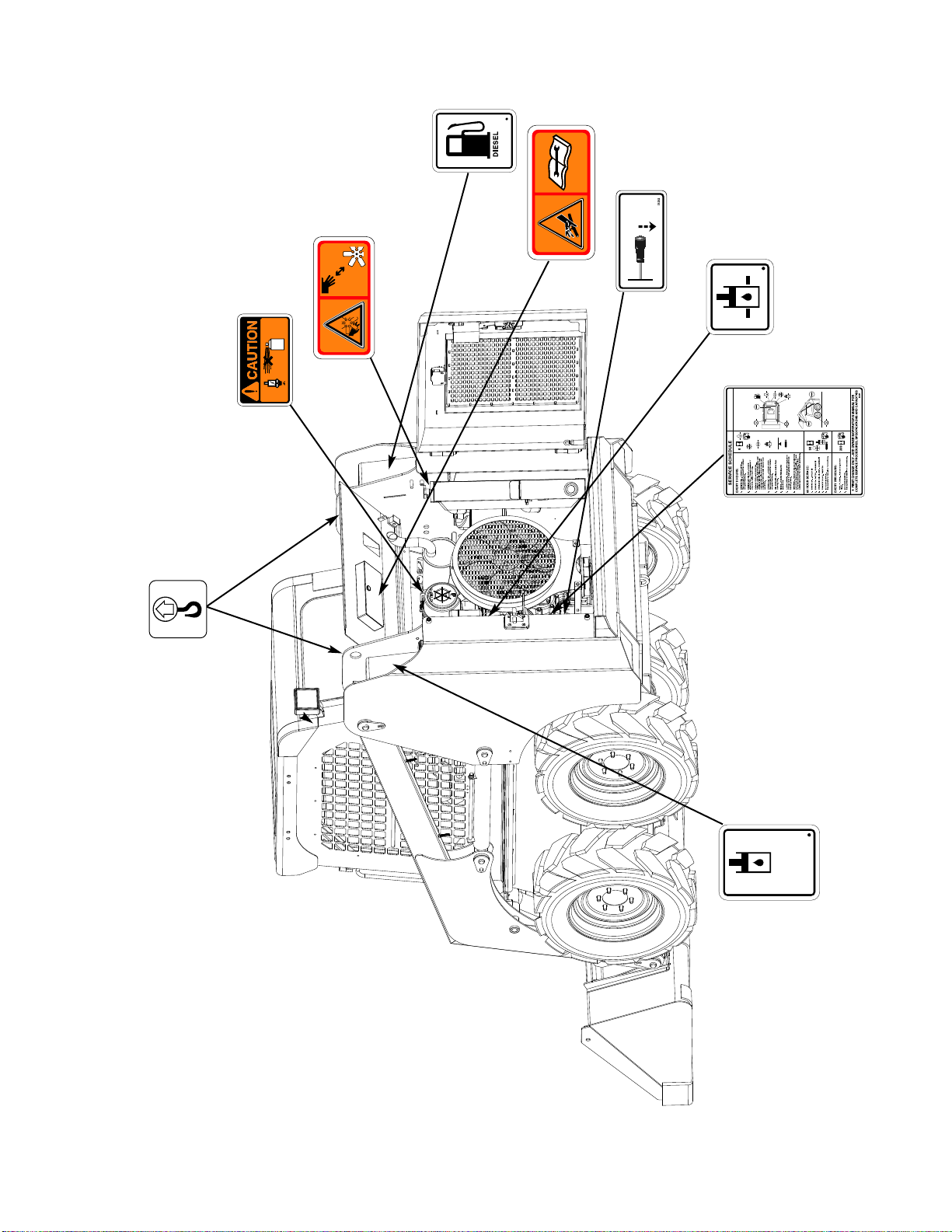
71
5.3 DECALS
#23310
23310
46301
#46301
PUSH
LIFTARM
DOWNVALVE
#31292
#39191
39191
#23312
23312
41064
#41064
23308
#23308
#23321
50
HYDRAULIC
HYRAULICO
HYDRAULISCH
HYDRAULIQUE
#23307
23307

72
5.3 DECALS
#47265
DL 165
#41065
41065
#25460
25460
DONOTMOVELIFTARMWITH
SUPPORTERENGAGED
#47264
DL 165
#44615
DL 165
72
DL 165

Notes:

74
6. ATTACHMENTS AND BUCKETS
6. 1 SUNBEAR Approved Buckets and Attachments
6. ATT ACHMENTS AND BUCKETS

75
Cat. # Description Approx. W eight
941 9" X 48" (228.6 mm x 1219 mm) Auger Bits 75 lbs ( 34 kg )
943 12" X 48" (304.8 mm x 1219 mm) Auger Bit w/Serrated Edges 100 lbs ( 45.4 kg )
14" X 52" (355.6 mm x 1320.8 mm)Auger Bit w/Serrated Edges 105 lbs ( 47.6 kg )
120 16" X 52" (406.4 mm x 1320.8 mm) Auger Bit w/Serrated Edges 118 lbs ( 53.5 kg )
Post Hole Auger Bits
6. 1 SUNBEAR APPROVED BUCKETS AND A TTACHMENTS
Cat. # Description SAE Heaped Cap. (cu. ft.) Approx. Weight
1955 66" (1676 mm) Snow and Light Material Bucket 23.7 468 lb. (212.3 kg)
2667 66" (1676 mm) Dirt Bucket 12.85 425 lb. (192.8 kg)
2002 68" (1727 mm) Fertilizer Bucket 20.6 396 lb. (179.6 kg)
2007 66"(1676mm)High Capacity Bucket 28.7 495lb.(224.6KG)
3763 66"(1676mm)Produce Bucket
Buckets
Cat. #
Description Approx. Weight
2032
70" (1778 mm) Dozer Blade, Hydraulic Swing (1) 710 lbs. (322 kg)
Dozer Blade
6. A TTACHMENTS AND BUCKETS
Cat. # Description Approx. Weight
1943
Hydraulic Salt/Sand Spreader (1) 394 lb. (178. 7 kg)
Hydraulic Spreader
Cat. # Description Approx. W eight
2569 Model PA40 Auger Drive (Requires Mount and Bit) (1) 160 lb. (72.6 kg)
1891 Auger Mount 126 lb. (57.2 kg)
Post Hole Auger
Bucket Options
(1) Require Quick Coupling Kit
(1) Require Quick Coupling Kit
(1) Require Quick Coupling Kit
Cat. #
Description
Approx. Weight
2670
T
oothbar Complete for 66" Dirt Bucket
95 lb. (43.1 kg)
2668 Kit, Bolt-On Edge for 66" Bucket 90 lb. (40.8 kg)
3494
66" Bucket WithWeld On Teeth
3495
68" Bucket,U-1890 With Weld On Teeth
3496
68"Hi-Visib. Bucket,U-3181 With weld on Teeth
Cat. # Description Approx. Weight
1930 60" (1524 mm) Grapple Bucket 875 lb. (369.9kg)
Grapple Bucket
Cat. # Description Approx. W eight
1694 HH 300/500 Side Plates 200 lb. (91 kg)
1891 HH 300/500 Breaker Mount 192 lb. (87.1 kg)
Breaker Side Plates
(1) Require Quick Coupling Kit
119

Cat. # Description Approx. Weight
3349 HH 300-300 lb. Class Hydraulic Breaker (1) (2) 300 lb. (136 kg)
Hydraulic Breaker (REQUIRES SIDE PLATES, MOUNT & TOOL)
Cat. # Description
Approx. W eight
2330 Pallet Fork Frame (Requires Tines) 226 lb. (102.5 kg)
99 30" Tines (Set of Two) 110 lb. (49.9 kg)
98 36" Tines (Set of Two) 138 lb. (62.6 kg)
437 42" Tines (Set of Two) 149 lb. (67.6 kg)
2564 Tines (Set of Two) 160 lb. (72.6 kg)
Pallet Fork
Cat. # Description Approx. W eight
2213 BH 108 Backhoe Base Unit (1) (2) 780 lb. (353.8 kg)
2211 External Controls (1) 470 lb. (213.2 kg)
2222 Internal Controls (1) 470 lb. (213.2 kg)
2234 Mounting Kit (1)
2235 English Manuals and Decals (1) 1 lb. (0.5 kg)
1483 12" Bucket w/Teeth (1) 120 lb. (54.4 kg)
1482 18" Bucket w/Teeth (1) 140 lb. (63.5 kg)
1481 22" Bucket w/Teeth (1) 160 lb. (72.6 kg)
BH 108 Backhoe
(1) Use Of ACab Door Recommended With This Attachment
(2) Prices Are FOB Glendale Hts., IL.
(1) Order one each base unit, controls, mount, manual & bucket.
(2) Includes flat face quick coupling kit.
6. A TTACHMENTS AND BUCKETS
6. 1 SUNBEAR APPROVED BUCKETS AND ATT ACHMENTS (Continued)
Cat. # Description Approx. Weight
1533 Moil Point - DB10 25 lb. (11.3 kg)
1534 Chisel Point - DB10 35 lbs. (16 kg)
1535 Blunt Point - DB10 35 lbs. (16 kg)
1570 Asphalt Cutter - DB10 41 lbs. (18.6 kg)
1571 T amping Pad, 12" x 12" 105 lbs. (47.6 kg)
1548 Gas Changer 2 lbs. (0.9 kg)
Breaker Tools
Cat. # Description Approx. W eight
2189 72" Brush (Requires quick coupler kit) 500 lbs. (226.8 kg)
2708 Pofit type quick coupler 5 lbs. (2.3 kg)
2873 Flat Face Type Quick Coupler
Bucket Brush
76

77
6. A TTACHMENTS AND BUCKETS
6. 1 SUNBEAR APPROVED BUCKETS AND A TTACHMENTS (Continued)
Cat. # Description Approx. Weight
2189 72" Angle Broom (Requires Quick Coupler Kit) 500 lb. (226.8 kg)
2708 Quick Coupler Kit, Poppet Style 5 lb. (2.3 kg)
2873 Quick Coupler Kit, Flat Face Style
Angle Broom
Cat. # Description Approx. Weight
1392 60" Bucket Sweeper Drive (Requires Quick Coupler, Plate, Bucket) 564 lb. (255.9 kg)
1428 72" Bucket Sweeper Drive (Req. CPLR, Plate, Bucket) (1) 660lb. (299 kg)
2708 Quick Coupler Kit. Poppet Style 5 lb. (2.3 kg)
2873 Quick Coupler Kit, Flat Face Style
1427 Backing Plate 5 lb. (2.3 kg)
1935 60" Flat Bottom Utility Bucket 386 lb. (175 kg)
1936 73" Utility Bucket 480 lb. (218 kg)
Bucket Sweeper
Cat. # Description Approx. Weight
1834 Gutter Brush (1) 80 lb. (36.3 kg)
1298 Water Sprinkler System (1) 50 lb. (22.7 kg)
Bucket Sweeper Options
(1) Dealer Assembly Required
(1) Dealer Assembly Required

78
INDEX
A
Accumulator 28
Air Cleaner 33,35,45
Attachments
Installing 16
Lists 74-75
Auxiliary Hydraulics
Connecting 14
Controls 14
Operation 24
Axle 38
B
Backfilling 23
Battery
Boost 47
Maintenance 37,47
Specification 66
Bearing,Axle 38
Boost Lug 47
Boosting Procedure 47
Brake
Override 41
Parking 12,36
C
Cab
Maintenance 37
Prop Rod 32
Tilting 32
Chain, Drive 36,38
Control Levers
Lever Function 13,15,36
Switch Function 9
Coolant 35,46
D
Decals 69,70,71
Digging 22
Dumping, Bucket 21,22
E
Electrical
Diagram 48-50
maintenance 37
Panel 17
Engine
Oil 30,42
Relay, Preheat 17
Shut-down 20
Specifications 42
Speed 35
Starting 19
V-Belt Tension 43
Exhaust 35
F
Fan 36
Filters, Replace
Air 45
Engine 42
Fuel 43
Hydraulic Oil 40
Final Drive 38
Foreword 4
Fuel Gauge 8
Fuel System 35,43
Bleeding 44
Fuse Panel 17
G
Greasing 34
H
Hoses And Pipes 36
Hour Meter 8
Hydraulic Function 36
Hydraulic/Hydrostastic 36
Circuits 58,59
Motor 36
Oil Filter 36

INDEX
I
Ignition Switch 8
Indexes, Sections
Section 1 3
Section 2, Controls 7
Section 3, Operation 18
Section 4, Maintenance 29
Section 5, Decals 64
Indicator Lights 8,9
Inspection, Pre-Start 19
Instrument Panel 8,9
L
Leveling 23
Liftarm
Control 15
Lowering 27
Support 13,32,36
Lifting 25
Lubrication 34,37
M
Maintenance
Schedule 30
Special Tools 60-62
O
Oil Cooler 35,36,41
Oil, Engine 30,34,35,36,42
Hydraulic 30,33,36,39,40
Transmission 30,36,38
Operational Procedures 20-24
P
Pump 36
Q
Quick-Tach 37
R
Radiator/Oil Cooler 35,41
S
Safety Precautions 5,6
Seal, Axle 36
Seat 10
Seat Bar 11,36
Seat Belt 36
Seat Switch 36
Service Access 32
Service
Daily 33-35
50 hr 35-37
200 hr 37
Service Schedule 30-31
Shields 37
Shut-off Procedure 20-26
Slopes
Travel on 20
Parkingon 6
Specifications, Loader 65,66,67,68
Sprocket 38
tarter 37
S
tarting Procedure 19
S
teering Control 13
T
Throttle 12,36
T
ilt Cab 32
T
ires
Maintenance 51
Pressure 37,51
Rotation 51
T
owing 25
T
ransporting 26
T
roubleshooting 52-57
T
urning 13-20
V
V
-Belt Tension 43
W
Warranty Statement 2
Water Separator 43
Wheel Nuts 34,37
79

 Loading...