

Page 1
Installation Instructions
Through-the-Wall Air Conditioners
PTT122006
Page 2

TABLE OF CONTENTS
HOW TO INSTALL 3
INSTALLATION KIT 5
PRE-INSTALLATION 5
WALL SLEEVE BRAND: EMERSON (15” DEEP) 6
WALL SLEEVE BRAND: WHIRLPOOL (17 1/8” DEEP) 6
WALL SLEEVE BRAND: FEDDERS (19 3/4” DEEP) 7
WALL SLEEVE BRAND: WHITE-WESTINGHOUSE, FRIGIDAIRE,
SUNBEAM, CARRIER 52F SERIES (22” DEEP) 7
WALL SLEEVE BRAND: GENERAL ELECTRIC, HOTPOINT
(16 7/8” DEEP) 8
WALL SLEEVE BRAND: SEARS, CARRIER 51S SERIES
(18 5/8” DEEP) 8
WALL SLEEVE BRAND: WHIRLPOOL (23” DEEP) 9
WALL SLEEVE BRAND: WHITE-WESTINGHOUSE, FRIGIDAIRE,
SUNBEAM (22” DEEP) 10
WALL SLEEVE BRAND: FEDDERS, FRIEDRICH (16 3/4” DEEP) 11
TRIM KIT ASSEMBLY 11
Page 3
HOW TO INSTALL
1. Identify the wall-sleeve brand you have from the chart below:
Brand Wall Sleeve Dimensions ( HxWxD)
White-Westinghouse 15 1/4” x 25 1/2” x 16, 17.5, or 22”
Frigidaire/Sunbeam 15 1/4” x 25 1/2” x 16, 17.5, or 22”
Carrier (52F series) 15 1/4” x 25 1/2” x 16, 17.5, or 22”
General Electric/Hotpoint 15 5/8” x 26” x 16 7/8”
Whirlpool 16 1/2” x 25 7/8” x 17 1/8 or 23”
Fedders/Emerson 16 3/4” x 27” x 16 3/4 or 19 3/4”
Sears/Kenmore 16 7/8” x 25 3/4 x 18 5/8”
Emerson/Fedders 15 3/4” x 26 3/4” x 15”
Carrier (51S series) 16 7/8” x 25 3/4” x 18 5/8”
Friedrich 16 3/4” x 27” x 16 3/4”
Notes:
All wall sleeves used to mount the new air conditioner must be in sound structural condition and
•
have a rear grille that securely attached to the sleeve or rear fl ange that serves as a stop for the air
conditioner.
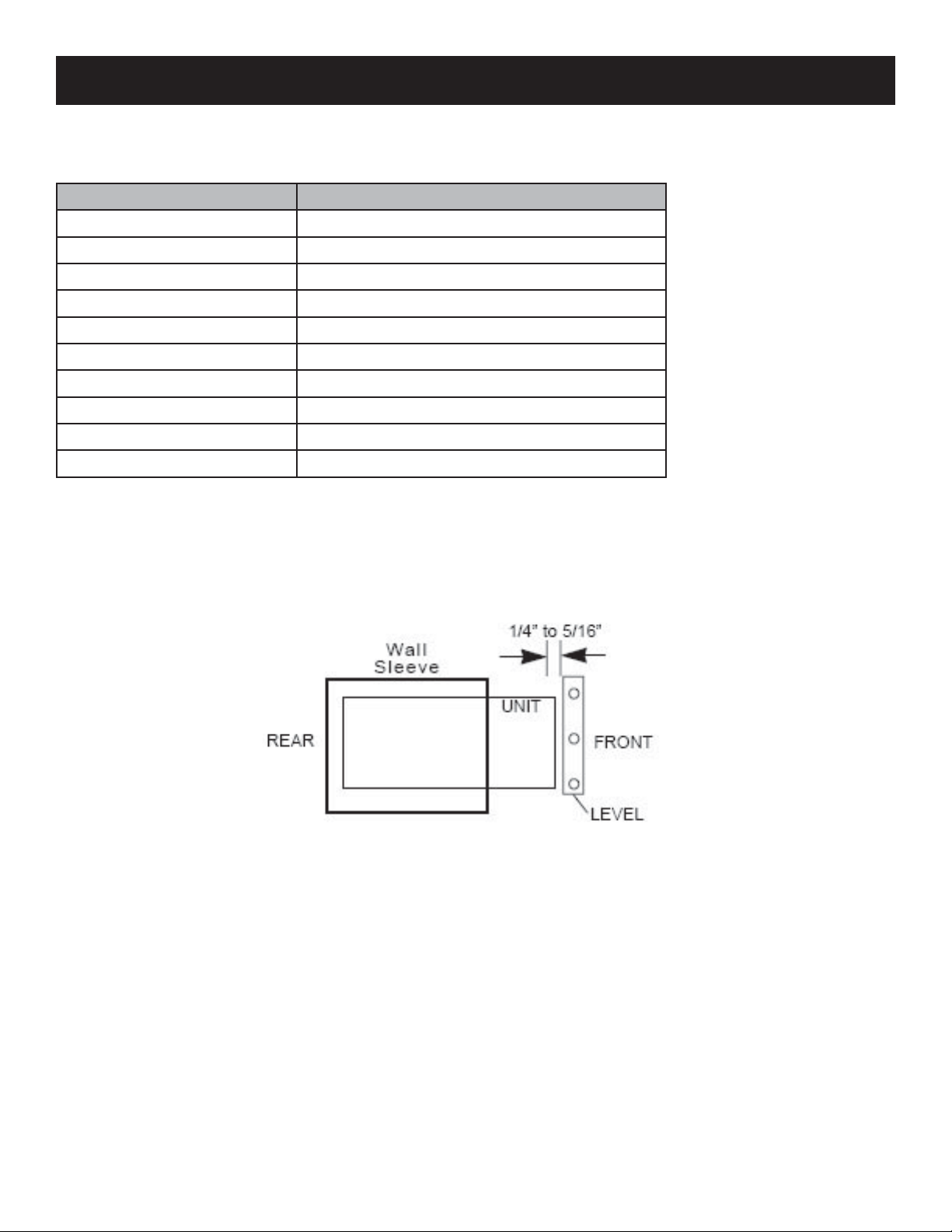
When the installation is complete, the replacement unit must have a rearward slope as shown.
•
2. Remove the old air conditioner from the wall sleeve and prepare wall sleeve as follows:
Clean interior
•
Wall sleeve must be securely fastened in the wall before installing your new air conditioner.
•
Drive more nails or screws through the sleeve and into the wall if necessary.
Repair paint if needed.
•
3
Page 4
HOW TO INSTALL (cont’d)
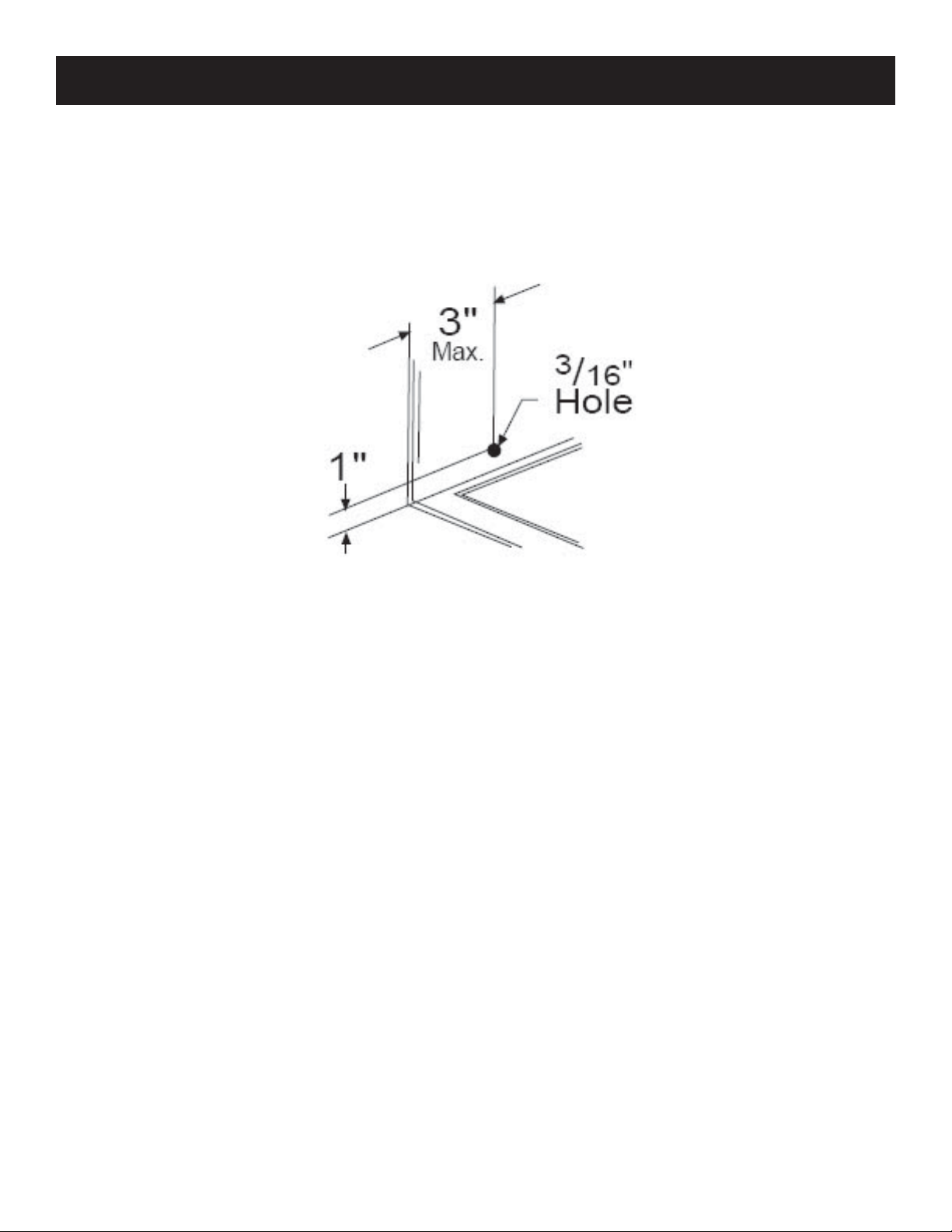
If the sleeve is not already in the wall, drill a 3/16” clearance hole for the grounding screw through
3.
the left side of the wall sleeve, in a clear area about 3” maximum back from the front edge of the
sleeve. Attach the ground wire inside the sleeve, using the grounding screw and a nut. Pull the loose
end of the grounding wire our from the front of the sleeve and temporarily bend it down and around
the lower edge of the sleeve.
Prepare the wall sleeve to install the new air conditioner. See the following pages of the manual for
4.
brand-specifi c installation instructions.
Install the new air conditioner into the wall sleeve.
5.
To attach the ground wire to the new air conditioner, remove the screw from the left front side.
6.
Assemble and install the Trim Frame (see Trim Frame Assembly section in manual).
7.
4
Page 5

INSTALLATION KIT
You may not need all parts in this kit. Discard any unused parts.
Part Specifi cations Quantity
Tapered Spacer Blocks 17” 2
Centering/Support Blocks 4.5” x 3.5” x 1.5” 2
Plastic Divider 1/8” x 4.5” x 14.5” 1
Stuffer Seal 1” x 1.5” x 84” 1
Seal 1.5” x 1.5” x 14” 2
Seal 1.5” x 1.5” x 26.5” 2
Seal 1.5” x 1.5” x 14” 2
Seal 1.5” x 3/8” x 26.5” 2
Seal 1.5” x 3/8” x 14” 1
Seal 1” x 3/4” x 14” 2
Trim Frame (side legs) 2
Trim Frame (top and bottom legs) 1
Ground Wire (green) 1
Nut for Grounding Screw 1
Grille (plastic) 1
Nuts (plastic) 4
Screw with Washer 4
PRE-INSTALLATION
If you are installing your air conditioner into an existing sleeve and there is an existing rear grille, the
louvers will have to be bent as per the instructions at the beginning of each section. If this does not
work,
Remove the existing grille.
1.
Place the included aluminum grille towards the rear of the unit.
2.
Mark through the hole positions.
3.
Drill through the sleeve fl anges with an 1/8” drill bit.
4.
Attach the new grille with the self-threading screws and washers (not included).
5.
It is very important that the partition be placed on the left side of the sleeve.
OR
Remove the existing grille.
1.
Use the included plastic grille and secure to sleeve fl anges using the existing screws and washers.
2.
5
Page 6

WALL SLEEVE BRAND: Emerson (15” deep)
Redirect the louvers at the back of the wall sleeve.
1.
Attach (1) 1 1/2” x 3/8” x 25” seal in the center at the top of
2.
the sleeve. Remove the backing paper and press into position.
Attach (2) 1 1/2” x 3/8” x 14” seals to the left and right sides
3.
of the sleeve.
Cut the 1 1/2” x 3/8” x 25” seal to 14” and attach to the
4.
vertical section of th rear grille.
Attach (2) 4 1/2” x 3 1/2” x 1 1/2” centering/support blocks,
5.
one on each side wall. Place in the center side wall with the
tapered end facing the opening.
Gently slide the air conditioner into the sleeve.
6.
Before sliding the unit all the way in, remove the second screw and washer from the front-left side of
7.
the unit.
Screw and attach the other end of the ground wire to the unit, making sure the toothed washer is
8.
against the cabinet.
Install the 1” x 1 1/2” x 84” stuffer seal between the wall sleeve and the air conditioner.
9.
Assemble and install the trim frame (see “Trim Frame Assembly” section of manual).
10.
WALL SLEEVE BRAND: Whirlpool (17 1/8” deep)
Redirect the louvers at the back of the wall sleeve.
1.
Attach (2) tapered spacer blocks to the inside wall of the sleeve
2.
with the tapered end 1/2” from the back of the sleeve.
Attach (1) 1 1/2” x 1 1/2” x 25” seal in the center at the top of
3.
the sleeve. Remove the backing paper and press into position.
Attach (2) 1 1/2” x 3/8” x 14” seals to the left and right sides
4.
of the sleeve.
Cut the 1 1/2” x 3/8” x 25” seal to 14” and attach it to the
5.
vertical section of the rear grille.
Gently slide the air conditioner into the sleeve.
6.
Before sliding the unit all the way in, remove the second screw and washer from the front-left side of
7.
the unit.
Screw and attach the other end of the ground wire to the unit, making sure the toothed washer is
8.
against the cabinet.
Install the 1” x 1 1/2” x 84” stuffer seal between the wall sleeve and the air conditioner.
9.
Assemble and install the trim frame (see “Trim Frame Assembly” section of manual).
10.
6
Page 7

WALL SLEEVE BRAND: Fedders (19 3/4” deep)
Redirect the louvers at the back of the wall sleeve.
1.
Attach the (2) 4 1/2” x 3 1/2” x 1 1/2” centering/support
2.
blocks, one on each side wall. Place in the center of the side
wall with the tapered end facing the sleeve opening.
Cut (2) 17” tapered spacer blocks into two pieces, 4” and 13”
3.
each.
Place the 4” section in front of the rib on the base, with the
4.
tapered end facing the back of the sleeve. The remaining
portion should be placed behind the rib again, sloping toward
the rear of the unit.
Attach (1) 1 1/2” x 3/8” x 25” seal in the center at the top of
5.
the sleeve. Remove the backing paper and press into position.
Attach (2) 1 1/2” x 3/8” x 25” seals to the left and right sides
6.
of the sleeve.
Cut the 1 1/2 x 3/8” x 25” seal to 14” and attach it to the
7.
vertical section of the rear grille.
Gently slide the air conditioner into the sleeve.
8.
Before sliding the unit all the way in, remove the second screw and washer from the front-left side of
9.
the unit.
Screw and attach the other end of the ground wire to the unit, making sure the toothed washer is
10.
against the cabinet.
Install the 1” x 1 1/2” x 84” stuffer seal between the wall sleeve and the air conditioner.
11.
Assemble and install the trim frame (see “Trim Frame Assembly” section of manual).
12.
WALL SLEEVE BRAND: White-Westinghouse, Frigidaire,
Sunbeam, Carrier 52F series (22” deep)
If the wall sleeve does not have a rear grille or louvered panel, install the plastic grille included in the
1.
kit. The plastic grille is mounted to the inside of the wall sleeve at the rear fl anges. There are (4)
plastic nuts in the fl anges of the wall sleeve. If your sleeve is missing these nuts or they are damaged,
use the supplied replacement nuts and grill in the kit. The nuts are installed from the inside of the
sleeve and are pressed into the square holes of the rear fl anges. Place the grille against the rear
fl anges and use the (4) washer screws to secure the grille to the sleeve.
Attach (1) 1 1/2” x 3/8” x 25” seal in the center at the top of the sleeve. Remove the backing paper
2.
and press into position.
Attach (2) 1 1/2” x 3/8” x 25” seals to the left and right sides of the sleeve.
3.
Attach (1) 1” x 3/4” x 14” seal vertically 7” from the left side of the sleeve.
4.
Gently slide the air conditioner into the sleeve.
5.
Before sliding the unit all the way in, remove the second screw and washer from the front-left side of
6.
the unit.
Screw and attach the other end of the ground wire to the unit, making sure the toothed washer is
7.
against the cabinet.
Install the 1” x 1 1/2” x 84” stuffer seal between the wall sleeve and the air conditioner.
8.
Assemble and install the trim frame (see “Trim Frame Assembly” section of manual).
9.
7
Page 8

WALL SLEEVE BRAND: General Electric, Hotpoint
(16 7/8” deep)
Redirect the louvers at the back of the wall sleeve.
1.
Cut (2) 17” tapered spacer blocks into two pieces, 4” and 13”
2.
each, and install with the tapered end 1/2” from the back of the
sleeve.
Attach (1) 1 1/2” x 3/8” x 25” seal in the center at the top of
3.
the sleeve. Remove the backing paper and press into position.
Attach (2) 1 1/2” x 3/8” x 14” seals to the left and right sides
4.
of the sleeve.
Cut the 1 1/2” x 3/8” x 25” seal to 14” and attach it to the
5.
vertical section of the rear grille.
Gently slide the air conditioner into the sleeve.
6.
Before sliding the unit all the way in, remove the second screw
7.
and washer from the front-left side of the unit.
Screw and attach the other end of the ground wire to the unit,
8.
making sure the toothed washer is against the cabinet.
Install the 1” x 1 1/2” x 84” stuffer seal between the wall sleeve
9.
and the air conditioner.
Assemble and install the trim frame (see “Trim Frame
10.
Assembly” section of manual).
WALL SLEEVE BRAND: Sears, Carrier 51S series
(18 5/8” deep)
Redirect the louvers at the back of the wall sleeve.
1.
Attach (2) tapered spacer blocks to the inside wall of the sleeve
2.
with the tapered end 1/2” from the back of the sleeve.
Attach (1) 1 1/2” x 1 1/2” x 25” seal in the center at the top of
3.
the sleeve. Remove the backing paper and press into position.
Attach (2) 1 1/2” x 3/8” x 14” seals to the left and right sides
4.
of the sleeve.
Cut the 1 1/2” x 3/8” x 25” seal to 14” and attach it to the
5.
vertical section of the rear grille.
Gently slide the air conditioner into the sleeve.
6.
Before sliding the unit all the way in, remove the second screw and washer from the front-left side of
7.
the unit.
Screw and attach the other end of the ground wire to the unit, making sure the toothed washer is
8.
against the cabinet.
Install the 1” x 1 1/2” x 84” stuffer seal between the wall sleeve and the air conditioner.
9.
Assemble and install the trim frame (see “Trim Frame Assembly” section of manual).
10.
8
Page 9

WALL SLEEVE BRAND: Whirlpool (23” deep)
Redirect the louvers at the back of the wall sleeve.
1.
Because of the increased unit depth, fi rst try fi tting the unit using the
following steps:
Place (2) 1 1/2” x 1 1/2” x 14” seals against each side.
2.
Gently slide the unit into the sleeve and check if the amount
3.
extending from the sleeve is suffi cient once the trim frame is
attached.
If the position is acceptable, remove the unit and continue
4.
following these steps. If not, skip to the steps below.
Attach (1) 1 1/2” x 1 1/2” x 25” seal in the center at the top of
5.
the sleeve. Remove the backing paper and press into position.
Attach (2) 1 1/2” x 1 1/2” x 14” seals to the left and right sides of the sleeve.
6.
Cut the 1 1/2” x 1 1/2” x 25” seal to 14” and attach it vertically to the rear grille, 7” from the left
7.
side.
Attach the tapered spacer blocks to the fl oor of the sleeve.
8.
Gently slide the air conditioner into the sleeve.
9.
Before sliding the unit all the way in, remove the second screw and washer from the front-left side of
10.
the unit.
Screw and attach the other end of the ground wire to the unit, making sure the toothed washer is
11.
against the cabinet.
Install the 1” x 1 1/2” x 84” stuffer seal between the wall sleeve and the air conditioner.
12.
Assemble and install the trim frame (see “Trim Frame Assembly” section of manual).
13.
If the unit requires extra extension into the room, follow these steps:
Attach 1” x 3/4” x 14” seal over the solid vertical portion of the rear grille.
2.
Attach (2) 4 1/2” x 3 1/2” x 1 1/2” foam blocks with the slot overlapping the seal above.
3.
Install the divider into the slots of the foam blocks. You may need to trim the length to size.
4.
Cut the 1 1/2” x 1 1/2” x 25” seal to fi t the top of the sleeve. The pieces must be fl ush to the edge
5.
of the divider.
Attach (2) 1 1/2” x 1 1/2” x 14” seals along the sides of the sleeve, again making sure all seals are
6.
fl ush.
Gently slide the air conditioner into the sleeve.
7.
Before sliding the unit all the way in, remove the second screw and washer from the front-left side of
8.
the unit.
Screw and attach the other end of the ground wire to the unit, making sure the toothed washer is
9.
against the cabinet.
Install the 1” x 1 1/2” x 84” stuffer seal between the wall sleeve and the air conditioner.
10.
Assemble and install the trim frame (see “Trim Frame Assembly” section of manual).
11.
9
Page 10

WALL SLEEVE BRAND: White-Westinghouse, Frigidiare,
Sunbeam (22” deep)
Redirect the louvers at the back of the wall sleeve.
1.
Because of the increased unit depth, fi rst try fi tting the unit using the following steps:
Place (2) 1 1/2” x 1 1/2” x 14” seals against each side.
2.
Gently slide the unit into the sleeve and check if the amount extending from the sleeve is suffi cient
3.
once the trim frame is attached.
If the position is acceptable, remove the unit and continue following these steps. If not, skip to the
4.
steps below.
Attach (1) 1 1/2” x 1 1/2” x 25” seal in the center at the top of the sleeve. Remove the backing
5.
paper and press into position.
Attach (2) 1 1/2” x 1 1/2” x 14” seals to the left and right sides of the sleeve.
6.
Cut the 1 1/2” x 1 1/2” x 25” seal to 14” and attach it vertically to the rear grille, 7” from the left
7.
side.
Attach the tapered spacer blocks to the fl oor of the sleeve.
8.
Gently slide the air conditioner into the sleeve.
9.
Before sliding the unit all the way in, remove the second screw and washer from the front-left side of
10.
the unit.
Screw and attach the other end of the ground wire to the unit, making sure the toothed washer is
11.
against the cabinet.
Install the 1” x 1 1/2” x 84” stuffer seal between the wall sleeve and the air conditioner.
12.
Assemble and install the trim frame (see “Trim Frame Assembly” section of manual).
13.
If the unit requires extra extension into the room, follow these steps:
Attach 1” x 3/4” x 14” seal over the solid vertical portion of the rear grille.
2.
Attach (2) 4 1/2” x 3 1/2” x 1 1/2” foam blocks with the slot overlapping the seal above.
3.
Install the divider into the slots of the foam blocks. You may need to trim the length to size.
4.
Cut the 1 1/2” x 1 1/2” x 25” seal to fi t the top of the sleeve. The pieces must be fl ush to the edge
5.
of the divider.
Attach (2) 1 1/2” x 1 1/2” x 14” seals along the sides of the sleeve, again making sure all seals are
6.
fl ush.
Gently slide the air conditioner into the sleeve.
7.
Before sliding the unit all the way in, remove the second screw and washer from the front-left side of
8.
the unit.
Screw and attach the other end of the ground wire to the unit, making sure the toothed washer is
9.
against the cabinet.
Install the 1” x 1 1/2” x 84” stuffer seal between the wall sleeve and the air conditioner.
10.
Assemble and install the trim frame (see “Trim Frame Assembly” section of manual).
11.
10
Page 11

WALL SLEEVE BRAND: Fedders, Friedrich
(16 3/4” deep)
Redirect the louvers at the back of the wall sleeve.
1.
Attach the (2) 4 1/2” x 3 1/2” x 1 1/2” centering/support
2.
blocks, one on each side wall. Place in the center of the side
wall with the tapered end facing the sleeve opening.
Cut (2) 17” tapered spacer blocks into two pieces, 2 1/2” and
3.
12 1/2” each.
Place the 2 1/2” section in front of the rib on the base, with
4.
the tapered end facing the back of the sleeve. The remaining
portion should be placed behind the rib again, sloping toward
the rear of the unit.
Attach (1) 1 1/2” x 3/8” x 25” seal in the center at the top of
5.
the sleeve. Remove the backing paper and press into position.
Attach (2) 1 1/2” x 3/8” x 25” seals to the left and right sides
6.
of the sleeve.
Cut the 1 1/2 x 3/8” x 25” seal to 14” and attach it to the
7.
vertical section of the rear grille.
Gently slide the air conditioner into the sleeve.
8.
Before sliding the unit all the way in, remove the second screw and washer from the front-left side of
9.
the unit.
Screw and attach the other end of the ground wire to the unit, making sure the toothed washer is
10.
against the cabinet.
Install the 1” x 1 1/2” x 84” stuffer seal between the wall sleeve and the air conditioner.
11.
Assemble and install the trim frame (see “Trim Frame Assembly” section of manual).
12.
TRIM FRAME ASSEMBLY
The purpose of the trim frame is to cover space between the wall sleeve and the replacement air
conditioner cabinet. Each frame is made of four parts.
To assemble the trim frame, insert the snaps of the side legs into the top and bottom legs.
1.
To install the trim frame to the sleeves, slide the frame over the cabinet until it is fl ush with the wall
2.
sleeve.
Note: Be sure to route the cord through the trim frame before placing the trim frame on the unit.
•
11
Page 12

© 2006 Sunbeam Products, Inc. doing business as Jarden Consumer Solutions. All rights reserved.
Sunbeam
®
is a registered trademark of Sunbeam Products, Inc. used under license.
Distributed by Petters Consumer Brands, LLC. 4400 Baker Road, Minnetonka, MN 55343.
For service, support and warranty information, visit www.sunbeammajorappliances.com or in the US call 1-866-866-6283.
 Loading...