

Page 1
PRODUCTS INC.
4101 Howard Bush Dr.
Neosho, Mo. 64850
INTERNET SITE:
www.bbqhq.com
1141-1986BX 99/10
ENGINEERING CODE
SD113232/SD113242
LOOK INSIDE FOR:
z
EASY ASSEMBLY
INSTRUCTIONS
z
IMPORTANT WARRANTY
INFORMATION
z
SAFETY AND
MAINTENANCE TIPS
z
FOR YOUR CONVENIENCE,
EXTRA HARDWARE MAY
BE INCLUDED.
Assembly
Instructions
TOOLS REQUIRED
#2 PHILLIPS SCREWDRIVER
PLIERS
HAMMER
BOX END WRENCH
Las Instrucciones de Ensamblaje en español en la pagina 15.
IMPORTANT! TO ENSURE PROPER
GAS FLOW, BURNER CONTROL
VALVES MUST
BE "OFF"
BEFORE
OPENING THE GAS CYLINDER
VALVE.
Page 2
(Pg. 2) 1141-1986
(2) Qty.
(2) Qty.
Hardware shown actual size
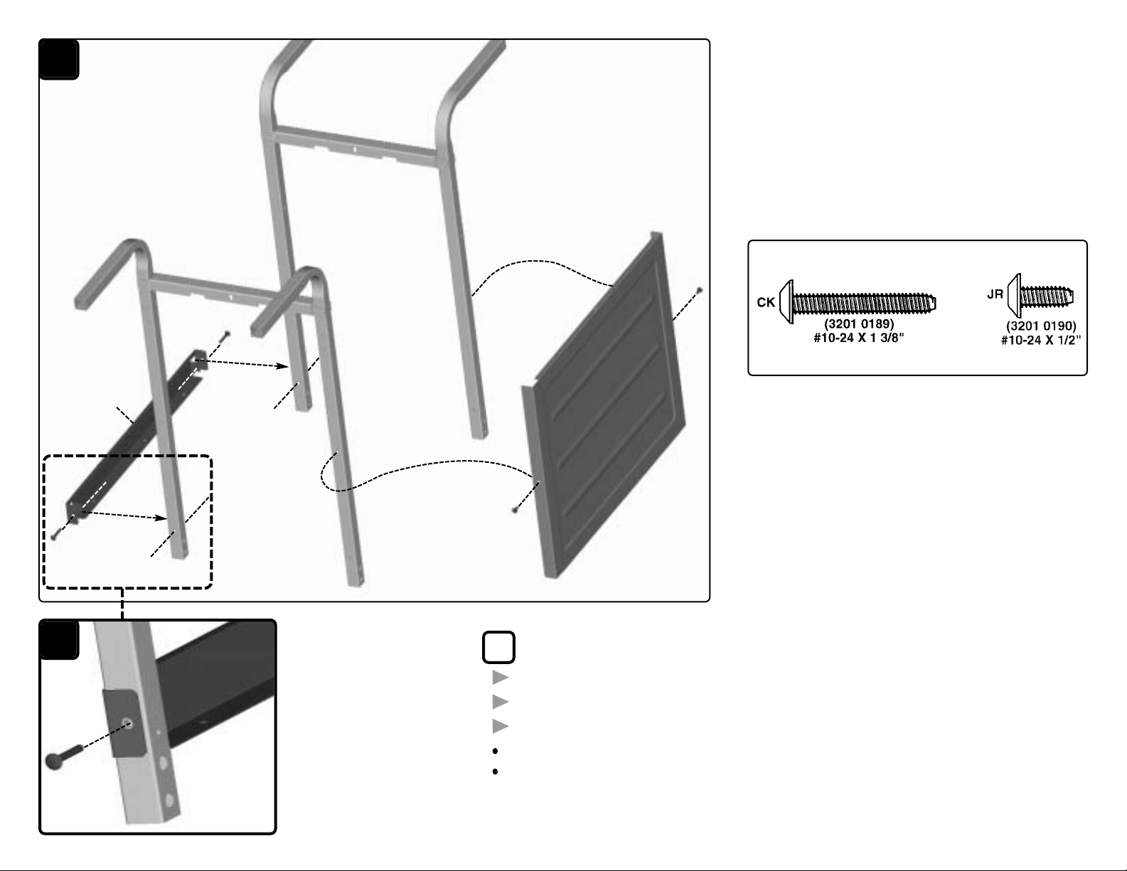
A Remove the following parts from the carton:
One STRAP . . . . . . . . . . . . . . . . . . . . . . . . . . . . . . . . . . . . . . . . . . . . . . . . . . . . . . . . . . . . . . . . . . .(1)
Two LEGS . . . . . . . . . . . . . . . . . . . . . . . . . . . . . . . . . . . . . . . . . . . . . . . . . . . . . . . . . . . . . . . . . . . . .(4)
One FRONT PANEL . . . . . . . . . . . . . . . . . . . . . . . . . . . . . . . . . . . . . . . . . . . . . . . . . . . . . . . . .(20)
Assemble the back STRAP (1) to LEGS (4) with two screws (CK). See detail A1.
Assemble the FRONT PANEL (20) to the front Legs with two screws (JR).
A
CK
CK
CK
JR
JR
4
4
20
1
1
Front
Right
Left
Back
label
A1
Page 3
(Pg. 3) 1141-1986
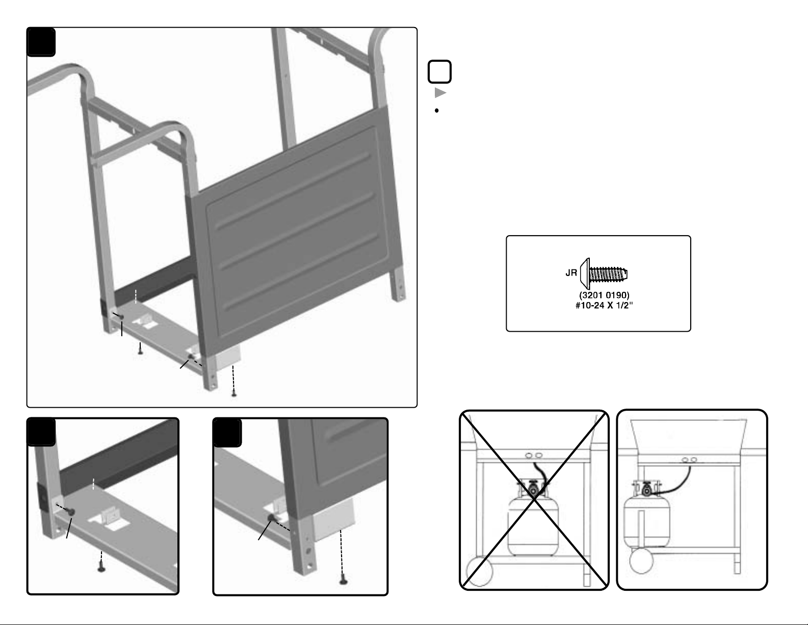
B Remove the following part from the carton:
One CYLINDER CADDY . . . . . . . . . . . . . . . . . . . . . . . . . . . . . . . . . . . . . . . . . . . . . . . . . . . .(2)
Attach the CYLINDER CADDY (2) onto the STRAP, LEGS and FRONT
PANEL with four screws (JR). Note: The Cylinder Caddy attaches to the
left end of the frame. See details B1 and B2.
(4) Qty.
Hardware shown actual size
B
B1
B2
JR
JR
JR
JR
2
JR
2
2
JR
Front
Right
Left
Back
JR
JR
INCORRECT CYLINDER CADDY
AND CYLINDER LOCATION
CORRECT CYLINDER CADDY
AND CYLINDER LOCATION
Page 4
(Pg. 4) 1141-1986
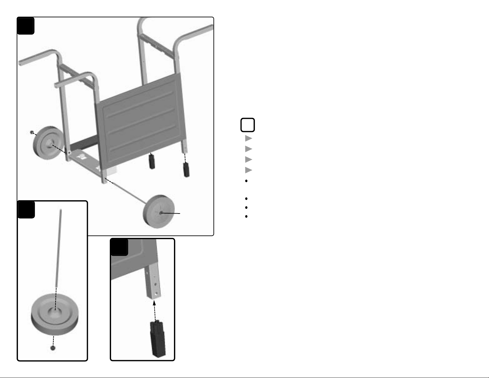
C Remove the following parts from the carton:
One AXLE . . . . . . . . . . . . . . . . . . . . . . . . . . . . . . . . . . . . . . . . . . . . . . . . . . . . . . . . . . . . . . . . . . . . .(3)
Two WHEELS . . . . . . . . . . . . . . . . . . . . . . . . . . . . . . . . . . . . . . . . . . . . . . . . . . . . . . . . . . . . . . . . .(16)
Two HUB CAPS . . . . . . . . . . . . . . . . . . . . . . . . . . . . . . . . . . . . . . . . . . . . . . . . . . . . . . . . . . . . . .(17)
Two LEG EXTENSIONS . . . . . . . . . . . . . . . . . . . . . . . . . . . . . . . . . . . . . . . . . . . . . . . . . . . . (18)
Tap one HUB CAP (17) onto AXLE (3). Slide a WHEEL (16) onto the Axle.
See detail C1.
Insert the Axle into the top axle holes on the left side of frame.
Slide other Wheel onto the axle and tap on remaining Hub Cap.
Tap two LEG EXTENSIONS (18) into the right legs. See detail C2.
C
C1
C2
16
16
16
17
17
17
3
3
18
18
18
Front
Right
Left
Back
Page 5
(Pg. 5) 1141-1986
E
49
49
E1
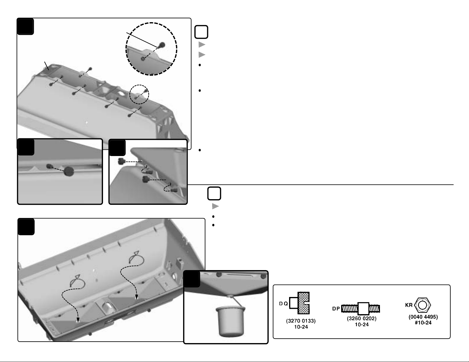
E Remove the following parts from the carton:
Two GREASE PAN WIRES . . . . . . . . . . . . . . . . . . . . . . . . . . . . . . . . . . . . . . . . . . . . . . . . .(49)
Thread the GREASE PAN WIRES (49) into the Grease drip pans.
Note: Soup can not included. See detail E1.
D Remove the following parts from the carton:
One BOTTOM CASTING . . . . . . . . . . . . . . . . . . . . . . . . . . . . . . . . . . . . . . . . . . . . . . . . . . . (42)
Two GREASE DRIP PANS . . . . . . . . . . . . . . . . . . . . . . . . . . . . . . . . . . . . . . . . . . . . . . . . .(48)
Set the BOTTOM CASTING (42) upside down. Install the long ends of six spacers (DP)
into the six tabs on the Bottom Casting secure inside with six hex nuts (KR). Note: The
Bottom casting front has only two tabs, the back has four tabs.
Remove the six knurl nuts (DQ) from the six spacers (DP). Do not loosen the spacers from
the hex nuts (KR) inside the bottom casting. Align the front hole in one of the GREASE
DRIP PANS (48) with spacer on the front of the bottom casting and insert the spacer into
the Grease pan. (Note: The front hole on the Grease pan is larger so it can slide over the
spacer.) See detail D1. Gently rotate pan and align the rear holes in the drip pan with the
spacers in the bottom casting. Then insert spacers into the pan and secure with three Knurl
nuts (DQ). See detail D2.
Repeat assembly for the other Grease Drip Pan.
Hardware shown actual size
(6) Qty.
(6) Qty
(6) Qty.
D
D1
D2
DQ
48
Back
Back
Front
DQ
DP
DP
42
KR
KR
KR
KR
KR
DP
DP
KR
DP
DP
DP
DQ
48
Long End
Soup can
not
included
Page 6
(Pg. 6) 1141-1986
Hardware shown actual size
(2) Qty.
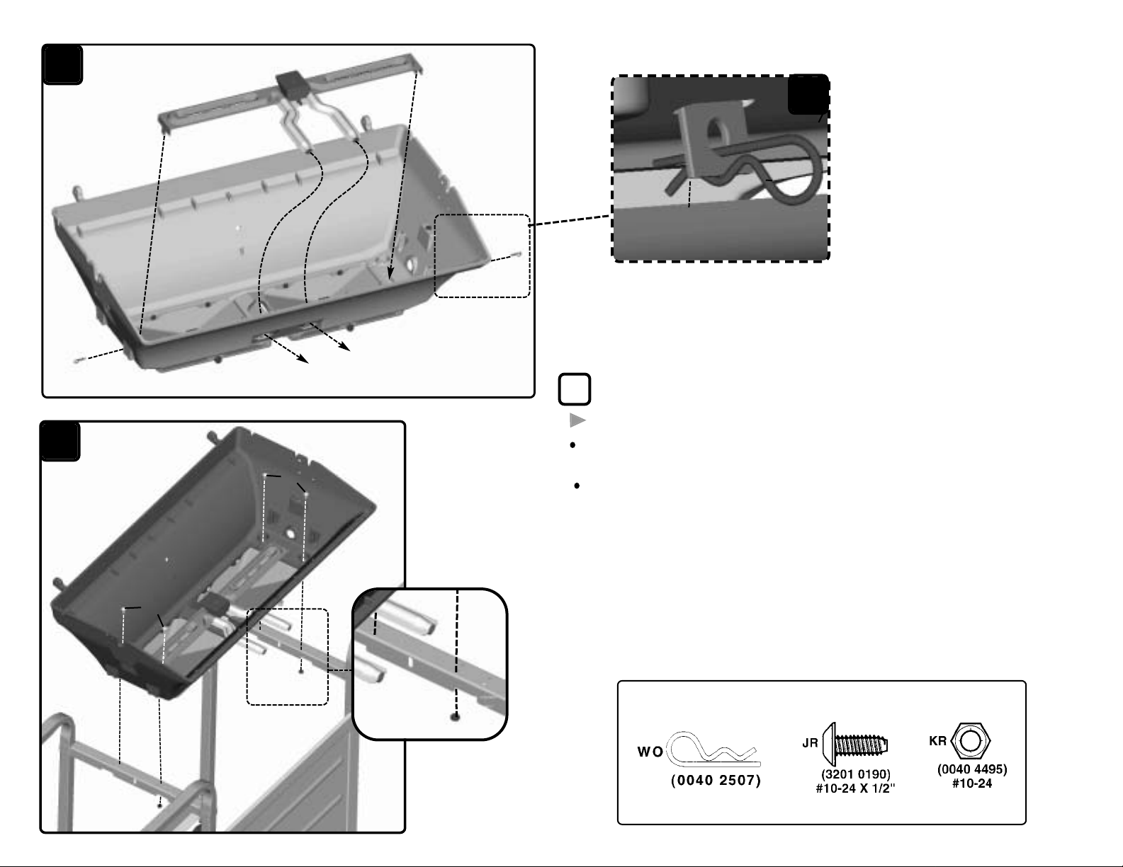
F Remove the following part from the carton:
One BURNER . . . . . . . . . . . . . . . . . . . . . . . . . . . . . . . . . . . . . . . . . . . . . . . . . . . . . . . . . . . . . . . . . (43)
Insert the BURNER (43) into the Bottom Casting slots and secure with two
hair pins (WO). See detail F1.
Attach the Bottom casting onto the Frame with four screws (JR) and two hex
nuts (KR). Attach two hex nuts (KR) on the front screws only. See detail F2.
WO
Burner
Tab
43
WO
WO
(2) Qty.
(4) Qty.
F
JR
JR
KR
KR
Front
Right
Left
Back
F2
F1
KR
Page 7
JR
44
G
JR
25
27
33
33
HA
HA
(Pg. 7) 1141-1986
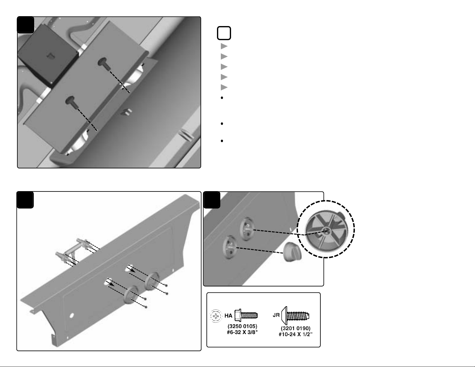
G Remove the following parts from the carton:
One CONTROL PANEL . . . . . . . . . . . . . . . . . . . . . . . . . . . . . . . . . . . . . . . . . . . . . . . . . . . . . (25)
One VALVE ASSEMBLY . . . . . . . . . . . . . . . . . . . . . . . . . . . . . . . . . . . . . . . . . . . . . . . . . . .(27)
Two CONTROL KNOBS . . . . . . . . . . . . . . . . . . . . . . . . . . . . . . . . . . . . . . . . . . . . . . . . . . . .(32)
Two BEZELS . . . . . . . . . . . . . . . . . . . . . . . . . . . . . . . . . . . . . . . . . . . . . . . . . . . . . . . . . . . . . . . . . . (33)
One VENTURI GUARD . . . . . . . . . . . . . . . . . . . . . . . . . . . . . . . . . . . . . . . . . . . . . . . . . . . . . .(44)
Attach the VENTURI GUARD (44) to the inside front of the Bottom casting with two
screws (JR). (DO NOT use a cordless or power screw drive, it can strip out the
screws.)
Attach the VALVE ASSEMBLY (27) and BEZELS (33) to the CONTROL PANEL
(25) with four screws (HA). See detail G1.
Push the CONTROL KNOBS (32) onto the Valve stems. See detail G2.
Hardware shown actual size
(4) Qty
(2) Qty.
G1
G2
32
Venturi Guard
32
Page 8
(Pg. 8) 1141-1986BX
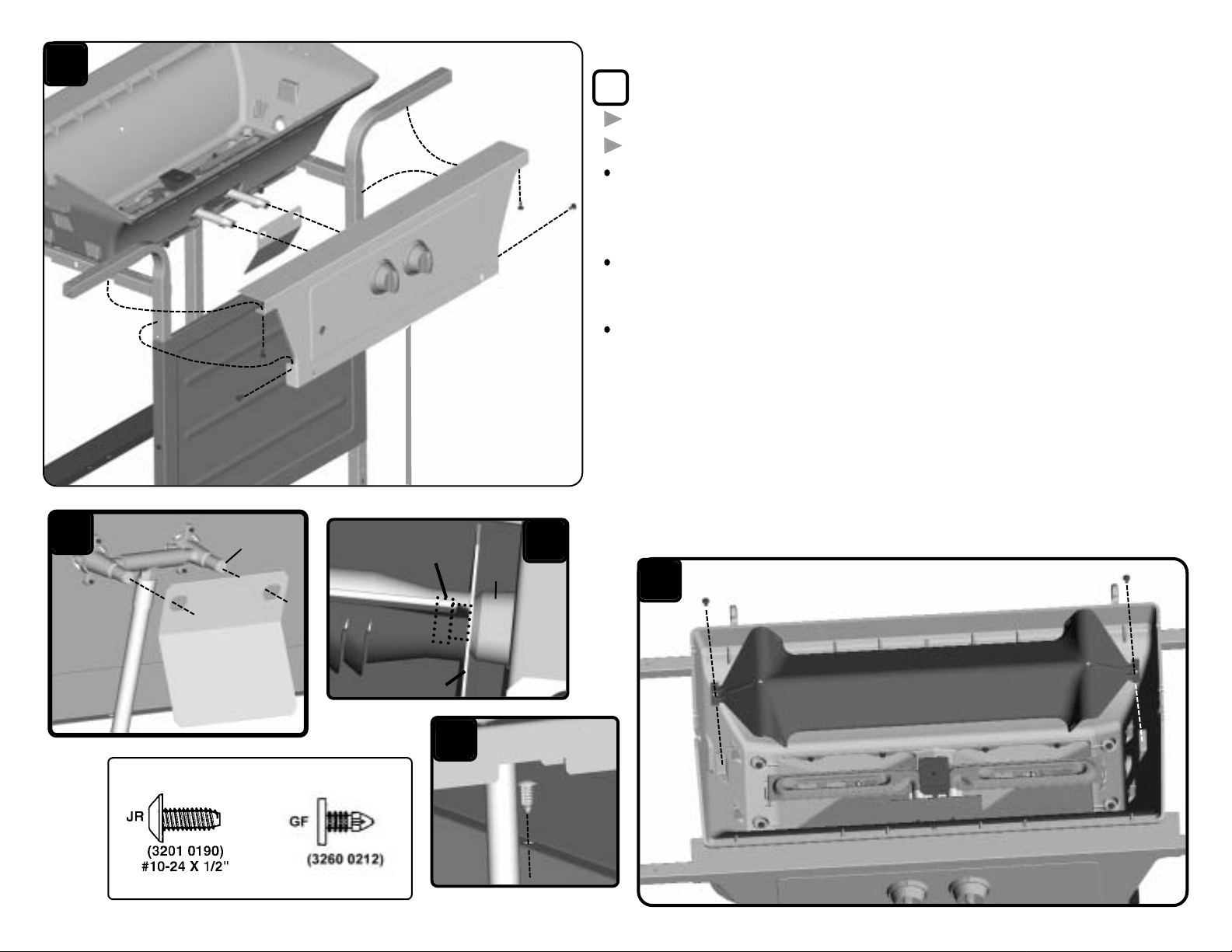
H Remove the following parts from the carton:
One HEAT SHIELD . . . . . . . . . . . . . . . . . . . . . . . . . . . . . . . . . . . . . . . . . . . . . . . . . . . . . . . . . .(47a)
One “I” TENT . . . . . . . . . . . . . . . . . . . . . . . . . . . . . . . . . . . . . . . . . . . . . . . . . . . . . . . . . . . . . . . . .(61)
Slide the HEAT SHIELD (47a) over the the Valve. See detail H1. Place the
Control Panel on the frame (place the HVR hose inside the front panel) insert
the orifices on the valve inside of the Burners’ venturi tubes. IMPORTANT: The
orifices must be inside the venturi tube. See detail H2.
Secure the Control Panel to the legs with four screws (JR). From inside frame
secure the bottom flange of the Control Panel and the Front panel top flange
together with one push in fastener (GF). See detail H3.
Place the “I” TENT (61) in the Bottom Casting over the Burner and secure with
two screws (JR). See detail H4.
Hardware shown actual size
(6) Qty.
(1) Qty.
GF
H1
47a
Inside
61
H4
JR
JR
H2
H3
Orifices inside of
venturi tubes
Valve
Orifice
heat shield
JR
JR
JR
JR
47a
H
Page 9
(Pg. 9) 1141-1986
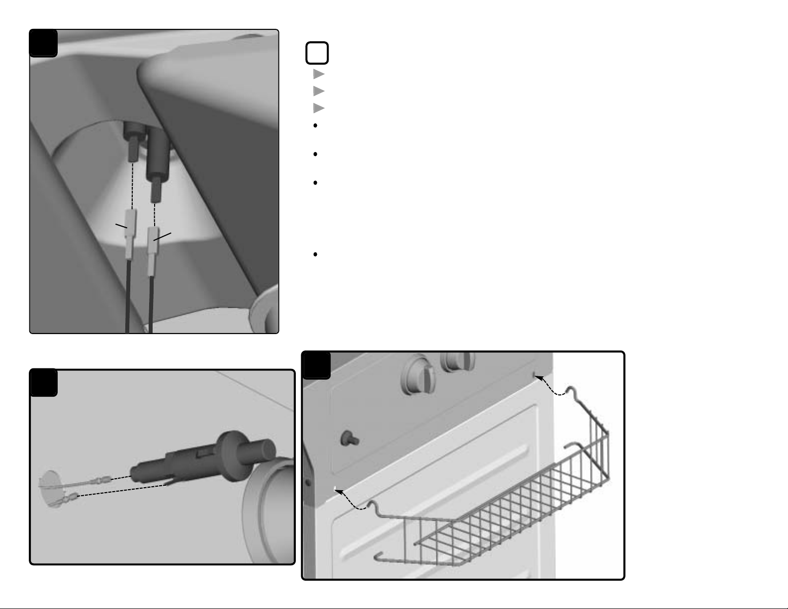
J Remove the following parts from the carton:
One FRONT BASKET . . . . . . . . . . . . . . . . . . . . . . . . . . . . . . . . . . . . . . . . . . . . . . . . . . . . . . . (22)
One PUSH BUTTON IGNITER . . . . . . . . . . . . . . . . . . . . . . . . . . . . . . . . . . . . . . . . . . . . . (26)
Two MAIN ELECTRODE WIRES . . . . . . . . . . . . . . . . . . . . . . . . . . . . . . . . . . . . . . . . . .(26b)
Push the MAIN ELECTRODE WIRES (26b) onto the main burner electrodes, located under the
bottom casting.
Thread the Main Electrode Wires through the igniter hole in the Control Panel. Push the round
connecters onto the round and flat pins on the PUSH BUTTON IGNITER (26). See detail J1.
Snap the Push Button Igniter into the Control Panel. Test: A spark should appear at electrode
tip.
If the spark does not appear.
- Check the wire connections to the Igniter.
- Check the wire connections to the main burner electrodes.
Hook the FRONT BASKET (22) Into the front panel. See detail J2.
J
J1
J2
26b
26b
22
26
Page 10
(Pg. 10) 1141-1986
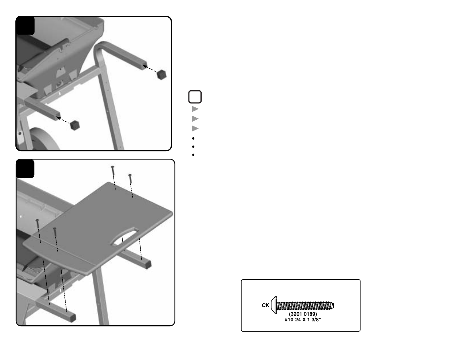
K Remove the following parts from the carton:
One right SIDE TABLE . . . . . . . . . . . . . . . . . . . . . . . . . . . . . (9R)
One left SIDE TABLE . . . . . . . . . . . . . . . . . . . . . . . . . . . . . . . (9L)
Four TUBE PLUGS . . . . . . . . . . . . . . . . . . . . . . . . . . . . . . . . .(15)
Insert two TUBE PLUGS (15) into the leg ends on the right side.
Attach one right SIDE TABLE (9R) to the right side with four screws (CK). See detail K1.
Repeat above assemblies for the Left SIDE TABLE (9L).
Hardware shown actual size
(8) Qty.
CK
CK
CK
9R
15
15
CK
K
K1
Right
Right
Page 11
(Pg. 11) 1141-1986
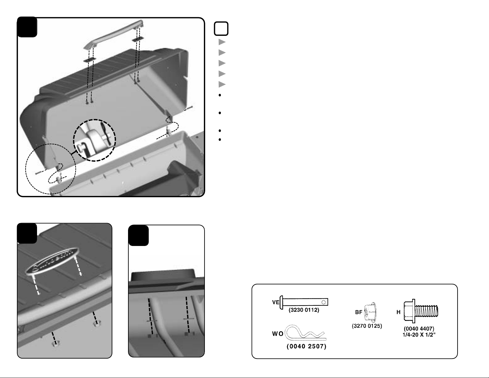
L Remove the following parts from the carton:
One HEAT INDICATOR . . . . . . . . . . . . . . . . . . . . . . . . . . . . . . . . . . . . . . . . . . . . . . . . . . . . .(54)
One GRILL LID . . . . . . . . . . . . . . . . . . . . . . . . . . . . . . . . . . . . . . . . . . . . . . . . . . . . . . . . . . . . . . . (55)
One NAMEPLATE . . . . . . . . . . . . . . . . . . . . . . . . . . . . . . . . . . . . . . . . . . . . . . . . . . . . . . . . . . .(56)
One FRONT HANDLE . . . . . . . . . . . . . . . . . . . . . . . . . . . . . . . . . . . . . . . . . . . . . . . . . . . . . . .(58)
Two FRONT HANDLE INSULATORS . . . . . . . . . . . . . . . . . . . . . . . . . . . . . . . . . . . . (59)
Set the GRILL LID (55) onto the grill bottom and secure with two clevis pins (VE) and
two hair pins (WO).
Assemble the FRONT HANDLE (58) to the GRILL LID with two FRONT HANDLE
INSULATORS (59) and four screws (H).
Attach the NAMEPLATE (56) to the Grill Lid with two nuts (BF). See detail L1.
Attach the HEAT INDICATOR (54) with two nuts. See detail L2.
L
L1
L2
WO
VE
WO
VE
55
58
56
H
H
BF
54
BF
59
59
(4) Qty
(2) Qty
(2) Qty
Hardware shown actual size
(2) Qty
Page 12
M
N
63
63
66
pivot wire
66
65
65
N1
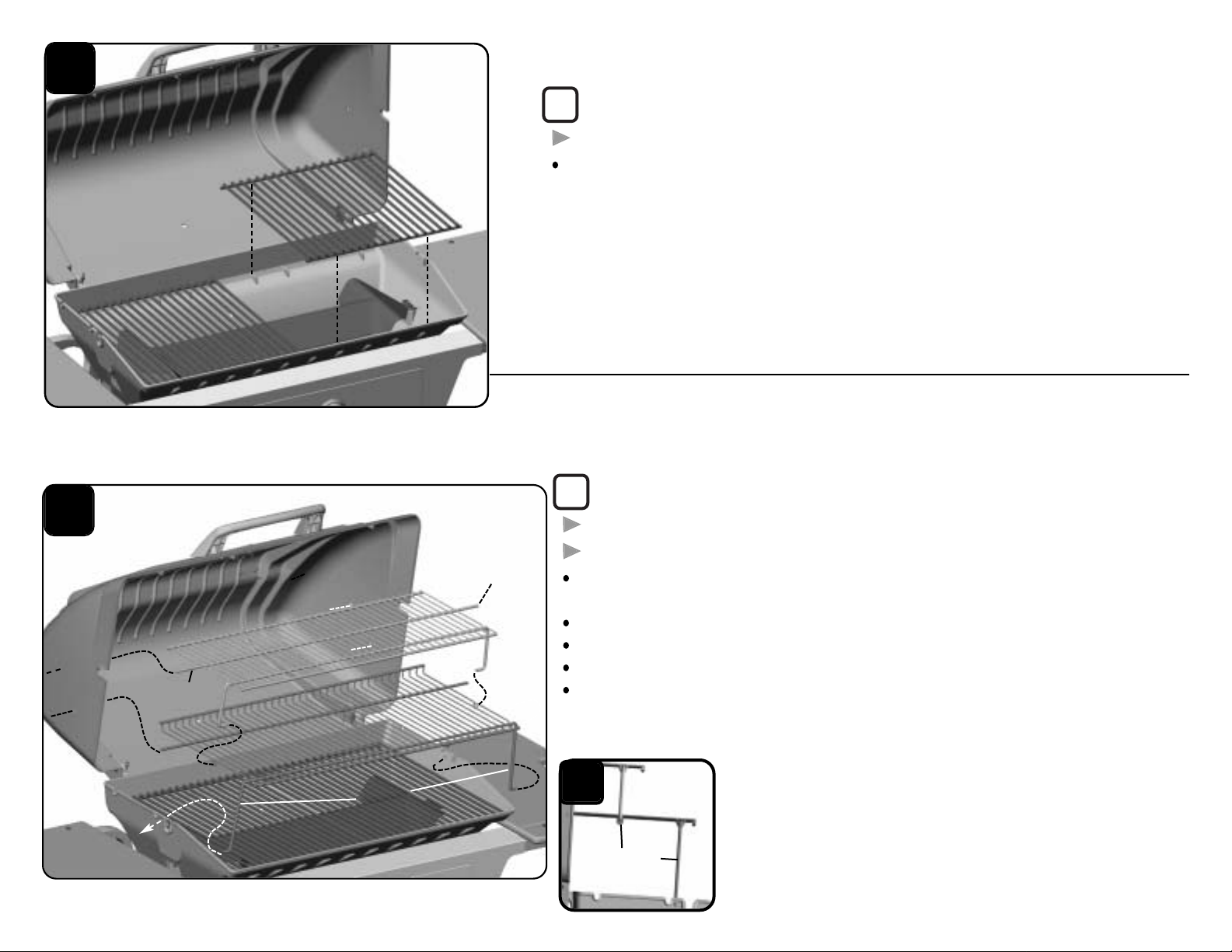
N Remove the following parts from the carton:
One WARMING RACK . . . . . . . . . . . . . . . . . . . . . . . . . . . . . . . . . . . . . . . . . . . . . . . . . . . . . .(65)
One TOP WARMING RACK . . . . . . . . . . . . . . . . . . . . . . . . . . . . . . . . . . . . . . . . . . . . . . . .(66)
Insert the long wire on the WARMING RACK (65) into the left side of the lid. Hold the
rack in a vertical position and insert right side into the lid.
To center the rack, slightly bend the pivot wires to adjust for a tight fit.
Lower rack and press the pivot wires into side holes. See detail N1.
Insert the long wire on the TOP WARMING RACK (66) into the upper holes in lid.
Hook the top pivot wire into bottom rack and to center, slightly bend wire for tight fit.
See detail N1.
(Pg. 12) 1141-1986
M Remove the following parts from the carton:
Two COOKING GRIDS . . . . . . . . . . . . . . . . . . . . . . . . . . . . . . . . . . . . . . . . . . . . . . . . . . . . . .(63)
Set the COOKING GRIDS (63) into the bottom casting.
long
wire
long
wire
pivot wire
pivot wire
Page 13
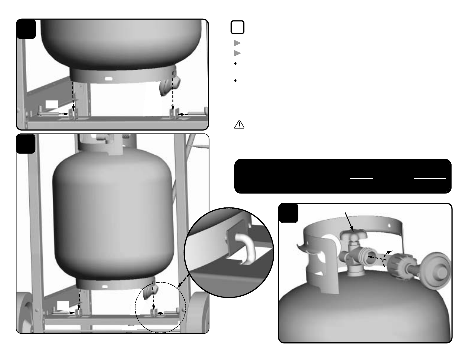
Remove the following parts from the carton:
Two CYLINDER PINS . . . . . . . . . . . . . . . . . . . . . . . . . . . . . . . . . . . . . . . . . . . . . .(78)
One CYLINDER . . . . . . . . . . . . . . . . . . . . . . . . . . . . . . . . . . . . . . . . . . . . . . . . . . . . . (79)
Set CYLINDER (79) on the Grill Frame and secure with the CYLINDER PINS
(78). See detail P1.
Remove plastic protective cap from TYPE 1 nipple! Insert the nipple of the
regulator (27) into the cylinder’s fuel valve inlet. See detail P2. Turn the
regulator hand wheel clockwise to tighten. No tools are needed. The Hand
Wheel will come to a complete stop when the connection is secure and gas
will not flow until a positive seal is achieved.
WARNING: During assembly of grill and when attaching or
replacing the L.P. gas cylinder, insure that the gas supply hose is free
of kinks and/or damage and is at least 3” away from hot surfaces such
as the grill casting.
P
79
78
78
78
78
79
BACK
79
27
78
R2
P1
P
(Pg. 13) 1141-1986A
*Cylinder Not Included
On
ENGINEERING CODE
SD113242
Gas Cylinder Valve
IMPORTANT! TO ENSURE PROPER GAS FLOW,
BURNER CONTROL VALVES MUST
BE "OFF"
BEFORE
OPENING THE GAS CYLINDER VALVE.
Page 14
(Pg. 14) 1141-1986BX
LIMITED WARRANTY
READ OWNER’S USE AND CARE MANUAL:
For proper filling and purging of the cylinder
For leak testing all gas supply connections
For correct grill lighting instructions
For use and storage of the grill and cylinder
WARNING! WHEN LEAK TESTING:
DO NOT smoke.
DO NOT use fire to test for leaks.
DANGER:
NEVER store a spare LP gas supply cylinder
under the grill body nor inside grill enclosure to
avoid the possibility of an explosion. Refer to the
Use and Care manual.
IMPORTANT:
Be sure to tighten up all hardware (screws, nuts,
bolts, etc.) at least once a year or each grilling
season.
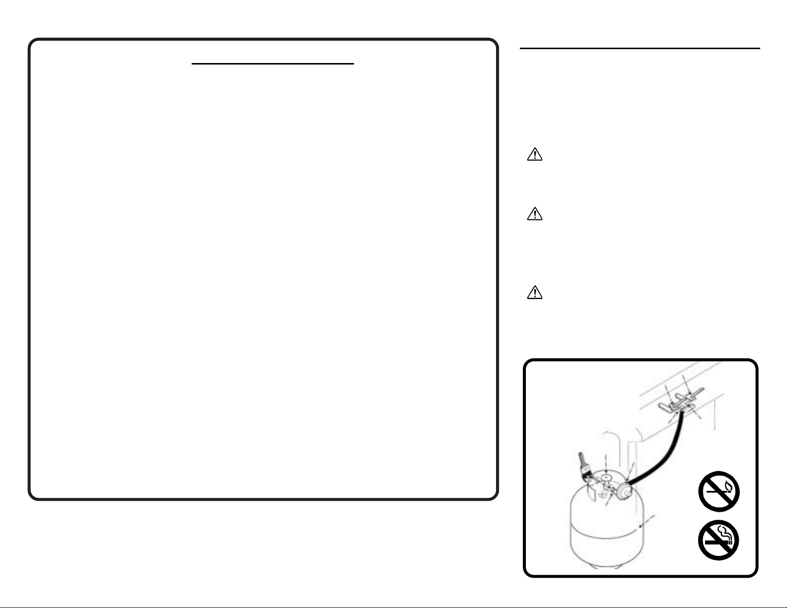
B
EFORE USING YOUR GRILL
LEAK TEST AREAS
(indicated by arrows)
SEE OWNER’S USE
AND
CARE MANUAL
Sunbeam Products, Inc. (“Sunbeam”) warrants that this product will be free from defects in material and
workmanship. This warranty applies to the following parts for the following time periods: the aluminum
castings are warranted for ten (10) years against burn through; the burner is warranted for five (5) years;
and all other parts are warranted for one (1) year, except the propane cylinder and paint finish. W e DO
NOT WARRANT in any way the propane cylinder (see label on cylinder for cylinder manufacturer’s
warranty) or the paint finish of the product. Sunbeam at its option, will repair or replace this product or
any component of the product found to be defective during the warranty period. Replacement will be
made with a new or remanufactured product or component. If the product is no longer available,
replacement may be made with a similar product of equal or greater value. This is your exclusive
warranty .
This warranty is valid for the original retail purchaser from the date of initial retail purchase and is not
transferable. Keep the original sales receipt. Proof of purchase is required to obtain warranty
performance. Sunbeam dealers, service centers, or retail stores selling Sunbeam products do not have
the right to alter, modify or any way change the terms and conditions of this warranty.
This warranty does not cover normal wear of parts or damage resulting from any of the following:
negligent use or misuse of the product, use on improper voltage or current, use contrary to the operating
instructions, disassembly, repair or alteration by anyone other than Sunbeam or an authorized service
center. Further, the warranty does not cover Acts of God, such as fire, flood, hurricanes and tornadoes.
Sunbeam shall not be liable for any incidental or consequential damages caused by the breach of any
express or implied warranty. Except to the extent prohibited by applicable law, any implied warranty of
merchantability or fitness for a particular purpose is limited in duration to the duration of the above
warranty. Some states, provinces or jurisdictions do not allow the exclusion or limitation of incidental
or consequential damages or limitations on how long an implied warranty lasts, so the above limitations
or exclusion may not apply to you. This warranty gives you specific legal rights, and you may also have
other rights that vary from state to state or province to province.
DO NOT RETURN THIS PRODUCT TO THE PLACE OF PURCHASE.
Take the product to an authorized Sunbeam service center. You can find the nearest authorized
Sunbeam service center by calling 1-800-641-2100.
NOT VALID IN MEXICO.
For WARRANTY, SERVICE and PARTS
Locate your model number and serial number on the label found on the back of your grill base.
Page 15

(Pg. 15) 1141-1986BX
PRODUCTS INC.
4101 Howard Bush Dr.
Neosho, Mo. 64850
PAGINA EN INTERNET:
www.bbqhq.com
BUSQUE LO SIGUIENTE
EN EL INTERIOR:
z
FACILES INSTRUCCIONES DE
ENSAMBLAJE
z
INFORMACION IMPORTANTE SOBRE
LA GARANTIA
z
CONSEJOS SOBRE SEGURIDAD Y
MANTENIMIENTO
z
PUEDE QUE SE INCLUYAN
HERRAJES ADICIONALES PARA SU
MAYOR COMODIDAD.
INSTRUCCIONES
DE ENSAMBLAJE
CODIGO DE INGENIERIA
SD113232/SD113242
HERRAMIENTAS
REQUERIDAS
· DESTORNILLADOR PHILLIPS NO.2
· ALICATES
· MARTILLO
· LLAVE DE TUBO
¡IMPORTANTE! PARA ASEGURAR UN
CORRECTO FLUIDO DE GAS, LAS
VALVULAS DE
CONTROL DE LOS QUEMADORES
DEBERAN ESTAR EN LA POSICION
"OFF"(APAGADO)
ANTES DE ABRIR LA VALVULA DE GAS
DEL TANQUE.
Page 16

(Pg. 16) 1141-1986
(2) Cdad.
(2) Cdad.
Los herrajes se muestran
en su tamaño real
A Extraer las siguientes piezas de la caja de cartón:
Una TIRA.............................................................................(1)
Dos PATAS..........................................................................(4)
Un PANEL FRONTAL .......................................................(20)
Ensamblar la TIRA POSTERIOR (1) en las PATAS (4) con dos tornillos (CK).
Ver la ilustración A1.
Ensamblar el PANEL FRONTAL (20) en las patas frontales utilizando dos tornillos
(JR).
A
CK
CK
CK
JR
JR
4
4
20
1
1
Parte frontal
Derecha
Izquierda
Parte posterior
Etiqueta
A1
Page 17

(Pg. 17) 1141-1986
B Extraer la siguiente pieza de la caja de cartón:
Un SOPORTE DE APOYO DEL TANQUE........................................(2)
Fijar el SOPORTE DE APOYO DEL TANQUE (2) sobre la TIRA,
PATAS y PANEL FRONTAL con cuatro tornillos (JR). Nota: El Soporte
de Apoyo del tanque se fija en el extremo izquierdo de la estructura.
Ver las ilustraciones B1 y B2.
(4) Cdad.
Los herrajes se muestran
en su tamaño real
B
B1
B2
JR
JR
JR
JR
2
JR
2
2
JR
Parte frontal
Derecha
Izquierda
Parte posterior
JR
JR
COLOCACION INCORRECTA DEL
TANQUE Y DEL CARRITO
COLOCACION CORRECTA DEL
TANQUE Y DEL CARRITO
Page 18

(Pg. 18) 1141-1986
C Extraer las siguientes piezas de la caja de cartón:
Un EJE ..........................................................................................(3)
Dos RUEDAS..............................................................................(16)
Dos TAPA CUBOS .....................................................................(17)
Dos EXTENSIONES DE PATA...................................................(18)
Colocar un TAPA CUBO (17) en el EJE (3) mediante golpes ligeros.
Deslizar una RUEDA (16) en el Eje. Ver la ilustración C1.
Insertar el Eje dentro de los superior agujeros del eje en el lado izquierdo
de la estructura.
Deslizar otra Rueda en el eje y colocar mediante ligeros golpes la Tapa de
Cubo restante.
Colocar mediante golpes ligeros dos EXTENSIONES DE PATA (18) en las
patas derechas. Ver la ilustración C2.
C
C1
C2
16
16
16
17
17
17
3
3
18
18
18
Parte frontal
Derecha
Izquierda
Parte
posteriror
Page 19

(Pg. 19) 1141-1986
D Extraer las siguientes piezas de la caja de cartón:
Una PIEZA INFERIOR MOLDEADA..........................................................(42)
Dos DEPOSITOS PARA QUE GOTEE LA GRASA..................................(48)
Colocar la PIEZA INFERIOR MOLDEADA (42) al revés. Instalar los extremos largos de los
seis separadores (DP) dentro de las seis lengüetas que se encuentran en la pieza inferior
moldeada, afianzar en el interior utilizando seis tuercas hexagonales (KR). Nota: La
sección frontal de la pieza inferior moldeada tan solo posee dos lengüetas. La sección
posterior posee cuatro lengüetas.
Extraer las seis tuercas moleteadas (DQ) de los seis separadores (DP). No aflojar los
separadores de las tuercas hexagonales (KR) que se encuentran en el interior de la pieza
inferior moldeada. Alinear el agujero frontal que se encuentra en uno de los DEPOSITOS
PARA QUE GOTEE LA GRASA (48) con el separador que se encuentra en la sección
frontal de la pieza inferior moldeada e insertar el separador dentro del depósito para la
grasa. (Nota: El agujero frontal que se encuentra en el depósito para la grasa, es más
grande para que así se pueda deslizar sobre el separador). Ver la ilustración D1. Hacer
rotar el depósito suavemente y alinear los agujeros traseros del depósito para que gotee la
grasa con los separadores que se encuentran en la pieza inferior moldeada. Después,
insertar los separadores dentro del depósito y afianzar con tres tuercas moleteadas (DQ).
Ver la ilustración D2.
Repetir el montaje para el otro depósito para que gotee la grasa.
Los herrajes se muestran en su tamaño real
(8) Cdad.
(6) Cdad.
(6) Cdad.
D
D1
D2
DQ
48
Parte posterior
Parte posterior
Parte frontal
DQ
DP
DP
42
KR
KR
KR
KR
KR
DP
DP
KR
DP
DP
DP
DQ
48
Extremo largo
E Extraer las siguientes piezas de la caja de cartón:
Dos ALAMBRES DEL DEPOSITO PARA GRASA . . . . . . . . . . . . . . . (49)
Hacer pasar dos ALAMBRES DEL DEPOSITO PARA GRASA (49) en los
depósitos para que gotee la grasa.
NOTA: La lata de sopa no se incluye. Ver la ilustración E1.
E
49
49
E1
La lata de
sopa no
se incluye
Page 20

(Pg. 20) 1141-1986
Los herrajes se muestran en su tamaño real
F Extraer la siguiente pieza de la caja de cartón:
Un QUEMADOR . . . . . . . . . . . . . . . . . . . . . . . . . . . . . . . . . . . . . . . . . . . . . . .(43)
Insertar el QUEMADOR (43) en las ranuras de la piezas inferior moldeada y
afianzarlo con dos pasadores para pelo (WO). Ver la ilustración F1.
Fijar la pieza inferior moldeada sobre la estructura usando cuatro tornillos
(JR) y dos tuercas hexagonales (KR).
Fije dos tuercas hexagonales (KR) en
los tornillos frontales solamente.
Ver la ilustración F2.
43
WO
WO
F
JR
JR
KR
KR
F2
KR
Parte
frontal
Derecha
Izquierda
Parte posterior
(2) Cdad.
(4) Cdad.
(2) Cdad.
WO
Lenqüeta del
quemador
F1
Page 21

Protección
del venturi
JR
44
G
JR
(Pg. 21) 1141-1986
25
27
33
33
HA
HA
G Extraer las siguientes piezas de la caja de cartón:
Un PANEL DE CONTROL.................................................................(25)
Un ENSAMBLAJE DE LA VALVULA ...............................................(27)
Dos PERILLAS DE CONTROL.........................................................(32)
Dos BASES DE LAS PERILLAS......................................................(33)
Una PROTECCION DEL VENTURI...................................................(44)
Fijar la PROTECCION DEL VENTURI (44) en la sección frontal interior de la pieza
inferior moldeada con dos tornillos (JR). (NO utilizar ningún tipo de destornillador
inalámbrico o eléctrico, podría arrancar los tornillos).
Fijar el ENSAMBLAJE DE LA VALVULA (27) y las TAPAS (33) en el PANEL DE
CONTROL (25) con cuatro tornillos (HA). Ver la ilustración G1.
Empujar las PERILLAS DE CONTROL (32) sobre las espigas de la válvula.
Ver la ilustración G2.
Los herrajes se muestran en su tamaño real
(4) Cdad.
(2) Cdad.
G1
G2
32
32
Page 22

(Pg. 22) 1141-1986BX
H Extraer las siguientes piezas de la caja de cartón:
Una PROTECCION CONTRA EL CALOR........................(47a)
Una CUBIERTA "I"..............................................................(61)
Deslizar la PROTECCION CONTRA EL CALOR (47a) sobre la Válvula.
Ver la ilustración H1. Colocar el Panel de Control sobre la estructura
(colocar la manguera HVR en el interior del panel frontal) insertar los orificios
que se encuentran sobre la válvula dentro de los tubos venturi del Quemador.
IMPORTANTE: Los orificios deben estar en el interior del tubo venturi.
Ver la ilustración H2.
Afianzar el Panel de Control a las patas mediante cuatro tornillos (JR). Desde
la estructura interior, afianzar la aleta inferior del Panel de Control y la aleta
superior del Panel Frontal entre sí con una presilla de presión (GF).
Ver la ilustración H3.
Colocar la CUBIERTA "I" (61) en la Pieza inferior moldeada sobre el
Quemador y afianzar con dos tornillos (JR). Ver la ilustración H4.
Los herrajes se muestran en su tamaño real
(6) Cdad.
GF
H1
47a
Interior
61
H4
JR
JR
H2
H3
Orificios en el interior
de los tubos venturi
Válvula
Orificio
Protección
contra el calor
JR
JR
JR
JR
47a
H
(1) Cdad.
Page 23

(Pg. 23) 1141-1986
J Extraer las siguientes piezas de la caja de cartón:
Una CESTA FRONTAL ........................................................................(22)
Un PULSADOR DEL ENCENDEDOR .................................................(26)
Dos ALAMBRES DE ELECTRODO PRINCIPALES .........................(26b)
Empujar los ALAMBRES DE ELECTRODO PRINCIPALES (26b) sobre los electrodos del
quemador principal, que se encuentra bajo la pieza inferior moldeada.
Hacer pasar los alambres de electrodo principales a través del agujero del encendedor que se
encuentra en el Panel de Control. Empujar los conectores redondos sobre las clavijas de
conexión redondas y planas que se encuentran en el PULSADOR DEL ENCENDEDOR (26).
Ver la ilustración J1.
Colocar mediante presión el Pulsador del Encendedor dentro del Panel de Control.
Prueba: Debería aparecer una chispa en la punta del electrodo.
Si la chispa no aparece:
- Verificar las conexiones de cable que se dirigen al encendedor.
- Verificar las conexiones de cable que se dirigen a los electrodos del quemador.
Enganchar la CESTA FRONTAL (22) sobre el panel frontal. Ver la ilustración J2.
J
J1
J2
26b
26b
22
26
Page 24

(Pg. 24) 1141-1986
K Extraer las siguientes piezas de la caja de cartón:
Una MESA LATERAL derecha . . . . . . . . . . . . . . . . . . .(9R)
Una MESA LATERAL izquierda . . . . . . . . . . . . . . . . . .(9L)
Cuatro TAPONES DE TUBO . . . . . . . . . . . . . . . . . . . . . . (15)
Insertar los TAPONES DE TUBO (15) en los extremos finales de las patas.
Fijar una MESA LATERAL derecha (9R) en el lado derecho con cuatro tornillos (CK).
Ver la ilustración K1.
Repetir el mismo procedimiento para la MESA LATERAL izquierda (9L).
Los herrajes se muestran
en su tamaño real
(8) Cdad.
CK
CK
CK
9R
15
15
CK
K
K1
Derecha
Derecha
Page 25

(Pg. 25) 1141-1986
L Extraer las siguientes piezas de la caja de cartón:
Una INDICADOR DE CALOR.....................................................(54)
Una TAPA DE PARRILLA...........................................................(55)
Una PLACA DE IDENTIFICACION.............................................(56)
Un ASA FRONTAL ......................................................................(58)
Dos AISLANTES DEL ASA FRONTAL......................................(59)
Colocar la TAPA DE LA PARRILLA (55) sobre el fondo de la Parrilla y afianzarla con
dos pasadores de horquilla (VE) y dos pasadores para el pelo (WO).
Ensamblar el ASA FRONTAL (58) en la TAPA DE LA PARRILLA con dos AISLANTES
DEL ASA FRONTAL (59), y cuatro tornillos (H).
Fijar la PLACA DE IDENTIFICACION (56) a la Tapa de la Parrilla con dos tuercas de
extracción rápida (BF). Ver la ilustración L1.
Fije el INDICADOR DE CALOR (54) con dos tuercas. Ver la ilustración L2.
L
L1
L2
WO
VE
WO
55
58
56
H
H
BF
BF
54
59
59
(4) Cdad
(2) Cdad
(2) Cdad
Los herrajes se muestran en su tamaño real
(2) Cdad
Page 26

N Extraer las siguientes piezas de la caja de cartón:
Una PARRILLA DE CALENTAMIENTO....................................(65)
Una PARRILLA DE CALENTAMIENTO SUPERIOR ................(66)
Insertar el alambre largo en la PARRILLA DE CALENTAMIENTO (65) dentro del lado
izquierdo de la tapa. Sujetar la parrilla en posición vertical e insertar el lado derecho
dentro de la tapa.
Para centrar la parrilla, doblar ligeramente los alambres pivotantes para conseguir un
ajuste preciso.
Hacer bajar la parrilla y presionar los alambres pivotantes dentro de los agujeros
laterales. Ver la ilustración N1.
Insertar el alambre largo que se encuentra sobre la PARRILLA DE
CALENTAMIENTO SUPERIOR (66) dentro de los agujeros superiores de la tapa.
Enganchar el alambre pivotante superior dentro de la parrilla del fondo y para centrar,
doblar ligeramente el alambre para conseguir un ajuste preciso. Ver
la ilustración N1.
M
N
63
63
66
Alambres
pivotantes
66
65
N1
(Pg. 26) 1141-1986
M Extraer las siguientes piezas de la caja de cartón:
Dos PARRILLAS DE COCCION.................................................(63)
Colocar las PARRILLAS DE COCCION (63) sobre la pieza inferior moldeada.
Alambre
largo
Alambre
largo
Alambres
pivotantes
Alambres
pivotantes
65
Page 27

(Pg. 27) 1141-1986A
Extraiga las siguientes piezas de la caja de cartón:
Dos PASADORES DEL TANQUE..........................................(78)
Un TANQUE............................................................................(79)
Colocar el TANQUE (79) sobre la Estructura de la Parrilla y afianzarla con
los PASADORES DEL TANQUE (78). Ver la ilustración P1.
Extraer la tapa protectora de plástico del acoplamiento TIPO 1. Insertar el
acoplamiento del regulador (27) dentro de la entrada de la válvula de
combustible del tanque, tal como se ilustra en P2. Girar la manivela del
regulador hacia la derecha para apretar. No se necesitan herramientas. La
manivela se detendrá completamente cuando la conexión esté segura y el
gas no fluirá hasta que se consiga un cierre total.
ADVERTENCIA:Durante el ensamblaje de la parrilla y cuando
se conecte o se cambie el tanque de gas Propano licuado, asegúrese de
que la manguera de alimentación de gas no está doblada y que esté lo
más recta posible y sin ningún desperfecto. También se deberá colocar a
una distancia mínima de 3 pulgadas (7,62 cm) de las superficies calientes,
como es el caso de la pieza inferior moldeada de la parrilla.
P
79
78
78
78
78
79
POSTERIOR
79
27
78
P2
P1
P
PARTE
*El Tanque No
Se Incluye en
el CODIGO DE
INGENIERIA
SD113242
¡IMPORTANTE! PARA ASEGURAR UN CORRECTO FLUIDO DE
GAS, LAS VALVULAS DE
CONTROL DE LOS QUEMADORES DEBERAN ESTAR EN LA
POSICION "OFF"(APAGADO)
ANTES DE ABRIR LA VALVULA DE GAS DEL TANQUE.
VALVULA DE GAS
Page 28

(Pg. 28) 1141-1986BX
GARANTIA LIMITADA
LEER EL MANUAL DE USO Y DE MANTENIMIENTO
DEL PROPIETARIO:
Para llenar y purgar el tanque correctamente
Para la comprobación de la presencia de fugas en
todas las conexiones de suministro de gas
Para obtener instrucciones correctas para el encendido
de la parrilla
Para uso y almacenamiento de la parrilla y de el tanque
¡ ADVERTENCIA ! CUANDO SE PRUEBE LA
PRESENCIA DE FUGAS:
NO fumar.
NO usar fuego para comprobar la presencia de fugas.
PELIGRO:
No almacene NUNCA un tanque de suministro de Gas
Propano Líquido bajo el chasis de la parrilla ni en el
interior del recinto de la parrilla, para así evitar la
posibilidad de una explosión. Vea el manual de uso y
mantenimiento.
IMPORTANTE:
Asegúrese de apretar todos los herrajes
(tornillos, tuercas, pernos, etc.) al menos una vez al año o
en cada estación en la que se utilice la parrilla.
ANTES DE USAR SU PARRILLA
ZONAS DE COMPROBACION DE
FUGAS (INDICADAS POR LAS FLECHAS)
Sunbeam Products, Inc. ("Sunbeam") garantiza que este producto no posee ningún defecto ni en su
material ni en su elaboración. Esta garantía es aplicable a las siguientes piezas durante los siguientes
períodos de tiempo: las piezas de aluminio fundido están garantizadas durante diez (10) años en caso
de quemaduras que vayan de un lado a otro; el quemador está garantizado durante cinco (5) años; y
el resto de las piezas están garantizadas durante un (1) año, excepto el tanque de propano y el
acabado de pintura del producto. NO GARANTIZAMOS de ninguna de las maneras el tanque de
cilindro (consultar la etiqueta en el tanque para hallar la garantía del fabricante de el tanque) ni el
acabado de pintura del producto. Dependiendo de lo que Sunbeam decida, la empresa reparará o
cambiará este producto o cualquier componente del producto si se determina que es defectuoso
durante el período de garantía. La substitución se realizará con un producto o componente nuevo o
fabricado nuevamente. Si el producto ya no está disponible, la substitución se puede realizar con un
producto similar de igual o mayor valor. Esta es su garantía exclusiva.
Esta garantía es válida para el comprador minorista original a partir de la fecha de la compra minorista
inicial y no es transferible. Conservar el recibo de ventas original. Es necesario presentar el
comprobante de compra para ejecutar la garantía. Los distribuidores o centros de servicio técnico de
Sunbeam o los establecimientos minoristas que venden productos Sunbeam no tienen el derecho de
alterar, modificar o cambiar de ninguna de las maneras los términos y condiciones de esta garantía.
Esta garantía no cubre el desgaste normal de las piezas, resultantes de cualquiera de los siguientes
usos negligentes o incorrectos del producto; utilización de una corriente o tensión incorrecta,
utilización contraria a las instrucciones de operación, desmontaje, reparación o alteración por
cualquiera que no sea Sunbeam o un centro de servicio autorizado. Además, la garantía no cubre
Actos de Fuerza Mayor como los incendios, inundaciones, huracanes y tornados.
Sunbeam no será responsable por los daños incidentales o emergentes provocados por la violación
de cualquier garantía implícita o explícita. Excepto hasta donde esté prohibido por la ley vigente,
cualquier garantía implícita de comercialización o de adecuación para un fin particular está limitada
en duración a la duración de la garantía que aparece arriba.
Algunos estados, provincias o jurisdicciones no permiten la exclusión o limitación de daños
incidentales o emergentes ni en la duración de una garantía implícita, por lo que puede que en su
caso las limitaciones o exclusiones que aparecen arriba no sean vigentes. Esta garantía le
proporciona derechos legales específicos, y puede que también disponga de otros derechos que
varíen de estado a estado o de provincia a provincia.
NO DEVOLVER ESTE PRODUCTO AL LUGAR DE COMPRA.
Llevar el producto a un centro de servicio técnico Sunbeam. Puede encontrar el centro de servicio
técnico de Sunbeam más cercano llamando 1-800-641-2100.
NO ES VALIDA EN MEXICO.
CONSULTAR EL MANUAL
DE
USO Y DE
MANTENIMIENTO
DEL
PROPIETARIO
PARA GARANTIA, SERVICIOS Y PARTES
Localizar el número de modelo y el número de serie en la etiqueta que se encuentra
en la parte posterior de la base de la parrilla
Page 29

1141-1986BX 99/10
PRODUCTS INC.
4101 Howard Bush Dr.
Neosho, Mo. 64850
SITE INTERNET:
www.bbqhq.com
MODE
D’ASSEMBLAGE
CODE D’INGÉNIERIE
SD113232/SD113242
VOIR À L’INTÉRIEUR :
z
GUIDE D’ASSEMBLAGE FACILE
z
RENSEIGNEMENTS IMPORTANTS
SUR LA GARANTIE
z
CONSEILS DE SÉCURITÉ ET
D’ENTRETIEN
z
PIÈCES DE QUINCAILLERIE
SUPPLÉMENTAIRES
POSSIBLEMENT COMPRISES
POUR VOS BESOINS.
OUTILS NÉCESSAIRES:
·TOURNEVIS PHILLIPS NO 2
·PINCES
·MARTEAU
·CLÉ POLYGONALE
IMPORTANT! POUR ASSURER UN
DÉBIT ADÉQUAT DU GAZ, IL FAUT
QUE LES BOUTONS DE RÉGLAGE DES
BRÛLEURS SOIENT EN POSITION
“OFF” AVANT D’OUVRIR LE ROBINET
D’ALIMENTATION EN GAZ DE LA
BOUTEILLE.
Page 30

(2) Qté.
(2) Qté.
Grandeur Réelle de la boulonnerie
(Pg. 2) 1141-1986
A Retirer les pièces suivantes de l’emballage :
Une TRA VERSE DE PIÉTEMENT . . . . . . . . . . . . . . . . . . . . . . . . . . . . . . . . . . . . . . . . . (1)
Deux PIEDS . . . . . . . . . . . . . . . . . . . . . . . . . . . . . . . . . . . . . . . . . . . . . . . . . . . . . . . . . . . . . . . . . . .(4)
Un P ANNEAU DE FAÇADE . . . . . . . . . . . . . . . . . . . . . . . . . . . . . . . . . . . . . . . . . . . . . . . .(20)
Fixer la TRAVERSE DE PIÉTEMENT (1) aux PIEDS ARRIÈRE (4) avec deux vis (CK).
Voir le schémaA1
Fixer le PANNEAU DE FAÇADE (20) aux pieds avant avec deux vis ( JR).
A
CK
CK
CK
JR
JR
4
4
20
1
1
A1
ÉTIQUETTE
Devant
Droit
Arrière
Gauche
Page 31

(Pg. 3) 1141-1986
B Retirer la pièce suivante de l’emballage :
Un SUPPORT DE BOUTEILLE . . . . . . . . . . . . . . . . . . . . . . . . . . . . . . . . . . . . . . . . . . . .(2)
Fixer le SUPPORT DE BOUTEILLE (2) à la TRAVERSE DE
PIÉTEMENT, aux PIEDS et au PANNEAU DE FAÇADE avec quatre vis
(JR). Nota : Le support de bouteille est fixé au côté gauche du châssis.
Voir les schémas B1et B2.
B
B1
B2
JR
JR
JR
JR
2
JR
2
2
JR
JR
JR
(4) Qté.
Grandeur Réelle de la boulonnerie
Devant
Droit
Arrière
Gauche
PORTE-BOUTEILLE ET BOUTEILLE
INCORRECTEMENT POSITIONNÉS
PORTE-BOUTEILLE ET BOUTEILLE
CORRECTEMENT POSITIONNÉS
Page 32

(Pg. 4) 1141-1986
C Retirer les pièces suivantes de l’emballage :
Un ESSIEU . . . . . . . . . . . . . . . . . . . . . . . . . . . . . . . . . . . . . . . . . . . . . . . . . . . . . . . . . . . . . . . . .(3)
Deux ROUES . . . . . . . . . . . . . . . . . . . . . . . . . . . . . . . . . . . . . . . . . . . . . . . . . . . . . . . . . . . . . (16)
Deux COUVRE-MOYEUX . . . . . . . . . . . . . . . . . . . . . . . . . . . . . . . . . . . . . . . . . . . . . .(17)
Deux RALLONGES DE PIEDS . . . . . . . . . . . . . . . . . . . . . . . . . . . . . . . . . . . . . . . . (18)
Enfoncer un COUVRE-MOYEU (17) sur l’ESSIEU (3). Glisser une ROUE
(16) sur l’essieu. Voir le schéma C1.
Insérer l’essieu dans les supérior trous du côté gauche du châssis.
Glisser l’autre roue sur l’essieu et enfoncer l’autre couvre-moyeu.
Enfoncer deux RALLONGES DE PIEDS (18) dans les pieds de droite. Voir
le schéma C2.
C
C1
C2
16
16
16
17
17
17
3
3
18
18
18
Devant
Droit
Arrière
Gauche
Page 33

(Pg. 5) 1141-1986
E
49
49
E1
La boîte
de
conserve
n’est pas
fournie.
D Retirer les pièces suivantes de l’emballage :
Une COQUILLE INFÉRIEURE . . . . . . . . . . . . . . . . . . . . . . . . . . . . . . . . . . . . . . . (42)
Deux COLLECTEURS DE GRAISSE . . . . . . . . . . . . . . . . . . . . . . . . . . . . . . . . (48)
Renverser la COQUILLE INFÉRIEURE (42). Enfoncer les parties allongées de six
écarteurs (DP) dans les six pattes de fixation de la coquille inférieure et les bloquer avec six
écrous hexagonaux (KR). Nota : La partie avant de la coquille inférieure n’a que deux
pattes de fixation, alors que la partie arrière en a quatre.
Détacher les six écrous moletés (DQ) des six écarteurs (DP). Ne pas desserrer les
écarteurs des écrous hexagonaux (KR) à l’intérieur de la coquille inférieure. Aligner le trou
à l’avant du COLLECTEUR DE GRAISSE (48) avec l’écarteur à l’avant de la coquille
inférieure et insérer l’écarteur dans le collecteur de graisse. (Nota : Le trou à l’avant du
collecteur de graisse est plus grand afin de permettre de le glisser sur l’écarteur. Voir le
schéma D1. Tourner légèrement le collecteur de graisse et aligner les trous arrière avec les
écarteurs dans la coquille inférieure. Puis, insérer les écarteurs dans le collecteur de
graisse et les bloquer avec trois écrous moletés (DQ). Voir le schéma D2.
Répéter l’opération pour installer l’autre collecteur de graisse.
D
D1
D2
DQ
48
Arrière
Arrière
Devant
DQ
DP
DP
42
KR
KR
KR
KR
KR
DP
DP
KR
DP
DP
DP
DQ
48
Tige longue
E Retirer les pièces suivantes de l’emballage:
Deux ÉTRIERS DE LÈCHEFRITE . . . . . . . . . . . . . . . . . . . . . . . . . .(49)
Engager l'ÉTRIER DE LÈCHEFRITE (49) dans les collecteurs de graisse.
NOTA: La boîte de conserve n’est pas fournie. Voir le schéma E1.
Grandeur Réelle de la boulonnerie
(6) Qté.
(6) Qté.
(6) Qté.
Page 34

(Pg. 6) 1141-1986
Grandeur Réelle de la boulonnerie
(2) Qté.
F Retirer la pièce suivante de l’emballage:
Un BRÛLEUR . . . . . . . . . . . . . . . . . . . . . . . . . . . . . . . . . . . . . . . . . . . . . . . . . . . . . . . . . . . .(43)
Fixer le BRÛLEUR (43) à la coquille inférieure avec deux goupilles (WO).
Voir le schéma F1.
Fixer la coquille inférieure au châssis avec quatre vis (JR) et deux écrous
hexagonaux (KR). Fixer les vis du devant seulement avec deux écrous
hexagonaux (KR).
WO
Brûleur
Patte de fixation
43
WO
WO
(2) Qté.
(4) Qté.
F
JR
JR
KR
KR
F2
F1
KR
Devant
Droit
Arrière
Gauche
Page 35

JR
44
G
JR
25
27
33
33
HA
HA
(Pg. 7) 1141-1986
G Retirer les pièces suivantes de l’emballage :
Un T ABLEAU DE COMMANDE . . . . . . . . . . . . . . . . . . . . . . . . . . . . . . . . . . . . . . . . . . . .(25)
Un BLOC ROBINET . . . . . . . . . . . . . . . . . . . . . . . . . . . . . . . . . . . . . . . . . . . . . . . . . . . . . . . . . (27)
Deux BOUTONS DE RÉGLAGE . . . . . . . . . . . . . . . . . . . . . . . . . . . . . . . . . . . . . . . . . . .(32)
Deux ANNEAUX D’ENCADREMENT . . . . . . . . . . . . . . . . . . . . . . . . . . . . . . . . . . . . .(33)
Un ÉCRAN DE PROTECTION DE VENTURI . . . . . . . . . . . . . . . . . . . . . . . . . . . (44)
Fixer l’ÉCRAN DE PROTECTION DE VENTURI (44) à la partie avant intérieure de
la coquille avec deux vis (JR). (L’utilisation d’un tournevis électrique risque
D’ENDOMMAGER les vis).
Fixer le BLOC ROBINET (27) et les ANNEAUX D’ENCADREMENT (33) au
TABLEAU DE COMMANDE (25) avec quatre vis (HA). Voir le schéma G1.
Enfoncer les BOUTONS DE RÉGLAGE (32) sur les tiges des robinets. Voir le
schéma G2.
(4) Qté.
G1
G2
32
ÉCRAN DE
PROTECTION
DE VENTURI
32
Grandeur Réelle de la boulonnerie
(2)
Qté.
Page 36

(Pg. 8) 1141-1986BX
H Retirer les pièces suivantes de l’emballage :
Un ÉCRAN THERMIQUE . . . . . . . . . . . . . . . . . . . . . . . . . . . . . . . . . . . . . . . . . . . . . . . . . . . (47a)
Une PLAQUE “I” . . . . . . . . . . . . . . . . . . . . . . . . . . . . . . . . . . . . . . . . . . . . . . . . . . . . . . . . . . . . .(61)
Installer l’ÉCRAN THERMIQUE (47a) sur le robinet. Voir le schéma H1.
Installer le tableau de commande sur le châssis (placer le tuyau du bloc robinet
à l’intérieur du tableau de commande) et positionner les injecteurs du robinet à
l’intérieur des tubes du brûleur. IMPORTANT : Les injecteurs doivent être
visibles par les obturateurs d’air du tube venturi. Voir le schéma H2.
Fixer le tableau de commande aux pieds avec quatre vis (JR). De l’intérieur du
châssis, fixer ensemble le rebord inférieur du tableau de commande et le
rebord supérieur du panneau de façade avec un poussoir de fixation (GF). Voir
le schéma H3.
Installer la PLAQUE “I”(61) sur le brûleur dans la coquille inférieure et bloquer
avec deux vis (JR). Voir le schéma H4.
(6) Qté.
GF
H1
47a
Intérieur
61
H4
JR
JR
H2
H3
Injecteurs à l’intérieur
des tubes venturi
Robinet
Injecteur
Écran thermique
Grandeur Réelle de la boulonnerie
JR
JR
JR
JR
47a
H
(1) Qté.
Page 37

(Pg. 9) 1141-1986
J Retirer les pièces suivantes de l’emballage :
Un PANIER . . . . . . . . . . . . . . . . . . . . . . . . . . . . . . . . . . . . . . . . . . . . . . . . . . . . . . . . . . . . . . . . . . . .(22)
Un BOUTON D’ALLUMEUR . . . . . . . . . . . . . . . . . . . . . . . . . . . . . . . . . . . . . . . . . . . . . . .(26)
Deux FILS D’ÉLECTRODE . . . . . . . . . . . . . . . . . . . . . . . . . . . . . . . . . . . . . . . . . . . . . . . . .(26b)
Raccorder les FILS D’ÉLECTRODE (26b) à la pointe des électrodes du brûleur principal sous
la coquille inférieure.
Faire passer les fils d’électrode par le trou destiné à l’allumeur dans le tableau de commande.
Raccorder les connecteurs ronds aux pointes rondes et plates du BOUTON D’ALLUMEUR
(26). Voir le schéma J1.
Enfoncer le BOUTON D’ALLUMEUR (26) dans le tableau de commande. Faire un essai : une
étincelle doit jaillir à la pointe de l’électrode lorsqu’on actionne l’allumeur..
S’il n’y a pas d’étincelle :
- Vérifier les connexions de l’allumeur.
- Vérifier les connexions des électrodes du brûleur principal.
Suspendre le PANIER (22) au panneau de façade. Voir le schéma J2.
J
J1
J2
26b
26b
22
26
Page 38

(Pg. 10) 1141-1986
(8) Qté.
K Retirer les pièces suivantes de l'emballage:
Une TABLETTE LATÉRALE DROITE . . . . . . . . . . .(9R)
Une TABLETTE LATÉRALE GAUCHE . . . . . . . . . .(9L)
Quatre EMBOUTS DE TUBE . . . . . . . . . . . . . . . . . . . . . .(15)
Enfoncer deux EMBOUTS DE TUBE (15) dans les extrémités des pieds
de droite.
Fixer une TABLETTE LATÉRALE DROITE (9R) au côté droit avec
quatre vis (CK). Voir le schéma K1.
Répéter l'opération pour la TABLETTE LATÉRALE (9L) de gauche.
CK
CK
CK
9R
15
15
CK
K
K1
Droit
Droit
Grandeur Réelle de la boulonnerie
Page 39

L Retirer les pièces suivantes de l'emballage :
Un INDICA TEUR DE TEMPÉRA TURE . . . . . . . . . . . . . . . . . . . . . . . . . . . . . . . . . . . (54)
Un COUVERCLE . . . . . . . . . . . . . . . . . . . . . . . . . . . . . . . . . . . . . . . . . . . . . . . . . . . . . . . . . . . . . (55)
Une PLAQUE DU FABRICANT . . . . . . . . . . . . . . . . . . . . . . . . . . . . . . . . . . . . . . . . . . . . (56)
Une POIGNÉE . . . . . . . . . . . . . . . . . . . . . . . . . . . . . . . . . . . . . . . . . . . . . . . . . . . . . . . . . . . . . . . . (58)
Deux ISOLANTS DE POIGNÉE . . . . . . . . . . . . . . . . . . . . . . . . . . . . . . . . . . . . . . . . . . .(59)
Fixer le COUVERCLE (55) à la coquille inférieure avec deux axes de chape (VE) et
deux goupilles (WO).
Monter la POIGNÉE (58) sur le COUVERCLE avec deux ISOLANTS DE POIGNÉE
(59) et quatre vis (H).
Fixer la PLAQUE DU FABRICANT(56) au couvercle avec deux boulons (BF). Voir le
schéma L1.
Fixer L’INDICATEUR DE TEMPÉRATURE (54) avec deux écrous. Voir le schéma L2.
L
L1
L2
WO
VE
WO
VE
55
58
56
H
H
BF
54
BF
59
59
(4) Qté.
(2) Qté.
(2) Qté.
Grandeur Réelle de la boulonnerie
(2) Qté.
(Pg. 11) 1141-1986
Page 40

N Retirer les pièces suivantes de l’emballage :
Une GRILLE CHAUFFE-PLATS . . . . . . . . . . . . . . . . . . . . . . . . . . . . . . . . . . . . . . . . . . .(65)
Une GRILLE CHAUFFE-PLATS SUPÉRIEURE . . . . . . . . . . . . . . . . . . . . . . . .(66)
Engager la tige longue de la GRILLE CHAUFFE-PLATS (65) dans l’extrémité gauche
du couvercle. En maintenant la grille verticale, engager ensuite l’extrémité droite dans
l’autre trou.
Pour centrer la grille, courber légèrement les tiges-pivots pour les assujettir.
Faire pivoter la grille vers le bas tout en enfonçant les tiges-pivots dans les trous
latéraux correspondants. Voir le schéma N1.
Engager la tige longue de la GRILLE CHAUFFE-PLATS SUPÉRIEURE (66) dans les
trous supérieurs du couvercle.
Accrocher la tige-pivot à la grille inférieure et courber légèrement pour l’assujettir. Voir
le schéma N1.
(Pg. 12) 1141-1986
M Retirer les pièces suivantes de l’emballage :
Deux GRILLES DE CUISSON . . . . . . . . . . . . . . . . . . . . . . . . . . . . . . . . . . . . . . . . .(63)
Installer les GRILLES DE CUISSON (63) dans la coquille inférieure.
M
N
63
63
65
66
Tige longue
Tige
longue
Tige-pivot
Tige-pivot
Tige-pivot
66
65
N1
Page 41

Retirer les pièces suivantes de l’emballage :
Deux GOUPILLES DE BOUTEILLE . . . . . . . . . . . . . . . . . . . . . . . . (78)
Une BOUTEILLE . . . . . . . . . . . . . . . . . . . . . . . . . . . . . . . . . . . . . . . . . . . . . . (79)
Placer la BOUTEILLE (79) sur le châssis du barbecue et la fixer en place avec les
GOUPILLES (78). Voir le schéma P1.
Enlever le capuchon protecteur en plastique de la buse de TYPE 1. Introduire la
buse du régulateur (27) dans la prise du robinet de la bouteille. Voir le schémaP2.
Tourner la molette du régulateur dans le sens des aiguilles d’une montre jusqu’à ce
qu’elle soit à bloc. Aucun outil nécessaire. La molette s’immobilise dès que le
raccord est sûr, et le gaz ne s’écoule pas tant qu’un joint étanche n’a pas été
assuré.
MISE EN GARDE : Pendant l’assemblage du barbecue et le raccordement de la
bouteille de propane, s’assurer que le boyau d’alimentation en gaz n’est pas
entortillé et/ou endommagé et qu’il y a un dégagement d’au moins 3 pouces
entre le boyau et toute surface chaude.
P
79
78
78
78
78
79
79
27
78
P2
P1
P
(Pg. 13) 1141-1986A
Arrière
*
Le CODE
D’INGÉNIERIE
SD113242 ne
comprend pas la
bouteille de propane.
IMPORTANT! POUR ASSURER UN DÉBIT ADÉQUAT DU GAZ, IL FAUT
QUE LES BOUTONS DE RÉGLAGE DES BRÛLEURS SOIENT EN
POSITION “OFF” AVANT D’OUVRIR LE ROBINET D’ALIMENTATION EN
GAZ DE LA BOUTEILLE.
D’OUVRIR LE ROBINET
Page 42

(Pg. 14) 1141-1986BX
GARANTIE LIMITÉE
LIRE ATTENTIVEMENT LE MANUEL D’UTILISATION ET
D
’ENTRETIEN, PARTICULIÈREMENT LES SECTIONS
SUIVANTES :
Remplissage et purge de la bouteille
Vérification de l’étanchéité à tous les raccords
Instructions d’allumage du barbecue
Utilisation et entreposage du barbecue et de la bouteille
MISE EN GARGE! LORSQUE VOUS FAITES UNE
VÉRIFICATION D’ÉTANCHÉITÉ :
NE PAS fumer.
NE PAS se servir d’une flamme pour déceler une fuite.
DANGER
NE JAMAIS entreposer une bouteille de rechange sous le
barbecue ou dans l’enveloppe du barbecue pour éviter tout
danger d’explosion. Cons ult er le manuel d'utilisation
etd'entretien.
IMPORTANT:
Resserrer toute boulonnerie (vis, écrous, boulons, etc.) au moins
une fois par année ou à chaque saison de grillade.
Avant d’utiliser votre barbecue
ZONES DE VÉRIFICATION DE
L’ÉTANCHÉITÉ
(INDIQUÉES PAR DES FLÈCHES)
VOIR LE MANUEL
D’UTILISATION ET
D’ENTRETIEN
La Société Sunbeam Products Inc. (“Sunbeam”) garantit que ce produit est exempt de tout défaut
mécanique ou électrique dans les matériaux et la fabrication. Cette garantie s’applique aux pièces
suivantes pour les périodes indiquées ci-dessous : les pièces en alliage d’aluminium sont garanties
pour dix (10) ans contre la perforation; le brûleur est garanti pour cinq (5) ans; et toutes les autres
pièces sont garanties pour un (1) an, à l’exception de la bouteille de propane et de l’enduit de
peinture que nous NE POUVONS GARANTIR pour aucune considération (voir l’étiquette collée sur
la bouteille pour connaître la garantie du fabricant). L’obligation de Sunbeam se limite à la
réparation ou au remplacement des pièces et produit garantis, selon sa discrétion. Le produit ou les
pièces de remplacement seront neufs ou remanufacturés. Advenant que le produit ne soit plus
disponible, il sera remplacé par un produit similaire de valeur égale ou supérieure. Cette garantie
sont les seuls droits et recours du consommateur.
Cette garantie s’applique au premier acheteur à partir de la date d’achat et n’est pas transférable.
Conserver la facture de vente. Une preuve d’achat est requise pour tout service de garantie.
Les distributeurs Sunbeam, centres de service ou détaillants de produits Sunbeam n’ont
aucunement le droit de modifier ou de changer les modalités et conditions de cette garantie.
La garantie ne couvre pas l’usage normal des pièces ou les dommages causés par l’usage
négligent, l’utilisation incorrecte du produit, l’utilisation inadéquate du voltage ou du courant,
l’utilisation à l’encontre du mode de fonctionnement, et le désassemblage, les réparations ou les
altérations effectués par toute personne ne travaillant pas dans un centre de service autorisé. La
garantie ne couvre pas non plus les cas forfuits tels les incendies, les inondations, les ouragans et
les tornades.
La Société Sunbeam ne peut être tenue responsable pour tout dommage accidentel ou indirect ou
pour bris de garantie expresse ou tacite en ce qui a trait à ce produit ou certaines pièces. À
l’exception où cette disposition soit interdite par la loi, toute garantie tacite de qualité marchande ou
de justesse pour un usage particulier de ce produit ou de ces pièces est limitée à la durée de la
garantie mentionnée ci-dessus. Certaines provinces ne permettent pas qu’il y ait exclusion ou
limitation des dommages accidentels ou indirects, ou qu’il y ait limitation de la durée de la garantie
tacite. Dans ce cas, les limites et exclusions mentionnées ci-dessus ne peuvent s’appliquer. Les
dispositions de la présente garantie procurent des droits particuliers au consommateur, et il est
possible que d’autres droits soient applicables en vertu des lois dans chacune des provinces.
NE PAS RETOURNER CE PRODUIT AU LIEU D’ACHAT.
Apportez-le à un centre de service autorisé. Pour obtenir les coordonnées du centre de service
autorisé le plus près de chez vous, composez le numéro sans frais 1-800-641-2100.
Cette garantie n’est pas valable au Mexique.
AUX FINS DE GARANTIE, SERVICE ET PIÈCES
Les numéro de modèle et de numéro de série de votre barbecue sont indiqués sur l’étiquette à
l’arrière du barbecue.
Page 43

(Pg. 15) 1141-1986
Notes-Notas
Page 44

(Pg. 16) 1141-1986
 Loading...