

Page 1
Installation Instructions
15,000 - 25,000BTU Window Air Conditioners
PTT122606
Page 2
Please read all instructions before installing.
•
Two people are required to install this air conditioner.
•
If a new electrical outlet is required, have the outlet installed by a qualifi ed electrician before
•
installing unit.
PRELIMINARY INSTRUCTIONS:
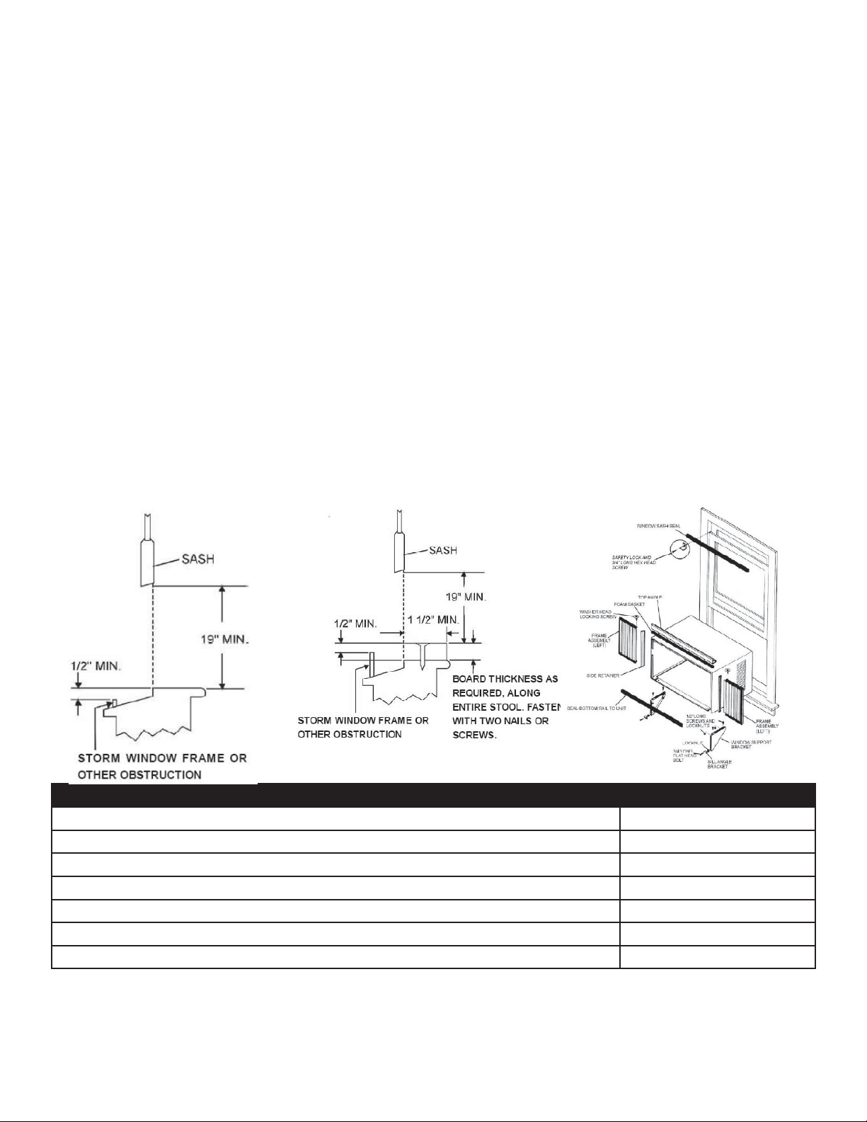
Check window opening size - the mounting parts furnished with this air conditioner are made to
1.
install in a wooden sill double-hung window. The standard parts are for a window opening of
26.5” (673mm) minimum to 40.5” (1029mm) maximum width for the 15-18K and 31” (711mm)
minimum to 42” (1067mm) maximum width for the 25K. Open sash to a minimum of 19”
(483mm).
Check condition of window - all wood parts of window must be in good shape and able to fi rmly
2.
hold the needed screws. If not, make repairs before installing unit.
Check your storm windows - if your storm window frame does not allow the clearance required,
3.
correct by adding a piece of wood or by removing the storm window while the air conditioner is
installed.
Check for anything that could block airfl ow - check area outside of window for things such as
4.
shrubs, trees, or awnings. Inside, be sure furniture, drapes, or blinds will not stop proper air fl ow.
Check the available electric service - power supply must be the same as that shown on the unit serial
5.
plate. Power cord is 48” long.
Carefully unpack the air conditioner - remove all packaging materials. Protect fl oor or carpet from
6.
damage. Two people should move the unit and install.
HARDWARE QTY.
Washer Head Locking Screw for window panels 2
3/4” Long Hex- head Screw 3
Safety Lock 1
1/2” Long Screw and Locknut 4 ea.
3/4” Long Flat Head Bolt and Locknut 2 ea.
Sill Angle Bracket 2
Long Hex-head Locking Screw for top angle, side retainer 5/16” long 10
Tools needed: a large fl at blade screwdriver, tape measure, adjustable wrench or pliers, pencil, level,
socket wrenches, Phillips screwdriver
2
Page 3
WINDOW INSTALLATION
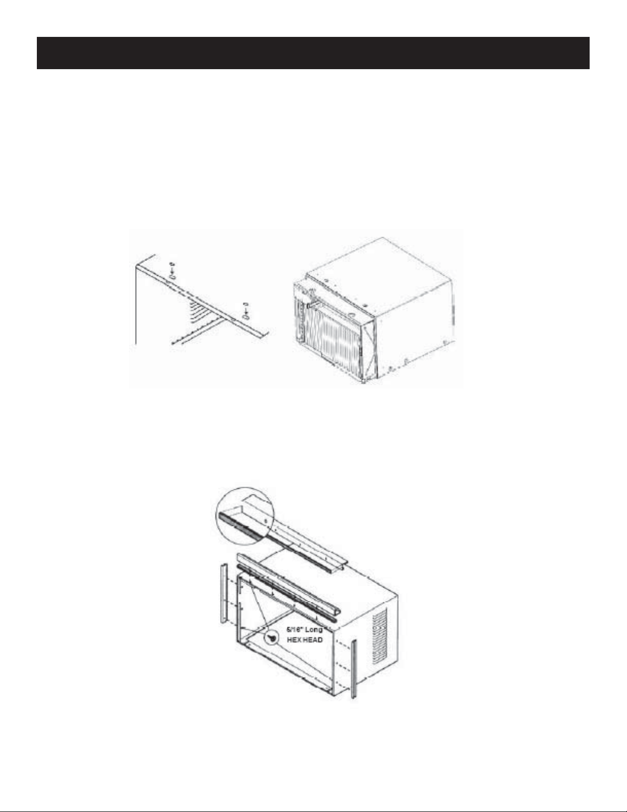
REMOVE CHASSIS
To slide chassis from the cabinet, fi rst remove the two screws on top of the cabinet, hold the cabinet while
1.
pulling on the strap/handle provided at the front of the unit. At the same time, push with thumbs against the
top front edge of sleeve.
Add the two short seals to cover the holes where retaining screws were.
2.
Note: Do not use strap for lifting unit. It is for sliding the chassis within the cabinet only. Be careful of sharp
edges on coil fi ns.
INST ALL TOP ANGLE AND SIDE BRACKET
Attach foam gasket to top angle above holes.
1.
Install top angle and side retainers to cabinet.
2.
3
Page 4

WINDOW INSTALLATION (cont’d)
ASSEMBLE WINDOW FILLER PANELS
Place air conditioner on the fl oor or a bench or table.
1.
Slide “I” section of window fi ller panel into side retainer on the side of the cabinet. Do this to both sides.
2.
Insert top and bottom legs of window fi ller panel frame into channel in the top angel and bottom rail. Do to
3.
both sides.
Insert washer head locking screws (2) into holes in top leg of fi ller panel frame. Do not totally tighten.
4.
Allow leg to slide freely. Screws will be tightened later.
PLACE CABINET IN WINDOW
Open window and mark center of window stool.
1.
Place cabinet in window with bottom stool angle fi rmly seated over window stool. Bring window down
2.
temporarily behind top angle to hold cabinet in place.
Shift cabinet left or right as needed to line up center of cabinet on center line marked on stool.
3.
Fasten cabinet stool with two screws into holes.
4.
Add bottom rail seal over screws to window stool.
5.
4
Page 5

WINDOW INSTALLATION (cont’d)
INSTALL SUPPORT BRACKET
Hold each support bracket fl ush against outside of sill and tight to the bottom of the cabinet. Mark brackets
1.
at top level of sill and remove.
Assemble sill angle bracket to support brackets at the marked position. Hand tighten, but allow for any
2.
changes later.
Install support brackets (with sill angle brackets attached) to correct hole in bottom of cabinet.
3.
Tighten all six bolts securely.
4.
EXTEND WINDOW FILLER PANELS
Carefully raise window to expose fi ller panel locking screws. Loosen screws so fi ller panels slide easily.
1.
Extend panels to fi ll window opening completely. Tighten locking screws on top.
2.
Close window behind top angle.
3.
5
Page 6

WINDOW INSTALLATION (cont’d)
INSTALL WINDOW LOCK AND SEAL SASH
Trim sash seal to fi t window width. Insert into space between upper and lower sashed.
1.
Attach right angle safety lock.
2.
INSTALL CHASSIS INTO CABINET AND INSTALL FRONT TO UNIT
Lift chassis and carefully slide it into installed cabinet.
1.
CAUTION: Do not push on controls or fi nned coils.
2.
Be sure chassis is fi rmly seated towards rear of cabinet.
3.
Refer to User’s Manual for front installation.
4.
6
Page 7

THROUGH-THE-WALL INSTALLATION
SELECT WALL LOCA TION
This air conditioner has a slide out chassis, so it can be installed through an outside wall up to 12” thick.
IMPORTANT: Side louvers must never be blocked.
Notes: All parts needed for through-the-wall installation are provided except a wood frame, shims, and 10
wooded screws (#10 1” long minimum). Select a wall surface that:
does not support major structural loads such as the frame construction at ends of windows and under truss-
1.
bearing points, etc.
does not have plumbing or wiring inside.
2.
is near existing electrical outlets or where another outlet can be installed.
3.
faces and is blocking the area being cooled.
4.
allows unblocked airfl ow from rear sides and end (outside) of installed air conditioner.
5.
PREPARE WALL
Prepare wall in frame construction (including brick and stucco veneer). Working from inside the room, fi nd
1.
wall stud nearest to the center of the area where the air conditioner will be installed (by sounding wall or
magnetically fi nding nails).
Cut or knock out a hole on each side of the center stud.
2.
For the 25K: For the 15-18K:
Measure between the inside edges of every other
3. Measure between the inside edges of every other
stud. Carefully measure and cut an opening
26.75”W (67.9cm) plus twice the thickness of
the frame by 18.9”H (47.9cm) plus twice the
thickness of the framing material used.
Build a wooden sleeve with the INSIDE
4. Build a wooden sleeve with the INSIDE
dimensions of 26.75”H (67.9cm) by 18.9”H
(47.9cm). Frame depth should be the same as
wall thickness. Fill in the space from the opening
to the studs with wood spacers.
Nail the frame to spacers with front fl ush to drywall.
5.
3.
stud. Carefully measure and cut an opening
23.8”H (60.6cm) plus twice the thickness of the
frame by 18”H (45.7cm) plus twice the thickness
of the framing material used.
4.
dimensions of 23.8”H (60.6cm) by 18”H
(45.7cm). Frame depth should be the same as
wall thickness. Fill in the space from the opening
to the studs with wood spacers.
7
Page 8

THROUGH-THE-WALL INSTALLATION (cont’d)
PREPARE AND INSTALL CABINET
Slide chassis from cabinet.
1.
Place cabinet into opening with the bottom rail resting fi rmly on the bottom board of the wooden frame.
2.
Position cabinet to achieve a proper slope for water removal.
3.
Secure the bottom rail to the wooden frame with two large wood screws 1” (2.5cm) long using the two holes
4.
in the bottom of the channel resting on the frame. Support brackets may be used. Installation brackets are
recommended for walls under 5” thick.
Screw or nail cabinet wooden frame using shims in the frame is oversized to eliminate distortion.
5.
Install chassis into cabinet. Caulking and installation of trim on interior wall may be done. You can buy
6.
wood for your local lumber or hardware supply store. On the outside, caulk openings around the top and
sides of cabinet and all sides of the wood sleeve to the opening.
MASONRY INSTALLATION
PREPARE AND INSTALL CABINET
Cut or build a wall opening in the masonry wall similar to the frame construction.
1.
Secure cabinet in place using masonry nails or the right masonry anchor screws.
2.
Install a lintel to support the masonry wall about the cabinet. Existing holes in the cabinet can be used and/
3.
or additional holes can be drilled to fasten the cabinet at various positions. Be sure the side louvers have
clearance space.
Install exterior cabinet support brackets. Caulk or fl ash if needed to provide a weather-tight seal around the
4.
top and sides of cabinet.
To complete installation, apply wood trim molding around room side projection of cabinet.
5.
8
Page 9

© 2006 Sunbeam Products, Inc. doing business as Jarden Consumer Solutions. All rights reserved.
Sunbeam
®
is a registered trademark of Sunbeam Products, Inc. used under license.
Distributed by Petters Consumer Brands, LLC. 4400 Baker Road, Minnetonka, MN 55343.
For service, support and warranty information, visit www.sunbeammajorappliances.com or in the US call 1-866-866-6283.
 Loading...