

SUNBA Network Series User Manual
Dedicated PTZ Camera Professional
2017/04
Version 4.0
SUNBA® PTZ Camera
Network
User Guide V4.0
Series
Please go to http://guide.sunba.net to access the step by step
YouTube video tutorials for Sunba IP PTZ camera setup.
- 01 -
FCC Warning (U.S.A)
MENU
The device has been tested in compliance with limits set by Part 15 of
Federal Communication Commission (Class B). The operation of the
device is thus limited by the following two conditions:
1) it is not permitted to cause harmful interference to any authorized radio
communications, and 2) it must accept any interference it receives.
WARNING: Please test the camera locally by directly
connecting to the default power adapter from the package
before mounting it outside. Stay at least 24 hours to test both
daytime and night vision IR LED.
1. Camera Connection
2. How to Power the Camera
3. Software Package
4. Camera Network Conguration
5. Camera Management by Computer
6. Camera Management by Smartphone
7. Preset, Patrol & Pattern
8. The Full Preset List
9. Camera On-Screen-Display Menu
10. Camera Conguration
11. Camera Infrared and Night Vision
12. Account Management
13. Motion Detection
14. FTP Communication
15. Reset the Camera
16. Cable Waterproof Measures
17. Warranty
02
04
05
06
09
11
14
15
16
18
21
23
24
24
26
27
27

- 02 -
Phase 1: Bench Test
What are you testing in this stage?
Non-PoE camera
PoE+ camera
How to Test Locally
1. Camera Connection
Note PTZ dome cameras have much higher power requirements than
bullet cameras, especially for ones with higher zoom-in capacity. Therefore,
how the unit is powered can be critical to its functionality. Please directly
apply the DC12V adapter on the camera to make sure the unit itself is
working, and try eliminating all cabling factors to set up the bench test.
A default adapter is prepared for you to rule out any problems of the cam-
-era. If the camera works properly under the DC power adapter but not
with PoE, please check the PoE switch/injector you are using or replace an
Ethernet cable.
In short, in a bench test, do NOT use any power extension cable. Please
connect the camera directly to the power adapter. Secondly, if the camera
cannot be found by connecting to the router, please try connecting it to
the Ethernet port on the computer.
ALWAYS test and setup locally before mounting outside!
Adapter
DC12V
192.168.1.*
192.168.1.*
192.168.1.10
- 03 -
Why Test Locally
The reason you should NOT extend the power cable during the bench test
is because DC power drops quickly along the transmission. A bench test
helps you rule out all problems caused by power supply. Underpower cau-
-ses problems such as 1) ickering screen 2) unstable infrared (camera
reboots repeatedly) and 3) spinning dome.
When powered up, the speed dome automatically begins a self-diagnostic
process during which the camera will pan horizontally and vertically to
make sure PTZ, lens and other parts of the camera are functional. Please
contact our technical staff if a self-test does not happen on your unit. Ple-
-ase refrain from disassembling the unit before contacting us. Thanks for
your cooperation.
Questions? Ask support@sunba.net
Built-in self-test
Connection Good
Power Good
Video and Control Good
Tested Day and Night
Guess we are ready to mount it outside.
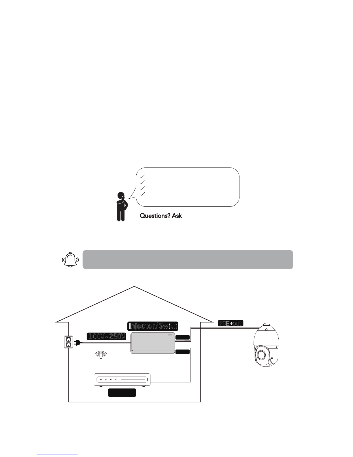
Phase 2: Mounting Outdoor
Good, the camera is working correctly. Now I just need to pick the right
extension cable and mount it outside!
≥30W
100V~250V
Data out
Data in
Router
POE+out
POE+
802.3at
100~250ft
POE+
ELV (Extra-LowVoltageSystem)
Wiring method:
Injector/Swith
- 04 -
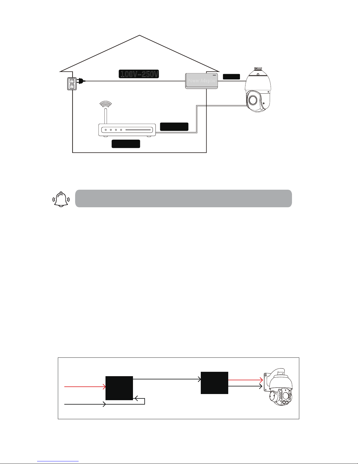
100V~250V
Data in
Router
Non-PoE
ELE (Force Electricity)
Wiring method:
Extended AC Line
DC 12V
Power Adapter
2.How to power the camera
There is an old saying that PTZ cameras are POWER-ful. So do NOT pull the
old setup from your bullet and apply it directly to your new PTZ.
2.1 For Non-PoE Camera (if you extend the power):
The camera may not work properly if the power reaches the camera is be-
-low 12V due to resistance along the extended DC line (distance depend-
-ent). If that happens, please make your AC power source near the camera,
and connect it with our default adapter you received from the package.
For extension, you can select from AC power extension cable (no distance
limit) or thick (≥18 AWG) DC power extension cable.
Risk Relevant
1.Using 24VAC or higher voltage adapter (16V, 24V) will immediately dam-
-age the camera and void the warranty.
2.The camera will be exposed to high risks of motherboard damage and
void the warranty if you use passive PoE injector/splitter.
AC110-220V in
802.3at ≥30W
RJ45 in
48V 0.5A DC out
PoE (cat5/5e/6)
DC12V out
RJ45 out
Active
PoE injector
Active
PoE splitter
Active PoE Injector/Splitter are allowed if you use PoE to power non-PoE camera.

- 05 -
2.2 For PoE+ Camera :
PoE+ IEEE 802.3at standard is required, Note traditional PoE system( 802.
3af standard) delivers up to 15.4W, which is unable to fully support the
camera. Dome cameras, especially with 20 times zoom-in capacity, have
higher power requirements than bullet cameras or xed lens cameras.
The PoE+ switch/injector need to meet two key features:
1. 802.3at. 2. Delivers at least 30w to the single port you are using.
Transmission distance
PoE will also drop power along the Ethernet cable. If you are using a 300
ft long Ethernet cable, you may be at risk. Please try using the Ethernet
cable less than 250 ft. The maximum travel distance also depends on the
quality of the cable and the maximum power supplied by switch/injector.
NVR’s built-in PoE
Some NVR has built-in PoE+ switch. However, this is mostly for devices fr-
-om the same manufacturer as the NVR (examples such as Dahua and Hik-
-vision). The built-in switch may work for few third party cameras but not all.
We thus recommend getting a separate and dedicated PoE+ switch/injector.
Biggest issue when underpower
In the daytime, even 802.3af (conventional PoE system) can provide enou-
-gh power to the camera. However, in the night time, if you are underpower,
the following nightmare begins: low light environment detected -> infrared
on -> not enough power -> reboot -> low light environment detected ->
infrared on -> not enough power -> reboot …… (cycling)
3.Software Package
1. Visit: http://www.sunba.net/en/download/
2. Select one of the web-drives.
3. Go to English-> Software and download the specic software you want.
For Setup
Client Software
Web Plugin
(PC)
Re-development
Device Manager
CMS VMS
IEActive netSDK

- 06 -
Router IP is usually the same value as the “gateway” (with few exceptions),
which the camera’s IP will have to match.
Step 1: Understand the Goal of IP Conguration
No matter what IP Camera Management Software you intend to use later,
the rst step is to make sure your router, computer and the IP Camera are
on the same subnet. Being on the same subnet means “the rst three
octets or segments in the IP address are the same.”
For example
4. Camera Network Conguration
You must rst change the camera’s IP to match the IP of your router!
If your router is 10.0.0.1 and your camera is still 192.168.1.10 (default IP)
you will NOT be able to access the camera by typing 192.168.1.10 in the
web address without changing its IP rst.
Welcome to our local network!
√ On the same subnet
10.0.0.1
10.0.0.188
10.0.0.15
You are not a member of our local network family!
X Not on the same subnet
I am not
connecting
you.
10.0.0.1
FIGHTING !
IP address change
10.0.0.15
192.168.1.10
192.168.1.1010.0.0.188
×
√
- 07 -
Step 2: Know the Router IP/Gateway of Your Network
Method 1: Check Bottom of Your Router Sticker
ROUTER
CHECK
THIS
Model :
Power : 12V 1A
Router IP : 192.168.10.1
User ID : admin
Password: admin
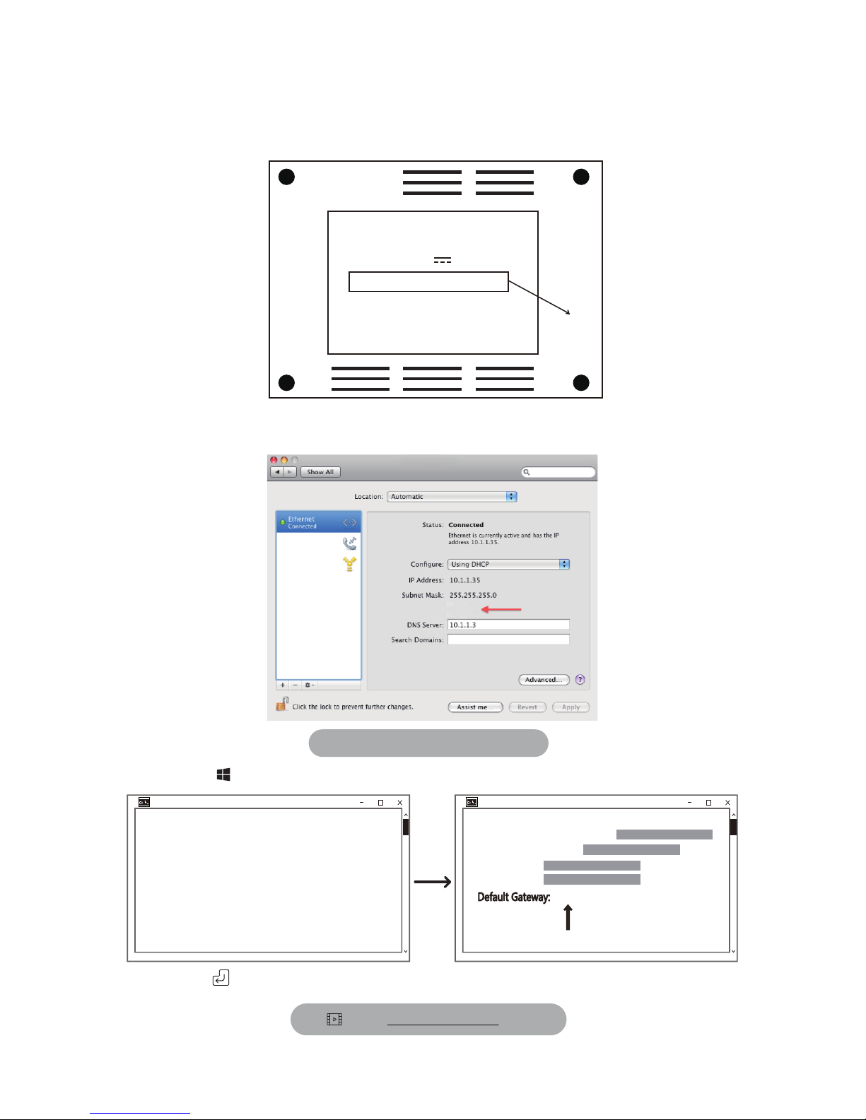
Method 2: Check from your Computer.
Network
Router: 10.1.1.1
MAC :
System Preference->Network
Check gateway.sunba.net for video
PC:
In Start Menu of Windows, type “cmd.exe” and enter ipconfig as follows:
Press enter key and locate the “Default Gateway” from the list:
Command Prompt Command Prompt
Microsoft Windows
(c)2015 Microsoft Corporation. All rights reseved.
C:\Users\Administrator>ipconfig
Ethernet adapter Network Bridge
Connection-specific DNS suffix:
Link-local iPv6 address:
IPV4 address:
Subnet Mask:
Default Gateway:
10.0.0.1
- 08 -
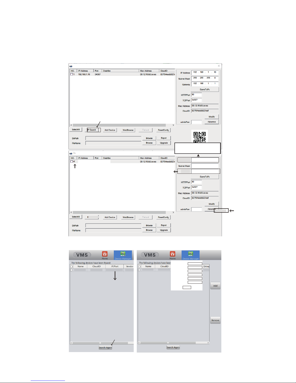
Step 3: Download the IP Cong Tool and Congure the IP address
PC : Please refer to Chapter 3. Software and download “Device Manager”
under English-> Software. Then modify the IP address and Gateway acco-
-rding to what you found from Step 2.
DecviceManager
192.168.1.10 34567
10 . 0 . 0 . 15
10 . 0 . 0 . 1
255 . 255 . 255 . 0
Change to what you found
in step 2.
Gateway
IP Address
DeviceManager
Do NOT change TCP Port or HTTP Port to 554
or 8899, which will conict with the RTSP and
ONVIF port of the camera and lock the device.
No same value for two different ports.
IP Search
Modify
192.168.1.10 192.168.1.10:34667
Sunba
Not Available
192.168.1.10 192.168.1.10:34667
Sunba
IP
Port
Submask
Gateway
UserName
Password
Defa...
Not Available
Change gateway and IP correspondingly
to match your network.
Double Click
10 . 0 . 0 .15
10 . 0 . 0 .1
34567
admin
255.255.255.0
OK
MAC: Please refer to Chapter 3. to download VMS for Mac under English-> Software.
The rst 3 segments should
match the new gateway .
 Loading...