

May 2013
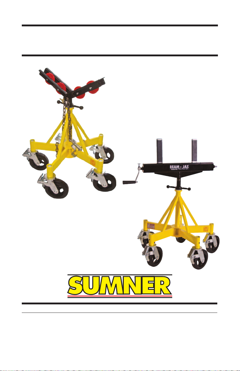
OPERATOR’S SAFETY MANUAL
Sumner max Jax / Beam Jax
7514 Alabonson Road
Houston, TX 77088 U.S.A
ph: 281.999.6900
fax: 281.999.6966
www.sumner.com
75 Saltsman Drive
Unit 5
Cambridge, ON N3H 4R7 Canada
ph: 519.653.5300
fax: 519-653-5305
Unit 16A
Blackpole Trading Estate East
Blackpole Road
Worcester WR3 8SG, U.K.
ph: (44) 01905 458333
fax: (44) 01905 458222
Owner’s
Reponsibilities
NOTICE: Throughout this publication, the words
WARNING, CAUTION, and IMPORTANT
will be used to alert the user to special
instructions concerning a particular
operation that may be hazardous if
performed incorrectly or carelessly.
OBSERVE THEM CAREFULLY!
These “Safety Alerts” alone cannot eliminate the
hazards that they signal. Strict compliance to these
special instructions while performing the service plus
“common sense” operation are major accident
prevention measures.
WARNING Hazards or unsafe practices which
could result in severe personal
injury or death.
CAUTION Hazards or unsafe practices which
could result in minor personal injury, product or property damage.
IMPORTANT Indicates information or instruc-
tions that are necessary for proper
operation and/or maintenance.
Copyright © 2013 by Sumner Manufacturing Co., Inc. All rights reserved. No part of
this book may be reproduced or utilized in any form or by any means, electronic or
mechanical, including photocopying, recording or by any information storage and
retrieval system, without permission in writing from Sumner Manufacturing Co., Inc.,
7514 Alabonson Road, Houston, TX 77088.

Max Jax / Beam Jax Operator's Manual 3
Operator Safety Instructions
Sumner’s Beam Jax and Max Jax mobile stands enable users to easily and safely move beams or pipes weighing up to
2,500 lbs (1,135 kg).
Beam Jax may be used with beams up to 24" wide.
Max Jax may be used with a pipes between 4" and 36" in
diameter.
To operate stands safely requires dexterity, mechanical skills
and sound safety habits
Although Sumner Max and Beam Jax’s are manufactured
for safe, dependable operation, it is impossible to anticipate
those combinations of circumstances which could result in
an accident. The following instructions are recommended for
safe operation of this unit:
1. Read and understand the instructions for safe
operation. Before working with a Sumner jack, understand the correct operation, applications and limitations.
Always contact Sumner when in doubt. Be particularly
aware of specic hazards. Store this safety manual in a
clean area and always at a readily available location.
Additional copies are available for download from
www.sumner.com.
2. Inspect the equipment. Prior to using Sumner jacks,
check all parts to ensure that they are in proper operating
condition. Inspect legs for bends, breaks or metal
deformation.
4 Max Jax / Beam Jax Operator's Manual
CAUTION IN THE EVENT OF ANY BENDS,
BREAKS, OR METAL DEFORMATION TO THE STANDS, DISCONTINUE USE IMMEDIATELY AND
MAKE ANY NECESSARY
REPAIRS/REPLACEMENTS
BEFORE USE.
3. Wear proper clothing. Hard hat or welding helmet,
safety shoes and welding gloves should be worn as a
precaution while operating this stand.
4. Keep work area clean. Always keep oor in work area
clear of clutter for unobstructed movement around the
stand.
5. Operate from proper position. Keep balance and
proper footing at all times.
6. Keep alert. Avoid horseplay around equipment and keep
bystanders at a safe distance. Do not allow children to
operate jacks and always keep them out of work areas.
Do not ride on stands.
CAUTION Never allow anyone under jack
stand with load.
7. Do not misuse unit. Perform only the functions for which
the jacks are designed. Never attempt to operate the
equipment at more than the recommended capacity.
WARNING Modifying the jack stand can
result in injury or death.
Max Jax / Beam Jax Operator's Manual 5
8. Operate only on level surfaces. Use the jack only on
smooth and level surfaces to avoid tipping and the
possibility of operator injury.
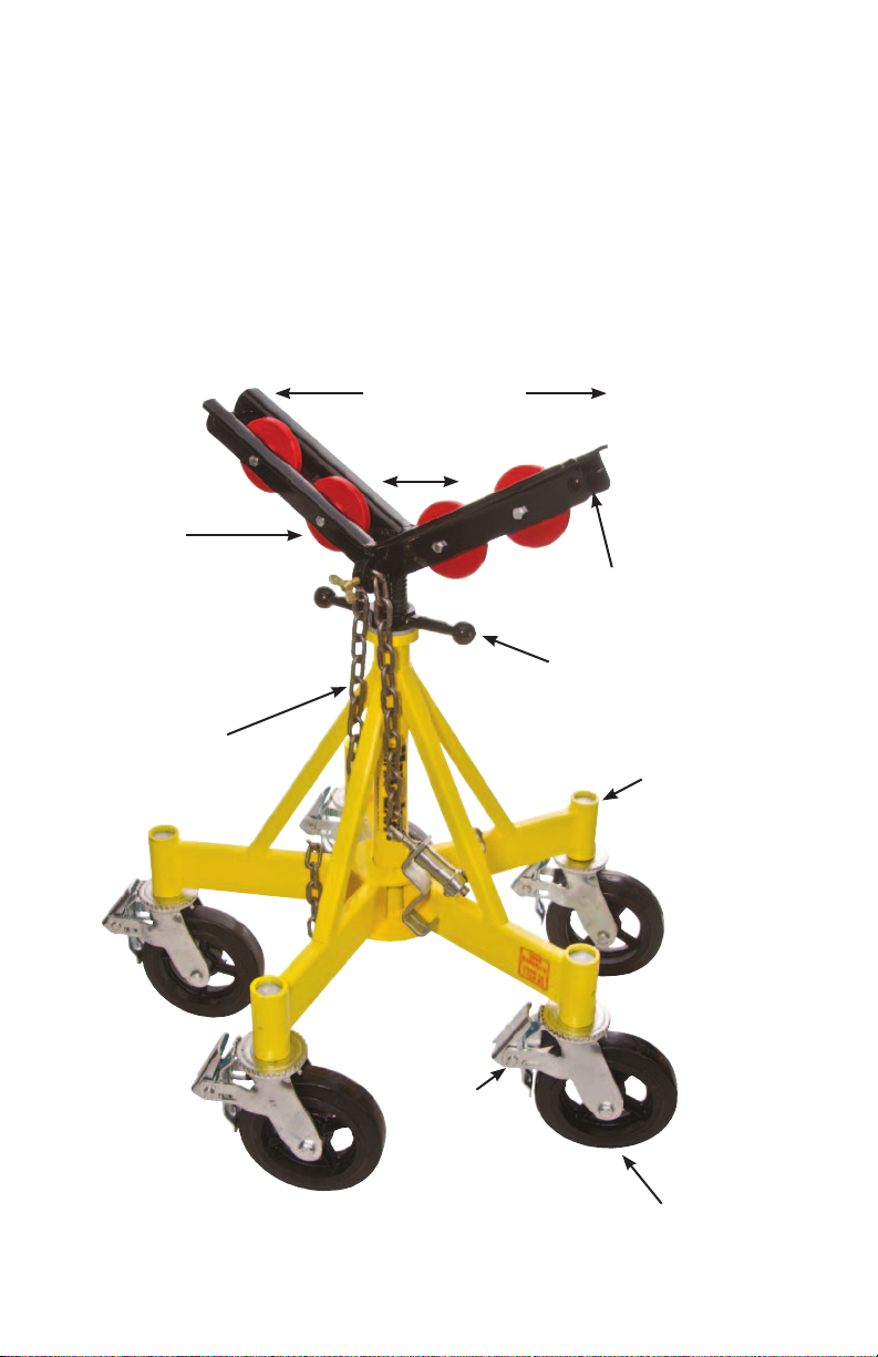
MAX JAX
Maximum
36" (90 cm) pipe
Minimum 4"
(10 cm) pipe
Optional
styles of
roller wheels
Large 12"
(30 cm) vee
Fine adjustment
with bearing
Optional pipe
hold down
chain
Stable and
sturdy 5-leg
construction
Quick
action
brake
Optional, large
8" (20 cm) casters
6 Max Jax / Beam Jax Operator's Manual
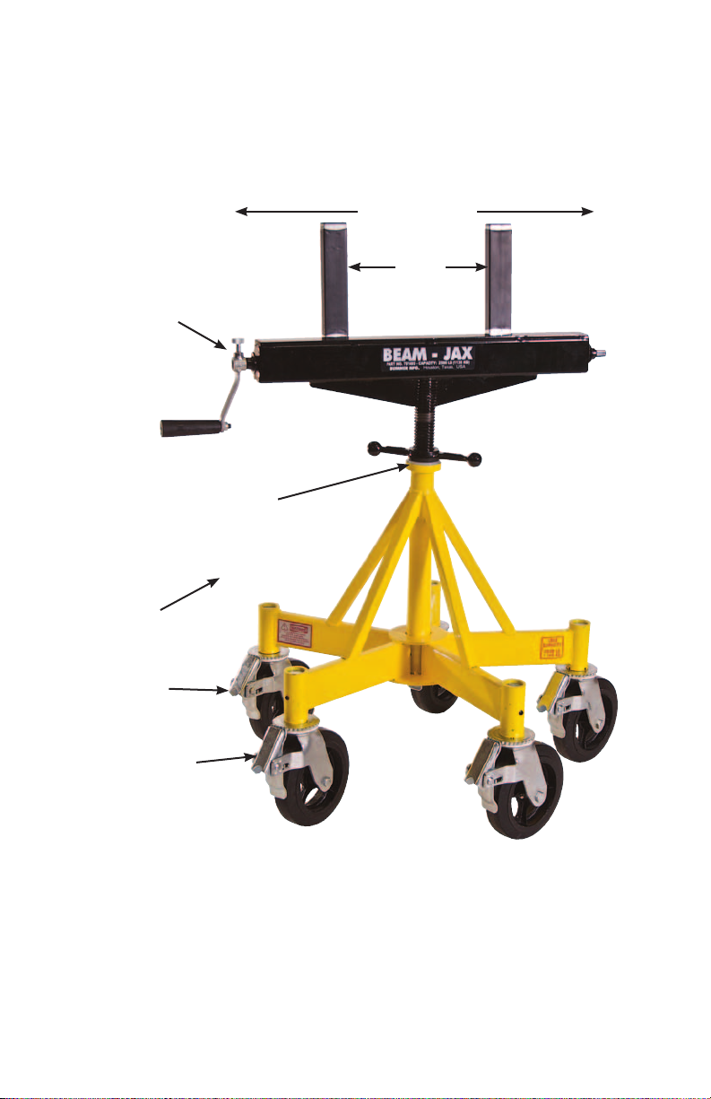
BEAM JAX
Max 24" (61 cm)
Min 0"
(0 cm)
Close or open
clamp from
either side.
Fine adjustment
with bearing
Stable &
sturdy 5-leg
construction
Optional 8"
(20 cm)
casters
Quick action
breaks

Max Jax / Beam Jax Operator's Manual 7
Max/Beam Jax Specications
A
C
B
Specications
Max Jax Beam Jax
Load Capacity 2,500 lb (1135 kg) 2,500 lb (1135 kg)
Basic Unit A (height)
Basic Unit with casters (height)
Beam / Vee Head height C (min.)
Beam / Vee Head height
with casters
B (width)
(width)
(max.)
(min.)
(max.)
27.0" (686 mm)
29.6" (752 mm)
36.5" (927 mm)
39.5 (1003 mm)
21.0" (533 mm)
33.0" (838 mm)
30.5" (775 mm)
42.5" (1080 mm)
B
27.8" (705 mm)
29.6" (752 mm)
37.3" (947 mm)
39.5" (1003 mm)
25.5" (648 mm)
37.5" (953 mm)
35.0" (889 mm)
47.0" (1194 mm)

8 Max Jax / Beam Jax Operator's Manual
Before you start:
1. DO check the load weight to insure that it does not
exceed stand capacity. Additional stands can be used
2. DO inspect stand thoroughly prior to use for evidence of
structural or caster damage
3. DO use the stands on rm, level surface such as pave-
ment or hard ooring
4. DO adjust head with spanner nut to allow for load
height adjustment when leveling
5. DO position heads so that they are approximately the
same height
6. DO locate stands close enough to support load length
7. DO use a minimum of two stands
WARNING Using one stand to support or
brace load can lead to a potential
injury.
8. Do position casters in same direction before placing
load on stand
WARNING Using a hammer to reposition
casters will damage wheels
resulting in injury or death.
9. Do Not lock casters before loading stands
10. Do Not drop loads on stands. Lower loads evenly onto
stands

Max Jax / Beam Jax Operator's Manual 9
General Instructions
Quick action brakes are available on all 5 casters. Use caster brakes when necessary when working on loads to ensure
a stable work surface.
Caster unlocked Caster locked
Beam Jax and Max Jax head heights may be adjusted using
the ne adjustment bearing. Stand heights may be adjusted
quickly before load is placed on stand by lifting the head off
of the base assembly, thus removing the weight of the head,
and adjusting the spanner nut higher or lower on the adjusting screw.
Spanner nut

10 Max Jax / Beam Jax Operator's Manual
Instructions for Moving Load
Max Jax
A. ALWAYS be certain Beam Jax or Max Jax stands are of a similar
height before loading.
ALWAYS be certain to place stands close enough together to t under
the length of the load.
ALWAYS use at least 2 Beam Jax or Max Jax to handle loads. NEV-
ER use a single Beam Jax or Max Jax stand alone to prop up loads.
ALWAYS place loads carefully on Beam Jax or Max Jax. NEVER drop
loads onto Beam Jax or Max Jax stands.
ALWAYS use Beam Jax and Max Jax stands on a rm, level surface
such as pavement or hard ooring. NEVER use Beam Jax and Max
Jax stands on dirt or gravel surfaces.
ALWAYS inspect Beam Jax and Max Jax stands thoroughly before
using for evidence of structural or caster damage including damaged
or bent legs, cracked welds, and cracked, bent or broken casters.
NEVER use a stand that shows signs of structural or caster damage.
IMPORTANT
For more information on general safety
practices and commonly found issues see
Sumner's Pipe Jack Safety Manual.
NEVER lock casters while loading stands.
NEVER load more than one beam or pipe on stands.

Max Jax / Beam Jax Operator's Manual 11
Hold Down Device Instructions:
1. Insert chain end of hold down device through containment loop and tighten set screw to half the length of
chain
2. Back off adjustment screw in order to have maximum
thread travel

12 Max Jax / Beam Jax Operator's Manual
3. Insert chain into slot on Hold Down Housing and
tighten adjustment screw.
4. Make sure Hold down device chain is tightly secures
load to vee.
B.Unlock casters' wheel brakes
C. Make sure all casters are in the same direction. If not
move each end of the Max Jax load in a circle to align
casters

Max Jax / Beam Jax Operator's Manual 13
D. Push load from the end where the hold down device has
secured the load to the stand

14 Max Jax / Beam Jax Operator's Manual
Beam Jax
1. Tighten Beam Jax clamps to the load before moving load
2. Unlock caster wheel brakes
3. Make sure casters are in the same direction. If not, move
each end of the Beam Jax load in circle to align casters.
4. Push the load, do not pull
5. Reposition clamp handles to move out of operator’s way
Accessories:
Base Leg Mounting Pads
Basic Max Jax and Beam Jax come with mounting pads
that insert into the base sockets. Insert pad stem into
the base socket and secure with Allen screw and wrench
provide with the stand.

Max Jax / Beam Jax Operator's Manual 15
Caster stem inserts into base socket and must be secured with the provided Allen screw and wrench

16 Max Jax / Beam Jax Operator's Manual
Max Jax Roller Wheel Options
Instructions: All wheel kits come complete with 4 wheels,
bushing, and fastening hardware. Located on the vee head
are four holes where each wheel is mounted. It is best to
that all attaching bolts be assembled on to the vee in the
same direction.
Pn 781406 Steel wheel roller head kit
Standard roller wheel which comes with Max Jax kit# 1
Pn 781407 Stainless Steel roller head kit
Similar to standard steel wheel but with Stainless contact
Pn 781381 Large Steel roller head kit
Wide surface steel wheel provides more surface contact and
smoother rotation

Max Jax / Beam Jax Operator's Manual 17
PN 781394 Rubber wheel roller head kit
High impact molded plastic/nylon wheels for Stainless and
other exotic metals. Load rating reduced to 1,000lb/ 450 kg.
PN 781382 Stainless Steel Sleeves
Stainless sleeves bolt to the vee head providing complete
stainless surface.
PN 781383 Standard Ball Transfers
PN 781397 SS Steel Ball Transfers
Two ball transfers bolt on to each vee by tighten wing nuts.
Ball transfer can be positioned anywhere on the the vee.

18 Max Jax / Beam Jax Operator's Manual
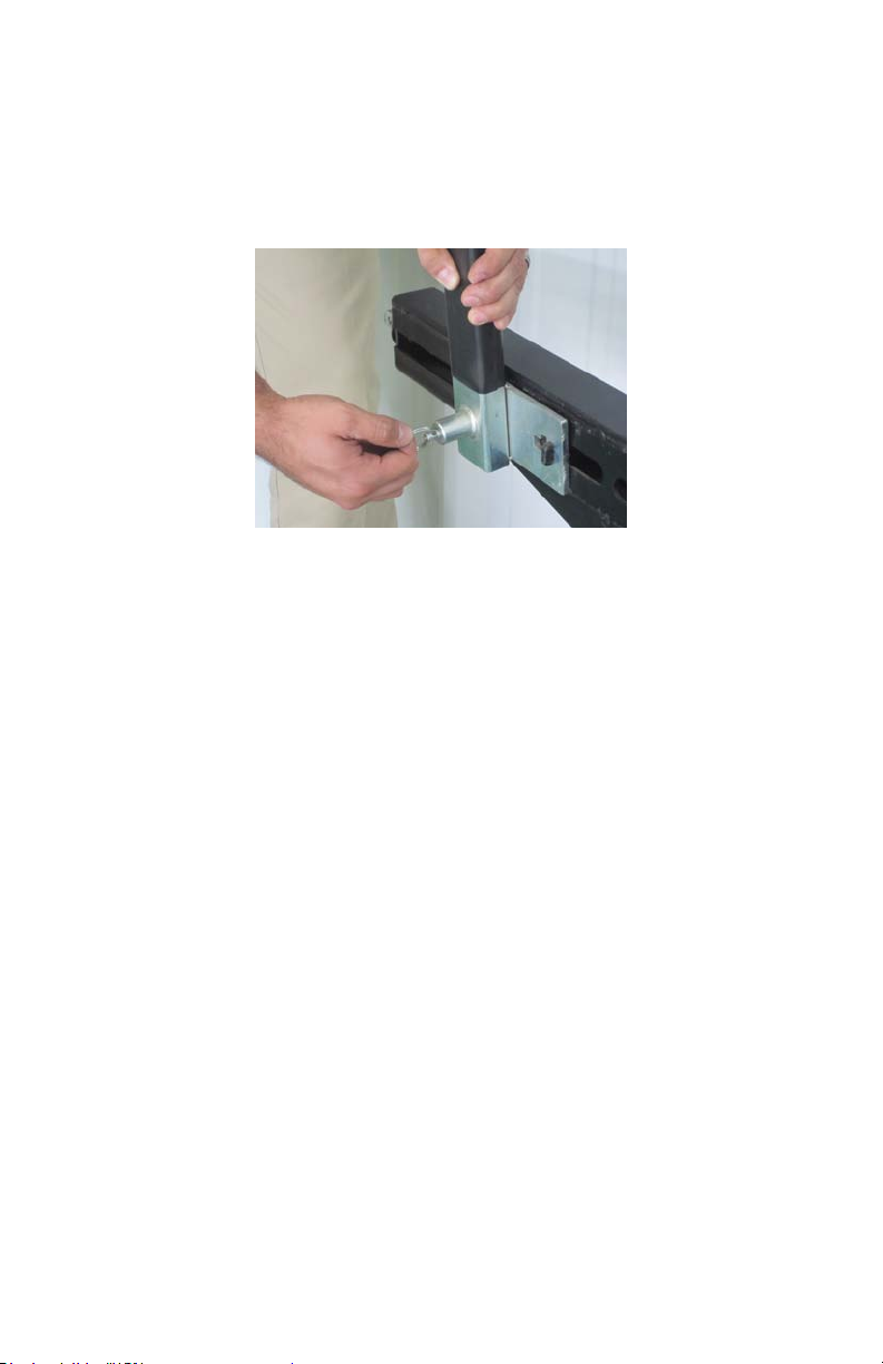
Beam Jax Clamp Adjustment
Adjusting Beam Forks
To remove beam forks, pull out plunging attaching pin and
slide fork assembly.
To clamp narrow width loads, clamp fork should be with
plunger pin nearest to the center of the head.
Max Jax / Beam Jax Operator's Manual 19
To clamp wide loads, plunger pin on the clamp forks should
be positioned out towards the end of the head.

 Loading...