

Page 1
B
p
October 2013
Operator’s Manual
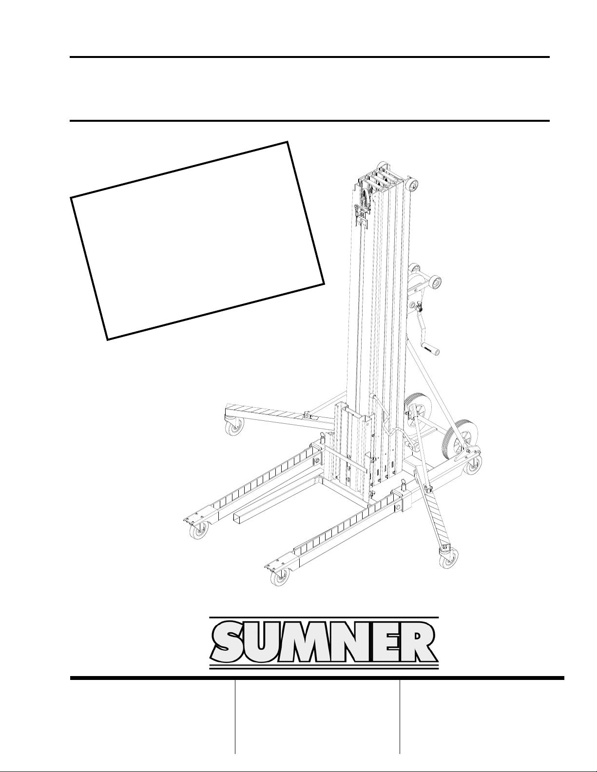
Series 2100 Contractor Lif ts
!
G
N
I
W
p
o
e
r
o
f
e
d
a
e
r
O
e
B
e
t
o
f
i
c
n
d
n
a
a
r
e
p
e
m
o
l
a
i
t
C
h
u
o
y
e
h
u
n
i
t
a
r
r
e
d
n
s
’
r
o
t
a
l
i
m
a
f
d
r
a
z
a
U
S
l
l
a
e
v
a
N
R
A
g
s
M
i
n
a
s
M
s
i
h
t
d
n
a
t
u
n
a
w
r
f
o
E
N
q
y
u
,
t
f
i
l
s
i
h
t
.
l
a
h
t
i
h
t
R
s
e
e
h
t
s
i
i
t
u
o
n
n
.
t
i
.
s
7514 Alabonson Road
US
Houston, TX 77088
phone: 281-999-6900
fax: 281-999-6966
75 Saltsman Drive, Unit 5
Canada
Cambridge, ON N3H 4R7
phone: 519-653-5300
fax: 519-653-5305
UK
Unit 16A
Blackpole Trading Estate East
Blackpole Road
Worchester, WR3 8SG
phone: (44) 01905 458333
fax: (44) 01905 458222
Page 2

Page 3
Index
Owner’s Responsibilities........................................................................3
Operator Safety Instructions..................................................................4
Inspect the Equipment....................................................................4
Work Area Hazards.........................................................................5
Operating Procedure...........................................................................5-9
Unpacking the Lift........................................................................5-6
Moving Lift (no Load)......................................................................6
Moving Lift (with Load) ................................................................... 6
Reversing the Forks........................................................................7
Lifting and Lowering Loads.............................................................7
Using the Stabilizer Legs.............................................................7-8
Folding the Base Legs....................................................................8
Storing the Forks..........................................................................8-9
Loading into Vans/Trucks ...............................................................9
Mast Hold Down Bar.......................................................................9
Options............................................................................................10-11
Safety Brakes................................................................................10
Fork Extensions............................................................................10
Boom........................................................................................10-11
Specifications.......................................................................................11
Load Capacity.................................................................................11-12
Lift Diagram..........................................................................................12
Maintenance Instructions................................................................13-14
Troubleshooting ..............................................................................14-15
Maintenance Record............................................................................16
OWNER’S RESPONSIBILITIES
Throughout this publication, the words WARNING, CAUTION
and IMPORTANT will be used to alert the user to special
instructions concerning a particular operation that may be
hazardous if performed incorrectly or carelessly.
OBSERVE THEM CAREFULLY !!
WARNING Hazards or unsafe practices which
!
!
could result in severe personal injury or
death.
CAUTION Hazards or unsafe practices which
could result in minor personal injury,
product or property damage.
IMPORTANT Indicates information or instructions
that are necessary for proper
operation and/or maintenance.
3
Page 4
OPERATOR SAFETY INSTRUCTIONS
IMPORTANT
Read and understand this instruction manual prior to
operating or performing maintenance on this lift!
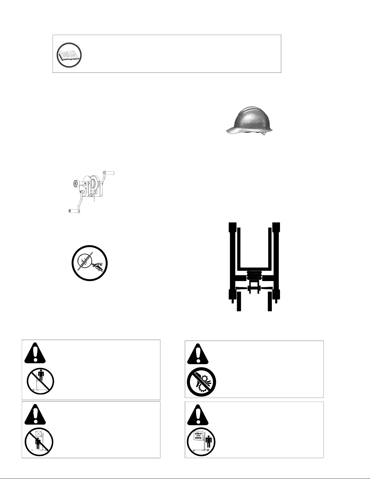
1. Inspect the Equipment
Prior to each use of the unit, check all moving
parts and wire rope to ensure that they are in
proper operating condition.
If a unit has visible damage or does not transfer
up and down smoothly during pre-operation, do
not use the unit.
Wire rope (cable) must have a minimum of four
complete wraps around the winch drum.
If cable is kinked, worn, frayed, damaged, or has
anything on it that would obstruct its rotation
around the pulley wheels, do not use the unit!
Wear proper clothing. Hard hat, safety shoes, and
gloves should be worn as a precaution while
operating this lift.
Avoid horseplay around equipment, and keep bystanders at a safe distance. Do not allow children
to operate this unit and always keep them out of
work areas.
Operate from the proper position. Keep your
balance and proper footing at all times.
FRONT
RIGHT LEFT
Use only factory replacement parts. Anything
else will severely compromise the quality and
safety designed into this lift.
Each unit should have a complete set of decals
and a legible Operators Manual. Contact
distributor if any of these items are missing.
WARNING
No riders are allowed on this lift.
This is not a personnel lift and
never should be used for hoisting
or moving people.
WARNING
NEVER ALLOW ANYONE TO
STAND UNDER AN ELEVATED
LOAD.
OPERATOR
POSITION
WARNING
KEEP HANDS AWAY FROM
ALL MOVING PARTS WHILE
OPERATING UNIT.
WARNING
DO NOT EXCEED RATED
CAPACITY
4
Page 5
OPERATOR SAFETY INSTRUCTIONS
(cont’d)
Do not misuse the unit. Perform only the functions
for which the unit is designed. Never attempt to
operate the equipment at more than the
recommended capacity.
Never use units in tandem to lift a load which
exceeds the capacity of a single lift.
Secure load to prevent it from shifting on forks, and
tie down loads before lifting.
Lock caster brakes when leaving unit unattended.
Keep load at lowest possible position at all times.
2. Work Area Hazards
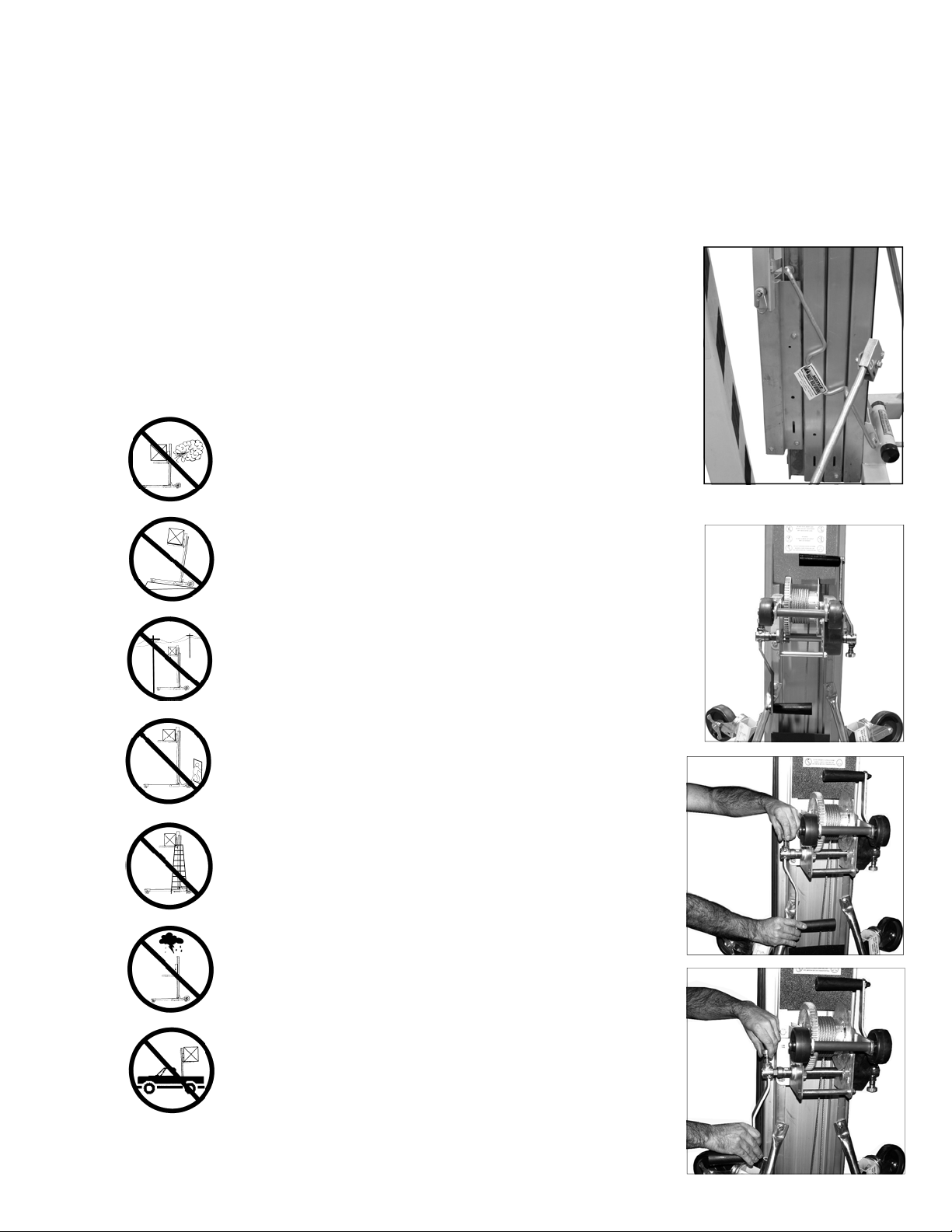
Never operate during high wind
conditions. Lifting bulky loads during
high winds can result in the lift tipping
over and the possibility of operator
injury.
OPERATING PROCEDURE
1. Unpacking the Lift
Remove the lift from the shipping pallet by cutting
the bands and rocking the lift back on the 10”
transportation wheels. Carefully roll the lift back off
of the pallet onto a smooth, level surface. Place the
lift back into it’s upright stored position.
The lift has been shipped
with the Mast Hold Down
Bar engaged. The
purpose of the Mast Hold
Down is to keep the
mast sections from
extending during
transportation. To use
your lift, pull bar toward
you and place back
behind mast sections.
Operate only on level surfaces. Use
the unit on smooth and level surfaces
to avoid unit tipping over and the
possibility of operator injury.
Always watch for and avoid overhead
wires and obstructions when using the
unit or moving unit to and from the job
site.
Keep work area clean. Always keep
work area clear of clutter for
unobstructed movement of the unit.
Never leave elevated load unattended.
Do not use unit to support ladders, for
climbing, hoisting or people moving.
Do not use unit outside in thunder,
lightning, or severe weather.
When a unit has an elevated load, it
can be transported on the unit’s 5”
casters only. Do not operate from an
unstable platform such as the bed of a
truck.
The winch handles have
been placed in the stored
position.
To place the winch
handles in the
operating position, pull
up on the locking pin
and slide the handle
off of the winch shaft.
Rotate the handle
assembly around so
that the black plastic
grip is facing away
from the winch. While
pulling up on the
locking pin, slide the
handle back on to the
winch shaft. Repeat
this procedure for the
other handle.
5
Page 6

OPERATING PROCEDURE (cont’d)
When properly installed,
the winch handles
should be mounted 180
degrees apart, as shown
in the picture. Do not
attempt to raise or lower a load with
the handles mounted in any other
manner.
2. Moving Lift to Work Area
(No Load)
The lift is normally moved to the job site by rolling on
its 10” tires or four caster wheels. Note: Do not pull
by the load lifting cable.
IMPORTANT Before tilting unit to reclined position,
the carriage must be lowered all the way down and
the Carriage Safety Latch must be engaged.
CAUTION
Always use proper lifting techniques.
To Tilt the unit into position for transport; from a
squatting position, grasp the legs just past the
casters and while keeping your back straight, lift upwards to a standing position. The unit is now ready
to transport on its 10” wheels.
If it is necessary to go under a low doorway or
obstruction, the unit may be reclined onto the 3”
wheels located on top of the masts sections and on
the winch.
CAUTION
Never allow anyone to stand
directly behind the mast while
the unit is tilted.
3. Moving Lift in Work Area (With Load)
Although it is best to move the unit to the job site
unloaded, light loads may be transported as long
as the unit is rolled on the four caster wheels and
on a level surface. Always have the load in the
lowest possible position before moving the unit.
should be contained to short distances; i.e.,
If it is necessary to move the unit with an elevated
load:
Make sure the area is clear of obstructions
Keep personnel away from the load and behind
Move the unit slowly, avoiding sudden jerky
Make sure the load is secure and properly
6
CAUTION
If a load is being transported,
it should be secured to the fork
to avoid shifting.
CAUTION
Moving the unit with elevated loads
10-15 feet/4-5 meters.
the operator’s position
starts and stops
balanced. Note load capacity at given centers
on page 11.
WARNING
beyond fork ends by modifying the lift.
Lift may become unstable.
Do not extend load centers
Page 7
OPERATING PROCEDURE (cont’d)
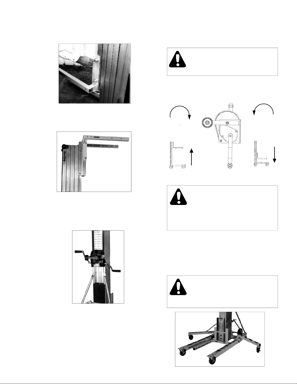
4. Reversing the Forks
Disengage 4 spring-loaded pins. Rotate fork
assembly 180 degrees. Engage 4 spring-loaded
pins.
Reverse step #4 to return the forks to their normal
position.
5. Lifting and Lowering Loads
Use the winch to crank forks up or down into the
desired position. Then crank winch handles up
about 1/4 turn to set the safety brake.
Any unstable load must be balanced and
secured to the forks prior to lifting.
Turn winch crank clockwise to elevate the load,
while watching for overhead obstructions.
CAUTION
Make sure the floor surface is level.
After load is removed from the forks, lower masts
by turning winch crank counter clockwise.
Lifting
Lock caster brakes when leaving unit unattended.
6. Using the Stabilizer Legs
No riders allowed on this unit. This is not a
personnel lift and never should be used for
Use of the stabilizer legs is recommended for all
lifts with loads weighing 400 pounds or more
extended to heights greater than 12 feet, or for
any large, bulky loads.
7
WARNING
hoisting or moving people.
WARNING
Never operate lift during
high wind conditions.
Lowering
Page 8
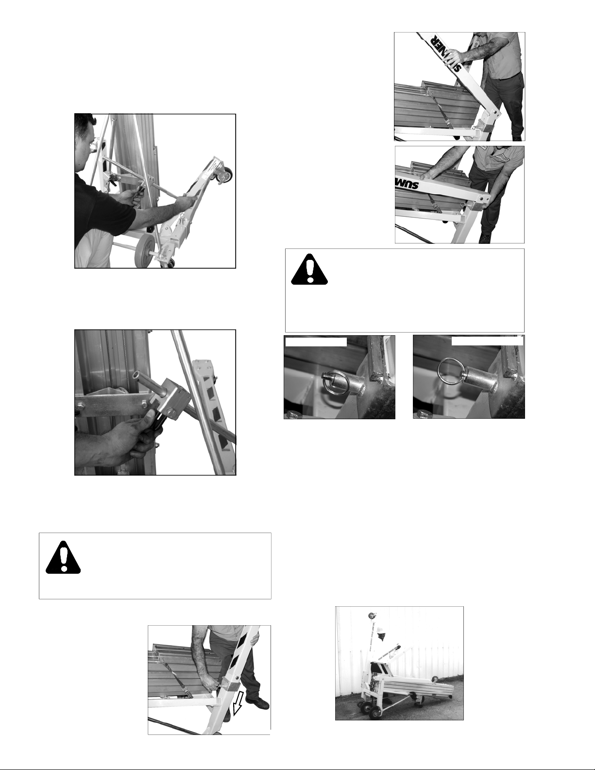
OPERATING PROCEDURE (cont’d)
Position the lift on a level surface. Pinch the stabilizer locking mechanism and pull the stabilizer legs
down until the caster on each leg is snugly on the
floor.
To replace the leg in the stowed position, pinch the
locking mechanism release and fold the leg up.
Fold the leg until it
forms a 90 degree
angle with the base
While holding the leg in
the 90 degree
position, slide the Leg
Lock back towards the
leg until the spring
loaded plunger pin
engages into position.
CAUTION
Never move a lift in the upright
storage position, or in the operating position
unless the spring loaded plunger pins are fully
engaged on both Leg Locks.
7. Folding the Base Legs
Lower the carriage all the way down and engage the
Mast Hold Down Bar.
CAUTION
Do not drop the unit. Lower the unit by
bending your legs, not your back!
Tilt the unit over onto the winch wheels.
Pull out on ring, to disengaged the spring
loaded plunger pin.
While holding onto the
leg, slide the Leg Lock,
down towards the
outrigger mount.
NOT ENGAGED
8. Storing the Forks
Using two hands, pull the lower 2 spring-loaded rings
located above the fork arms and simultaneously rotate
the fork outward.
Again, using two hands, pull the upper 2 springloaded rings located at the top of the fork assembly
and remove the forks from the carriage.
While pulling out on the upper 2 spring-loaded rings,
reposition the upper 2 spring loaded pins so that they
align with the top two holes in the carriage and
release the rings.
Once the pins are locked in the holes, the carriage
can be rotated up into the travel/storage position.
Lift may be stored in the upright, compact position.
8
FULLY ENGAGED
Page 9
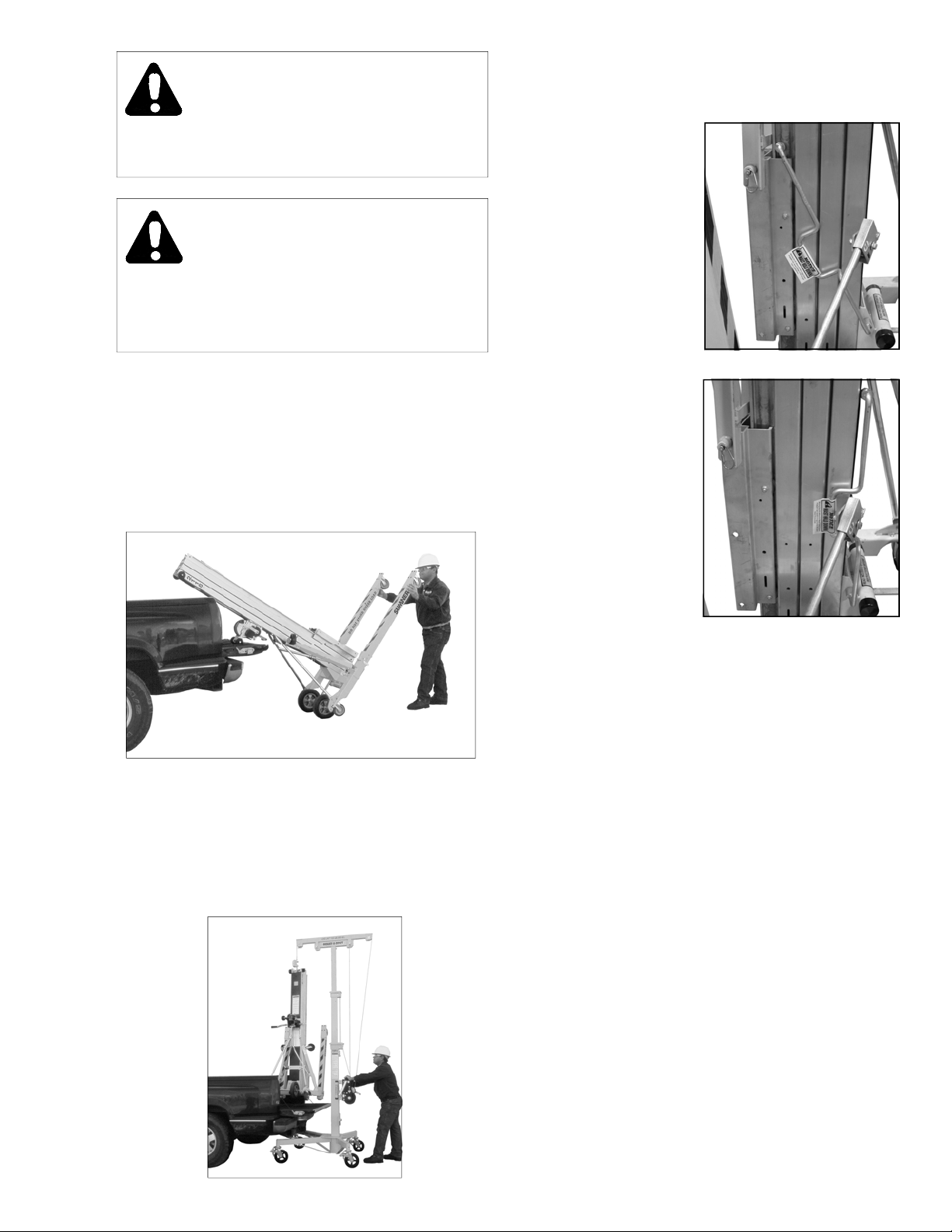
CAUTION
Once the forks are rotated up they must be
secured to prevent them from falling back.
CAUTION
Carriage must be secured with Mast Hold Down.
See Mast Hold Down Bar section on this page.
9. Loading into Vans/Trucks
Fold the base legs and fork assembly (see
instructions above). Tilt the unit back onto the winch
side and slide the masts in first. Lift the base end
and roll the lift on the 3” wheel and 10” transport
wheels. Tie the unit down to prevent movement
during transport.
10. Mast Hold Down Bar
Securing the Carriage:
Lower the carriage all the
way down. With the forks
in place, engage the Mast
Hold Down Bar above the
fork carriage.
To release Hold Down,
pull bar toward you and
place back behind mast
sections.
Unit may be loaded with a crane. Unit must be in
upright and compact position with legs, forks, and
stabilizers securely in their stored positions. If unit
has any loose or unsecured items, remove them.
Attach lifting hook to top roller bar located on top of
bottom mast. Before elevating unit, lifting hook
should always point away from the lift.
9
Page 10
OPTIONS
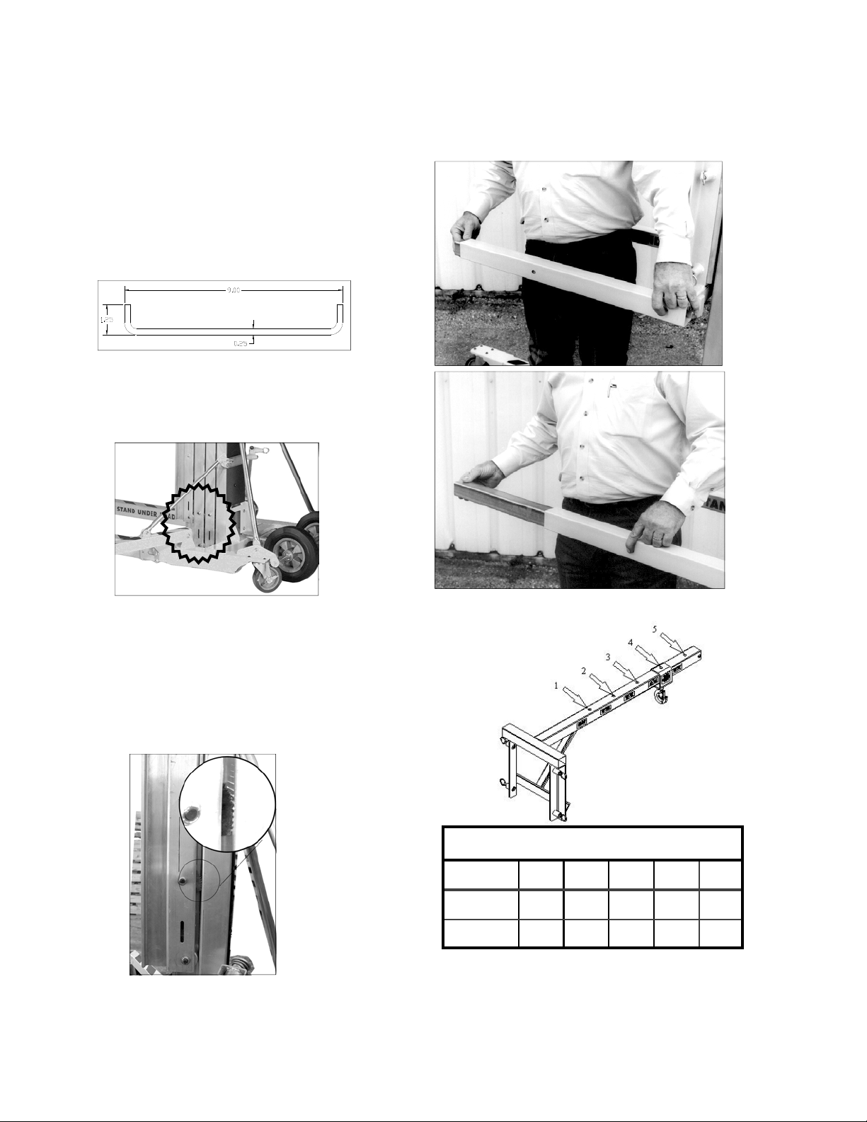
Safety Brakes:
The Safety Brake will automatically engage when the
unit is horizontal, preventing disassembly of the mast
sections. When this occurs, the masts will extend, but
not retract. A special tool, which can be found in the
Operator’s Manual tube, is required to release the
brakes. If the tool is lost or damaged, one can be
made simply from a piece of 1/8 to 1/4 inch diameter
steel rod 9 inches long with both ends bent into an “L”
shape 1-1/4 inches long.
To release the brake, lay the lift back onto the winch
wheels and place the tool into brake access slot
located on the left side of the lift, and through the hole
in the counterweight.
Pull the tool down and the brake will release.
It may be necessary to push the locked mast (or
Carriage) up slightly while pulling down on the tool.
Once the brake is released, maintain pressure on the
tool and slide the mast sections apart.
Repeat this procedure for each mast section.
When the brake is engaged, it will be possible to see
the Brake Cam acting on the adjacent mast section.
Once the brake is released, it will rotate around into
its normal position and will not be visible.
Fork Extensions:
To use fork extension, press plunger on each fork arm
and slide extensions out of tube until plungers lock
into position. Reverse this step to reinsert the
extensions.
Boom:
Station 1 2 3 4 5
Boom Capacity Chart
Lbs. 650 525 425 300 200
Kg. 300 240 195 140 90
To use Boom, pull spring-loaded ring and slide hook
housing to desired station. Release spring-loaded
ring, making sure that the plunger engages into the
locating hole.
10
Page 11
WARNING
Do not use Boom if plunger is not engaged
in the locating hole.
WARNING
Never exceed the rated capacity
at any station. Doing so may cause
the lift to become unstable.
SPECIFICATIONS
Dimensions 2112 2118 2124
Height - stowed 84” 213.4 cm 84” 213.4 cm 84” 213.4 cm
Length - stowed 34” 86.4 cm 34” 86.4 cm 34” 86.4 cm
Height - operating 84” 213.4 cm 84” 213.4 cm 84” 213.4 cm
Length - operating 62” 157.5 cm 73” 185.4 cm 73” 185.4 cm
Base width 31.25” 79.4 cm 31.25” 79.4 cm 31.25” 79.4 cm
Width with stabilizer legs 74” 188.0 cm 74” 188.0 cm 74” 188.0 cm
Ground clearance 2.5” 6.4 cm 2.5” 6.4 cm 2.5” 6.4 cm
Load height (minimum) 6” 15.2 cm 6” 15.2 cm 6” 15.2 cm
Maximum height (forks down) 10’ 11-5/8” 3.3 m 16’ 4-5/8” 5.0 m 21’ 9-5/8” 6.6 m
Maximum height (forks reversed) 12’ 11-3/8” 3.9 m 18’ 4-3/8” 5.6 m 23’ 9-3/8” 7.2 m
Weight
Net weight 255 lbs. 115.9 kg 327 lbs. 148.6 kg 372 lbs. 169.1 kg
Load Capacity
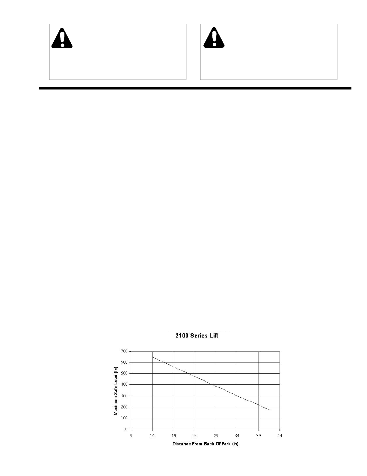
Load capacity, 14” load center 650 lbs. 300 kg 650 lbs. 300 kg 650 lbs. 300 kg
Load capacity with fork extensions
Fork Specifications
Standard fork width 21.5” 54.6 cm 21.5” 54.6 cm 21.5” 54.6 cm
Standard fork length 28” 71.1 cm 28” 71.1 cm 28” 71.1 cm
Fork length with extensions 42” 106.7 cm 42” 106.7 cm 42” 106.7 cm
Fork weight 32 lbs. 14.5 kg 32 lbs. 14.5 kg 32 lbs. 14.5 kg
Fork weight with extensions 38 lbs. 17.3 kg 38 lbs. 17.3 kg 38 lbs. 17.3 kg
200 lbs. 90 kg 200 lbs. 90 kg 200 lbs. 90 kg
LOAD CAPACITY CHART
11
Page 12
FRONT
OPERATOR
POSITION
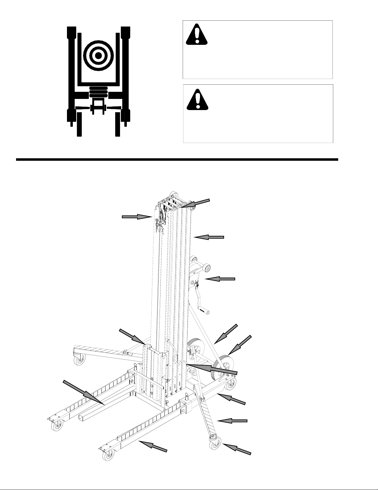
The center of gravity of the load should always
be centered between the fork arms and as far
RIGHT LEFT
The center of gravity of the load should never
extend past 22” on standard forks and
LIFT DIAGRAM
WARNING
back towards the lift as possible.
WARNING
36” on extended forks.
CENTER MAST
CARRIAGE ASSEMBLY
LIFTING FORK
TOP MAST
BOTTOM MAST
WINCH ASSEMBLY
MAST BRACE
10” TRANSPORT
WHEELS
MAST HOLD DOWN
BASE LEGS
12
BASE ASSEMBLY
WITH 5” CASTERS
STABILIZER LEGS
STABILIZER LEG
CASTER
Page 13
MAINTENANCE INSTRUCTIONS
Before each use:
1. Inspect the cable for kinks and frays. If kinked or more
than 3 wire strands are broken (small wires) do not use
the lift until the cable has been replaced.
2. Make certain winch operates freely and cable is not
tangled on the winch drum.
3. Check forks, legs, and base for bends.
4. Make sure caster wheels move freely.
5. Check stabilizer legs by lowering them into normal
operating position to check locking mechanism and
raising them to check for smooth transfer.
Recommended Inspection Every 6 Months:
1. Inspect cable for frays and kinks (see point 1 above)
2. Make certain winch works freely and that there are no
loose or damaged parts.
3. Brake Inspections: Manually raise and support each
movable mast section and carriage a minimum of 6”
above their lowest position. Use a wooden block with a
rope attached to the bottom end to quickly pull on rope to
remove wooden block support from mast sections being
tested. Brakes should engage before mast section
reaches bottom stop. Use winch to crank up mast
sections to release the safety brakes.
Winch Maintenance:
1. Refer to the winch assembly drawings in this Operators
Manual.
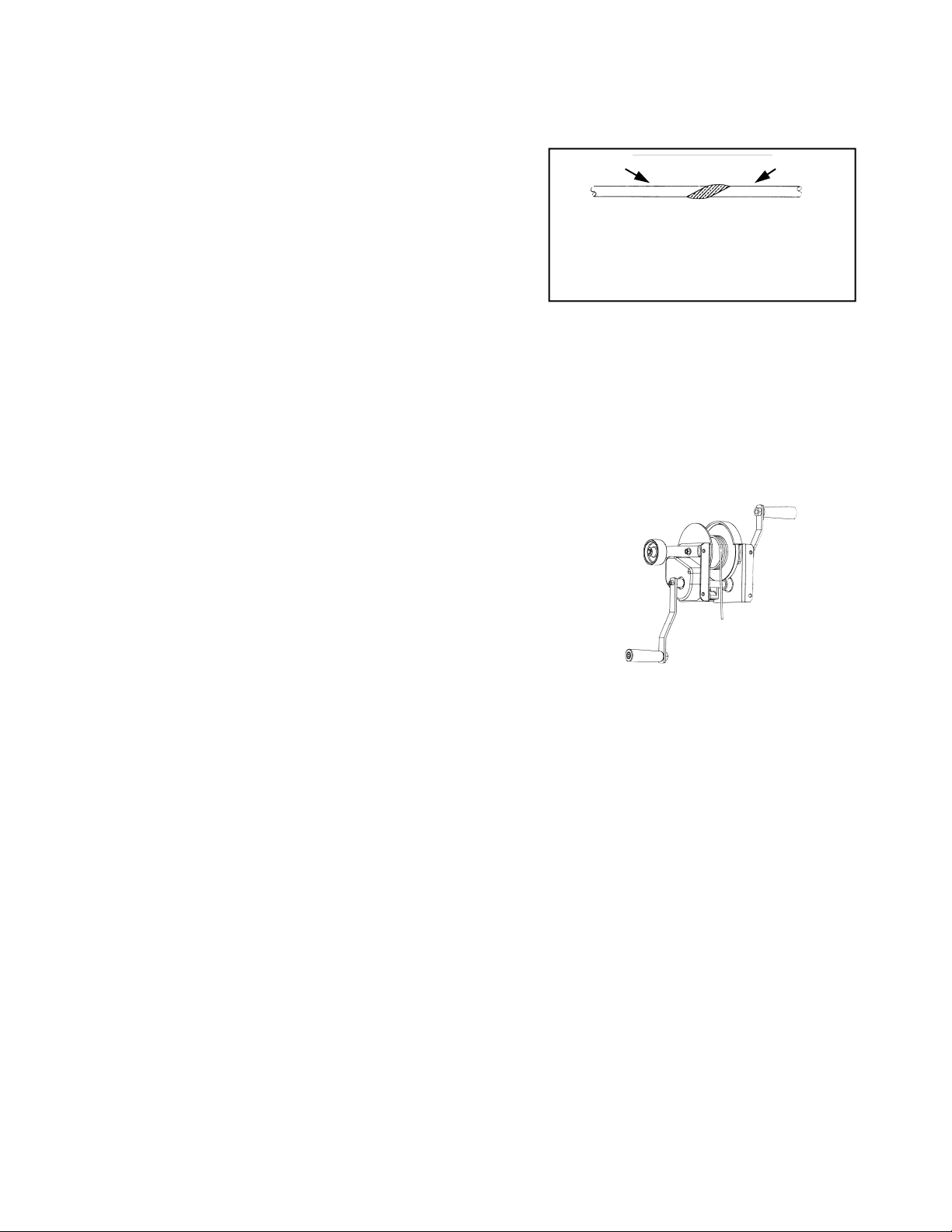
apart approximately 2” from the weld on the new cable
and fuse the end of the new cable to prevent unraveling.
7. Bolt the new cable (looped end) to the top of the top
mast.
8. Unwind the cable from the load drum, loosen the set
9. Thread the plain end of the cable through the drum into
the roper keeper and tighten the set screw. Note: The
cable must be fed from the bottom of the winch
between the winch and the mast sections, over the
drum and into the slot on the wide plate.
old cable new cable
Trim all loose strands before pulling cable
through unit. Make sure that welded area is not
too bulky to pass between the rope guards and
pulley wheels.
screw and remove the cable.
2. Be sure that both winch covers are on the winch.
3. Check ratchet dog and brake ratchet for wear. If any
wear is visible, replace the part. If not, lubricate the holes
in both parts with a light oil.
4. Inspect gear teeth for wear. If there is no sign of visible
wear, brush teeth with 50-wt. Motor oil.
5. For proper brake adjustment see “Troubleshooting”
section on page 14.
Replacing the Cable:
1. Lower the carriage to engage the safety latch.
2. Remove the large gear cover from the winch.
3. Unbolt the cable from the top of the top mast.
4. Cut the looped end off the old cable assembly, using
cable cutters or a cutting torch.
5. Fusion weld the plain end of the new cable to the cut
end of the cable. Note: The fused joint must be
straight and smooth or it will not pass through the
pulley assemblies inside the unit.
6. Use the winch to pull the old cable from the winch side
while feeding the new cable through the carriage until the
old cable is completely out of the unit. Cut the cables
10. Wind the slack cable tightly and evenly across the load
drum.
11. Replace the winch covers.
General Maintenance:
1. Check both winch handles for wear or bends.
2. Inspect 3” roller wheels mounted on the winch and top
3. Examine all bolts and nuts to be sure they are tight.
4. Legs, forks, braces and base should be dent free and
5. Check pulley covers for damage (indentations) which can
6. Make sure load line is seated in all pulleys and that pulley
7. Check stabilizer legs by lowering them into normal
8. Check all roller wheels for free rotation.
9. Inspect masts and carriage hold-down device
mast for damage and smooth rotation.
damage free.
restrict the rotation of the pulleys.
rotates without obstruction.
operating position to check locking mechanism and
raising them to check for smooth transfer.
13
Page 14
10. Raise mast sections to inspect for free, smooth sliding
action. Make sure wire slideways are free of dust and
oxidation and spray a light coat of silicone lubrication in
slideways.
11. Make sure caster wheels and 10” transport wheels
rotate freely and are undamaged.
12. Inspect leg latch mechanism and apply light grease to
spring loaded plunger.
13. Check to be sure that all three mast covers are attached
to the lift.
14. Check the safety brake operation.
[See Safety Brake maintenance on page 10]
WARNING
Replace all worn or damaged parts
only with Sumner parts.
WARNING
Modifying the lift in any way can cause
injury or death!
TROUBLESHOOTING
PROBLEM CAUSE SOLUTION
Masts not rising in succession
Check to make sure that the load does not
exceed the 650 lb/300 kilo load limit
If none of these solutions seem
to fix the problem...
NOTE: Mast sections may rise out of succession when load is near maximum capacity. If this occurs, the
masts will correct themselves during continued use or when the load is removed from the forks. Mo vement
of the mast sections will not affect the position of the forks. The carriage must elevate to the top of the top
mast section before any mast sections begin to rise, and it should lower last.
Mast roller not rotating. Inspect tracks for
debris, grease, or any foreign obstruction
Mast roller tracks are clean and mast
roller wheels are not rotating
Inspect mast sections for damage Replace damaged mast section
Mast sections will not release or transfer
Overloading
Load may not be centered
properly on the forks
Cable pulley wheel not
rotating
Inspect cable for damage If cable is kinked, worn or frayed,
down
Call distributor’s
Remove excess weight
Check load capacity chart and
reposition load
Clean mast sections with a
degreaser or brake cleaner and
lubricate with a silicon lubricant
If there is any damage to the pul-
ley wheel, or if the wheel doesn’t
rotate smoothly, change wheel. If
the rope guard shows any dam-
age, replace it
replace cable
If wheels and mounting hardware
are not damaged, clean wheels
and lubricate shoulder bolt. If the
wheels do not rotate freely, re-
place roller wheel assembly.
Check the safety brake. The
brake will not release unless the
unit is vertical.
Customer Service Department
14
Page 15
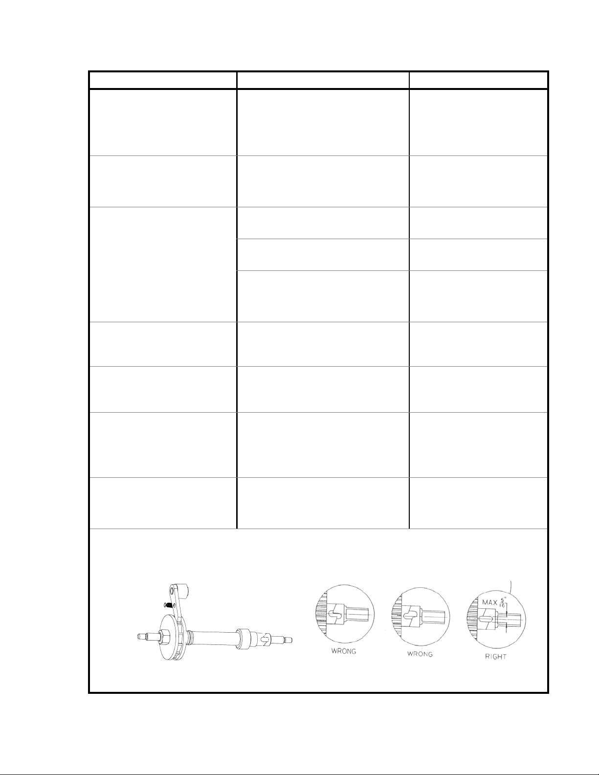
PROBLEM CAUSE SOLUTION
Load is easing down slowly
You have serviced the winch and
now the brake does not work at
all.
The winch is hard to crank down.
Safety Brake will not release
Unit is vertical and brakes will
not release
Units is being serviced or unit is
not in vertical position
The brake on the winch or ratchet dog are
not installed correctly
The brake ratchet or ratchet dog are not
installed correctly
The brake is over-engaged See Illustration and instructions
The brake will not disengage See Illustration and instructions
The idler gear is displaced Make sure that the idler rotates
Unit may not be in the vertical position. Place unit in vertical position and
Mast section or carriage is too close to
mast stop and does not have enough
clearance between mast stops for brakes
to release
Brakes will engage if unit is horizontal or
tilted off center
When load is in position, crank
winch handles forward a half turn
towards the lift to set the brake.
Check the winch drawing in this
manual and correct the
installation problem.
below.
below.
freely and the teeth on the idler
gear are now worn.
wind mast sections up to full
extension.
Use release hook to manually
disengage safety brakes.
Use release hook to disengage
brakes.
If none of these solutions seem
to fix the problem...
NOTE: For proper adjustments on the 2100 Lift winch, the pinion and drive shaft must be in the positions
shown when the lock nut is tightened against the O.D. brake disc to 15 ft. lbs.
*Correct alignment is only visible when load is applied to lift.
Call Distributor’s
Customer Service Department
*
15
Page 16

MAINTENANCE RECORD
Lift Model Number_____________________
Lift Serial Number_____________________
Service Performed:
__________________________________________________________________________
Action Date
__________________________________________________________________________
Action Date
__________________________________________________________________________
Action Date
__________________________________________________________________________
Action Date
__________________________________________________________________________
Action Date
__________________________________________________________________________
Action Date
__________________________________________________________________________
Action Date
__________________________________________________________________________
Action Date
__________________________________________________________________________
Action Date
__________________________________________________________________________
Action Date
__________________________________________________________________________
Action Date
__________________________________________________________________________
Action Date
__________________________________________________________________________
Action Date
16
 Loading...