

Page 1
October 2016
OPERATOR’S MANUAL
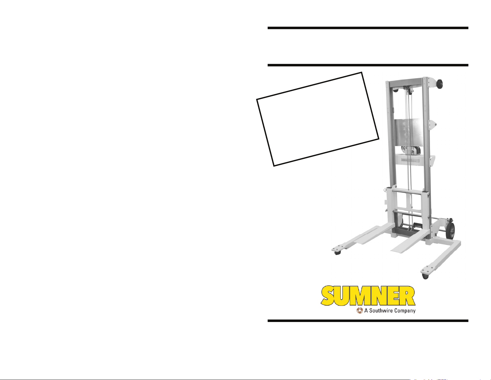
1900 SERIES LIFT
!
B
r
po
f
e
a
e
B
t
e
or
a
d
pe
O
o
c
e
nt
e
you ha
f
i
W
nd
ia
op
m
A
a
r
e
nde
u
o
t
a
r
a
f
e
a
h
l
l
l
a
C
v
t
r
m
za
S
e
’
n
i
s
il
r
a
g t
s
r
Ma
a
i
ds
MN
U
n
t
y
a
r
his
n
nu
w
o
q
G
IN
N
R
f
E
d t
a
t
i
t
R
ue
l
h
h
f
i
his
l.
i
s
,
t
the
s
i
t
.
t
ni
u
.
s
n
o
20
USA
7514 Alabonson Rd.
Houston, TX 77088
p: 281-999-6900
f: 281-999-6966
© Sumner Manufacturing Company, LLC. All rights reserved. * Trademark of Sumner Manufacturing Company, LLC.
CANADA
75 Saltsman Drive,
Unit 5 Cambridge,
Ontario N3H 4R7
p: 519-653-5300
f: 519-653-5305
NETHERLANDS
Midden Engweg
21NL-3882TS
Putten Netherlands
europeansales.com
p: + 31 (0) 85 489 0284
UK
Unit 3 Kempton Road
Keytec 7 Business Park
Pershore, Worcestershire
WR 10 2TA, UK
p: + 44 (0) 1386 556278
f: + 44 (0) 1386 556776
Page 2
Index
Owner’s Responsibilities .............................................................. 2
Operator Safety Instructions ........................................................ 3
Operating Procedure .............................................................. 5-10
Moving Lift to Work Area ....................................................... 5
Moving Lift with Load ............................................................ 5
Lifting and Lowering Loads ................................................... 6
Reversing Forks .................................................................... 6
Using Legs ............................................................................ 7
Carriage Safety Latch............................................................ 8
Storing and Transporting Lift ................................................. 9
Options ....................................................................................... 11
Foot Brake ........................................................................... 11
Work Tray ............................................................................ 11
Dually Wheel Kit .................................................................. 11
Specifications ............................................................................. 12
Lift Diagram ................................................................................ 13
Load Capacity Chart .................................................................. 14
Maintenance Instructions ...................................................... 15-16
Troubleshooting ......................................................................... 17
Maintenance Record .................................................................. 18
OWNER’S RESPONSIBILITIES
Throughout this publication, the words WARNING, CAUTION
and IMPORTANT will be used to alert the user to special
instructions concerning a particular operation that may be
hazardous if performed incorrectly or carelessly.
OBSERVE THEM CAREFULLY !!
WARNING
Hazards or unsafe practices which could result in
severe personal injury or death.
CAUTION
Hazards or unsafe practices which could result in
minor personal injury, product or property
damage.
IMPORTANT
Indicates information or instructions that are
necessary for proper operation and/or
maintenance.
MAINTENANCE RECORD
______________________________________________________________
Action Date
______________________________________________________________
Action Date
______________________________________________________________
Action Date
______________________________________________________________
Action Date
______________________________________________________________
Action Date
______________________________________________________________
Action Date
______________________________________________________________
Action Date
______________________________________________________________
Action Date
______________________________________________________________
Action Date
______________________________________________________________
Action Date
______________________________________________________________
Action Date
______________________________________________________________
Action Date
______________________________________________________________
Action Date
______________________________________________________________
Action Date
______________________________________________________________
Action Date
2
19
Page 3
MAINTENANCE RECORD
Lift Model Number_____________________
Lift Serial Number_____________________
OPERATOR SAFETY INSTRUCTIONS
IMPORTANT
Read and understand Operators Manual before
using Lift.
Service Performed:
______________________________________________________________
Action Date
______________________________________________________________
Action Date
______________________________________________________________
Action Date
______________________________________________________________
Action Date
______________________________________________________________
Action Date
______________________________________________________________
Action Date
______________________________________________________________
Action Date
______________________________________________________________
Action Date
______________________________________________________________
Action Date
______________________________________________________________
Action Date
______________________________________________________________
Action Date
______________________________________________________________
Action Date
______________________________________________________________
Action Date
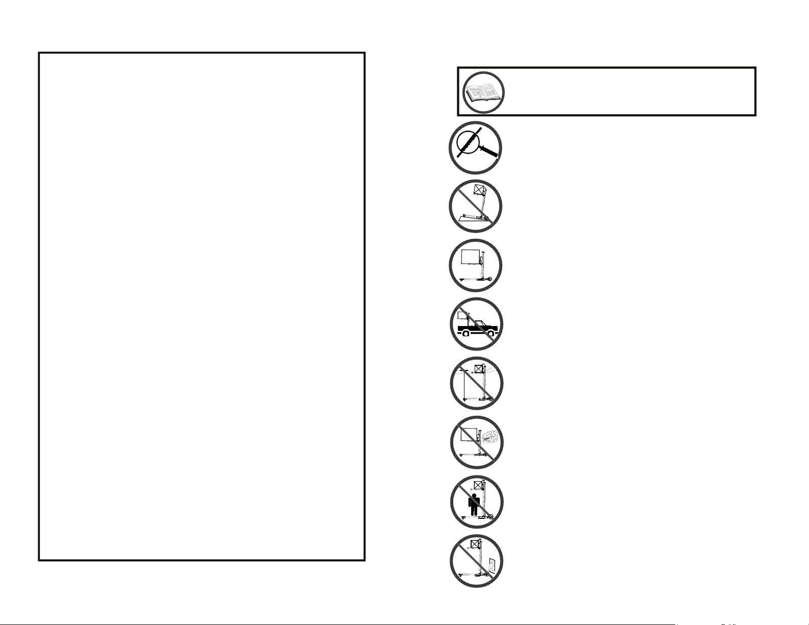
Inspect cable before each use. Do not use if cable
is worn, cut, burnt or otherwise damaged.
Use only on solid level surface. Keep work are
clean and clear of clutter and debris.
Test load balance before lifting. Do not use without
properly installing legs. Never exceed rated load
capacity.
Do not operate from an unstable platform, such as
the bed of a truck.
Stay clear of overhead wires and obstructions.
Never operate in gusty winds. Lifting loads during
high winds can result in the lift tipping over and the
possibility of operator injury.
Do not stand under an elevated load.
Never leave lift unattended with an elevated load.
18
3
Page 4
TROUBLESHOOTING
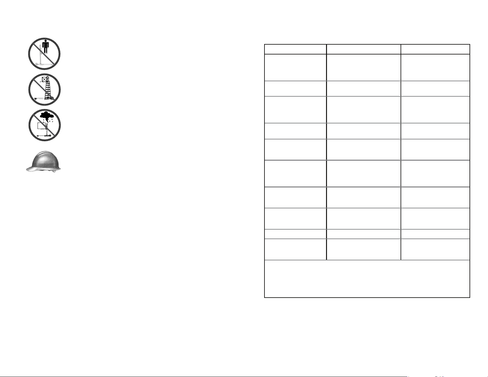
Do not use to lift personnel. Do not sit or stand on
forks.
Do not climb on mast or put a side load on mast.
Do not use unit to support ladders for climbing or
hoisting.
Do not use unit outside in thunder, lightning, or
severe weather.
Wear proper clothing. Hard hat, safety shoes and
gloves should be worn as a precaution when
operating this lift.
Avoid horseplay around equipment, and keep bystanders at a
safe distance. Do not allow children to operate this unit and
always keep them out of work areas.
Do not misuse the lift. Perform only the functions for which the
lift was designed.
Never use two lifts in tandem to lift a load that exceeds the
capacity of a single lift.
Prior to each use of the unit, inspect all moving parts and the
lifting strap to ensure they are in proper working condition.
PROBLEM CAUSE SOLUTION
Masts not rising in
succession
Load is easing down
slowly
You have checked the
winch and the brake
does not work at all.
The winch is hard to
crank down.
If none of these
solutions seem to fix the
problem...
NOTE: Mast sections may rise out of succession when load is near maximum
capacity. If this occurs, the masts will correct themselves during continued use or
when the load is removed from the forks. Movement of the mast sections will not
affect the position of the forks. The carriage must elevate to the top of the top mast
section before any mast sections begin to rise, and it should lower last.
load does not exceed the maxi-
Slideways obstructed. Inspect
tracks for debris, grease, or any
Slideways are clean but masts
dog are not installed correctly or
Overloading
Check to make sure that the
mum allowable load limit.
Load may not be centered
properly on the forks.
foreign obstruction.
Inspect Load Cable for
damage.
still not sliding freely.
The brake on the winch or
ratchet dog are not installed
correctly.
The brake ratchet or ratchet
are damaged and/or worn.
The brake is over-engaged Remove the load and turn
The brake will not disengage Replace the winch.
Remove excess weight.
Check load capacity and
reposition load.
Clean mast sections with a
degreaser or brake cleaner
and lubricate with a silicon
lubricant.
If cable is cut, worn, frayed or
kinked replace the cable.
Inspect mast sections for
damage. Replace damaged
mast section.
When load is in position,
crank winch handles clock-
wise a half turn to set the
brake.
Replace the winch.
the winch handle counter
clockwise.
Call distributor’s
Customer Service
Department.
4
17
Page 5

11. Replace the winch cover.
General Maintenance:
1. Check the winch handle for wear or bends.
2. Examine all bolts and nuts to be sure they are tight.
3. Legs, forks, braces and base should be dent free and damage free.
4. Check for damage (indentations) which can restrict the rotation of the
Load Cable.
5. Make sure Load Cable is seated flat and has no twists or kinks restricting
rotation.
7. Check legs by sliding them into each position to check locking mechanism.
8. Inspect masts and carriage hold-down device.
9. Raise mast sections to inspect for free, smooth sliding action. Make sure
slideways are free of dust and oxidation and spray a light coat of silicone
lubrication in slideways.
10. Make sure caster wheels and 8” transport wheels rotate freely and are
undamaged.
11. Check to be sure that all mast covers are attached to the lift.
OPERATING PROCEDURE
1. Moving Lift to Work Area (No Load)
The lift is normally moved to the job site by tilting back and rolling
on its 6” tires. Note: Do not pull by the lifting cable.
2. Moving Lift in Work Area (With Load)
Although it is best to move the unit to the job site unloaded, light
loads may be transported as long as the unit is rolled on the
casters and transport wheels on a level surface. Always have
the load in the lowest possible position before moving the unit.
CAUTION
If a load is being transported, it should be secured
to the forks to avoid shifting.
WARNING
Moving the unit with elevated loads should be
contained to short distances; i.e., 10-15 feet/4-5
meters.
WARNING
Replace all worn or damaged parts only with
Sumner parts.
WARNING
Modifying the lift in any way can cause injury or
death!
16
If it is necessary to move the unit with an elevated load:
Make sure the area is clear of obstructions
Keep personnel away from the load and behind the
operator’s position
Move the unit slowly, avoiding sudden jerky starts and stops
Make sure the load is secure and properly balanced. Note
load capacity at given centers on page 14.
5
Page 6
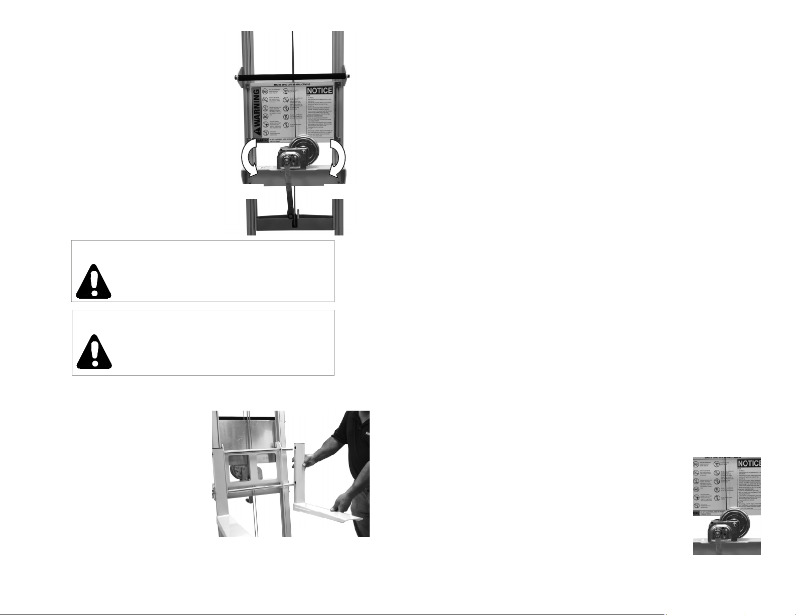
3. Lifting and Lowering Loads
Use the winch to crank forks up or
down into the desired position.
Any unstable load must be
balanced and secured to the forks
prior to lifting.
Turn winch crank clockwise to
elevate the load, while watching for
overhead obstructions. Turn winch
handle counter clockwise to lower
the load.
CAUTION
Make sure the floor surface is level.
WARNING
No riders allowed on this unit. This is
not a personnel lift and never should be
used for hoisting or moving people.
4. Removing and Reversing Forks
The forks on the 1900 series lift
are removable. Removing the
forks is recommended for storage
and is required for reversing. The
forks may be reversed to allow for
an increased lifting height.
6
MAINTENANCE INSTRUCTIONS
Before each use:
1. Inspect the lifting cable for frays, cuts or burns. If any damage is visible
on the lifting strap, do not use the lift.
2. Make certain winch operates freely and lifting cable is not tangled on the
winch drum.
3. Check forks, legs, and base for bends.
4. Make sure caster wheels move freely.
Recommended Inspection Every 6 Months:
1. Inspect the lifting cable for frays, cuts or burns. If any damage is visible
Raise Lower
on the lifting cable, do not use the lift.
2. Make certain winch works freely and that there are no loose or damaged
parts.
Winch Maintenance:
1. Be sure that the winch cover is on the winch.
2. Check ratchet dog and brake ratchet for wear. If any wear is visible,
replace the winch. If not, lubricate both parts with a light oil.
3. Inspect gear teeth for wear. If there is no sign of visible wear, brush
teeth with 50-wt. Motor oil.
4. For proper brake adjustment see “Troubleshooting” section on page 17.
Replacing the Lifting Strap:
1. Lower the carriage to engage the safety latch.
2. Remove the large gear cover from the winch.
3. Remove the cable anchor bolt from the top of the front mast.
4. Remove the clamp attaching the cable to the side of the winch drum.
5. Pull the old cable through the lift out the front. Make note of the direction
of the reeve.
6. Attach the new cable to the top of the front mast using the anchor bolt.
8. Re-reeve the new cable through the lift using notes taken
in step 5.
9. Attach new cable to winch drum using clamp that was
removed in step 4. Note: The cable must be fed from
the top of the winch under the left side of the drum
(looking from the back of the lift). Winding the cable
under the right side of the drum will prevent the
brake from working.
10. Wind the slack cable tightly and evenly across the load
drum.
15
Page 7
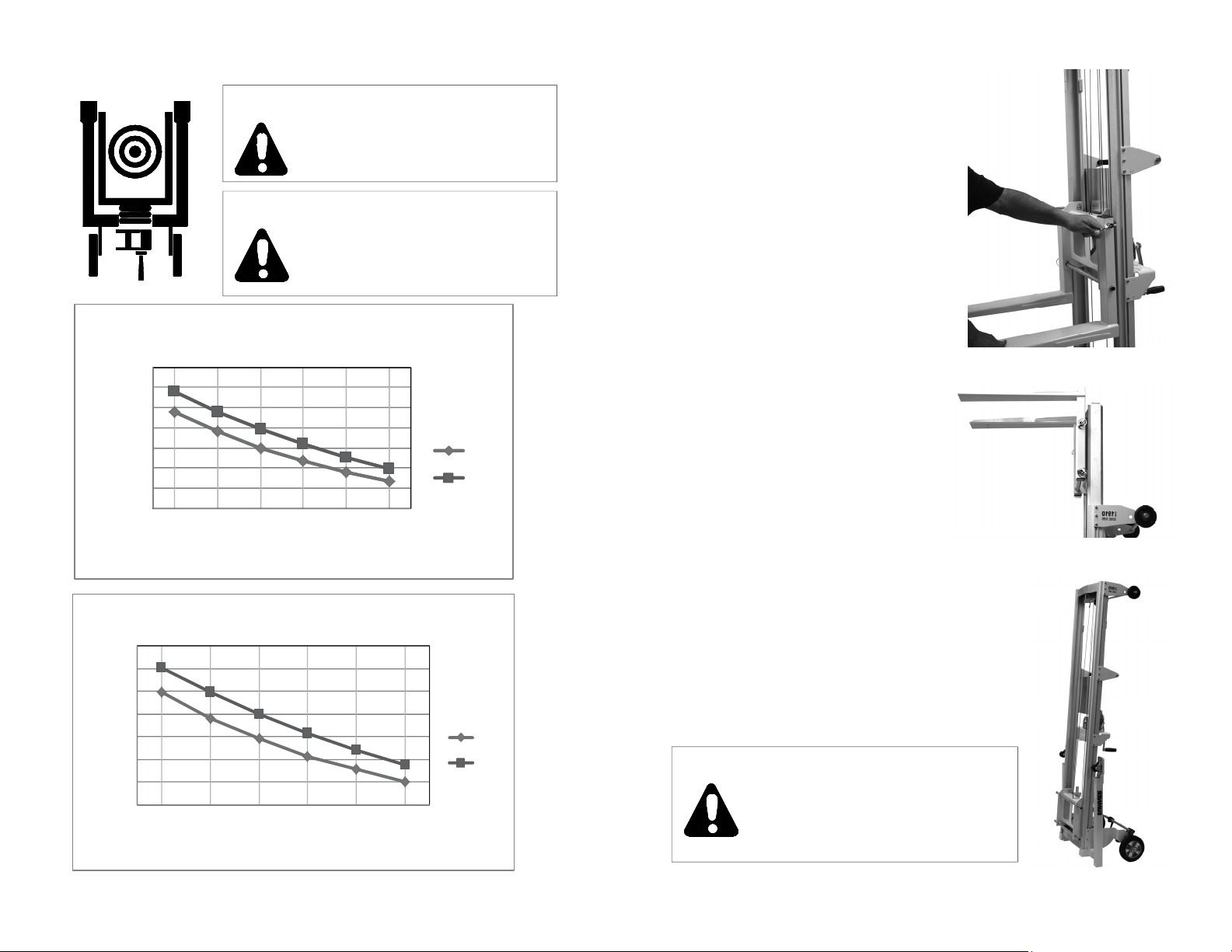
LOAD CAPACITY CHART
WARNING
The center of gravity of the load
should never extend past 20”
from the carriage.
WARNING
The center of gravity of the load
should always be centered
between the fork arms and as far
back towards the lift as possible.
1900 SeriesLoadCapacity(Imperial)
460
410
360
310
260
Load (lb)
210
160
110
10 12 14 16 18 20
Distannce fromFace ofForks (in)
1900SeriesLoadCapacity(Metric)
200
180
160
140
120
Load(kg)
100
80
60
25.430.535.640.645.750.8
Distance fromFace ofForks (cm)
1910
1908
1910
1908
To remove the forks, remove the two
spring pins. Slide the fork outward off
of the mounting bars. Repeat for the
other fork arm.
Reverse this procedure to install the
forks.
To invert the forks, remove the fork
arms as described above. Rotate
the fork 180 degrees and reinstall.
5. Using the Legs
The 1900 Series Lift will arrive with the legs
in the upright storage position. Before
attempting to attach the forks and use the lift,
the legs must be rotated to the operating
position.
CAUTION
Attempting to install the forks
and/or use the lift with the legs
in the storage position will
result in the lift being unstable.
14
7
Page 8
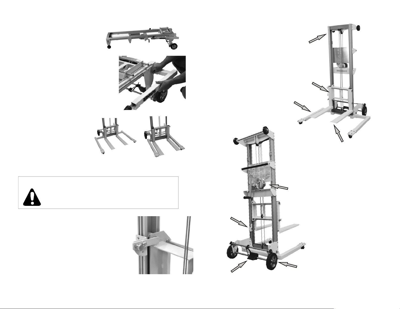
To reposition the legs, lay the
lift down on a flat level surface.
Using one hand, pull the spring loaded
pin while sliding the leg out of the base
with the other hand. Rotate the leg 90°
and reinsert it into the base with one
hand while pulling the spring loaded
plunger with the other hand. Repeat
this procedure for the other leg.
The legs can be positioned
in two configurations,
narrow and wide. The
narrow configuration allows
access into confined
spaces. While not required,
the wide configuration allows for greater stability
on lifts greater than 6 ft.
LIFT DIAGRAM
Mast
Carriage Assembly
Base Leg
Lifting Forks
WARNING
Lifting a load without the spring loaded pins fully
engaged in the leg locating holes can cause the
lift to become unstable and/or tip over.
6. Carriage Safety Latch
The 1900 Series comes equipped with a
safety latch to engage the carriage. The
purpose of the latch is to prevent the mast
sections from extending during
transportation. To use your lift, disengage
the Safety Latch from the carriage and
install the legs and forks into their operating
positions.
8
Winch
Assembly
Carriage Safety Latch
8” Transport Wheels
Foot Brake
13
Page 9
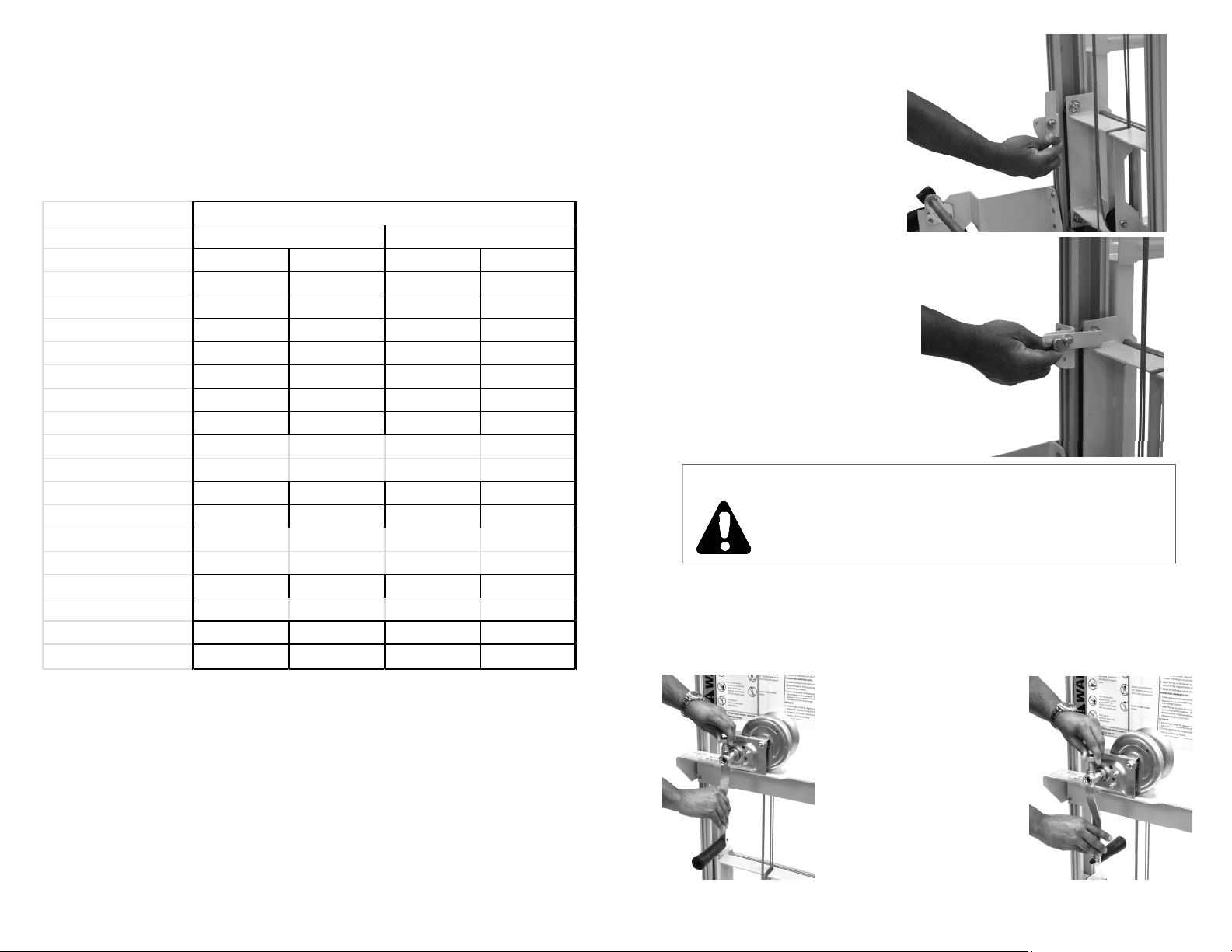
SPECIFICATIONS
Specifications
1908 1910
Dimensions Imperial Metric Imperial Metric
HeightStowed 5'81/4" 1.73m6'7.5" 2.02m
ForksDown 8'2" 2.49m9'91/2" 2.98m
WidthMax 3'63/4" 1.08m3'63/4" 1.08m
WidthMin 2'41/2" 0.72m2'41/2" 0.72m
InsideMax 3'3/4" 0.93m3'3/4" 0.93m
LengthStowed 1'41/2" 0.42m1'41/2" 0.42m
LengthOperating 3'10" 1.16m3'10" 1.16m
The Carriage Safety Latch is
engaged at the top of the
carriage. Lower the carriage
all the way down to it’s lowest position.
Pull out on the spring loaded
plunger pin.
While holding the plunger pin
out, rotate the latch 90 degrees
and release the plunger. Make
sure the spring loaded plunger
pin engages into the hole
locking the latch in the
horizontal position.
Reverse this procedure to release the Safety Latch.
ForkSpecifications
Width 4" 10.2cm 4" 10.2cm
Fork
ForkLength 221/4"56.5cm 221/4"56.5cm
Weight
NetWeight 168lb 76kg 172lb 78kg
LoadCapacity 400lb 180kg 350lb 160kg
LoadCenter 10" 25.4cm 10" 25.4cm
12
WARNING
Failing to remove the Carriage Latch before attempting to raise a load can result in damage to
the lift.
7. Storing and Transporting the Lift
To store and/or transport the lift, remove the forks (described in
section 4), place the legs in the storage position (described in
section 5 and reverse the winch handle.
To reverse the winch
handle, pull the spring
loaded pin with one hand
while sliding the handle
off with the other hand.
Rotate the handle 180°
and reinstall. This places
the winch handle in a
secure location for
transportation or storage.
9
Page 10
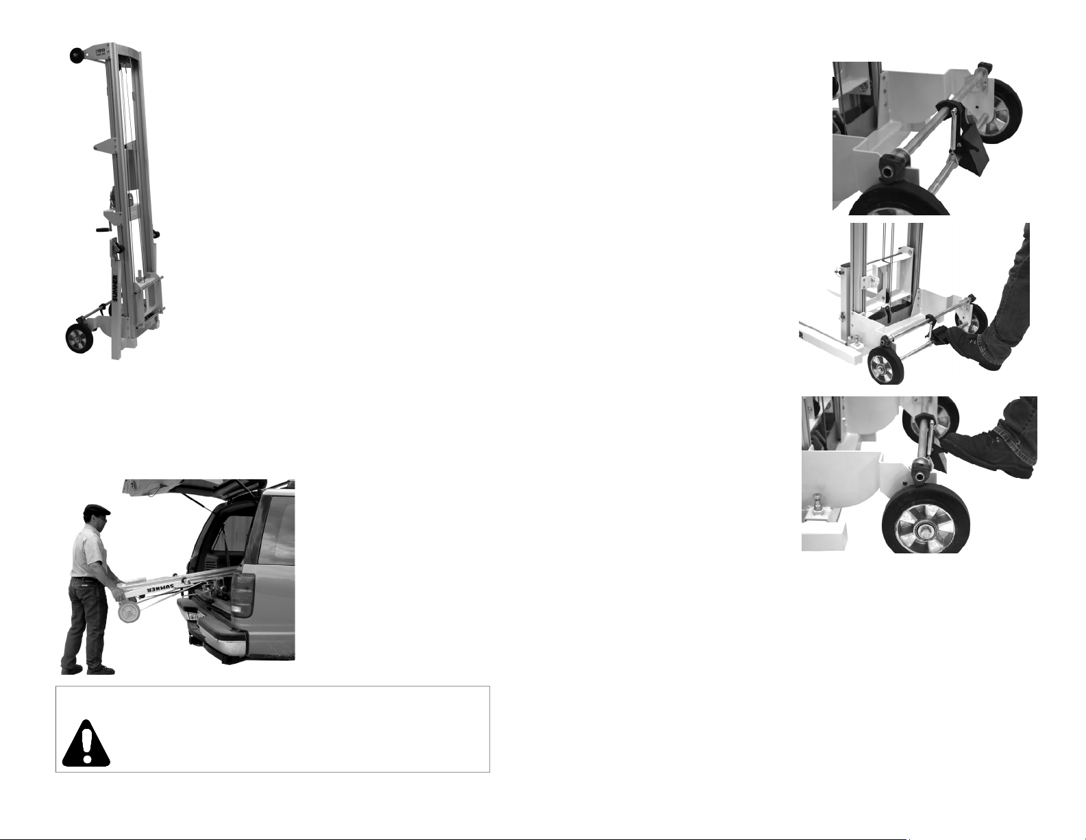
With the legs and winch handle in the storage
positions, the lift is compact and can be
stowed easily in the upright position.
To load the lift into a truck or van, lean the lift back onto the
winch side until the 4” wheels contact the truck bed. Raise the
bottom end of the lift, and roll the unit into position.
CAUTION
Make sure the Mast Safety Latch is securely
attached to the carriage before transporting the lift.
Foot Brake
The 1900 Series Lift is outfitted
with a foot brake. When engaged, the brake will prevent the
8” transport wheels from rotating.
To operate the brake, press
the brake pad with your foot
until the brake locks into
place. When you hear the
“snap” you know the brake is
locked into place.
To release the brake, press
the release tap with your foot
until the brake unlocks.
When you hear the “snap”
you will know the brake is
unlocked.
10
11
 Loading...